Embed Size (px)
Citation preview

ARTICLE
Received 19 Aug 2015 | Accepted 19 Oct 2015 | Published 11 Dec 2015
A universal self-charging system driven by randombiomechanical energy for sustainable operationof mobile electronicsSimiao Niu1,*, Xiaofeng Wang1,2,*, Fang Yi1, Yu Sheng Zhou1 & Zhong Lin Wang1,3
Human biomechanical energy is characterized by fluctuating amplitudes and variable low
frequency, and an effective utilization of such energy cannot be achieved by classical energy-
harvesting technologies. Here we report a high-efficient self-charging power system for
sustainable operation of mobile electronics exploiting exclusively human biomechanical
energy, which consists of a high-output triboelectric nanogenerator, a power management
circuit to convert the random a.c. energy to d.c. electricity at 60% efficiency, and an energy
storage device. With palm tapping as the only energy source, this power unit provides a
continuous d.c. electricity of 1.044 mW (7.34 W m� 3) in a regulated and managed manner.
This self-charging unit can be universally applied as a standard ‘infinite-lifetime’ power source
for continuously driving numerous conventional electronics, such as thermometers,
electrocardiograph system, pedometers, wearable watches, scientific calculators and wireless
radio-frequency communication system, which indicates the immediate and broad
applications in personal sensor systems and internet of things.
DOI: 10.1038/ncomms9975 OPEN
1 School of Materials Science and Engineering, Georgia Institute of Technology, Atlanta, Georgia 30332, USA. 2 Department of Precision Instrument, TsinghuaUniversity, Beijing 100084, China. 3 Beijing Institute of Nanoenergy and Nanosystems, Chinese Academy of Sciences, Beijing 100083, China. * These authorscontributed equally to this work. Correspondence and requests for materials should be addressed to Z.L.W. (email: [email protected]).
NATURE COMMUNICATIONS | 6:8975 | DOI: 10.1038/ncomms9975 | www.nature.com/naturecommunications 1

Arapid development in personal electronics and sensor
networks1,2 has raised urgent and challengingrequirements for their portable and sustainable power
sources, which are now mostly using batteries. In many modernmobile electronics and internet of things, batteries have becomethe largest and heaviest component of the entire unit, and theyare required to be charged periodically due to limited lifetime,leading to an inevitable design trade-off dilemma betweenmobility (size and weight) and sustainability (lifetime).Although this dilemma can be eased to some extent with thedevelopment of high-energy-density materials3–5, it is not solvedfrom the root. A fundamental solution to this challenge is todevelop technologies that can constantly convert ambient energyinto electricity and get the battery continuously charged to ensureits sustainable and maintenance-free operation6–8. Ambientenergy sources exist in various forms, such as mechanical,thermal9,10, chemical11 and solar12,13. Distinguished from others,mechanical energy is the one that is available almost everywhereand at any time, to name a few, gentle airflow, ambient sound,vibration, human body motion, ocean waves and so on. Althoughthis type of energy could be converted by using traditionalgenerators based on electromagnetic induction, they are usuallyheavy in weight and large in size. More importantly, their designsare rigid and cannot be easily adapted for harvesting body motionenergy and vibration energy due to their intrinsic structurecomplexity14–17. Finally, as limited by the working mechanism,an electromagnetic generator usually produces a small outputvoltage (o1 V) when its size is small, so that the output powercannot be effectively utilized because of the threshold voltagerequired to overcome a diode to function in rectification.Alternatively, micro-electromechanical-based energy harvestingusing electrostatic or piezoelectric effect commonly provides apower level of BmW (refs 18–23), so it can hardly meet the needsfor wearable and portable electronics that require mW–W level ofpower.
Contact electrification, known for thousands of years, is aboutcharge transfer between two materials when they contact witheach other, but this effect is rarely utilized for energy harvestinguntil recently24,25. Triboelectric nanogenerators (TENGs) wereinvented by incorporating contact electrification and electrostaticinduction, and it has been demonstrated as a promisingtechnology with numerous advantages, including large powerdensity, high efficiency, diverse choice of materials for fabrication,low cost and lightweight26–29. TENG has various working modesthat cover almost all of the mechanical motions in our daily life.Besides, it can be made into thin-film structure with highcompactness and three-dimensional integration scalability thatcan potentially lead to mW–W output power. However, to embedTENGs into electronic system for practical applications, there aremajor challenges to overcome. First, due to the randomness ofmechanical energy source and the intrinsic capacitive behaviourof TENGs, the output of a TENG normally is in the form ofpulsed a.c. signal with variable frequency30. Second, TENGusually has a high output voltage in the order of hundreds of voltsbut low current in the order of microamps, which has a hugemismatch with the requirement of mobile electronics. Besides, thehigh inherent impedance of TENGs results in ultralow energyconversion efficiency using conventional transformer for powermanagement. Third, owing to the a.c. output, TENGs cannot betaken as steady power sources for directly driving electronics.Therefore, an energy storage unit is necessary to serve as a‘reservoir’ for collecting the generated charges and outputtingthem in a managed and regulated manner. However, a directintegration of a TENG with an energy storage device has shownextremely low charging efficiency and large power loss due to thehuge impedance mismatch between TENGs and energy storage
units, where TENGs have inherently high impedance whileenergy storage devices such as batteries and capacitors usuallyhave low impedance31,32. Therefore, although there are severalTENG-based ‘self-powered’ systems being reported, all of thesesystems either cannot work continuously due to the low level ofgenerated d.c. power or the entire system cannot be exclusivelydriven by the harvested energy if the data measurement andprocessing systems as well as data transmission components areincluded.
Here we present a genuine self-powered system to meet mWrequirement of personal electronics by solving the challengespresented above. The system includes a TENG, a powermanagement circuit and a low-leakage energy storage device.We perform system-level optimization to ensure the collaborativework of all the system components. Especially, a power manage-ment circuit is designed to solve the impedance mismatchproblem, which can achieve 90% board efficiency and 60% totalefficiency, about two orders of magnitude improvement com-pared with direct charging. Driven by palm tapping, this powerunit can provide a continuous d.c. electricity of 1.044 mW onaverage power in a regulated and managed manner that can beuniversally applied as a standard power source for continuouslydriving numerous conventional electronics, such as a thermo-meter, a heart rate monitor (electrocardiograph (ECG) system),a pedometer, a wearable electronic watch, a scientific calculatorand a wireless radio-frequency communication system. Our studydemonstrates the first power unit that utilizes widely accessiblebiomechanical energy source to sustainably drive a broad range ofcommercial mobile and wearable electronic devices.
ResultsDesign of the system framework. This integrated human-motion-driven self-powered system is shown in Fig. 1, including ahuman-motion-powered self-charging power unit and functionalcircuits for different applications. The TENG scavenges thehuman biomechanical energy and converts it to a.c. electricity.Then this a.c. electricity is converted to a d.c. electric output thatmatches to the input of the energy storage unit by the powermanagement circuit. Finally, the energy storage unit provides d.c.electricity to the whole functional circuits, including sensors, dataprocessors, displays and wireless transmitters. The signals fromsensors and data processors are either visualized on a LCD dis-player or sent out remotely through a wireless transmitter.
Design of the multilayered TENG. The TENG is first designedand optimized to efficiently harvest human biomechanical energy.We choose a multilayered attached-electrode contact-modeTENG to effectively collect the energy from human walking andrunning. The basic working principle of attached-electrodecontact-mode TENGs is shown in Fig. 1b, which utilizes theconjugation between contact electrification and electrostaticinduction33. As shown in Fig. 1c, a Kapton film is shaped into azigzag structure with 10–15 layers34. For each layer, a thinaluminium foil and fluorinated ethylene propylene (FEP) layerare utilized as the triboelectric materials. The Al foil also serves asone electrode. Copper is evaporated at the backside of the FEPlayer as the other electrode. As shown in Fig. 1d, the as-fabricatedTENG has small volume and lightweight (5.7� 5.2�1.6 cm/29.9 g for a 10-layer TENG and 5.7� 5.2� 2.4 cm/43.6 gfor a 15-layer TENG). The optimum thickness of FEP forthis design is 125 mm according to theoretical calculation andstructural design considerations (Supplementary Fig. 1). Besides,nanostructures are created on the surface of FEP and Al foil toenhance the device performance (Supplementary Fig. 2)35.Embedded in the shoe insoles, a human walking can drive this
ARTICLE NATURE COMMUNICATIONS | DOI: 10.1038/ncomms9975
2 NATURE COMMUNICATIONS | 6:8975 | DOI: 10.1038/ncomms9975 | www.nature.com/naturecommunications
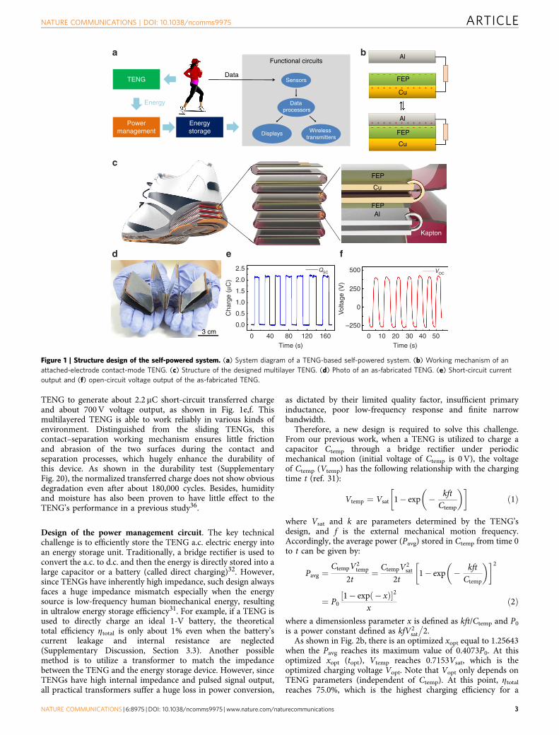
TENG to generate about 2.2 mC short-circuit transferred chargeand about 700 V voltage output, as shown in Fig. 1e,f. Thismultilayered TENG is able to work reliably in various kinds ofenvironment. Distinguished from the sliding TENGs, thiscontact–separation working mechanism ensures little frictionand abrasion of the two surfaces during the contact andseparation processes, which hugely enhance the durability ofthis device. As shown in the durability test (SupplementaryFig. 20), the normalized transferred charge does not show obviousdegradation even after about 180,000 cycles. Besides, humidityand moisture has also been proven to have little effect to theTENG’s performance in a previous study36.
Design of the power management circuit. The key technicalchallenge is to efficiently store the TENG a.c. electric energy intoan energy storage unit. Traditionally, a bridge rectifier is used toconvert the a.c. to d.c. and then the energy is directly stored into alarge capacitor or a battery (called direct charging)32. However,since TENGs have inherently high impedance, such design alwaysfaces a huge impedance mismatch especially when the energysource is low-frequency human biomechanical energy, resultingin ultralow energy storage efficiency31. For example, if a TENG isused to directly charge an ideal 1-V battery, the theoreticaltotal efficiency Ztotal is only about 1% even when the battery’scurrent leakage and internal resistance are neglected(Supplementary Discussion, Section 3.3). Another possiblemethod is to utilize a transformer to match the impedancebetween the TENG and the energy storage device. However, sinceTENGs have high internal impedance and pulsed signal output,all practical transformers suffer a huge loss in power conversion,
as dictated by their limited quality factor, insufficient primaryinductance, poor low-frequency response and finite narrowbandwidth.
Therefore, a new design is required to solve this challenge.From our previous work, when a TENG is utilized to charge acapacitor Ctemp through a bridge rectifier under periodicmechanical motion (initial voltage of Ctemp is 0 V), the voltageof Ctemp (Vtemp) has the following relationship with the chargingtime t (ref. 31):
Vtemp ¼ Vsat 1� exp � kftCtemp
� �� �ð1Þ
where Vsat and k are parameters determined by the TENG’sdesign, and f is the external mechanical motion frequency.Accordingly, the average power (Pavg) stored in Ctemp from time 0to t can be given by:
Pavg ¼CtempV2
temp
2t¼ CtempV2
sat
2t1� exp � kft
Ctemp
� �� �2
¼ P01� exp � xð Þ½ �2
xð2Þ
where a dimensionless parameter x is defined as kft/Ctemp and P0
is a power constant defined as kfV2sat
�2.
As shown in Fig. 2b, there is an optimized xopt equal to 1.25643when the Pavg reaches its maximum value of 0.4073P0. At thisoptimized xopt (topt), Vtemp reaches 0.7153Vsat, which is theoptimized charging voltage Vopt. Note that Vopt only depends onTENG parameters (independent of Ctemp). At this point, Ztotal
reaches 75.0%, which is the highest charging efficiency for a
TENG
Powermanagement
Energystorage
Energy
Data
Functional circuitsAl
Cu
Al
FEP
FEP
Cu
Sensors
Data processors
Displays Wireless transmitters
3 cm
FEP
Al FEP
Cu
Kapton
+ + + + + + + + + + +
+ + + + + + + + + + +
2.5
2.0
1.5
1.0
0.5
0.0
0 40 80 120 160Time (s) Time (s)
0 10 20 30 40 50
500
250
–250
0
Cha
rge
(μC
)
Vol
tage
(V
)
QSC VOC
– – – – – – – – – – –
– – – – – – – – – – –
ba
c
d e f
Figure 1 | Structure design of the self-powered system. (a) System diagram of a TENG-based self-powered system. (b) Working mechanism of an
attached-electrode contact-mode TENG. (c) Structure of the designed multilayer TENG. (d) Photo of an as-fabricated TENG. (e) Short-circuit current
output and (f) open-circuit voltage output of the as-fabricated TENG.
NATURE COMMUNICATIONS | DOI: 10.1038/ncomms9975 ARTICLE
NATURE COMMUNICATIONS | 6:8975 | DOI: 10.1038/ncomms9975 | www.nature.com/naturecommunications 3

capacitor charged from 0 V by TENG (SupplementaryDiscussion, Section 3.4).
With the above theoretical understanding of TENG chargingcharacteristics, we can design the following charging strategy formaximized energy storage efficiency. First, a small temporarycapacitor (Ctemp) is charged by the TENG from 0 V. Once itsvoltage reaches Vopt (impedance match condition is reached), theenergy stored in Ctemp begins to be transferred to the final energystorage unit (a large capacitor or a battery) to maximize Ztotal.When the energy transfer finishes, the voltage of Ctemp dropsback to close to 0, and then Ctemp is recharged by the TENG toreach Vopt again. With this optimized charging cycle, Ztotal cantheoretically reach 75% (Supplementary Discussion, Section 3.4).
This theoretical charging cycle can be realized by a two-stagepower management circuit, as shown in Fig. 2a. At the first stage,a temporary capacitor Ctemp is charged by a TENG through abridge rectifier. The second stage is for energy transfer from Ctemp
to the final energy storage unit. Since transferring electrostaticenergy directly from a small capacitor to a large capacitor (or abattery) results in huge energy loss (Supplementary Discussion,Section 4), two automatic electronic switches (controlled by alogic control unit, the power of both switches and their logiccontrol unit is supplied from the final energy storage unit) and acoupled inductor are utilized in the second stage37,38. Thedetailed operation process is shown below to achieve efficientenergy transfer in this stage. First, both the switches J1 and J2 areopen to avoid interference of the charging process of Ctemp. WhenVtemp reaches Vopt, electronic switch J1 closes. As a result, the
energy starts to transfer from Ctemp to inductor L1 and Vtemp
starts to drop. When the energy is thoroughly transferred to L1,the switch J1 opens and J2 closes. As a consequence, the current ofL1 falls to 0 instantaneously. Besides, since the total magnetic fluxlinkage in the coupled inductance cannot change abruptly, thecurrent of L2 will suddenly rise up, corresponding to the energytransfer from L1 to L2. Finally, the energy stored in L2 willautomatically transfer to the final energy storage unit because ofthe closure of J2. When the energy stored in L2 is thoroughly sentout, J2 is open again and another charging cycle begins.
Performance of the power management circuit. The operationof such a power management system is shown in Fig. 2c–g.Figure 2c shows the voltage profiles of both temporary capacitor(Vtemp) and final storage capacitor (Vstore) when one 15-layerTENG and a 1-mF Al-electrolyte capacitor were utilized as theenergy harvester and the energy storage unit (Cstore), respectively(Supplementary Fig. 9). While the TENG is driven by palmtapping, Ctemp is charged by the TENG and discharged throughthe energy transfer network, resulting in an oscillation of Vtemp
between 230 and 0 V. During the drop phase of Vtemp, Vstore israised up by the transferred energy from Ctemp. Note that if therewas no mechanical energy input (from 5.4 to 5.7 s in Fig. 2c), bothVtemp and Vstore will decrease slowly because of the system leakagecurrent and the power consumption of the electronic switches.The performance of the energy transfer network can be evaluatedby the board efficiency (Zboard), which is defined as the ratio of the
TENG
D1
D4
D3
D3L1
J2
L2
J1
Ctemp
VtempVstore
+
–
–
+
Energystorage
Functionalcircuits
0.4
0.35 6.05
6.04
6.03
6.02
0 5 10 15
0.30
0.25
0.20
0.15
0.10
0.051 10
6.4
3.703.653.603.553.503.453.403.353.30
0 50 100 150Time (s)
200 250 300
1.044 mW d.c. power at 39 kΩ load
0.202 mW d.c. power at 180 kΩ load
20 kΩ30 kΩ39 kΩ60 kΩ70 kΩ
Direct measuredDirect fittingBoard measuredBoard fitting
0 2 4 6 8Time (s)
6.0
5.6
5.2
0.3
0.2
0.1
0.0
0 02 24 46 68 810 10 12 14x
Pav
g/P
0
Vst
ore
(V)
6.8
6.4
6.0
5.6
5.2
Vst
ore
(V)V
temp (V
)V
stor
e (V
)
Time (s)
Time (s)
250
200
150
100
50
0
MeasurementInterpolationA
vera
ge p
ower
(m
W)
Sto
red
volta
ge (
V)
Resistive load (MΩ)
RL = 180 kΩ
a
b
e f g
c d
Figure 2 | Design of the power management part for regulated TENG outputs. (a) Circuit diagram of the power management circuit. (b) Theoretical
calculation of the optimized charging time to demonstrate the design of the power management circuit. (c) Board efficiency measurement results.
(d) Measurement of the maximum d.c. power of this system driven by human biomechanical energy. (e,f) Total efficiency measurement results.
(e) Measurement of the a.c.-harvested power from a resistor. (f) Measurement of the d.c.-harvested power from the power management circuit.
(g) Comparison of the charging current between direct charging and board charging.
ARTICLE NATURE COMMUNICATIONS | DOI: 10.1038/ncomms9975
4 NATURE COMMUNICATIONS | 6:8975 | DOI: 10.1038/ncomms9975 | www.nature.com/naturecommunications

total energy stored in Cstore to the total energy transferred outfrom Ctemp. From the data shown in Fig. 2c, the total energy sentout from Ctemp is calculated as 9.160 mJ, while the total energystored in Cstore is calculated as 8.243 mJ (SupplementaryDiscussion, Section 5). So this energy transfer network hasZboard¼ 90.0%, which is hugely improved in comparison withthat of one-step direct energy transfer process (SupplementaryDiscussion, Section 4).
To measure the d.c. power delivered to the load by the systemas driven by palm tapping, a load resistor RL is connected inparallel with the storage capacitor (see Supplementary DiscussionSection 3.2 for detailed experimental configuration). The storagecapacitor Cstore is charged by two 15-layer as-fabricated TENGsand then provides d.c. power for RL. As shown in Fig. 2d, whenRL is high, the power consumption of RL is lower than the powerprovided by TENG, so Vstore has a positive slope with time.As the load resistance RL decreases, the load power consumptionincreases and the charging slope of Vstore decreases. When thecharging slope reduces to 0 (39 kO, Supplementary Fig. 5), thepower delivered from palm tapping is the same as the powerconsumed on the load, which is calculated as 1.044 mW(7.34 W m� 3). When RL continues to decrease (20 kO), thepower delivered from palm tapping is not enough to compensatethe energy consumption on the load, and the charging slopebecomes negative.
The most important parameter of the power managementcircuit is the total efficiency Ztotal, which is defined as the ratio ofthe maximum d.c. power stored into the storage unit to themaximum a.c. power delivered to a resistive load (SupplementaryDiscussion, Section 3). To measure Ztotal, first the maximum a.c.power delivered to a resistive load can be extracted by the TENGresistance-matching measurement (Supplementary Fig. 8). Asshown in Fig. 2e, the maximum a.c. energy generated by TENGis 0.3384 mW at an optimum load resistance of 4.26 MO.Second, the maximum d.c. power delivered through the powermanagement board can be measured using the method shownabove, which is 0.2023 mW (Fig. 2f) under the same mechanicaltriggering (from an electric motor). Therefore, Ztotal is calculatedas 59.8%.
Compared with direct charging, the power management boardshows a huge enhancement of the charging efficiency. In anothersupercapacitor charging experiment (see SupplementaryDiscussion Section 6 for detailed experimental configuration),the net supercapacitor charging current is 13.82 nA throughdirect charging and 15.14 mA through the designed powermanagement board, which is improved by as high as 1,096times! Note that a transformer shows even worse performancethan direct charging. As shown in Supplementary Fig. 11, thecharging current of a supercapacitor cannot even compensatethe leakage current when a 10:1 transformer is utilized as theimpedance match network.
Broad applications as a sustainable d.c. power source. Thishuman-motion-charged power unit have wide applications inrealizing self-powered human-activity sensors, which makes themself-sufficient without any external power sources. Several appli-cations have been demonstrated by utilizing this self-charged unitto sustainably drive various commercial electronic systems(Fig. 3a). In the first demo, this human-motion-charged powerunit was connected to a commercial temperature sensor (Fig. 3b,detailed system diagram is shown in Supplementary Fig. 12). Thistemperature sensor utilizes a thermal couple to sense the externalenvironment temperature. Then the sensing analogue signal isdigitalized through an analogue–digital converter (ADC). Finally,the digital signal is shown on a LCD display to fulfil the
visualization of the output. As shown in Supplementary Movie 1,even under very gentle 1.6 Hz palm tapping (palm tapping isutilized mainly for easier filming purpose, other kinds ofhuman motion such as foot tapping is also suitable for theapplication), this human-motion-charged power unit couldsupply enough power to maintain continuous operation ofthe temperature sensor. There were not any external powersources/batteries inside to power any part of the wholefunctionalized system.
This kind of power unit can also serve as power source forhuman health monitoring. As a typical example, we realized aself-powered ECG system (Fig. 3c, detailed system diagramshown in Supplementary Fig. 13). The bioelectricity signal acrosshuman left hand and right hand was first collected through theECG signal collector (two conducting Al rods), and thenamplified and filtered through an ECG signal amplifier(AD8232, Analog Devices). Such amplified heart rate signal wasshown in Supplementary Fig. 14. After that, an ADC was utilizedto convert the analogue signal to digital signal, which was thencaptured by a digital counter. Finally the output of the digitalcounter was shown on the LCD display to visualize the signal.Besides, a buck converter was utilized to solve the supply voltagemismatch between the ECG signal amplifier (2–3.3 V) and theLCD display (44.5 V)37. As shown in Supplementary Movie 2,the number on the LCD display increased by 1 every time theheart beats. At the same time, the storage capacitor voltagemaintained a positive slope, which showed that the powerprovided from palm tapping was high enough to power the wholeECG system.
This kind of mechanical power source is also capable ofbeing utilized in various fitness applications. For example,a self-powered pedometer system was realized (Fig. 3d, detailedsystem diagram shown in Supplementary Fig. 15). In thissystem, the mechanical sensing part was realized by anotherattached-electrode TENG. When pressure was applied, thisattached-electrode TENG could generate a voltage peak, whichmade this mechanical sensor consume zero electric power.Similar to the above heart rate signal, this voltage peak signalcan be captured by an ADC and a digital counter and thenvisualized on the LCD display. As shown in SupplementaryMovie 3 (Supplementary Movie 7 driven by foot tapping), thenumber on the LCD display increased by 1 every time pressurewas applied on the mechanical sensor. Besides, while thepedometer maintained its normal function, Vstore increasedquickly from the initial value of 5.02 to 5.67 V. This fast increaseis from the ultralow system power consumption due to theutilization of the self-powered TENG mechanical sensor.
Besides the self-powered human-activity sensors, this kind ofmechanical power unit also has broad applications for otherpersonal electronics. First, its application in wearable electronicsis demonstrated through a self-powered wearable watch withmathematical calculation function (Fig. 4a, detailed systemdiagram shown in Supplementary Fig. 16). As shown inSupplementary Movie 4, a very slow and gentle palm tapping(1 Hz) could drive this wearable watch with full functionality:accurately recording time and calculating square root as anexample. Under even irregular palm tapping (have irregularinterval between the palming), this wearable watch still remainsits normal function (Supplementary Movie 8) as long as theaverage power provided by human motion is larger than its powerconsumption. In addition, more complicated data-processingwork can also be finished with the power provided by palmtapping. For example, a scientific calculator is a commonly usedcomplicated data-processing system, containing clock generators,registers, read-only memories, arithmetic logic units and aLCD display (Fig. 4b, detailed system diagram shown in
NATURE COMMUNICATIONS | DOI: 10.1038/ncomms9975 ARTICLE
NATURE COMMUNICATIONS | 6:8975 | DOI: 10.1038/ncomms9975 | www.nature.com/naturecommunications 5

Counter & LCD display
TENG
TENG mechanical sensor
TENGPower management board
Thermal coupler
ECG signal amplifier
Buck converter
ECG signal collector
TENG
Body temperature monitor
ECG applicationheart rate monitor
Fitness applicationpedometer
a b
c
d
TENG-based energy scavenger
Body temperature monitor
ECG applicationheart rate monitor
Fitness applicationpedometer
ContinuousDC electricity
TENG-based energy scavenger
Figure 3 | Application in self-powered human activity sensors. (a) System configuration of self-powered human activity sensors. (b) Demonstration
of a self-powered temperature sensor. (c) Demonstration of a self-powered heart rate monitor (ECG) system. (d) Demonstration of a self-powered
pedometer.
TENG
TENG
Scientific calculator
Wearable watch with calculation function
TENG
Power management board
RKE unit
RF transmitter
Microcontroller
TENGPower
managementMechanical energy source
a c
b
d
Figure 4 | Application in self-powered data-processing and transmission system. (a) Demonstration of a self-powered wearable watch and
calculator. (b) Demonstration of a self-powered scientific calculator. (c) Demonstration of a self-powered RKE system. (d) Extension of this TENG-based
self-charging unit for various applications as a universal adaptable power source.
ARTICLE NATURE COMMUNICATIONS | DOI: 10.1038/ncomms9975
6 NATURE COMMUNICATIONS | 6:8975 | DOI: 10.1038/ncomms9975 | www.nature.com/naturecommunications

Supplementary Fig. 17). As shown in Supplementary Movie 5,such an advanced scientific calculator could be easily powered bythe mechanical energy from palm tapping. All of the advancedcalculation such as trigonometric function, exponent functionand logarithm function could be realized without existence of anybatteries. Finally, this power unit is applicable in wirelesscommunication system as well. As a typical demo, a remotekeyless entry (RKE) module was connected with this power unitand utilized to wirelessly control a car that was about 50 m away.The RKE module is a complicated radio-frequency system,mainly containing a microcontroller and a radio-frequencytransmitter (Fig. 4c, detailed system diagram shown inSupplementary Fig. 18). Once the button on the RKE module ispressed, the microcontroller processes and encrypts the signaland transfers the encrypted 64–128-bit data to the radio-frequency transmitter. Then the 433.92 MHz radio-frequencytransmitter can send out the code remotely with a data transferrate about 2–20 kHz. As shown in Supplementary Movie 6, thispower unit could charge the storage capacitor from 5.9 to 6.4 V inabout 3–5 s. Once the storage capacitor’s voltage reached 6.4 V,this RKE unit could functionalize and send out the encryptedsignal and the storage capacitor’s voltage went back to about5.9–6.2 V. After receiving this radio-frequency signal, the receiverinside the car could process, decode and respond to thiscommand (unlocking its door and lighting up its low-beamlight), clearly showing the success of remote wirelesstransmission. Then the storage capacitor was charged by thispower unit to reach 6.4 V again. From Supplementary Fig. 19,this self-powered wireless remote system has enough power tosend out signals to 50 m away in a speed as fast as a command inevery 3.06 s.
DiscussionThe demos presented above have covered all of the fundamentalparts of mobile and wearable systems, including sensors,microcontrollers, memories, arithmetic logic units, displays andeven wireless transmitters, which have broad applications inpersonal sensor systems and internet of things. Besides humanbiomechanical energy, this kind of designs and concepts can alsobe extended to other mechanical energy sources, such as rollingwheels, moving cars and trains, blowing wind, and surging waves,by applying various available TENG designs. If high-frequencymechanical agitations are utilized to drastically improve theTENG output power, such system will have a potential to serve asa universal standard power source for sustainably driving morecomplicated electronic systems, including smart watches, cellphones, navigation system, tablets, personal computers andsensor nodes in internet of things (Fig. 4d).
In summary, we have developed a universal self-chargingsystem driven by random body motion for sustainable operationof mobile and wearable electronics. This power unit can provide acontinuous d.c. output as driven by low-frequency (B2 Hz)human biomechanical energy that could be random in amplitudeand frequency, which is enough for sustainable operation of manymobile electronics, such as temperature sensors, heart ratemonitoring devices, pedometers, wearable watches, scientificcalculators and radio-frequency wireless transmitters. This self-charging unit is a paradigm shift towards infinite-lifetime energysources that can never be achieved solely by batteries. Theconcept proposed in this paper can also be easily extended intoother energy harvesters based on piezoelectric and pyroelectriceffects. This study overcomes a bottleneck problem towards self-powered systems, which can have broad applications in mobile/wearable electronics, internet of things, remote environmentalmonitor devices and wireless sensor networks.
MethodsFabrication of nanostructure on FEP surface. A piece of 125-mm FEP film isrinsed with menthol, isopropyl alcohol and deionized water. Then a 10-nm-thickAu is sputtered onto the FEP surface, which will act as the mask for the etchingprocess. Subsequently, this FEP is etched through the inductively coupled plasma(ICP) reactive ion etching for 60 s. The reaction gas is 15.0 sccm Ar, 10.0 sccm O2
and 30.0 sccm CF4 in the ICP process. The two ICP power is 400 and 100 W,respectively39.
Fabrication of nanostructure on Al foil. A piece of 50-mm Al foil is pretreatedwith 0.125 mol l� 1 NaOH solution at 40 �C for 1 min. Then the Al foil is rinsedwith deionized water, and then used as anode and put into the 80-�C etchingsolution (3 mol l� 1 H2SO4 and 1 mol l� 1 HCl (3:1)). Graphite electrode plateswere utilized as cathode. A constant current density of 150 mA cm� 2 is applied torealize anode oxidation40.
Fabrication of multilayered triboelectric nanogenerators. A 125-mm Kaptonfilm (2.2 inch width) is shaped into a zigzag structure with 10–15 layers. In all,10–15 layers of aluminium foil and FEP layer are prepared and etched astriboelectric materials. 30 nm Cr/ 300 nm Cu is then e-beam evaporated at thebackside of FEP layer. Then these aluminium foils and FEP layers is attached to thesubstrate. Note that on the front side surface and the backside surface of one layerof Kapton, it must be attached to the same material (Al foil or FEP) to minimizethe unnecessary parasitic capacitance that will hurt the performance.
References1. Rogers, J. A. Electronics for the human body. J. Am. Med. Assoc. 313, 561–562
(2015).2. Chortos, A. & Bao, Z. N. Skin-inspired electronic devices. Mater. Today 17,
321–331 (2014).3. Wu, H. & Cui, Y. Designing nanostructured Si anodes for high energy lithium
ion batteries. Nano Today 7, 414–429 (2012).4. Lee, J. et al. Unlocking the potential of cation-disordered oxides for
rechargeable lithium batteries. Science 343, 519–522 (2014).5. Goodenough, J. B. & Park, K. S. The Li-ion rechargeable battery: a perspective.
J. Am. Chem. Soc. 135, 1167–1176 (2013).6. Paradiso, J. A. & Starner, T. Energy scavenging for mobile and wireless
electronics. IEEE Pervas. Comput. 4, 18–27 (2005).7. Khaligh, A., Zeng, P. & Zheng, C. Kinetic energy harvesting using piezoelectric
and electromagnetic technologies-state of the art. IEEE Trans. Ind. Electron. 57,850–860 (2010).
8. Qi, Y. & McAlpine, M. C. Nanotechnology-enabled flexible and biocompatibleenergy harvesting. Energy Environ. Sci. 3, 1275–1285 (2010).
9. Yang, Y. et al. Membrane-free battery for harvesting low-grade thermal energy.Nano Lett. 14, 6578–6583 (2014).
10. Dresselhaus, M. S. et al. New directions for low-dimensional thermoelectricmaterials. Adv. Mater. 19, 1043–1053 (2007).
11. Steele, B. C. H. & Heinzel, A. Materials for fuel-cell technologies. Nature 414,345–352 (2001).
12. Vazquez-Mena, O. et al. Performance enhancement of a graphene-zincphosphide solar cell using the electric field-effect. Nano Lett. 14, 4280–4285(2014).
13. Tian, B. Z. et al. Coaxial silicon nanowires as solar cells and nanoelectronicpower sources. Nature 449, 885–U888 (2007).
14. Beeby, S. P., Tudor, M. J. & White, N. M. Energy harvesting vibration sourcesfor microsystems applications. Meas. Sci. Technol. 17, R175–R195 (2006).
15. Saha, C. R., O’Donnell, T., Wang, N. & McCloskey, R. Electromagneticgenerator for harvesting energy from human motion. Sens. Actuators A 147,248–253 (2008).
16. Donelan, J. M. et al. Biomechanical energy harvesting: generating electricityduring walking with minimal user effort. Science 319, 807–810 (2008).
17. Rome, L. C., Flynn, L., Goldman, E. M. & Yoo, T. D. Generating electricitywhile walking with loads. Science 309, 1725–1728 (2005).
18. Boisseau, S., Despesse, G. & Sylvestre, A. Optimization of an electret-basedenergy harvester. Smart Mater. Struct. 19, 075015 (2010).
19. Lo, H. W. & Tai, Y. C. Parylene-based electret power generators. J. Micromech.Microeng. 18, 104006 (2008).
20. Lal, A., Duggirala, R. & Li, H. Pervasive power: a radioisotope-poweredpiezoelectric generator. IEEE Pervas. Comput. 4, 53–61 (2005).
21. Boisseau, S., Despesse, G., Ricart, T., Defay, E. & Sylvestre, A. Cantilever-basedelectret energy harvesters. Smart Mater. Struct. 20, 105013 (2011).
22. Perez, M., Boisseau, S., Gasnier, P., Willemin, J. & Reboud, J. L.An electret-based aeroelastic flutter energy harvester. Smart Mater. Struct. 24,035004 (2015).
23. Jeon, Y. B., Sood, R., Jeong, J. H. & Kim, S. G. MEMS power generator withtransverse mode thin film PZT. Sens. Actuators A 122, 16–22 (2005).
NATURE COMMUNICATIONS | DOI: 10.1038/ncomms9975 ARTICLE
NATURE COMMUNICATIONS | 6:8975 | DOI: 10.1038/ncomms9975 | www.nature.com/naturecommunications 7

24. McCarty, L. S. & Whitesides, G. M. Electrostatic charging due to separation ofions at interfaces: contact electrification of ionic electrets. Angew. Chem. Int. Ed.47, 2188–2207 (2008).
25. Baytekin, H. T. et al. The mosaic of surface charge in contact electrification.Science 333, 308–312 (2011).
26. Zhu, G., Chen, J., Zhang, T. J., Jing, Q. S. & Wang, Z. L. Radial-arrayed rotaryelectrification for high performance triboelectric generator. Nat. Commun. 5,3426 (2014).
27. Fan, F. R., Tian, Z. Q. & Wang, Z. L. Flexible triboelectric generator. NanoEnergy 1, 328–334 (2012).
28. Zhang, X. S. et al. Frequency-multiplication high-output triboelectricnanogenerator for sustainably powering biomedical microsystems. Nano Lett.13, 1168–1172 (2013).
29. Kim, S. et al. Transparent flexible graphene triboelectric nanogenerators. Adv.Mater. 26, 3918–3925 (2014).
30. Niu, S. M. & Wang, Z. L. Theoretical systems of triboelectric nanogenerators.Nano Energy 14, 161 (2015).
31. Niu, S. M. et al. Optimization of triboelectric nanogenerator charging systemsfor efficient energy harvesting and storage. IEEE Trans. Electron Devices 62,641–647 (2015).
32. Wang, S. H. et al. Motion charged battery as sustainable flexible-power-unit.Acs Nano 7, 11263–11271 (2013).
33. Niu, S. M. et al. Theoretical study of contact-mode triboelectric nanogeneratorsas an effective power source. Energy Environ. Sci. 6, 3576–3583 (2013).
34. Bai, P. et al. Integrated multi-layered triboelectric nanogenerator for harvestingbiomechanical energy from human motions. Acs Nano 7, 3713–3719 (2013).
35. Jeong, C. K. et al. Topographically-designed triboelectric nanogenerator viablock copolymer self-assembly. Nano Lett. 14, 7031–7038 (2014).
36. Nguyen, V. & Yang, R. S. Effect of humidity and pressure on the triboelectricnanogenerator. Nano Energy 2, 604–608 (2013).
37. Erickson, R. W. & Maksimovic, D. Fundamentals of Power Electronics2nd edn (Kluwer Academic, 2001).
38. Boisseau, S., Despesse, G., Monfray, S., Puscasu, O. & Skotnicki, T. Semi-flexiblebimetal-based thermal energy harvesters. Smart Mater. Struct. 22, 025021(2013).
39. Fang, H., Wu, W. Z., Song, J. H. & Wang, Z. L. Controlled growth of alignedpolymer nanowires. J. Phys. Chem. C 113, 16571–16574 (2009).
40. Ban, C. L., He, Y. D., Shao, X. & Du, J. Effect of pretreatment onelectrochemical etching behavior of Al foil in HCl-H2SO4. Trans. NonferrousMet. Soc. China 23, 1039–1045 (2013).
AcknowledgementsThe research was supported by Hightower Chair foundation and the ‘Thousand Talents’Program for pioneer researcher and his innovation team, China. We also want to expressour sincere thanks to Dr Peng Bai, Dr Sebastien Boisseau, Mr Yajiang Yin andMr Jianguo Ran for their technical support and discussion.
Author contributionsS.N. and Z.L.W. conceived the idea; S.N. designed the whole experiment, including thetriboelectric nanogenerator and the power management circuit; X.W. and S.N. fabricatedthe devices; S.N. and X.W. performed all the data measurements; S.N., X.W., F.Y., Y.S.Z.and Z.L.W. discussed all the experimental data; S.N., X.W. and Z.L.W. wrote themanuscript.
Additional informationSupplementary Information accompanies this paper at http://www.nature.com/naturecommunications
Competing financial interests: The authors declare no competing financial interests.
Reprints and permission information is available online at http://npg.nature.com/reprintsandpermissions/
How to cite this article: Niu, S. et al. A Universal self-charging system driven by randombiomechanical energy for sustainable operation of mobile electronics. Nat. Commun.6:8975 doi: 10.1038/ncomms9975 (2015).
This work is licensed under a Creative Commons Attribution 4.0International License. The images or other third party material in this
article are included in the article’s Creative Commons license, unless indicated otherwisein the credit line; if the material is not included under the Creative Commons license,users will need to obtain permission from the license holder to reproduce the material.To view a copy of this license, visit http://creativecommons.org/licenses/by/4.0/
ARTICLE NATURE COMMUNICATIONS | DOI: 10.1038/ncomms9975
8 NATURE COMMUNICATIONS | 6:8975 | DOI: 10.1038/ncomms9975 | www.nature.com/naturecommunications


![Universal phenomena in random systemscorwin/IHPTalk1.pdfRandom walk in random environment time space For each (space,time)-vertex choose u ys uniform on [0,1]. Take independent random](https://img.pdfslide.us/doc/110x75/5ec68e02fa049253283ee570/universal-phenomena-in-random-systems-corwinihptalk1pdf-random-walk-in-random.jpg)