Embed Size (px)
Citation preview
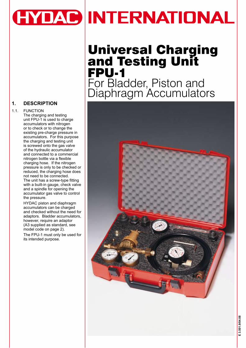
Universal Charging and Testing Unit FPU-1For Bladder, Piston and Diaphragm Accumulators
1. DESCRIPTION1.1. FUNCTION
The charging and testing unit FPU-1 is used to charge accumulators with nitrogen or to check or to change the existing pre-charge pressure in accumulators. For this purpose the charging and testing unit is screwed onto the gas valve of the hydraulic accumulator and connected to a commercial nitrogen bottle via a flexible charging hose. If the nitrogen pressure is only to be checked or reduced, the charging hose does not need to be connected. The unit has a screw-type fitting with a built-in gauge, check valve and a spindle for opening the accumulator gas valve to control the pressure.HYDAC piston and diaphragm accumulators can be charged and checked without the need for adaptors. Bladder accumulators, however, require an adaptor (A3 supplied as standard, see model code on page 2).The FPU-1 must only be used for its intended purpose.
E 3.
501.
9/04
.08
2
E 3.
501.
9/04
.08
2. TECHNICAL SPECIFICATIONS2.1. MODEL CODE
(also order example)FPU-1 250 F 2.5 G2 A1 K
Universal charging and testing unit
Gauge indication range 0 - 10 bar 0 - 145 psi 10 0 - 25 bar 0 - 363 psi 25 0 - 100 bar 0 - 1450 psi 100 0 - 250 bar 0 - 3626 psi 250 0 - 400 bar 0 - 5714 psi 400
Charging hose F = for 200 bar nitrogen bottle with connection W24.32x1/14 (DIN 477, Part 1) FM = for 300 bar nitrogen bottle with connection M30x1.5 (DIN 477, Part 5 to April 2002) FW = for 300 bar nitrogen bottle with connection W30x2 (DIN 477, Part 5 from April 2002)
Length of charging hose 2.5 m 2.5 4.0 m 4 Special lengths on request
Adaptor G for nitrogen bottles See table under point 10 (page 15)
Adaptor A A1 = M16x1.5 A2 = 5/8 - 18 UNF A3 = 7/8 - 14 UNF A4 = 7/8 - 14 UNF A5 = M8x1 A6 = G 3/4 A A7 = G 1/4 A8 = G 3/4 A9 = Vg 8 A10 = 7/8 - 14 UNF A11 = M16x2 D4 = 5/8 - 18 UNF (Part no. 366374)other adaptors on request
Protective case
Accessories (Please give full details when ordering.)Gas safety valve with intermediate piece (see point 5.3.).Pressure reducer (see point 5.1.). Adaptor for connector D (see point 4.1.). Wrench 14x15 (Part no. 1011065). Allen key SW6 (Part no. 1005164).Valve tool for gas valve (Part no. 616886).Torque wrench (Part no. 3136470)
(A3 is supplied as standard)
1.2. INTERVALS BETWEEN CHECKINGOn the whole, nitrogen losses on HYDAC hydraulic accumulators are very low. However, a regular check of the gas pre-charge pressure is recommended to prevent the piston from hitting the cover plate or the bladder or diaphragm from becoming too deformed, if there is a drop in the pressure p0.The pre-charge pressure p0 as shown on the label or the accumulator body, must be reset after every new installation or repair and then checked at least once during the following week. If no nitrogen loss is detected, a further check should be made after approx. 4 months. If after this period no change in the pressure is found, a yearly check should be sufficient.
1.3. CONSTRUCTIONThe HYDAC charging and testing unit for bladder, piston and diaphragm accumulators consists of:Valve body zSpindle zCheck valve zRelease valve zGauge zCharging hose zA3 adaptor for bladder zaccumulators
1.4. ACCESSORIESGas safety valve with zintermediate piece TUV set and lead sealed, it must be fitted between the hydraulic accumulator and the nitrogen bottle by means of the intermediate piece, if the gas pressure in the commercially available nitrogen bottle is higher than the max. permissible operating pressure of the hydraulic accumulator.Pressure reducer zfor setting the required pre-charge pressure between nitrogen bottle and accumulator.Protective case zfor storing the charging and testing unit and adaptors.
Different types of case are available, depending on customer requirement.
2.2. WEIGHTStandard model without case: approx. 1.4 kgStandard model with case: approx. 3.0 kg
3
E 3.
501.
9/04
.08
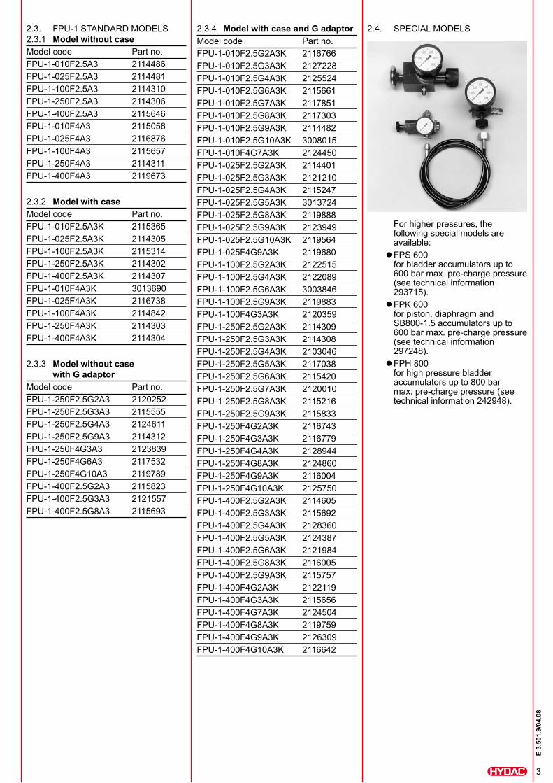
For higher pressures, the following special models are available:FPS 600 zfor bladder accumulators up to 600 bar max. pre-charge pressure (see technical information 293715).FPK 600 zfor piston, diaphragm and SB800-1.5 accumulators up to 600 bar max. pre-charge pressure (see technical information 297248).FPH 800 zfor high pressure bladder accumulators up to 800 bar max. pre-charge pressure (see technical information 242948).
2.3. FPU-1 STANDARD MODELS2.3.1 Model without caseModel code Part no.FPU-1-010F2.5A3 2114486FPU-1-025F2.5A3 2114481FPU-1-100F2.5A3 2114310FPU-1-250F2.5A3 2114306FPU-1-400F2.5A3 2115646FPU-1-010F4A3 2115056FPU-1-025F4A3 2116876FPU-1-100F4A3 2115657FPU-1-250F4A3 2114311FPU-1-400F4A3 2119673
2.3.2 Model with caseModel code Part no.FPU-1-010F2.5A3K 2115365FPU-1-025F2.5A3K 2114305FPU-1-100F2.5A3K 2115314FPU-1-250F2.5A3K 2114302FPU-1-400F2.5A3K 2114307FPU-1-010F4A3K 3013690FPU-1-025F4A3K 2116738FPU-1-100F4A3K 2114842FPU-1-250F4A3K 2114303FPU-1-400F4A3K 2114304
2.3.3 Model without case with G adaptor
Model code Part no.FPU-1-250F2.5G2A3 2120252FPU-1-250F2.5G3A3 2115555FPU-1-250F2.5G4A3 2124611FPU-1-250F2.5G9A3 2114312FPU-1-250F4G3A3 2123839FPU-1-250F4G6A3 2117532FPU-1-250F4G10A3 2119789FPU-1-400F2.5G2A3 2115823FPU-1-400F2.5G3A3 2121557FPU-1-400F2.5G8A3 2115693
2.3.4 Model with case and G adaptor Model code Part no.FPU-1-010F2.5G2A3K 2116766FPU-1-010F2.5G3A3K 2127228FPU-1-010F2.5G4A3K 2125524FPU-1-010F2.5G6A3K 2115661FPU-1-010F2.5G7A3K 2117851FPU-1-010F2.5G8A3K 2117303FPU-1-010F2.5G9A3K 2114482FPU-1-010F2.5G10A3K 3008015FPU-1-010F4G7A3K 2124450FPU-1-025F2.5G2A3K 2114401FPU-1-025F2.5G3A3K 2121210FPU-1-025F2.5G4A3K 2115247FPU-1-025F2.5G5A3K 3013724FPU-1-025F2.5G8A3K 2119888FPU-1-025F2.5G9A3K 2123949FPU-1-025F2.5G10A3K 2119564FPU-1-025F4G9A3K 2119680FPU-1-100F2.5G2A3K 2122515FPU-1-100F2.5G4A3K 2122089FPU-1-100F2.5G6A3K 3003846FPU-1-100F2.5G9A3K 2119883FPU-1-100F4G3A3K 2120359FPU-1-250F2.5G2A3K 2114309FPU-1-250F2.5G3A3K 2114308FPU-1-250F2.5G4A3K 2103046FPU-1-250F2.5G5A3K 2117038FPU-1-250F2.5G6A3K 2115420FPU-1-250F2.5G7A3K 2120010FPU-1-250F2.5G8A3K 2115216FPU-1-250F2.5G9A3K 2115833FPU-1-250F4G2A3K 2116743FPU-1-250F4G3A3K 2116779FPU-1-250F4G4A3K 2128944FPU-1-250F4G8A3K 2124860FPU-1-250F4G9A3K 2116004FPU-1-250F4G10A3K 2125750FPU-1-400F2.5G2A3K 2114605FPU-1-400F2.5G3A3K 2115692FPU-1-400F2.5G4A3K 2128360FPU-1-400F2.5G5A3K 2124387FPU-1-400F2.5G6A3K 2121984FPU-1-400F2.5G8A3K 2116005FPU-1-400F2.5G9A3K 2115757FPU-1-400F4G2A3K 2122119FPU-1-400F4G3A3K 2115656FPU-1-400F4G7A3K 2124504FPU-1-400F4G8A3K 2119759FPU-1-400F4G9A3K 2126309FPU-1-400F4G10A3K 2116642
2.4. SPECIAL MODELS
4
E 3.
501.
9/04
.08
3. OPERATING INSTRUCTIONS
3.1. TAKING ACCOUNT OF THE TEMPERATURE EFFECTIn order that the recommended pre-charge pressures are maintained even at relatively high operating temperatures, the pre-charge pressure p0 charge for charging and testing a cold accumulator must be selected as follows:
p0 charge= p0
Pre-charge temp. + 273Operating temp. + 273
Pre-charge temperature [°C] Operating temperature [°C]
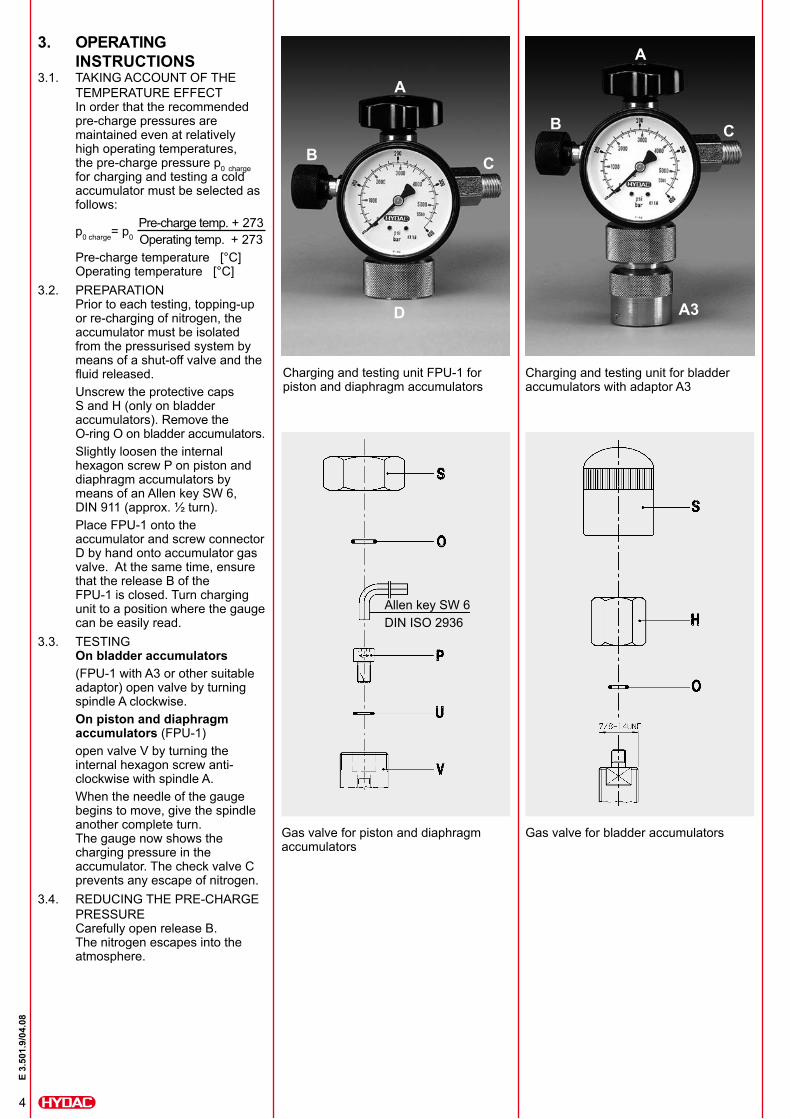
3.2. PREPARATIONPrior to each testing, topping-up or re-charging of nitrogen, the accumulator must be isolated from the pressurised system by means of a shut-off valve and the fluid released.Unscrew the protective caps S and H (only on bladder accumulators). Remove the O-ring O on bladder accumulators. Slightly loosen the internal hexagon screw P on piston and diaphragm accumulators by means of an Allen key SW 6, DIN 911 (approx. ½ turn). Place FPU-1 onto the accumulator and screw connector D by hand onto accumulator gas valve. At the same time, ensure that the release B of the FPU-1 is closed. Turn charging unit to a position where the gauge can be easily read.
3.3. TESTINGOn bladder accumulators(FPU-1 with A3 or other suitable adaptor) open valve by turning spindle A clockwise.On piston and diaphragm accumulators (FPU-1)open valve V by turning the internal hexagon screw anti-clockwise with spindle A.When the needle of the gauge begins to move, give the spindle another complete turn. The gauge now shows the charging pressure in the accumulator. The check valve C prevents any escape of nitrogen.
3.4. REDUCING THE PRE-CHARGE PRESSURECarefully open release B. The nitrogen escapes into the atmosphere.
Allen key SW 6DIN ISO 2936
Charging and testing unit FPU-1 for piston and diaphragm accumulators
Charging and testing unit for bladder accumulators with adaptor A3
Gas valve for piston and diaphragm accumulators
Gas valve for bladder accumulators
A
A
B C
B C
D A3
5
E 3.
501.
9/04
.08
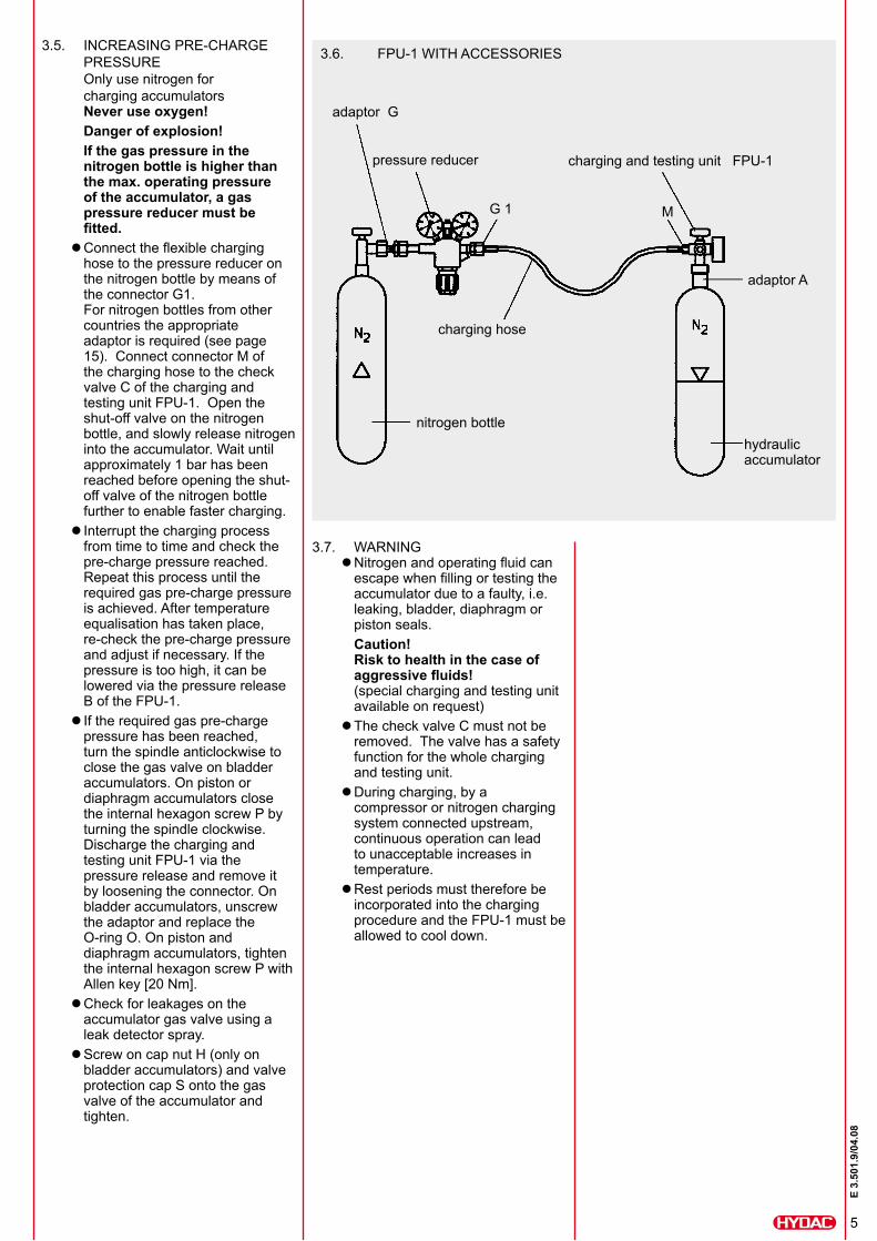
3.6. FPU-1 WITH ACCESSORIES
adaptor G
pressure reducer
G 1 M
charging and testing unit FPU-1
nitrogen bottlehydraulic accumulator
adaptor A
3.5. INCREASING PRE-CHARGE PRESSURE
Only use nitrogen for charging accumulatorsNever use oxygen!Danger of explosion!If the gas pressure in the nitrogen bottle is higher than the max. operating pressure of the accumulator, a gas pressure reducer must be fitted.Connect the flexible charging zhose to the pressure reducer on the nitrogen bottle by means of the connector G1. For nitrogen bottles from other countries the appropriate adaptor is required (see page 15). Connect connector M of the charging hose to the check valve C of the charging and testing unit FPU-1. Open the shut-off valve on the nitrogen bottle, and slowly release nitrogen into the accumulator. Wait until approximately 1 bar has been reached before opening the shut-off valve of the nitrogen bottle further to enable faster charging.Interrupt the charging process zfrom time to time and check the pre-charge pressure reached. Repeat this process until the required gas pre-charge pressure is achieved. After temperature equalisation has taken place, re-check the pre-charge pressure and adjust if necessary. If the pressure is too high, it can be lowered via the pressure release B of the FPU-1.If the required gas pre-charge zpressure has been reached, turn the spindle anticlockwise to close the gas valve on bladder accumulators. On piston or diaphragm accumulators close the internal hexagon screw P by turning the spindle clockwise. Discharge the charging and testing unit FPU-1 via the pressure release and remove it by loosening the connector. On bladder accumulators, unscrew the adaptor and replace the O-ring O. On piston and diaphragm accumulators, tighten the internal hexagon screw P with Allen key [20 Nm].Check for leakages on the zaccumulator gas valve using a leak detector spray.Screw on cap nut H (only on zbladder accumulators) and valve protection cap S onto the gas valve of the accumulator and tighten.
charging hose
3.7. WARNINGNitrogen and operating fluid can zescape when filling or testing the accumulator due to a faulty, i.e. leaking, bladder, diaphragm or piston seals.Caution! Risk to health in the case of aggressive fluids! (special charging and testing unit available on request)The check valve C must not be zremoved. The valve has a safety function for the whole charging and testing unit.During charging, by a zcompressor or nitrogen charging system connected upstream, continuous operation can lead to unacceptable increases in temperature.Rest periods must therefore be zincorporated into the charging procedure and the FPU-1 must be allowed to cool down.
6
E 3.
501.
9/04
.08
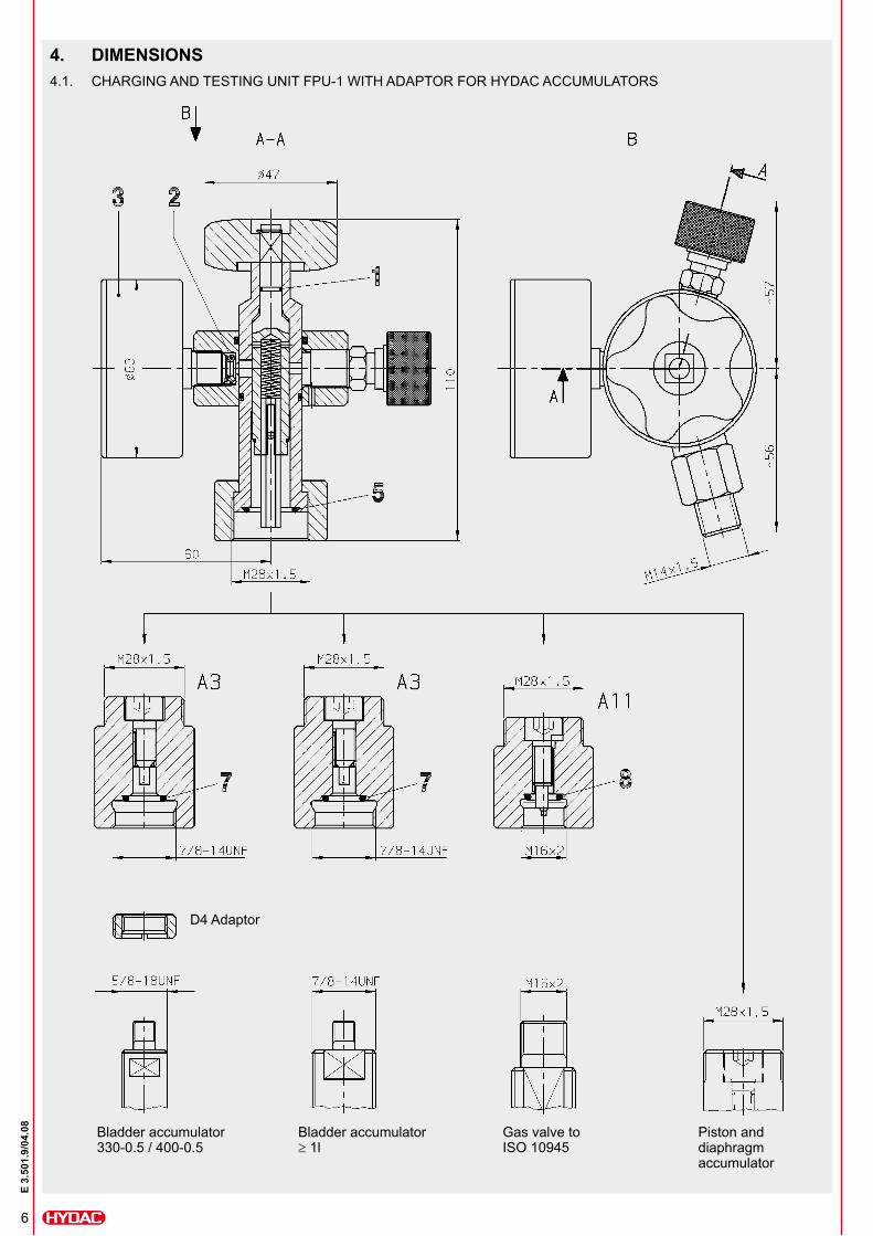
4. DIMENSIONS4.1. CHARGING AND TESTING UNIT FPU-1 WITH ADAPTOR FOR HYDAC ACCUMULATORS
Bladder accumulator 330-0.5 / 400-0.5
Bladder accumulator ≥ 1l
Gas valve to ISO 10945
Piston and diaphragm accumulator
D4 Adaptor
7
E 3.
501.
9/04
.08
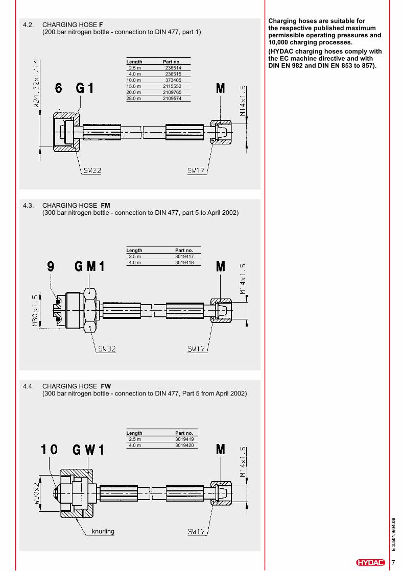
4.2. CHARGING HOSE F(200 bar nitrogen bottle - connection to DIN 477, part 1)
Length Part no. 2.5 m 236514 4.0 m 23651510.0 m 37340515.0 m 211555220.0 m 210976528.0 m 2109574
4.3. CHARGING HOSE FM(300 bar nitrogen bottle - connection to DIN 477, part 5 to April 2002)
Length Part no. 2.5 m 3019417 4.0 m 3019418
4.4. CHARGING HOSE FW(300 bar nitrogen bottle - connection to DIN 477, Part 5 from April 2002)
Length Part no. 2.5 m 3019419 4.0 m 3019420
Charging hoses are suitable for the respective published maximum permissible operating pressures and 10,000 charging processes.(HYDAC charging hoses comply with the EC machine directive and with DIN EN 982 and DIN EN 853 to 857).
knurling
8
E 3.
501.
9/04
.08
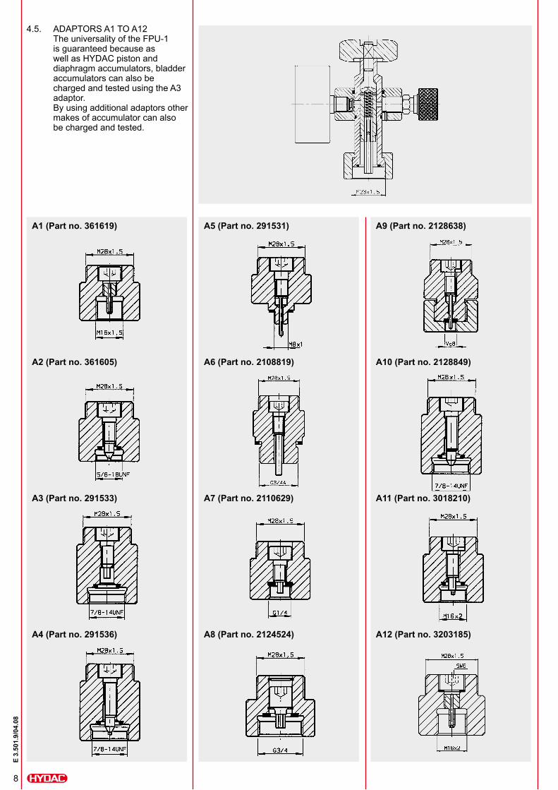
4.5. ADAPTORS A1 TO A12The universality of the FPU-1 is guaranteed because as well as HYDAC piston and diaphragm accumulators, bladder accumulators can also be charged and tested using the A3 adaptor. By using additional adaptors other makes of accumulator can also be charged and tested.
A1 (Part no. 361619)
A2 (Part no. 361605)
A3 (Part no. 291533)
A4 (Part no. 291536)
A5 (Part no. 291531)
A6 (Part no. 2108819)
A7 (Part no. 2110629)
A8 (Part no. 2124524)
A9 (Part no. 2128638)
A10 (Part no. 2128849)
A11 (Part no. 3018210)
A12 (Part no. 3203185)
9
E 3.
501.
9/04
.08
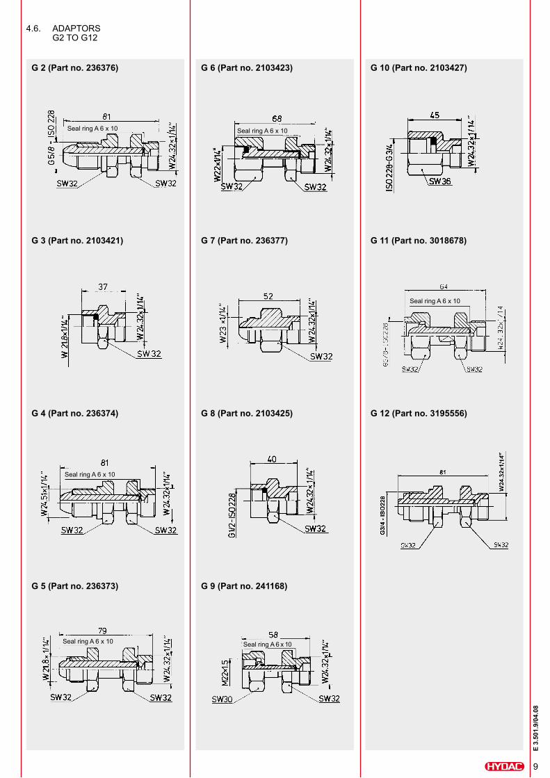
G 10 (Part no. 2103427)
G 11 (Part no. 3018678)
G 12 (Part no. 3195556)
G 6 (Part no. 2103423)
G 7 (Part no. 236377)
G 8 (Part no. 2103425)
G 9 (Part no. 241168)
G 2 (Part no. 236376)
G 3 (Part no. 2103421)
G 4 (Part no. 236374)
G 5 (Part no. 236373)
4.6. ADAPTORS G2 TO G12
Seal ring A 6 x 10
Seal ring A 6 x 10
Seal ring A 6 x 10
Seal ring A 6 x 10
Seal ring A 6 x 10
Seal ring A 6 x 10
10
E 3.
501.
9/04
.08
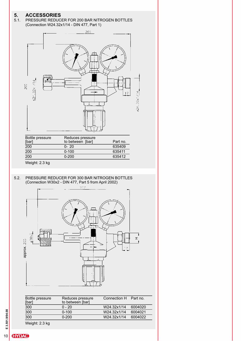
5. ACCESSORIES5.1. PRESSURE REDUCER FOR 200 BAR NITROGEN BOTTLES
(Connection W24.32x1/14 - DIN 477, Part 1)
Bottle pressure Reduces pressure [bar] to between [bar] Part no.200 0- 20 635409200 0-100 635411200 0-200 635412Weight: 2.3 kg
5.2. PRESSURE REDUCER FOR 300 BAR NITROGEN BOTTLES (Connection W30x2 - DIN 477, Part 5 from April 2002)
Bottle pressure Reduces pressure Connection H Part no. [bar] to between [bar]300 0 - 20 W24.32x1/14 6004020300 0-100 W24.32x1/14 6004021300 0-200 W24.32x1/14 6004022Weight: 2.3 kg
appr
ox.
11
E 3.
501.
9/04
.08
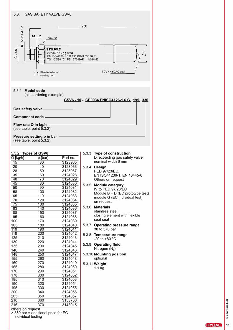
5.3. GAS SAFETY VALVE GSV6
Q [kg/h] p [bar] Part no. 15 30 3123965 20 40 3123966 28 50 3123967 35 60 3124028 40 70 3124029 45 80 3124030 50 90 3124031 58 100 3124032 65 110 3124033 70 120 3124034 75 130 3124035 83 140 3124036 88 150 3124037 95 160 3124038100 170 3124039105 180 3124040110 190 3124041118 200 3124042125 210 3124043130 220 3124044135 230 3124045140 240 3124046148 250 3124047155 260 3124048160 270 3124049165 280 3124050170 290 3124051178 300 3124052185 310 3124053190 320 3124054195 330 3124055200 340 3124056205 350 3124057210 360 3153706216 370 3143015others on request > 350 bar = additional price for EC individual testing
Steel/elastomer sealing ring
TÜV / HYDAC seal
hex. 32
GSV6 - 10 - 0034 EN ISO 4126-1.6.G.195 KG/H 330 BAR TS -20/80 °C PS 370 BAR 14/03/452
5.3.1 Model code(also ordering example)
GSV6 - 10 - CE0034.ENISO4126-1.6.G. 195. 330
Gas safety valve
Component code
Flow rate Q in kg/h(see table, point 5.3.2)
Pressure setting p in bar(see table, point 5.3.2)
5.3.2 Types of GSV6 5.3.3 Type of constructionDirect-acting gas safety valve nominal width 6 mm
5.3.4 DesignPED 97/23/EC, EN ISO41236-1, EN 13445-6 Others on request
5.3.5 Module categoryIV to PED 97/23/EC Module B + D (EC prototype test) module G (EC individual test) on request
5.3.6 Materials stainless steel, closing element with flexible seat seal
5.3.7 Operating pressure range30 to 370 bar
5.3.8 Temperature range-20 to +80 °C
5.3.9 Operating fluidNitrogen (N2)
5.3.10 Mounting positionoptional
5.3.11 Weight1.1 kg
12
E 3.
501.
9/04
.08
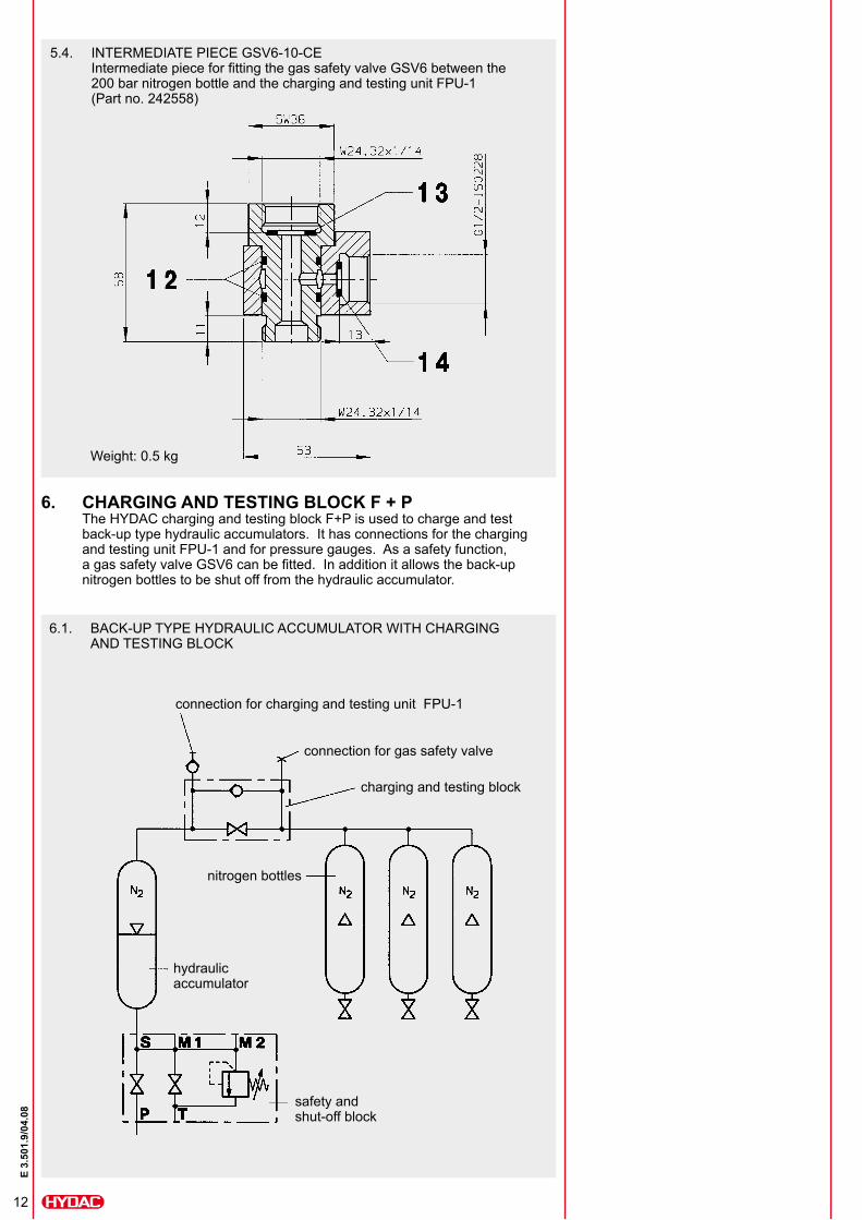
6. CHARGING AND TESTING BLOCK F + PThe HYDAC charging and testing block F+P is used to charge and test back-up type hydraulic accumulators. It has connections for the charging and testing unit FPU-1 and for pressure gauges. As a safety function, a gas safety valve GSV6 can be fitted. In addition it allows the back-up nitrogen bottles to be shut off from the hydraulic accumulator.
6.1. BACK-UP TYPE HYDRAULIC ACCUMULATOR WITH CHARGING AND TESTING BLOCK
nitrogen bottles
hydraulic accumulator
safety and shut-off block
charging and testing block
connection for gas safety valve
connection for charging and testing unit FPU-1
5.4. INTERMEDIATE PIECE GSV6-10-CEIntermediate piece for fitting the gas safety valve GSV6 between the 200 bar nitrogen bottle and the charging and testing unit FPU-1 (Part no. 242558)
Weight: 0.5 kg
13
E 3.
501.
9/04
.08
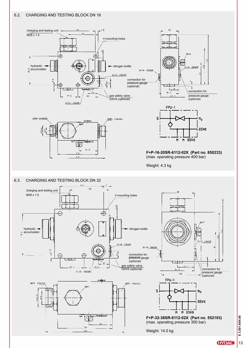
6.2. CHARGING AND TESTING BLOCK DN 16
F+P-16-20SR-6112-02X (Part no. 850233) (max. operating pressure 400 bar) Weight: 4.3 kg
charging and testing unit M28 x 1.5
4 mounting holes
hydraulic accumulator
nitrogen bottle
gas safety valve GSV6 (optional)
connection for pressure gauge (optional)
connection for pressure gauge (optional)
6.3. CHARGING AND TESTING BLOCK DN 32
F+P-32-38SR-6112-02X (Part no. 552193) (max. operating pressure 350 bar) Weight: 14.0 kg
charging and testing unit M28 x 1.5 4 mounting holes
hydraulic accumulator
nitrogen bottle
gas safety valve GSV6 (optional) connection for
pressure gauge (optional)
connection for pressure gauge (optional)
14
E 3.
501.
9/04
.08
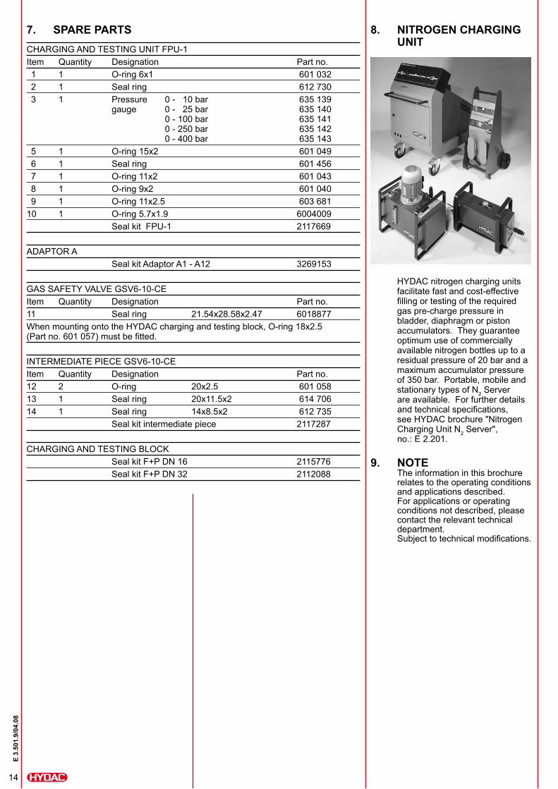
7. SPARE PARTSCHARGING AND TESTING UNIT FPU-1Item Quantity Designation Part no. 1 1 O-ring 6x1 601 032 2 1 Seal ring 612 730 3 1 Pressure 0 - 10 bar 635 139 gauge 0 - 25 bar 635 140 0 - 100 bar 635 141 0 - 250 bar 635 142 0 - 400 bar 635 143 5 1 O-ring 15x2 601 049 6 1 Seal ring 601 456 7 1 O-ring 11x2 601 043 8 1 O-ring 9x2 601 040 9 1 O-ring 11x2.5 603 68110 1 O-ring 5.7x1.9 6004009 Seal kit FPU-1 2117669
ADAPTOR A Seal kit Adaptor A1 - A12 3269153
GAS SAFETY VALVE GSV6-10-CEItem Quantity Designation Part no. 11 Seal ring 21.54x28.58x2.47 6018877When mounting onto the HYDAC charging and testing block, O-ring 18x2.5 (Part no. 601 057) must be fitted.
INTERMEDIATE PIECE GSV6-10-CEItem Quantity Designation Part no.12 2 O-ring 20x2.5 601 05813 1 Seal ring 20x11.5x2 614 70614 1 Seal ring 14x8.5x2 612 735 Seal kit intermediate piece 2117287
CHARGING AND TESTING BLOCK Seal kit F+P DN 16 2115776 Seal kit F+P DN 32 2112088
HYDAC nitrogen charging units facilitate fast and cost-effective filling or testing of the required gas pre-charge pressure in bladder, diaphragm or piston accumulators. They guarantee optimum use of commercially available nitrogen bottles up to a residual pressure of 20 bar and a maximum accumulator pressure of 350 bar. Portable, mobile and stationary types of N2 Server are available. For further details and technical specifications, see HYDAC brochure "Nitrogen Charging Unit N2 Server", no.: E 2.201.
9. NOTEThe information in this brochure relates to the operating conditions and applications described. For applications or operating conditions not described, please contact the relevant technical department.Subject to technical modifications.
8. NITROGEN CHARGING UNIT
15
E 3.
501.
9/04
.08
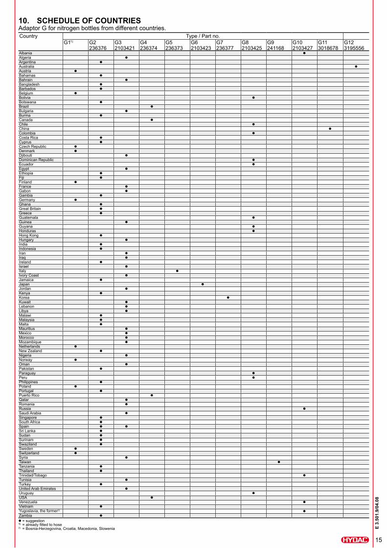
10. SCHEDULE OF COUNTRIESAdaptor G for nitrogen bottles from different countries.Country Type / Part no.
G11) G2 G3 G4 G5 G6 G7 G8 G9 G10 G11 G12236376 2103421 236374 236373 2103423 236377 2103425 241168 2103427 3018678 3195556
Albania zAlgeria zArgentina zAustralia zAustria zBahamas zBahrain zBangladesh zBarbados zBelgium zBolivia zBotswana zBrazil zBulgaria zBurma zCanada zChile zChina zColombia zCosta Rica zCyprus zCzech Republic zDenmark zDjibouti zDominican Republic zEcuador zEgypt zEthiopia zFiji zFinland zFrance zGabon zGambia zGermany zGhana zGreat Britain zGreece zGuatemala zGuinea zGuyana zHonduras zHong Kong zHungary zIndia zIndonesia zIran zIraq zIreland zIsrael zItaly zIvory Coast zJamaica zJapan zJordan zKenya zKorea zKuwait zLebanon zLibya zMalawi zMalaysia zMalta zMauritius zMexico zMorocco zMozambique zNetherlands zNew Zealand zNigeria zNorway zOman zPakistan zParaguay zPeru zPhilippines zPoland zPortugal zPuerto Rico zQatar zRomania zRussia zSaudi Arabia zSingapore zSouth Africa zSpain z zSri Lanka zSudan zSurinam zSwaziland zSweden zSwitzerland zSyria zTaiwan zTanzania zThailand zTrinidad/Tobago zTunisia zTurkey zUnited Arab Emirates zUruguay zUSA zVenezuela zVietnam zYugoslavia, the former2) zZambia zz = suggestion 1) = already fitted to hose 2) = Bosnia-Herzegovina, Croatia, Macedonia, Slowenia