Embed Size (px)
DESCRIPTION
A tutorial on wind dynamics
Citation preview
A Tutorial on the Dynamics and Control
of Wind Turbines and Wind Farms
Lucy Y. Pao and Kathryn E. Johnson
Abstract— Wind energy is currently the fastest-growing en-ergy source in the world, with a concurrent growth in demandfor the expertise of engineers and researchers in the wind energyfield. There are still many unsolved challenges in expandingwind power, and there are numerous problems of interest tosystems and control researchers. In this paper, we first reviewthe basic structure of wind turbines and then describe windturbine control systems and control loops. Of great interest arethe generator torque and blade pitch control systems, wheresignificant performance improvements are achievable with moreadvanced systems and control research. We describe recentdevelopments in advanced controllers for wind turbines andwind farms, and we also outline many open problems in theareas of modeling and control of wind turbines.
I. INTRODUCTION
Wind energy is a fast-growing interdisciplinary field that
encompasses many different branches of engineering and
science. According to the American Wind Energy Associ-
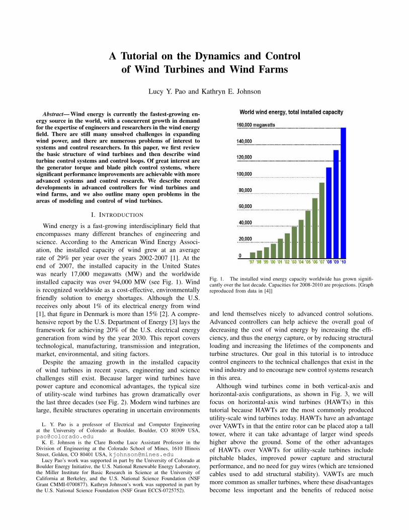
ation, the installed capacity of wind grew at an average
rate of 29% per year over the years 2002-2007 [1]. At the
end of 2007, the installed capacity in the United States
was nearly 17,000 megawatts (MW) and the worldwide
installed capacity was over 94,000 MW (see Fig. 1). Wind
is recognized worldwide as a cost-effective, environmentally
friendly solution to energy shortages. Although the U.S.
receives only about 1% of its electrical energy from wind
[1], that figure in Denmark is more than 15% [2]. A compre-
hensive report by the U.S. Department of Energy [3] lays the
framework for achieving 20% of the U.S. electrical energy
generation from wind by the year 2030. This report covers
technological, manufacturing, transmission and integration,
market, environmental, and siting factors.
Despite the amazing growth in the installed capacity
of wind turbines in recent years, engineering and science
challenges still exist. Because larger wind turbines have
power capture and economical advantages, the typical size
of utility-scale wind turbines has grown dramatically over
the last three decades (see Fig. 2). Modern wind turbines are
large, flexible structures operating in uncertain environments
L. Y. Pao is a professor of Electrical and Computer Engineeringat the University of Colorado at Boulder, Boulder, CO 80309 USA,[email protected]
K. E. Johnson is the Clare Boothe Luce Assistant Professor in theDivision of Engineering at the Colorado School of Mines, 1610 IllinoisStreet, Golden, CO 80401 USA, [email protected]
Lucy Pao’s work was supported in part by the University of Colorado atBoulder Energy Initiative, the U.S. National Renewable Energy Laboratory,the Miller Institute for Basic Research in Science at the University ofCalifornia at Berkeley, and the U.S. National Science Foundation (NSFGrant CMMI-0700877). Kathryn Johnson’s work was supported in part bythe U.S. National Science Foundation (NSF Grant ECCS-0725752).
Fig. 1. The installed wind energy capacity worldwide has grown signifi-cantly over the last decade. Capacities for 2008-2010 are projections. [Graphreproduced from data in [4]]
and lend themselves nicely to advanced control solutions.
Advanced controllers can help achieve the overall goal of
decreasing the cost of wind energy by increasing the effi-
ciency, and thus the energy capture, or by reducing structural
loading and increasing the lifetimes of the components and
turbine structures. Our goal in this tutorial is to introduce
control engineers to the technical challenges that exist in the
wind industry and to encourage new control systems research
in this area.
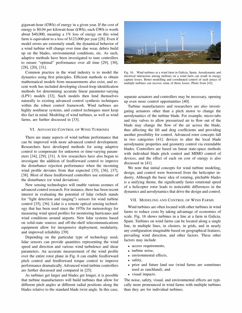
Although wind turbines come in both vertical-axis and
horizontal-axis configurations, as shown in Fig. 3, we will
focus on horizontal-axis wind turbines (HAWTs) in this
tutorial because HAWTs are the most commonly produced
utility-scale wind turbines today. HAWTs have an advantage
over VAWTs in that the entire rotor can be placed atop a tall
tower, where it can take advantage of larger wind speeds
higher above the ground. Some of the other advantages
of HAWTs over VAWTs for utility-scale turbines include
pitchable blades, improved power capture and structural
performance, and no need for guy wires (which are tensioned
cables used to add structural stability). VAWTs are much
more common as smaller turbines, where these disadvantages
become less important and the benefits of reduced noise
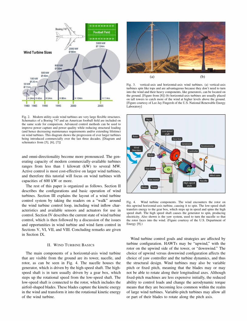
Fig. 2. Modern utility-scale wind turbines are very large flexible structures.Schematics of a Boeing 747 and an American football field are included onthe same scale for comparison. Advanced control methods can be used toimprove power capture and power quality while reducing structural loading(and hence decreasing maintenance requirements and/or extending lifetime)on wind turbines. This diagram shows the progression of ever larger turbinesbeing introduced commercially over the last three decades. [Diagram andschematics from [5], [6], [7]]
and omni-directionality become more pronounced. The gen-
erating capacity of modern commercially-available turbines
ranges from less than 1 kilowatt (kW) to several MW.
Active control is most cost-effective on larger wind turbines,
and therefore this tutorial will focus on wind turbines with
capacities of 600 kW or more.
The rest of this paper is organized as follows. Section II
describes the configurations and basic operation of wind
turbines. Section III explains the layout of a wind turbine
control system by taking the readers on a “walk” around
the wind turbine control loop, including wind inflow char-
acteristics and available sensors and actuators for use in
control. Section IV describes the current state of wind turbine
control, which is then followed by a discussion of the issues
and opportunities in wind turbine and wind farm control in
Sections V, VI, VII, and VIII. Concluding remarks are given
in Section IX.
II. WIND TURBINE BASICS
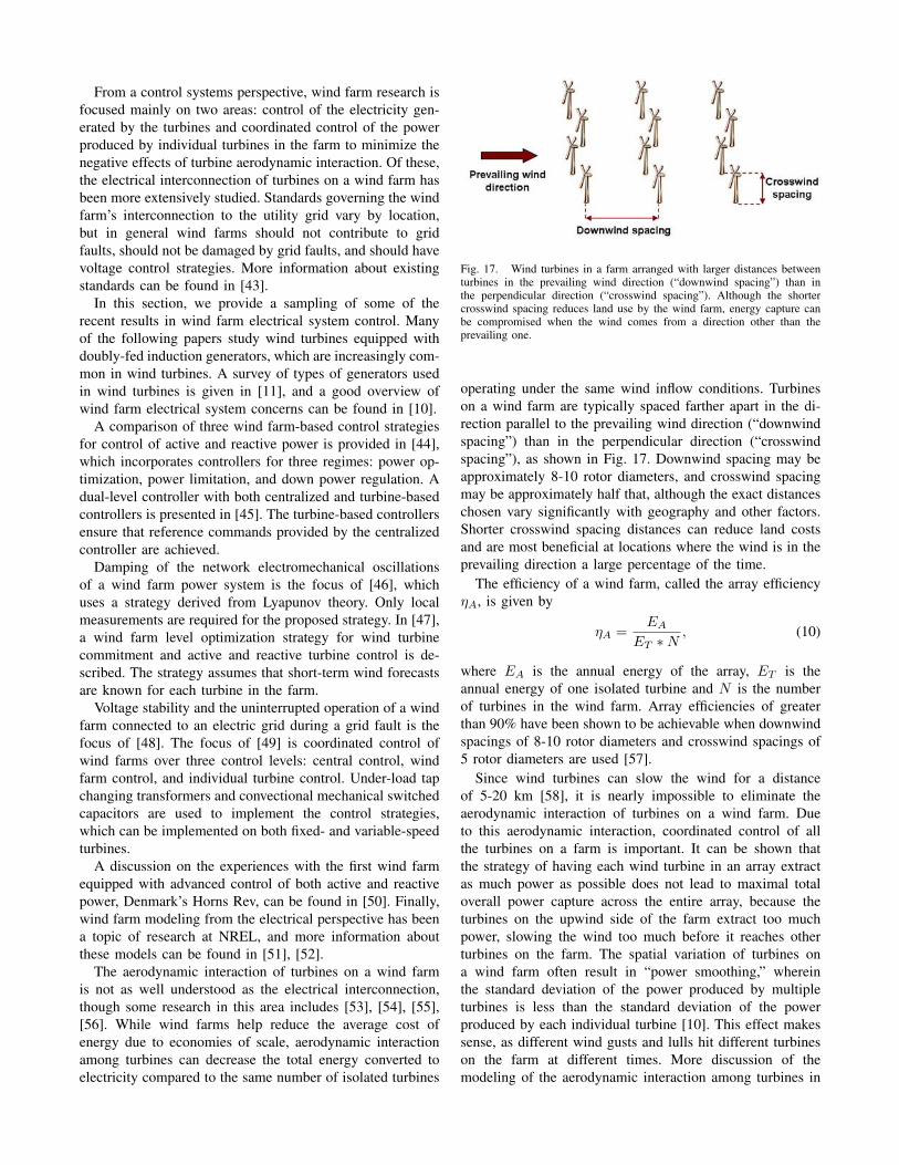
The main components of a horizontal-axis wind turbine
that are visible from the ground are its tower, nacelle, and
rotor, as can be seen in Fig. 4. The nacelle houses the
generator, which is driven by the high-speed shaft. The high-
speed shaft is in turn usually driven by a gear box, which
steps up the rotational speed from the low-speed shaft. The
low-speed shaft is connected to the rotor, which includes the
airfoil-shaped blades. These blades capture the kinetic energy
in the wind and transform it into the rotational kinetic energy
of the wind turbine.
(a) (b)
Fig. 3. vertical-axis and horizontal-axis wind turbines. (a) vertical-axisturbines spin like tops and are advantageous because they don’t need to turninto the wind and their heavy components, like generators, can be located onthe ground. [Figure from [8]] (b) horizontal-axis turbines are usually placedon tall towers to catch more of the wind at higher levels above the ground.[Figure courtesy of Lee Jay Fingersh of the U.S. National Renewable EnergyLaboratory]
Fig. 4. Wind turbine components. The wind encounters the rotor onthis upwind horizontal-axis turbine, causing it to spin. The low-speed shafttransfers energy to the gear box, which steps up in speed and spins the highspeed shaft. The high speed shaft causes the generator to spin, producingelectricity. Also shown is the yaw system, used to turn the nacelle so thatthe rotor faces into the wind. (Figure courtesy of the U.S. Department ofEnergy [9].)
Wind turbine control goals and strategies are affected by
turbine configuration. HAWTs may be “upwind,” with the
rotor on the upwind side of the tower, or “downwind.” The
choice of upwind versus downwind configuration affects the
choice of yaw controller and the turbine dynamics, and thus
the structural design. Wind turbines may also be variable
pitch or fixed pitch, meaning that the blades may or may
not be able to rotate along their longitudinal axes. Although
fixed-pitch machines are less expensive initially, the reduced
ability to control loads and change the aerodynamic torque
means that they are becoming less common within the realm
of large wind turbines. Variable-pitch turbines may allow all
or part of their blades to rotate along the pitch axis.

Fig. 5. Example power curves. The “Wind Power” curve shows the poweravailable in the wind for a turbine of the same size as the two exampleturbines. Note that the example turbines produce no power in low windsbecause they are not turned on until the wind speed reaches a certain level.Further, power is limited to protect the electrical and mechanical componentsof both turbines in high wind speeds. Both turbines produce the same powerat the design point for the fixed speed turbine, but the variable speed turbineproduces more power over the rest of Region 2.
Moreover, wind turbines can be variable speed or fixed
speed. Variable-speed turbines tend to operate closer to their
maximum aerodynamic efficiency for a higher percentage of
the time, but require electrical power processing so that the
generated electricity can be fed into the electrical grid at the
proper frequency. As generator and power electronics tech-
nologies improve and costs decrease, variable-speed turbines
are becoming more popular than constant-speed turbines at
the utility scale.
Fig. 5 shows example power curves for a variable-speed
and a fixed-speed wind turbine, as well as a curve showing
the power available in the wind for this 2.5 MW example
turbine. For both turbines, when the wind speed is low (in
this case, below 6 m/s), the power available in the wind is
low compared to losses in the turbine system so the turbines
are not run. This operational region is sometimes known as
Region 1. When the wind speed is high, Region 3 (above
11.7 m/s in this example), power is limited for both turbines
to avoid exceeding safe electrical and mechanical load limits.
The main difference in Fig. 5 between the two types of
turbines appears for mid-range wind speeds, Region 2, which
encompasses wind speeds between 6 and 11.7 m/s in this
example. Except for one design operating point (10 m/s
in this example), the variable-speed turbine captures more
power than the fixed-speed turbine. The reason for the
discrepancy is that variable-speed turbines can operate at
maximum aerodynamic efficiency over a wider range of wind
speeds than fixed-speed turbines. The maximum difference
between the two curves in Region 2 is 150 kW. For a typical
wind speed distribution with a Weibull distribution [10], [11]
having a shape parameter k = 2 and scale parameter c = 8.5,
the variable-speed turbine captures 2.3% more energy per
year than the constant-speed turbine, which is considered to
be a significant difference in the wind industry.
Not shown in Fig. 5 is the “high wind cut-out,” a wind
speed above which the turbine is powered down and stopped
to avoid excessive operating loads. High wind cut-out typ-
ically occurs at wind speeds above 20 - 30 m/s for large
turbines, with many factors determining the exact value.
Even a perfect wind turbine cannot fully capture the power
available in the wind. In fact, actuator disc theory shows
that the theoretical maximum aerodynamic efficiency, which
is called the Betz Limit, is approximately 59% of the wind
power [12]. The reason that an efficiency of 100% cannot
be achieved is that the wind must have some kinetic energy
remaining after passing through the rotor disc; if it did not,
the wind would by definition be stopped and no more wind
would be able to pass through the rotor to provide energy to
the turbine.
The aerodynamic efficiency is the ratio of turbine power to
wind power and is known as the turbine’s power coefficient,
Cp. Cp can be computed as
Cp =P
Pwind
, (1)
where P is the power captured by the turbine and Pwind is
the power available in the wind for a turbine of that size.
The power Pwind is given by
Pwind =1
2ρAv3, (2)
where ρ is the air density, A is the ‘swept area’ of the rotor,
and v is the instantaneous wind speed. The swept area is
the circle described by the blade tip, or πR2, where R is
the rotor radius. In (2), the wind speed v is assumed to be
uniform across the rotor swept area.
References [10] and [11] are excellent sources for more
detailed information about many aspects of wind turbines.
III. A WALK AROUND THE WIND TURBINE CONTROL
LOOPS
In designing controllers for wind turbines, it is often
assumed (as in (2)) that the wind speed is uniform across
the rotor plane. However, as shown by the “instantaneous
wind field” in Fig. 6, the wind input can vary substantially
in space and time as it approaches the rotor plane. The
deviations of the wind speed from the expected nominal wind
speed across the rotor plane are considered disturbances for
control design. It is virtually impossible to obtain a good
measurement of the wind speed encountering the blades
because of the spatial and temporal variability and also
because the rotor interacts with and changes the wind input.
Not only does turbulent wind cause the wind to be different
for the different blades, but the wind speed input is different
at different positions along each blade.
Utility-scale wind turbines have several levels of con-
trol, which can be called ‘supervisory control,’ ‘operational
control,’ and ‘subsystem control.’ The top-level supervisory
control determines when the turbine starts and stops in
response to changes in the wind speed, and also monitors
the health of the turbine. The operational control determines

Fig. 6. A Wind Turbine Control Block Diagram. The diagram shows that the speed of the wind that hits the turbine can vary significantly across therotor plane. Rotor speed measurements are usually the only measurements used in the feedback loops for both the generator torque control and the bladepitch control.
how the turbine achieves its control objectives in Regions 2
and 3. The subsystem controllers cause the generator, power
electronics, yaw drive, pitch drive, and other actuators to
perform as desired. In this section, we will move through
the operational control loops shown in Fig. 6, describing
the wind inflow, sensors, and actuators in more detail while
treating the subsystem controllers as black boxes. The pitch
and torque controllers in Fig. 6 will be discussed further
in Section IV. The details of the subsystem controllers are
beyond the scope of this paper, and the reader is referred
to [10], [11] for an overview of these lower-level controllers.
A. Wind Inflow
The differential heating of the earth’s atmosphere is the
driving mechanism for the earth’s winds. Numerous atmo-
spheric phenomena, such as the nocturnal low-level jet, sea
breezes, frontal passages, and mountain and valley flows, af-
fect the wind inflow across a wind turbine’s rotor plane [10].
From Fig. 2, the rotor plane of modern megawatt utility-scale
wind turbines span from 60 m to 180 m above the ground.
Given this large size of wind turbine rotor planes, and the
variability of wind, it is virtually impossible to obtain a good
measurement of the wind speed encountering the entire span
of the blades from in situ sensors mounted on the nacelle or
turbine blades. Current and future technologies for measuring
wind inflow to a turbine will be discussed in Sections III-B
and VI, respectively.
The available wind resource is often characterized by
the average wind speed, the frequency distribution of wind
speeds, the temporal and spatial variation in wind speed, the
most frequent wind direction (i.e., prevailing wind direction),
and the frequency of other wind directions [10]. How con-
sistently the wind blows above the rated wind speed for a
given turbine will determine how often the turbine will be
operating in Region 3 at its maximum rated power generation
capacity. The capacity factor is the ratio of a wind turbine’s
(or wind farm’s) energy output over a period of time to the
amount of energy the turbine would have produced if it had
run at full capacity for the same amount of time:
Capacity Factor =actual energy output over time period
energy output if turbine operatedat max output over same time period
To accurately predict capacity factors and maintenance
requirements for wind turbines, it is important to be able
to understand wind characteristics over long (multi-year)
as well as short (second and sub-second) time scales. The
ability to measure and predict the available wind resource
at a particular site is important in determining whether that
location is suitable and economically advantageous for siting
wind turbines. Significant variations in seasonal average
wind speeds are common and affect a local area’s available
wind resource over the course of each year. Large wind
speed and direction variations also occur on a diurnal (or
daily) time scale. Diurnal wind variation is caused by the
differential heating of the earth’s surface during the daily
solar radiation cycle. Being able to accurately predict hourly
wind speed variations is important for utilities to properly
plan their energy resource portfolio mix of wind energy
with other sources of energy. Finally, knowledge of short-
term wind speed variations, such as gusts and turbulence,
is important in both turbine and control design processes so
that structural loading can be mitigated during these events.
Although wind inflow characteristics are dynamic and

Fig. 7. High-resolution Doppler Lidar measurements showing coherentturbulent kinetic energy (TKE), which may cause excessive loading on awind turbine. Note that the majority of the TKE occurs between 40 - 120m, which is a typical range for a utility-scale turbine rotor. Reproduced withpermission from [13].
variable across the turbine’s rotor plane, nearly all modeling,
design, and control is based on assumptions of uniform and
constant wind across the rotor plane, including equations (1)-
(2) above (as well all other equations in the remainder of this
paper). While this assumption simplifies models and hence
the design and control of wind turbines, as wind turbines
become larger, the variability of the wind across the rotor
plane makes this uniform wind assumption more and more
erroneous. This assumption is leading to poor predictions of
both the available wind power and loading and wear on the
turbine due to the wind. This latter is becoming especially
problematic as realistic nocturnal low-level jets (which are
non-uniform winds) are leading to much higher levels of
maintenance and repair on significantly large numbers of
commercial turbines than predicted based on uniform wind
assumptions.
Random turbulent structures have always existed in the
wind resource throughout history. In past decades, when
turbines were smaller and placed atop shorter towers, the
effects of these structures hitting the turbines was either not
well understood, or was less significant than it is becoming
with more modern turbines. Today’s larger turbines are often
hit with turbulent structures that are comparable or smaller in
size than turbine rotor planes, and recent analysis indicates
that turbulent structures smaller than the rotor cause more
damage than those larger than the rotor. This effect may
stem from the fact that smaller structures cause very different
wind conditions to “hit” different blades of a large turbine,
causing serious fatigue and extreme loading issues that can
cause excessive wear or damage to the turbine structure [14].
Better capabilities for measuring and predicting turbulent
events are needed [15], and this is an active area of research
among atmospheric scientists. Fig. 7 shows measurements of
coherent turbulent kinetic energy (TKE) in a low-level jet, a
common atmospheric feature in some parts of the US. There
are significant energetic structures located between 40 - 120
m above ground level, the typical height for modern utility-
scale turbine rotors. Turbulent structures may take many
forms, with one example being wind velocity appearing like
Fig. 8. Several types of sonic and propeller anemometers on a meteorologi-cal tower at the National Renewable Energy Laboratory’s (NREL’s) NationalWind Technology Center (NWTC) near Boulder, Colorado. Anemometerson commercial wind turbines are typically placed on the nacelle.
a log rolling toward the turbine (higher velocity at the top,
and lower or even negative velocity at the bottom). Con-
trollers designed to alleviate structural loading in response
to turbulent structures are described in [16].
B. Sensors
A typical commercial wind turbine has surprisingly few
sensors for its size and complexity. As shown in Fig. 6, only
rotor speed measurements are typically used in feedback for
basic control in both Region 2 and Region 3. Since the gear
box ratio is known, speed can be measured on either the high
speed (generator) or low speed (rotor) shafts.
In addition to rotor speed measurements, wind turbines
usually have anemometers for supervisory control purposes,
in particular to determine if the wind speed is sufficient
to start turbine operation. Fig. 8 shows sonic and propeller
anemometers on a meteorological tower. Most turbines have
an anemometer and a wind vane located on top of the
nacelle (at approximately hub height) for measuring wind
speed and wind direction. This anemometer provides limited
measurements of wind speed only at hub height. Moreover,
because of the interaction between the rotor and the wind,
this usual placement of anemometers on nacelles leads to
inaccurate wind speed measurements. In fact, the interaction
extends both upwind and downwind of the rotor, so good
wind measurements cannot be achieved during operation on
either upwind or downwind turbines.
Further, nearly all utility-scale wind turbines also have
power measurement devices. Power measurement is neces-
sary for keeping track of a turbine’s energy generation. Other
sensors that are sometimes found on wind turbines and whose
measurements have been used in more advanced wind turbine
controllers include:
• strain gauges on the tower and blades,
• accelerometers,
• position encoders on the drive shaft and blade pitch
actuation systems, and
• torque transducers.

Fig. 9. Photo of the inside of the 3-bladed Controls Advanced ResearchTurbine (CART3) nacelle, showing the high-speed shaft (inside the yellowcage at left), the generator (large green unit in the middle), the yaw motor(smaller green unit toward the right), and the 3-stage yaw gear box (largewhite box in lower right). Another gear box connects the high-speed shafton the left to the low-speed shaft and rotor (not shown here). Photo courtesyof Lee Jay Fingersh of NREL.
When selecting sensors for use in wind turbine control,
sensor reliability is of critical importance. A faulty sensor
can reduce turbine availability, especially if the sensor is
required for control. As discussed in [17], sensor failures
can be difficult to diagnose. Calibration drift is a common
problem, for example, so controllers that rely on sensors
prone to drifting must be robust to calibration errors. Control
solutions to sensor reliability problems may include the need
for small mechatronic systems, auto-calibration techniques,
adaptive control, and other procedures.
C. Actuators
Modern utility-scale wind turbines typically have up to
three main types of actuators. A yaw motor, which turns
the wind turbine to align it with the wind, is nearly always
included on large turbines, resulting in active yaw control.
However, due to dangerous gyroscopic forces, it is not
usually desirable to yaw the turbine at a high rate. Most large
turbines yaw at rates of less than 1 deg/s. Thus, investigation
of advanced controllers for yaw control is not of as much
interest as advanced controllers for other actuators.
Small turbines are often either designed with the rotor
downwind of the tower or designed with a fan-like tail,
either of which can allow passive yaw motion into the wind.
Because they are much smaller than utility-scale turbines,
gyroscopic loading is not much of a concern and yaw can
occur more frequently with each wind direction change.
The second common actuator on modern turbines is the
generator, which, depending on type of generator and power
processing equipment, can be forced to ‘command’ a desired
torque or load. Although the net torque on the rotor always
depends on the input torque from the wind and the load
torque from the generator, the generator torque can be used
to affect the acceleration and deceleration of the rotor. The
generator torque can usually be changed very quickly, with
a time constant an order of magnitude or more faster than
that of the rotor speed. Thus, generator torque can be an
Fig. 10. This photo of the three pitch motors on the CART3 was takenfrom inside the turbine’s hub prior to installation of the blades. The viewis looking “upwind” from the turbine, and the control circuitry boxes andgears are also visible. Like many modern utility-scale turbines, CART3 isequipped with independent blade pitch capability. Photo courtesy of LeeJay Fingersh of NREL.
effective control actuator. The generator inside the 3-bladed
Controls Advanced Research Turbine (CART3) located at the
National Renewable Energy Laboratory’s (NREL’s) National
Wind Technology Center (NWTC) can be seen in Fig. 9.
CART3 is a 600 kW turbine with a 40 m rotor diameter that
is used as an experimental test bed for advanced controllers.
The last actuator that we discuss is the blade pitch motor.
Fig. 10 shows the three pitch motors of CART3. Like
CART3, most modern utility-scale wind turbines have three
blades and thus three pitch motors. Two-bladed turbines
typically use a teetering hinge to allow the rotor to respond
to differential loads when the blades are in a vertical position
[11], [18]. This teeter hinge allows one blade to move upwind
while the other moves downwind in response to differential
wind loads, much as a teeter totter allows one child to move
up while another moves down. For a turbine with an even
number of blades placed symmetrically around the rotor,
when one blade is at the uppermost position, another blade
will be in the slower wind caused by tower “shadow” behind
the tower or the “bow wake” in front of the tower. This
discrepancy is even more pronounced in typical wind shear
conditions, which result in larger wind speeds higher above
the ground. Three-bladed turbines tend to experience more
symmetrical loading, but the cost of the third blade can be
substantial.
Fig. 11 shows operational blade pitch angle data from
CART2, a 2-bladed, 600 kW wind turbine with a 43 m
diameter rotor at NREL’s NWTC. Data collection was per-
formed during a normal shut down event caused by the wind
speed decreasing into Region 1. In this case, the pitch rate is
restricted to approximately 5 deg/sec. The lag between the
commanded and actual pitch angle can be represented by a
first-order filter.
Wind turbine blades may be controlled to all turn collec-

Fig. 11. The data shown in this figure is operating data from the CART2,the 2-bladed Controls Advanced Research Turbine at NREL’s NWTC. Thecommanded (desired) pitch and actual pitch angles are shown during anormal shut down event as the blades are pitched from -1 to 90 deg, althoughonly the first 10 s of the shut-down event are plotted. The lag between thetwo signals can be represented by a first-order filter.
tively or to each turn independently or individually. Pitch
motors can be used to change the aerodynamic torque from
the wind input, and are often fast enough to be of interest to
the control community. Typical maximum pitch rates range
from 18 deg/s for 600 kW research turbines down to 8 deg/s
for 5 MW turbines.
Variable-pitch turbines can limit power either by pitching
to “stall” or to “feather,” and fixed-pitch turbines typically
limit power by entering the aerodynamic stall regime above
rated wind speed. A blade in full feather is one in which
the leading edge of the blade points directly into the wind.
A discussion of the benefits of pitching to feather versus
pitching to stall is outside the scope of this paper, but more
information is provided in [10], [19].
D. Control Loops
The primary Region 2 control objective for a variable-
speed wind turbine is to maximize the power coefficient Cp.
For modern HAWTs, this power coefficient is a function of
the turbine’s tip-speed ratio λ, which is defined as
λ =ωR
v. (3)
In (3), ω is the rotational speed of the rotor, and R and v are
the rotor radius and instantaneous wind speed, respectively.
Thus, the tip-speed ratio is the ratio of the linear (tangential)
speed of the blade tip to the wind speed, where R is fixed
for a given turbine, v is always time-varying, and ω is time-
varying for a variable-speed turbine. For modern HAWTs,
the relationship between the power coefficient Cp and the
tip-speed ratio λ is a turbine-specific nonlinear function. Cp
also depends on the blade pitch angle in a nonlinear fashion,
and these relationships have the same basic shape for most
modern HAWTs. The Cp surface is shown in Fig. 12 for one
specific turbine, the CART3 at NREL’s NWTC.
Fig. 12. Cp surface for CART3. The peak power coefficientCpmax
= 0.4438 for CART3 occurs at a tip-speed ratio λ∗ = 7.0
and a blade pitch angle β∗ = − 0.75 deg.
As shown in Fig. 12, the turbine will operate at its highest
aerodynamic efficiency point, Cpmax, at a certain pitch angle
and tip-speed ratio. Pitch angle is easy to control, and can be
reliably maintained at the optimal efficiency point. However,
tip-speed ratio depends on the incoming wind speed u and
therefore is constantly changing. Thus, Region 2 control is
primarily concerned with varying the turbine speed to track
the wind speed. Section IV-A will explain how this control
objective can be achieved.
On utility-scale wind turbines, Region 3 control is typi-
cally performed via a separate pitch control loop, as shown
in Fig. 6. In Region 3, the primary objective is to limit the
turbine power so that safe electrical and mechanical loads are
not exceeded. Power limitation can be achieved by pitching
the blades or by yawing the turbine out of the wind, both
of which can reduce the aerodynamic torque below what is
theoretically available from an increase in wind speed. Note
that the power P is related to rotor speed ω and aerodynamic
torque τaero by
P = τaeroω. (4)
If the power and rotor speed are held constant, the aero-
dynamic torque must also be constant even as wind speed
varies. It is desirable to produce as much power as the
turbine can safely produce, the limit of which is known as
the turbine’s rated power. In Region 3, the pitch control loop
regulates the rotor speed ω (at the turbine’s “rated speed”)
so that the turbine operates at its rated power.
IV. FEEDBACK CONTROL
In this section, we will provide further information re-
garding what control algorithms are typically used for the
“Torque Control” and “Pitch Control” blocks of Fig. 6. As
depicted in Fig. 6, both control loops typically only use rotor
speed feedback. The other sensors and measurements dis-
cussed in Section III-B are usually only used for supervisory
control and fault detection purposes. Interested readers may

Fig. 13. Cp versus λ curve for the CART3 when the blade pitch angleβ = -0.75 deg. The turbine accelerates toward the optimal tip-speed ratio λ∗
when the red curve (representing (8)) is less than the blue curve (“CARTCp vs. λ”), and decelerates when the opposite is true.
refer to [19] for a more detailed description of wind turbine
control, especially for the four combinations of variable and
fixed pitch together with variable and fixed speed.
A. Generator Torque Control
There are numerous generator torque controllers in use by
the wind industry, and most of these are proprietary. Here, we
present one type of generator torque control in use on CART2
at NREL’s NWTC. For the remainder of this paper, we will
refer to this controller as the “standard” torque controller.
The (nonlinear) control is achieved by setting the generator
(control) torque τc as
τc = Kω̂2, (5)
where ω̂ is the measurement of the rotor speed, and K is
given by
K =1
2ρπR5
Cpmax
λ3∗
, (6)
where Cpmaxis the maximum power coefficient achievable
by the turbine, and λ∗ is the tip speed ratio at the maximum
power coefficient.
Assuming ω̂ = ω (perfect measurements), the torque
control given by (5) and (6) can be shown to achieve Cpmax
by examining the dynamics of a single degree-of-freedom
rotational system. In this case, we relate net torque and
angular acceleration by
ω̇ =1
J(τaero − τc) , (7)
where J is the rotational inertia of the system. Combining
(7) with (1)-(6), we find that
ω̇ =1
2JρπR5ω2
(
Cp
λ3−
Cpmax
λ3∗
)
.
Fig. 14. Experimental generator speed and torque and pitch controlsignals for the CART2 in normal operation. The rated speed for CART2is 1800 rpm; when this rated value is reached, the torque control signal issaturated at its maximum value and pitch control is used to limit turbinepower.
Thus,
ω̇ < 0 when Cp <Cpmax
λ3∗
λ3
and ω̇ > 0 when Cp >Cpmax
λ3∗
λ3(8)
and we see that the control law given by (5) and (6) causes
the turbine to accelerate toward the desired set point when the
rotor speed is too slow and decelerate when the rotor speed
is too fast. The representation of (8) can be seen graphically
in Fig. 13.
Fig. 14 shows operational data from the CART2 of the
measured high speed shaft (generator) speed, the control
torque signal given by (5), and the pitch control signal.
For the first 50 seconds, the wind speed is low enough that
control is based on (5). After that time, wind speeds have
increased and the rated speed of 1800 rpm is reached, upon
which the torque control signal is saturated and pitch control
takes over to limit turbine power. The two very steep sections
of the torque control signal at approximately 417 s and 427 s
are due to a tower resonance avoidance controller described
further in [17].
For additional information about this Region 2 standard
torque controller, as well as an adaptive torque controller,
please see [20].
B. Pitch Control
In commercial wind turbines, pitch control in Region 3 is
frequently performed using a proportional-integral-derivative
(PID) collective pitch control:
βc(t) = KP ωe(t) + KI
∫ t
0
ωe(τ)dτ + KD
dωe(t)
dt(9)

where ωe = ωd − ω̂ is the rotor speed error, the difference
between the desired rotor speed ωd and the measured rotor
speed ω̂. Because of its sensitivity to measurement noise,
the derivative term is often combined with a low-pass filter,
or the term is sometimes omitted altogether (i.e., KD = 0)
leaving just a PI pitch controller. The PI gains on most mod-
ern utility-scale wind turbines are gain scheduled because the
pitch authority is nonlinear in Region 3. The output signal
can be either blade pitch angle or rate of change. A nice
summary of Region 3 pitch control for speed regulation is
provided in [21]. A systematic method for selecting the PID
pitch control gains is presented in [22].
Fig. 14 also shows Region 2 and 3 operational pitch angle
data from the CART2 in its third plot. Shown is the desired
blade pitch angle, which changes from its nominal value only
in Region 3, when it is used to limit rotor speed and power.
As mentioned previously, the 600 kW CART2 has a higher
maximum pitch rate (18 deg/s) than most modern (and often
larger) utility-scale turbines.
While collective blade pitch only requires a single-input,
single-output (SISO) controller, many modern utility-scale
turbines allow the blades to be pitched independently of one
another. Assuming more sensors/measurements are available
for feedback, multi-input, multi-output (MIMO) individual
blade pitch controllers can be designed for increased per-
formance [23], [24]. Additional discussion on MIMO pitch
feedback control is provided in [25].
V. ISSUES IN WIND TURBINE CONTROL
The increasing dimensions of wind turbines have led to
the relative increase in the loads on wind turbine structures.
Because of the increasing rotor size and the spatial load vari-
ations along the blade, it is necessary to react to turbulence in
a more detailed way, with each blade separately controlled.
Additional pitch control loops are sometimes included for
damping fore-aft tower motion or other structural vibrations
in Region 3, and the individual pitch control loops are
sometimes considered and developed separately.
Given the complexity of the wind turbine system, the
stability of the complete control system is often difficult to
fully establish. The multiple control loops interact, as do
the multiple degrees of freedom of the turbine (especially
as wind turbines become larger and have lower natural fre-
quencies). The coupling across degrees of freedom becomes
even more pronounced in floating offshore wind turbines;
Section VIII will discuss additional issues in offshore wind
turbines. A unified multi-input, multi-output (MIMO) frame-
work for individual blade pitch control can be beneficial and
has been shown to achieve significant load reductions [23],
[24].
Because wind turbine control is often achieved using two
distinct control loops for Regions 2 and 3, the transition
between regions can be problematic. In fact, for some
turbines, the maximum structural damage occurs due to
extreme and fatigue loads during this transition. Often, the
act of switching between Region 2 and Region 3 controllers
contributes to the problem.
Fig. 15. These plots show high speed shaft velocity (HSSV), high speedshaft torque, tower bending moment, and blade flap bending moments forthe CART2 operating during a poor Region 2 to Region 3 transition. The“E/W” and “N/S” designations indicate tower bending directions in the East-West and North-South directions. More sophisticated control techniques mayreduce the oscillatory behavior.
The CART2 baseline controller, for example, uses an addi-
tional control region called “Region 2.5” to switch between
Region 2 and Region 3 control. The Region 2.5 control strat-
egy is described in [25] and [26], and its primary objective
is to connect the Regions 2 and 3 controllers linearly in the
generator torque vs. generator speed plane. Unfortunately,
this linear connection does not result in smooth transitions,
and the discontinuous slopes in the torque control curve can
contribute to excessive loading on the turbine. CART2 uses a
saturation block on pitch angle in Region 2, and pitch control
becomes active (unsaturated) when rotor speed is greater than
99% of rated speed. A poor CART2 transition is shown in
Fig. 15.
Wind turbines can also be damaged when they are stopped
as a result of supervisory control action, either due to high
winds or fault conditions. However, very little active control
is usually done when the turbine is stopped, although the
yaw angle may be changed to accommodate changes in wind
direction.
In addition to the possibility of improving control when
the turbine is stopped, advanced fault detection and turbine
protection schemes are of interest to the wind industry.
Stopping the turbine in the case of emergency, which may
entail pitching the blades to the desired stop position at
maximum pitch rate and setting the rotor brake(s), can also
cause damage to the machine and should only be done when
there is reason to suspect a turbine failure.
Finally, the performances of controllers depend upon mod-
elling accuracies. For instance, it has been shown that a very
common 5% modeling error in the optimal tip speed ratio λ∗
alone can cause an energy loss of around 1% - 3% in Region
2 [27]. This can be a significant loss in this industry, since
for example, a wind farm rated at 100 MW and operating
with a reasonable 35% capacity factor can produce about 307
gigawatt-hour (GWh) of energy in a given year. If the cost of
energy is $0.04 per kilowatt-hour (kWh), each GWh is worth
about $40,000, meaning a 1% loss of energy on this wind
farm is equivalent to a loss of $123,000 per year [28]. Even if
model errors are extremely small, the dynamical behavior of
a wind turbine will change over time due wear, debris build
up on the blades, environmental conditions, etc. As such,
adaptive methods have been investigated to tune controllers
to ensure “optimal” performance over all time [29], [30],
[28], [20], [31].
Common practice in the wind industry is to model the
dynamics using first principles. Efficient methods to obtain
mathematical models from measurements also exist, and re-
cent work has included developing closed-loop identification
methods for determining accurate linear parameter-varying
(LPV) models [32]. Such models then lend themselves
naturally to existing advanced control synthesis techniques
within the robust control framework. Wind turbines are
highly nonlinear systems, and control techniques must keep
this fact in mind. Modeling of wind turbines, as well as wind
farms, are further discussed in [33].
VI. ADVANCED CONTROL OF WIND TURBINES
There are many aspects of wind turbine performance that
can be improved with more advanced control development.
Researchers have developed methods for using adaptive
control to compensate for unknown or time-varying param-
eters [34], [29], [31]. A few researchers have also begun to
investigate the addition of feedforward control to improve
the disturbance rejection performance when the incoming
wind profile deviates from that expected [35], [36], [37],
[38]. Most of these feedforward controllers use estimates of
the disturbance (or wind deviation).
New sensing technologies will enable various avenues of
advanced control research. For instance, there has been recent
interest in evaluating the potential of lidar (which stands
for “light detection and ranging”) sensors for wind turbine
control [35], [36]. Lidar is a remote optical sensing technol-
ogy that has been used since the 1970s for meteorology for
measuring wind speed profiles for monitoring hurricanes and
wind conditions around airports. New lidar systems based
on solid-state sources and off-the-shelf telecommunications
equipment allow for inexpensive deployment, modularity,
and improved reliability [39].
Depending on the particular type of technology used,
lidar sensors can provide quantities representing the wind
speed and direction and various wind turbulence and shear
parameters. An accurate measurement of the wind profile
over the entire rotor plane in Fig. 6 can enable feedforward
pitch control and feedforward torque control to improve
performance dramatically. Advanced wind turbine controllers
are further discussed and compared in [25].
As turbines get larger and blades get longer, it is possible
that turbine manufacturers will build turbines that allow for
different pitch angles at different radial positions along the
blades relative to the standard blade twist angle. In this case,
Fig. 16. Wind turbines at a wind farm in Galicia, Spain. Aerodynamic andelectrical interaction among turbines on a wind farm can result in energycapture losses. Better modelling and coordinated control of such arrays ofmultiple turbines can recover some of these losses. Photo from [42].
separate actuators and controllers may be necessary, opening
up even more control opportunities [40].
Turbine manufacturers and researchers are also investi-
gating actuators other than a pitch motor to change the
aerodynamics of the turbine blade. For example, micro-tabs
and tiny valves to allow pressurized air to flow out of the
blade may change the flow of the air across the blade,
thus affecting the lift and drag coefficients and providing
another possibility for control. Advanced rotor concepts fall
in two categories [41]: devices to alter the local blade
aerodynamic properties and geometry control via extendable
blades. Controllers are based on linear state-space methods
with individual blade pitch control and MIMO control of
devices, and the effect of each on cost of energy is also
discussed in [41].
We note that initial concepts for wind turbine modeling,
design, and control were borrowed from the helicopter in-
dustry. Although the basic idea of rotating, pitchable blades
is a unifying theme, the significantly faster rotational speed
of a helicopter rotor leads to noticeable differences in the
dynamics and aerodynamics that drive the design and control.
VII. MODELING AND CONTROL OF WIND FARMS
Wind turbines are often located with other turbines in wind
farms to reduce costs by taking advantage of economies of
scale. Fig. 16 shows turbines in a line at a farm in Galicia,
Spain. Turbines on wind farms can be located along a single
line, in multiple lines, in clusters, in grids, and in nearly
any configuration imaginable based on geographical features,
prevailing wind direction, and other factors. These other
factors may include
• access requirements,
• turbine noise,
• environmental effects,
• safety,
• prior and future land use (wind farms are sometimes
used as ranchland), and
• visual impacts.
The noise, safety, visual, and environmental effects are typi-
cally more pronounced in wind farms with multiple turbines
than they are for individual turbines.
From a control systems perspective, wind farm research is
focused mainly on two areas: control of the electricity gen-
erated by the turbines and coordinated control of the power
produced by individual turbines in the farm to minimize the
negative effects of turbine aerodynamic interaction. Of these,
the electrical interconnection of turbines on a wind farm has
been more extensively studied. Standards governing the wind
farm’s interconnection to the utility grid vary by location,
but in general wind farms should not contribute to grid
faults, should not be damaged by grid faults, and should have
voltage control strategies. More information about existing
standards can be found in [43].
In this section, we provide a sampling of some of the
recent results in wind farm electrical system control. Many
of the following papers study wind turbines equipped with
doubly-fed induction generators, which are increasingly com-
mon in wind turbines. A survey of types of generators used
in wind turbines is given in [11], and a good overview of
wind farm electrical system concerns can be found in [10].
A comparison of three wind farm-based control strategies
for control of active and reactive power is provided in [44],
which incorporates controllers for three regimes: power op-
timization, power limitation, and down power regulation. A
dual-level controller with both centralized and turbine-based
controllers is presented in [45]. The turbine-based controllers
ensure that reference commands provided by the centralized
controller are achieved.
Damping of the network electromechanical oscillations
of a wind farm power system is the focus of [46], which
uses a strategy derived from Lyapunov theory. Only local
measurements are required for the proposed strategy. In [47],
a wind farm level optimization strategy for wind turbine
commitment and active and reactive turbine control is de-
scribed. The strategy assumes that short-term wind forecasts
are known for each turbine in the farm.
Voltage stability and the uninterrupted operation of a wind
farm connected to an electric grid during a grid fault is the
focus of [48]. The focus of [49] is coordinated control of
wind farms over three control levels: central control, wind
farm control, and individual turbine control. Under-load tap
changing transformers and convectional mechanical switched
capacitors are used to implement the control strategies,
which can be implemented on both fixed- and variable-speed
turbines.
A discussion on the experiences with the first wind farm
equipped with advanced control of both active and reactive
power, Denmark’s Horns Rev, can be found in [50]. Finally,
wind farm modeling from the electrical perspective has been
a topic of research at NREL, and more information about
these models can be found in [51], [52].
The aerodynamic interaction of turbines on a wind farm
is not as well understood as the electrical interconnection,
though some research in this area includes [53], [54], [55],
[56]. While wind farms help reduce the average cost of
energy due to economies of scale, aerodynamic interaction
among turbines can decrease the total energy converted to
electricity compared to the same number of isolated turbines
Fig. 17. Wind turbines in a farm arranged with larger distances betweenturbines in the prevailing wind direction (“downwind spacing”) than inthe perpendicular direction (“crosswind spacing”). Although the shortercrosswind spacing reduces land use by the wind farm, energy capture canbe compromised when the wind comes from a direction other than theprevailing one.
operating under the same wind inflow conditions. Turbines
on a wind farm are typically spaced farther apart in the di-
rection parallel to the prevailing wind direction (“downwind
spacing”) than in the perpendicular direction (“crosswind
spacing”), as shown in Fig. 17. Downwind spacing may be
approximately 8-10 rotor diameters, and crosswind spacing
may be approximately half that, although the exact distances
chosen vary significantly with geography and other factors.
Shorter crosswind spacing distances can reduce land costs
and are most beneficial at locations where the wind is in the
prevailing direction a large percentage of the time.
The efficiency of a wind farm, called the array efficiency
ηA, is given by
ηA =EA
ET ∗ N, (10)
where EA is the annual energy of the array, ET is the
annual energy of one isolated turbine and N is the number
of turbines in the wind farm. Array efficiencies of greater
than 90% have been shown to be achievable when downwind
spacings of 8-10 rotor diameters and crosswind spacings of
5 rotor diameters are used [57].
Since wind turbines can slow the wind for a distance
of 5-20 km [58], it is nearly impossible to eliminate the
aerodynamic interaction of turbines on a wind farm. Due
to this aerodynamic interaction, coordinated control of all
the turbines on a farm is important. It can be shown that
the strategy of having each wind turbine in an array extract
as much power as possible does not lead to maximal total
overall power capture across the entire array, because the
turbines on the upwind side of the farm extract too much
power, slowing the wind too much before it reaches other
turbines on the farm. The spatial variation of turbines on
a wind farm often result in “power smoothing,” wherein
the standard deviation of the power produced by multiple
turbines is less than the standard deviation of the power
produced by each individual turbine [10]. This effect makes
sense, as different wind gusts and lulls hit different turbines
on the farm at different times. More discussion of the
modeling of the aerodynamic interaction among turbines in

Fig. 18. The natural progression of wind turbine substructure designs foruse onshore, in shallow water, and in deepwater. [Image courtesy of NREL.]
an array, and the coordinated control of such turbine arrays,
can be found in [33] and [59].
VIII. OFFSHORE WIND TURBINES
While wind resources are abundant over land, there is a
vast offshore wind resource that can power much of the
world with renewable energy through the use of offshore
wind turbines [60], [61]. There are a number of advantages
of installing wind energy offshore over land-based wind farm
installations. First, wind tends to blow stronger and more
consistently offshore, with less turbulence and smaller shear
at sea than on land. Second, the sizes of offshore wind
turbines are not limited by road or rail logistical constraints.
Third, the visual and noise annoyances of wind turbines can
be avoided if the turbines are installed a sufficient distance
from shore. Furthermore, vast expanses of uninterrupted
open sea are available and the installations will not occupy
precious land.
Even non-floating offshore turbines present special control
challenges, as the flexible tower is continually excited by
ocean waves. Particular care must be taken to ensure that
waves do not excite any significant tower bending modes,
either through the initial turbine design or via advanced
control techniques.
However, for many countries such as the U.S., most
of the offshore wind resource potential is in deep water
(> 30m) [62]. This precludes using the same type of offshore
wind turbine technology that exists commercially today:
fixed-bottom shallow water (< 20 m) installations where
monopiles are driven into the seabed or where concrete
gravity bases are used. These existing fixed-bottom technolo-
gies are economically infeasible in deeper waters. At some
depth, floating support platforms are the most economical
(see Fig. 18). Numerous floating platform configurations are
possible, including a variety of configurations already used in
the offshore oil and gas industries (see Fig. 19). Recent work
Fig. 19. Different floating platform configurations have been proposed fordeepwater offshore wind turbines. [Image courtesy of NREL.]
includes evaluating a number of floating support platform
configurations, deriving models of the fully coupled aeroelas-
tic and hydrodynamics responses of offshore wind turbines,
and developing comprehensive simulation tools [62], [63].
Much work remains to determine if any of these floating
offshore concepts are technically or economically feasible
when used as a support for offshore wind turbines. Fun-
damental issues of controllability and observability of off-
shore wind turbines need to be investigated. Are deepwater
offshore wind turbines stabilizable and/or controllable using
the typical control systems (pitch control, generator torque
control, and yaw control) that already exist in land-based
wind turbines? If not, what additional actuators/motors are
needed to enable stabilizability and controllability? What
sensors are required to observe the critical parameters to
enable effective feedback control performance? These are
fundamental questions that must be answered before deepwa-
ter offshore wind turbines can be successfully designed and
deployed. Initial studies have explored the extent to which
individual blade pitch control can simultaneously regulate
both the rotor speed and the floating platform angle (the
angle of the platform relative to horizontal) [64], [65].
IX. CONCLUSIONS
In this tutorial, we have examined the control of wind tur-
bines and wind farms from a systems and control engineering
point of view. A walk around the wind turbine control loops
discusses the goals of each traditional loop and overviews
the typical actuation and sensing available on commercial
turbines. We have built upon an earlier tutorial paper [66] to
provide an updated and broader perspective by covering not
only the modeling and control of individual wind turbines,
but also outlining a number of areas for further research,
including MIMO control, combined feedforward/feedback
control, coordinated control of arrays of wind turbines on

wind farms, control of floating offshore wind turbines, and
anticipating new sensing capabilities that can open up new
paradigms for advanced control approaches.
In summary, wind energy is a fast growing industry, and
this growth has led to a large demand for better modeling
and control of wind turbines and wind farms. The uncertain-
ties and difficulties in measuring the wind inflow to wind
turbines and wind farms makes the control challenging, and
more advanced modeling via system identification techniques
and a number of advanced control approaches should be
explored to reduce the cost of wind energy. By enabling
this clean renewable energy source to provide and reliably
meet the world’s electricity needs, we will be helping to
meet the tremendous challenge of solving the world’s energy
requirements in the future. The wind resource available
worldwide is large, and much of the world’s future electrical
energy needs can be provided by wind energy alone if
the technological barriers are overcome. The application
of advanced controls for wind energy systems is still in
its infancy, and there are many fundamental and applied
issues that can be addressed by the systems and control
community to significantly improve the efficiency, operation,
and lifetimes of wind turbines.
X. ACKNOWLEDGMENTS
The authors thank several colleagues and students for
reviewing and providing comments and suggestions on an
earlier draft of this paper: Jason Jonkman, Mari Shirazi,
Florence Bocquet, Danny Abramovitch, Brian Rigney, Rod
Frehlich, Neil Kelley, Todd Murphey, and Fiona Dunne. The
authors also thank Danny Abramovitch for the idea of taking
a “Walk Around the Loop”.
REFERENCES
[1] American Wind Energy Association. Wind energy fast facts.http://www.awea.org/newsroom/pdf/Fast Facts.pdf. Accessed 8/8/08.
[2] Lester R. Brown. Wind electric generation soaring. http://www.earth-policy.org/Indicators/indicator10.htm. Accessed 9/20/08.
[3] U.S. DOE Office of Energy Efficiency and Renewable Energy. 20%wind energy by 2030. http://www1.eere.energy.gov/windandhydro/pdfs/41869.pdf. Accessed 3/10/09.
[4] World Wind Energy Association. World wind energy installed capac-ity. http://www.wwindea.org. Accessed 5/6/08 and 3/14/09.
[5] A. M. L. Johnsen. Wind power. http://www.renewableenergy.no.Accessed 5/6/08.
[6] Aerospaceweb.org. Boeing 747 long-range jetliner. http://www.aerospaceweb.org/aircraft/jetliner/b747. Accessed 3/12/09.
[7] Steinninn. American football. http://en.wikipedia.org/wiki/Americanfootball. Accessed 5/6/08.
[8] Symscape: Computer-Aided Engineering for All. Darrieus vertical-axis wind turbine. http://www.symscape.com/node/406. Accessed3/14/09.
[9] U.S. Department of Energy. Energy efficiency and renewable energy.http://www1.eere.energy.gov/windandhydro/wind how.html. Accessed9/19/08.
[10] J. F. Manwell, J. G. McGowan, and A. L. Rogers. Wind Energy
Explained: Theory, Design, and Application. John Wiley and SonsLtd., West Sussex, England, 2002.
[11] T. Burton, D. Sharpe, N. Jenkins, and E. Bossanyi. Wind Energy
Handbook. John Wiley and Sons Ltd., West Sussex, England, 2001.[12] A. Betz. Introduction to the Theory of Flow Machines. Oxford:
Permagon Press, 1966.
[13] R. Banta, Y. Pichugina, N. Kelley, B. Jonkman, and W. Brewer.Doppler lidar measurements of the great plains low-level jet: Appli-cations to wind energy. In Proc. 14th Int. Symp. for the Advancement
of Boundary Layer Remote Sensing, 2008.[14] N. D. Kelley, R. M. Osgood, J. T. Bialasiewicz, and A. Jakubowski.
Using wavelet analysis to assess turbulence/rotor interactions. Wind
Energy, 3:121–134, 2000.[15] R. Frehlich and N. D. Kelley. Measurements of wind and turbulence
profiles with scanning doppler lidar for wind energy applications.IEEE Journal of Selected Topics in Applied Earth Observations and
Remote Sensing (J-STARS), 1(1):42–47, 2008.[16] M. Hand. Mitigation of Wind Turbine/Vortex Interaction Using
Disturbance Accommodating Control. PhD Dissertation, Universityof Colorado at Boulder, 2003.
[17] K. Johnson, L. Fingersh, and A. Wright. Controls Advanced Research
Turbine: Lessons Learned During Advanced Controls Testing. NRELTechnical Publishing Report No. TP-500-38130, Golden, CO, 2005.
[18] Danish Wind Industry Association. Wind turbines: How manyblades. http://www.windpower.org/en/tour/design/concepts.htm. Ac-cessed 9/19/08.
[19] F. D. Bianchi, H. De Battista, and R. J. Mantz. Wind Turbine
Control Systems: Principles, Modelling and Gain Scheduling Design.Advances in Industrial Control, Springer, 2006.
[20] K. E. Johnson, L. Y. Pao, M. J. Balas, and L. J. Fingersh. Controlof variable-speed wind turbines: Standard and adaptive techniquesfor maximizing energy capture. IEEE Control Systems Magazine,26(3):70–81, June 2006.
[21] K. Stol and M. J. Balas. Periodic disturbance accommodating controlfor speed regulation of wind turbines. In Proc. AIAA/ASME Wind
Energy Symp., pages 310–320, Reno, NV, 2002.[22] M. M. Hand and M. J. Balas. Systematic controller design methodol-
ogy for variable-speed wind turbines. Wind Engineering, 24(3):169–187, 2000.
[23] F. Lescher, J. Y. Zhao, and A. Martinez. Multiobjective h2/h∞ controlof a pitch regulated wind turbine for mechanical load reduction. InProc. European Wind Energy Conf., Athens, Greece, 2006.
[24] M. Geyler and P. Caselitz. Robust multivariable pitch control designfor load reduction on large wind turbines. J. Solar Energy Engineering,130, 2008.
[25] J. H. Laks, L. Y. Pao, and A. Wright. Control of wind turbines: Past,present, and future. In Proc. American Control Conf., St. Louis, MO,2009.
[26] L. Fingersh and K. Johnson. Baseline results and future plans for thenrel controls advanced research turbine. In Proc. AIAA/ASME Wind
Energy Symp., pages 87–93, Reno, NV, 2004.[27] L. Fingersh and P. Carlin. Results from the nrel variable-speed test
bed. In Proc. AIAA/ASME Wind Energy Symp., pages 233–237, Reno,NV, 1998.
[28] K. Johnson. Adaptive Torque Control of Variable Speed Wind Turbines.PhD Dissertation, University of Colorado at Boulder, 2004.
[29] J. Freeman and M. Balas. An investigation of variable speedhorizontal-axis wind turbines using direct model-reference adaptivecontrol. In Proc. AIAA/ASME Wind Energy Symp., pages 66–76, Reno,NV, 1999.
[30] S. A. Frost, M. J. Balas, and A. D. Wright. Direct adaptive controlof a utility-scale wind turbine for speed regulation. Int. J. Robust and
Nonlinear Control, 19(1):59–71, 2009.[31] Y. D. Song, B. Dhinakaran, and X. Bao. Variable speed control of
wind turbines using nonlinear and adaptive algorithms. Journal of
Wind Engineering and Industrial Aerodynamics, 85:293–308, 2000.[32] J. W. van Wingerden, I. Houtzager, F. Felici, and M. Verhaegen.
Closed-loop identification of the time-varying dynamics of variable-speed wind turbines. Int. J. Robust and Nonlinear Control, 2008.
[33] P. Moriarty and C. P. Butterfield. Wind turbine modeling overview forcontrol engineers. In Proc. American Control Conf., St. Louis, MO,2009.
[34] S. Bhowmik, R. Spee, and J. Enslin. Performance optimization fordoubly-fed wind power generation systems. IEEE Transactions on
Industry Applications, 35(4):949–958, 1999.[35] M. Harris, M. Hand, and A. Wright. Lidar for turbine control. NREL
Technical Report, NREL/TP-500-39154, 2006.[36] M. M. Hand, A. D. Wright, L. J. Fingersh, and M. Harris. Advanced
wind turbine controllers attenuate loads when upwind velocity mea-surements are inputs. In Proc. AIAA/ASME Wind Energy Symp., Reno,NV, 2006.

[37] J. H. Laks, L. Y. Pao, and A. Wright. Combined feedforward/feedbackcontrol of wind turbines to reduce blade flap bending moments. InAIAA/ASME Wind Energy Symp., Orlando, FL, 2009.
[38] K. Selvam, S. Kanev, J. W. van Wingerden, T. van Engelen, andM. Verhaegen. Feedback-feedforward individual pitch control for windturbine load reduction. Int. J. Robust and Nonlinear Control, 2009.
[39] I. Locker and M. Harris. Wind resource measurement by laseranemometry. Windtech International, 2007.
[40] M. Lackner and G. van Kuik. A comparison of smart rotor controlapproaches using trailing edge flaps and individual pitch control. InAIAA/ASME Wind Energy Symp., Orlando, FL, 2009.
[41] Timothy J. McCoy and Dayton A. Griffin. Control of rotor geometryand aerodynamics: Retractable blades and advanced concepts. Wind
Engineering, 32(1):13–26, 2008.[42] arnejohs. Windpark in galicia. http://upload.wikimedia.org/wikipedia/
commons/0/0c/Windpark Galicia.jpg. Accessed 3/10/09.[43] Jauch C., Matevosyan J., Ackermann T., and Bolik S. International
comparison of requirements for connection of wind turbines to powersystems. Wind Energy, 8(3):295–306, 2005.
[44] L.M. Fernandez, C.A. Garcia, and F. Jurado. Comparative study onthe performance of control systems for doubly fed induction gener-ator (dfig) wind turbines operating with power regulation. Energy,33:1438–1452, 2008.
[45] Anca D. Hansen, Poul Srensen, Florin Iov, and Frede Blaabjerg.Centralised power control of wind farm with doubly fed inductiongenerators. Renewable Energy, 31:935–951, 2006.
[46] R.D. Fernandez, P.E. Battaiotto, and R.J. Mantz. Wind farm non-linearcontrol for damping electromechanical oscillations of power systems.Renewable Energy, 33:2258–2265, 2008.
[47] Carlos F. Moyano and Joao A. Pecas Lopes. An optimization approachfor wind turbine commitment and dispatch in a wind park. Electric
Power Systems Research, 79:71–79, 2009.[48] Wei Qiao, Ganesh Kumar Venayagamoorthy, and Ronald G. Harley.
Real-time implementation of a statcom on a wind farm equippedwith doubly fed induction generators. IEEE Transactions on Industry
Applications, 45(1):98–107, 2009.[49] J.L. Rodriguez-Amenedo, S. Arnaltes, and M.A. Rodriguez. Operation
and coordinated control of fixed and variable speed wind farms.Renewable Energy, 33:406–414, 2008.
[50] J. Kristoffersen. The horns rev wind farm and the operationalexperience with the wind farm main controller. Revue E, 122:26–31,2006.
[51] E. Muljadi and C. P. Butterfield. Wind farm power system modeldevelopment. In Proc. World Renewable Energy Conf., Denver, CO,2006.
[52] E. Muljadi and B. Parsons. Comparing single and multiple turbinerepresentations in a wind farm simulation. In Proc. European Wind
Energy Conf., Athens, Greece, 2006.[53] C. Spruce. Simulation and Control of Windfarms. Ph.D. Dissertation,
University of Oxford, 1993.[54] M. Liu, M. Yocke, and T. Myers. Mathematical model for the analysis
of wind-turbine wakes. Journal of Energy, 7:73–78, 1983.[55] M. Steinbuch, W. W. de Boer, O. H. Bosgra, S. A. W. M. Peters, and
J. Ploeg. Optimal control of wind power plants. Journal of Wind
Engineering and Industrial Aerodynamimcs, 27:237–246, 1988.[56] S. Frandsen. On the wind speed reduction in the center of large
clusters of wind turbines. Journal of Wind Engineering and Industrial
Aerodynamics, 39:251–265, 1992.[57] P. Lissaman, A. Zaday, and G. Gyatt. Critical issues in the design
and assessment of wind turbine arrays. In Proc. 4th International
Symposium on Wind Energy Systems, Stockholm, Sweden, 1982.[58] Merete Bruun Christiansen and Charlotte B. Hasager. Wake effects of
large offshore wind farms identified from satellite sar. Remote Sensing
of Environment, 98:251–268, 2005.[59] K. E. Johnson and N. Thomas. Wind farm control: Addressing the
aerodynamic interaction among wind turbines. In Proc. American
Control Conf., St. Louis, MO, 2009.[60] A. R. Henderson, C. Morgan, B. Smith, H. C. Sorenson, R. J.
Barthelmie, and B. Boesmans. Offshore wind energy in europe –a review of the state-of-the-art. Wind Energy, 6(1):35–52, 2003.
[61] W. Musial and S. Butterfield. Future for offshore wind energydevelopment in the united states. In EnergyOcean, 2004.
[62] J. Jonkman. Dynamics Modeling and Loads Analysis of an Offshore
Floating Wind Turbine. Ph.D. Dissertation, University of Colorado atBoulder, 2007.
[63] J. Jonkman and P. D. Sclavounos. Development of fully coupledaeroelastic and hydrodynamic models for offshore wind turbines. InProc. AIAA/ASME Wind Energy Symp., Reno, NV, 2006.
[64] H. Namik, K. Stol, and J. Jonkman. State-space control of towermotion for deepwater floating offshore wind turbines. In Proc.
AIAA/ASME Wind Energy Symp., Reno, NV, 2008.[65] H. Namik and K. Stol. Disturbance accommodating control of floating
offshore wind turbines. In Proc. AIAA/ASME Wind Energy Symp.,Orlando, FL, 2009.
[66] M. J. Balas, A. Wright, M. Hand, and K. Stol. Dynamics and controlof horizontal-axis wind turbines. In Proc. American Control Conf.,pages 3781–3793, Denver, CO, 2003.