Embed Size (px)
Citation preview

6. İzmir Rüzgâr Sempozyumu // 23-24 Eylül 2021 // İzmir 1
A TRİPOD SUBSTRUCTURE FOR TALL ONSHORE WİND TURBİNE TOWERS
Charis J. Gantes1*, Maria Villi Billi2, Mahmut Güldogan3 and Semih Gül3
1 Institute of Steel Structures, National Technical University of Athens, Greece
2 Ergon Analysis Consulting Engineers, Marousi, Greece
3 Ateş Wind Power, Izmir, Turkey
ABSTRACT A wind turbine tower assembly is presented, consisting of an adjustable lower “tripod section” and an upper tubular steel section, aiming at enabling very tall rotor hub heights for optimum exploitation of the wind potential. The substructure’s foundation system consists of sets of piles connected at their top by a common pile cap below each tripod leg. The concept is adjustable to two types of application, for the realization of new as well as the upgrade of existing wind turbine towers. It can further be adjusted to both onshore and offshore towers, but emphasis is directed towards overcoming the stricter transportability constraints of onshore wind farms. Preliminary structural investigation has indicated that the tripod sub-structure can be configured so that all individual parts and their connections meet structural performance criteria, while at the same time respecting restrictions pertaining to fabrication, transportation, erection, maintenance, and dismantling. The main structural features are presented by means of a typical case study comprising a 180 m tall tower, for which realistic cross-sections are identified and cost estimations are made, demonstrating the competitiveness of the concept.
1. INTRODUCTION As conventional energy sources are depleted and awareness of environmental parameters increases, alternative energy sources are constantly gaining ground. As an example, the EU has set a target to achieve at least 32% energy production from renewable sources by 2030 [1]. Among these sources, wind is becoming all the more popular as a potentially efficient and cost-effective energy source. Several aspects, such as the aerodynamic elements of the rotor, the electrical mechanisms for power extraction, and the areas where wind farms are installed, are continuously optimized, to provide the highest possible power output. Towers, as an inherent part of the wind turbine, deserve and receive similar attention. Nowadays, the most common type of wind turbine tower in use is the free-standing tubular steel tower, composed of several cylindrical and/or conical shell segments [2], [3]. Fabrication and erection of such towers is achieved by (i) cold-curving a flat steel plate into a can having the desired cylindrical or conical shape, (ii) welding together the two longitudinal edges of the can, to obtain a closed shell, usually 2.5 m to 3.0 m long, as imposed by the industrially available steel plates, (iii) welding consecutive cans together by peripheral butt welds, to obtain 20 m to 30 m long sections, as imposed by transportability constraints, (iv) transporting these sections to the wind farm site by trucks, (v) lifting them by means of cranes and bolting them together with fully preloaded bolts, using pre-welded double ring flanges. The structural design of such towers has attracted the attention of many researchers. Prevailing failure modes that dictate the design and determine the required cross-sections are local buckling of the tubular shells, fatigue of the connections and avoidance of resonance between

6. İzmir Rüzgâr Sempozyumu // 23-24 Eylül 2021 // İzmir 2
the tower’s fundamental frequencies and the rotor (1P) and blade-passing (3P) frequencies. Structural design checks are outlined in pertinent recommendations [4-7] and guidelines [8], [9]. Issues that have attracted particular attention include the arrangement of stiffening rings to improve buckling resistance, measures to recover the lost strength and stiffness due to the man-door opening near the tower base, and the design of ring flange connections between consecutive segments. Extensive research efforts have been directed towards structural analysis and design methods, as well as towards optimizing the design to achieve reduced tower weight and cost. However, in spite of all optimization attempts, conventional tubular steel towers seem to have nearly exhausted their potential for enabling further progress of the wind energy sector. Major increases in the power output can mostly be achieved by increasing the swept area of the rotor, thus using longer blades, and by locating the wind turbines at taller heights from the ground where wind is stronger and steadier. Both require taller wind turbine support structures. As a result, structural actions on the towers and their foundation are also increased. Larger swept area and higher wind velocities cause larger wind-induced horizontal forces. Those, in turn, multiplied by the taller tower height yield very large bending moments, particularly on the lower parts of the tower and on the foundation. For conventional onshore tubular wind turbines, high bending moments near the tower’s base cannot be addressed by increasing the diameter, as would have been dictated by mechanics, because onshore transportability constraints by trucks restrict tower diameters from exceeding a limit of approximately 4.5 m, in order to fit the truck width and allow passage under bridge overpasses. For shell diameters up to that limit, exceeding the height achieved by tubular towers so far, in the order of 150 m or a little above, will be difficult. Towards achieving taller heights, investigation of other structural systems is meaningful, and research on novel concepts is ongoing. Interesting tower concepts have been employed for offshore wind turbines, where fabrication can take place in factories located at the shore, while sea transportation by vessels allows for larger size of pre-welded assemblies [10-12]. Among these solutions, pre-welded tripods appear as an intermediate solution between monopile and jacket-type fixed towers for medium sea depths [13-16]. The tripod concept is a very old, well-known solution to provide increased stability and stiffness to free standing objects and structures. This presents, however, difficulties for onshore transportation. One tripod application to wind turbines is the Multibrid M5000 tower [17], which has also been installed onshore. However, it requires legs with large diameters and has not found widespread use. As in this proposal the tripod legs are welded together, either onsite welding is required, which is questionable in view of the strict fatigue requirements in wind turbine towers, or the tripod structure must be transported in a pre-welded form, limiting its use to offshore applications but even then, with small overall tripod size. Concepts of multi-leg base sections consisting of individual inclined legs that are bolted together on the site have been proposed and patented [18-20]. However, they remain at an abstract level, far from realistically satisfying the stiffness, strength, stability, resonance and fatigue verification criteria for any wind turbine tower of substantial height, not even for heights that are already feasible in existing tubular towers. Moreover, basic issues such as access inside the turbine and cabling path for grid connection are not foreseen. Thus, objective of the alternative tripod substructure proposed herein is to constitute a realistic, modular and scalable solution for wind turbine towers of very large heights, having suitable member sections and joint details that satisfy all necessary verification criteria related to safety and operation, while at the same time respecting fabrication, onshore and offshore transportation, erection, maintenance and dismantling constraints. A pertinent patent application has been submitted and is under evaluation [21].

6. İzmir Rüzgâr Sempozyumu // 23-24 Eylül 2021 // İzmir 3
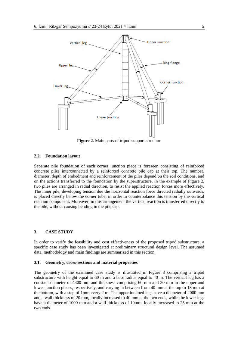
2. PROPOSED TRIPOD CONCEPT 2.1. Main features of proposed tripod concept The proposed wind turbine tower assembly consists of a conventional tubular steel upper structure carrying a horizontal axis wind turbine and an adaptable lower support structure in the form of a tripod and its foundation (Figure 1). The tripod support structure consists of a tubular vertical leg that is coaxial with the upper structure to be supported, and three sets of tubular upper and lower inclined legs, arranged in pairs around the vertical leg. Each inclined leg descends from the vertical leg to the ground level, where each upper and the corresponding lower leg meet at a foundation junction piece that is connected to a set of foundation piles through a pile cap. The foundation level may be the same for all pairs of upper and lower inclined legs, in cases of essentially flat terrains, or it may be different to adapt to the ground level in cases of inclined or rough terrains. The tripod support structure and its constituent parts are illustrated in more detail in Figure 2. It is noted that the number of pairs of upper and lower legs may be different than three, leading to a multi-pod arrangement. This tripod or multi-pod approach substantially enlarges the perimeter of support points of the tower on the ground, thus increasing stability against overturning. Moreover, the support structure resists the large developing overturning moments primarily by axial action, thus exploiting material much better and requiring significantly smaller sections for the legs than the cantilevering upper structure and the tripod’s vertical leg which operate in flexure. The vertical leg is tubular, similar as the upper structure, consisting of individual cans of varying thickness to adjust to the needs imposed by developing mechanical actions, thus requiring gradually smaller thickness from top to bottom. Individual cans are also welded to adjacent cans in the factory in order to form longer, vertical leg sections, having length that depends on transportation constraints. At their ends vertical leg sections are fitted with ring flanges for enabling their connection to other adjacent vertical leg sections, as well as to the upper junction piece at the intersection of vertical leg and upper inclined legs and the lower junction piece at the intersection of vertical leg and lower inclined legs. Vertical leg sections may be lifted onsite by cranes and connected to adjacent parts by prestressed bolts. The vertical leg is fitted with internal equipment, such as ladders, platforms, elevators, cabling and everything else that is needed for the wind turbine operation. It is not structurally necessary to have a foundation below the vertical leg; therefore, its bottom may be a few meters above the ground. This makes it possible to provide a manhole at the bottom of the vertical leg, to enable entrance and exit of personnel and equipment. Thus, the commonly used side opening of tubular towers, requiring a heavy and costly frame stiffener of complex shape, can be avoided. Each upper or lower inclined leg will have a circular hollow steel section that may be fabricated by cold curving flat plates, similarly as the vertical leg, or alternatively employ commercially available tubes for easier procurement. Considering that the mechanical action of inclined legs is primarily axial, with substantial flexural action developing only near the ends, a constant tube thickness over most of their length will be cost effective, with possible thickness increase near the ends. Avoiding the need for gradually varying thickness, combined with relatively small diameter requirements because of the primarily axial function, permits to adopt long tube pieces, thus minimizing the needs for welding and bolting and allowing potentially significant fabrication time and cost reduction. Section lengths are dictated by transportation constraints and individual sections are connected to each other on site by means of ring flanges and prestressed bolts.

6. İzmir Rüzgâr Sempozyumu // 23-24 Eylül 2021 // İzmir 4
Figure 1. Main parts of proposed wind turbine tower assembly Depending on the diameter and the location, ring flanges may be either internal or external, considering accessibility for bolting during erection and for subsequent maintenance. External ring flanges and accompanying bolts may require additional protection against corrosion and environmental factors. In case of internal ring flanges and depending on the inclination of the legs, internal ladders may be necessary to allow access of personnel for bolting and maintenance. In case of external ring flanges bolting and maintenance may be carried out using telescoping boom lifts or scissor lifts.
6. İzmir Rüzgâr Sempozyumu // 23-24 Eylül 2021 // İzmir 5
Figure 2. Main parts of tripod support structure
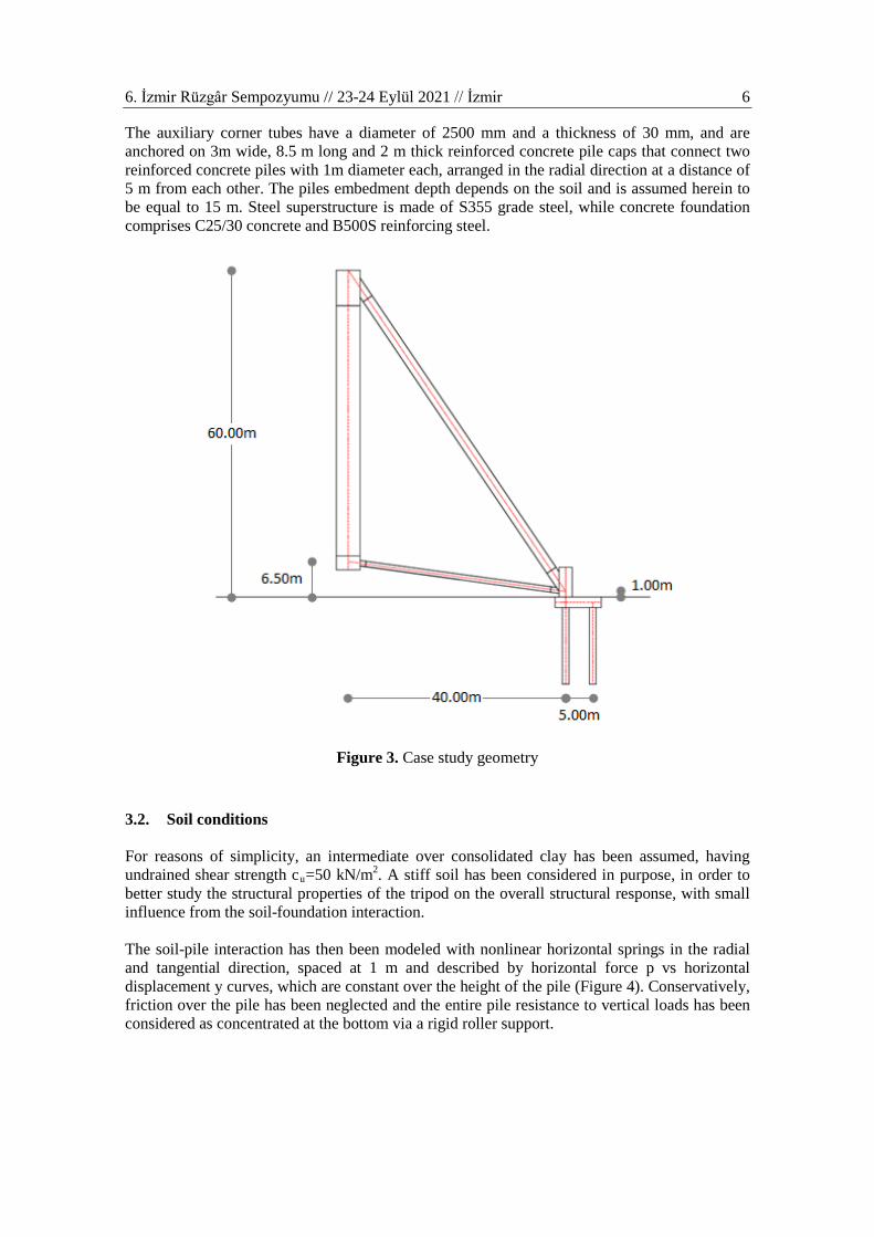
2.2. Foundation layout Separate pile foundation of each corner junction piece is foreseen consisting of reinforced concrete piles interconnected by a reinforced concrete pile cap at their top. The number, diameter, depth of embedment and reinforcement of the piles depend on the soil conditions, and on the actions transferred to the foundation by the superstructure. In the example of Figure 2, two piles are arranged in radial direction, to resist the applied reaction forces more effectively. The inner pile, developing tension due the horizontal reaction force directed radially outwards, is placed directly below the corner tube, in order to counterbalance this tension by the vertical reaction component. Moreover, in this arrangement the vertical reaction is transferred directly to the pile, without causing bending in the pile cap. 3. CASE STUDY In order to verify the feasibility and cost effectiveness of the proposed tripod substructure, a specific case study has been investigated at preliminary structural design level. The assumed data, methodology and main findings are summarized in this section. 3.1. Geometry, cross-sections and material properties The geometry of the examined case study is illustrated in Figure 3 comprising a tripod substructure with height equal to 60 m and a base radius equal to 40 m. The vertical leg has a constant diameter of 4300 mm and thickness comprising 60 mm and 30 mm in the upper and lower junction pieces, respectively, and varying in between from 40 mm at the top to 18 mm at the bottom, with a step of 1mm every 2 m. The upper inclined legs have a diameter of 2000 mm and a wall thickness of 20 mm, locally increased to 40 mm at the two ends, while the lower legs have a diameter of 1000 mm and a wall thickness of 10mm, locally increased to 25 mm at the two ends.
6. İzmir Rüzgâr Sempozyumu // 23-24 Eylül 2021 // İzmir 6
The auxiliary corner tubes have a diameter of 2500 mm and a thickness of 30 mm, and are anchored on 3m wide, 8.5 m long and 2 m thick reinforced concrete pile caps that connect two reinforced concrete piles with 1m diameter each, arranged in the radial direction at a distance of 5 m from each other. The piles embedment depth depends on the soil and is assumed herein to be equal to 15 m. Steel superstructure is made of S355 grade steel, while concrete foundation comprises C25/30 concrete and B500S reinforcing steel.
Figure 3. Case study geometry 3.2. Soil conditions For reasons of simplicity, an intermediate over consolidated clay has been assumed, having undrained shear strength cu=50 kN/m2. A stiff soil has been considered in purpose, in order to better study the structural properties of the tripod on the overall structural response, with small influence from the soil-foundation interaction. The soil-pile interaction has then been modeled with nonlinear horizontal springs in the radial and tangential direction, spaced at 1 m and described by horizontal force p vs horizontal displacement y curves, which are constant over the height of the pile (Figure 4). Conservatively, friction over the pile has been neglected and the entire pile resistance to vertical loads has been considered as concentrated at the bottom via a rigid roller support.

6. İzmir Rüzgâr Sempozyumu // 23-24 Eylül 2021 // İzmir 7
Figure 4. p-y curves representing soil-pile interaction 3.3. Assumed loading Typical values of support reactions of a 120 m tall conventional tubular wind turbine tower with a 5-MW wind turbine installed at its top have been applied on the top of the tripod, comprising a 10000 kN vertical force, a 1500 kN horizontal force, a 150000 kNm bending moment and a 5000 kNm torsional moment. These values have been assumed to represent design loads including partial factors. The vertical load is always directed downwards, while three different scenarios have been considered for the horizontal load, and the bending moment is always considered to act in the same direction as the flexure induced by the horizontal load (Figure 5). The two axes in the horizontal plane are also indicated, in order to relate the directions of forces and moments to the subsequent analysis results. Self-weight of the tripod has also been considered.
Loading scenario 1
Loading scenario 2
Loading scenario 3
Figure 5. Loading scenarios illustrated on the tripod’s plan view
3.4. Structural performance In order to study the overall performance of the tripod structure, a numerical model has been developed in SAP2000, comprising linear beam elements for all members of the steel superstructure and the reinforced concrete foundation, and nonlinear spring elements for the soil springs (Figure 6). The model has been subjected to the loads described in section 3.3, applied on a master node connecting all nodes of the top cross-section of the vertical tripod leg. Linear static analyses have been performed, considered as sufficient at this preliminary design level.
x
y

6. İzmir Rüzgâr Sempozyumu // 23-24 Eylül 2021 // İzmir 8
Figure 6. Numerical model in SAP2000 Deformed shapes obtained for the three load combinations of section 3.3 are illustrated in Figure 7. The maximum observed lateral and vertical displacement at the top of the tripod are 30.8 and 29.8 mm, from loading cases 1 and 3, respectively, while the maximum flexural and torsional rotations are 0.01 rad (=0.56o) and 0.0042 rad (=0.24o), respectively, both from loading case 1. They are partly due to deformation of the superstructure and partly due to deformation of the foundation, taking into account that for the stiff assumed soil conditions the maximum pile cap displacements in the radial direction are equal to 29.5 mm, while in the circumferential direction they are negligible.
Loading scenario 1 Loading scenario 2 Loading scenario 3
Figure 7. Deformed shapes (exaggerated deformation scale)
x y
z

6. İzmir Rüzgâr Sempozyumu // 23-24 Eylül 2021 // İzmir 9
Illustrative axial force and bending moment diagrams of the steel superstructure due to loading scenario 1 are shown in Figure 8. Considering all loading cases, the upper inclined legs have a maximum compressive axial force around 11,000 kN and a maximum resultant bending moment around 9,300 kNm in the main part of the leg, increasing to 12,000 kNm in the thicker end piece. The corresponding quantities for the lower inclined legs are 2.700 kN (tension) and 900 kNm (1250 kNm in the thicker end piece) and for the vertical leg 3.350 kN (tension) and 131,000 kNm bending moment at the top, diminishing to a very small value at the bottom.
Axial forces Bending moments M2 Bending moments M3
Figure 8. Axial force and bending moment diagrams for loading scenario LC1
Design of the steel superstructure according to EN1993-1-1 leads to the utilization ratios shown in Figure 9. This verification assumes elastic section design and takes global leg buckling into account but neglects local shell buckling. For that reason, generous safety margins have been allowed. It is noted however that preliminary finite element analyses employing a dense shell element mesh for the tubular members and considering material and geometric nonlinearity as well as initial imperfections has shown that actually smaller leg thickness would have been sufficient to cover also local buckling verification.
Figure 9. Utilization ratios of steel superstructure considering all loading scenarios

6. İzmir Rüzgâr Sempozyumu // 23-24 Eylül 2021 // İzmir 10
Indicative axial force, shear force and bending moment diagrams of one set of piles are illustrated in Figure 10. It is observed that the outward pile develops a smaller compressive axial force, while placement of the auxiliary corner tube directly above the inward pile, thus directly transmitting to it its vertical reaction component, cancel’s the inward pile’s tension due to the horizontal reaction component, leading to a larger overall compression. This can be further optimized by appropriate placement of the corner tube on the pile cap. It is further observed that, for the considered soil properties, the developing pile shear forces and bending moments diminish smoothly towards the bottom, thus indicating a sufficient pile embedment depth. The maximum calculated shear force is approximately equal to 1400 kN, leading to required shear reinforcement of 40 cm2/m that can be covered by Ø16/10 spiral links, while the worst combination of axial force and bending moment consists of 3750 kN and 3100 kNm, respectively, leading to required longitudinal reinforcement of 240 cm2 (3%), that can be covered by 34 Ø30. These are considered as reasonable reinforcement demands, confirming the adequacy of the considered pile cross-section.
Axial forces Shear forces Bending moments
Figure 10. Axial force, shear force and bending moment diagrams of one set of piles
As a first approach towards evaluating the effect of the tripod’s stiffness to the overall stiffness of the tower assembly, which is important for resonance verification, it has first been attempted to replace the tripod by an equivalent rotational spring at the base of the tubular upper part. To that effect, a concentrated bending moment equal to 100,000 kNm has been applied at the tripod top, and the corresponding rotation has been calculated. This has been repeated for all three directions identified in Figure 5, leading to very similar rotations in all cases, equal to 0.0065 rad. The corresponding rotational spring stiffness is then computed equal to approximately 15,300 MNm/rad. Referring to [3], where the influence of a base rotational spring on the fundamental vibration frequency of a tubular wind turbine tower similar to the one assumed as upper part in this case study has been investigated, it is estimated that the tripod and its foundation will cause a reduction in the order of 15% to the fundamental vibration frequency that the tubular superstructure would have if it were fixed at its base. In order to isolate the effect of the foundation, the same process has been repeated for the case of rigidly fixed tripod, leading to a rotation of 0.0064 rad at the top of the tripod, as well as a rigidly hinged tripod, leading to a rotation of 0.0066 rad, thus identifying a negligible influence of the foundation stiffness for the considered soil type. Subsequently, a typical 120 m tall tubular superstructure, comprising a fundamental frequency ω1=1.10 rad/sec if fixed at its base,

6. İzmir Rüzgâr Sempozyumu // 23-24 Eylül 2021 // İzmir 11
has been modelled on top of the tripod. Assuming a rigidly hinged tripod, the reduced frequency of the overall assembly is found equal to 0.92 rad/sec, corresponding to a 16% reduction, not far from the rotational spring approximation. Having a specific hub height target for the wind turbine, desirable frequency values can thus be achieved by appropriately adjusting the tripod height and radius, which are the two main parameters controlling the tripod stiffness.
Typical 120m tall tubular (ω1=1.10 rad/sec) Overall 180m tall tower assembly (ω1=0.92 rad/sec)
Figure 11. Fundamental vibration periods and corresponding frequencies
3.5. Weight and cost considerations For the dimensions and cross-sections described above, the estimated weight of the tripod parts consists of 210 t for the three upper legs, 35 t for the three lower legs, 200 t for the vertical leg and 35 t for the three corner tubes, adding up to 480 t, which includes approximate weights of the necessary ring flanges. Considering an approximate weight of 320 t for the conventional tubular upper part, a safe estimate of the total steel weight for the 180 m tower assembly would be around 800 t. It is noted that the smaller diameter tubes of upper, lower and corner legs could be fabricated by other methods than cold curving, such as spiral welding, resulting in significant savings in unit price. Regarding the foundation, assuming a relatively stiff soil, a total of six piles of 1 m diameter and an embedment length in the order of 20 m and an estimated concrete volume of 160 m3 for the pile caps, would lead to a foundation cost of approximately 50,000€, much less than for the matt foundation of a conventional tubular tower. The combined superstructure and foundation cost for a tower with 180 m hub height is expected to be in the range of 15%-40% less than the corresponding tubular steel, concrete and hybrid solutions, notwithstanding the fact that this height would be unrealistic for a conventional tubular steel tower with ring flange connections. These findings justify considerable optimism that the proposed concept may offer a competitive solution for achieving taller hub heights for onshore wind turbines of high rated power.

6. İzmir Rüzgâr Sempozyumu // 23-24 Eylül 2021 // İzmir 12
4. SUMMARY AND CONCLUSIONS A tripod substructure has been proposed as a realistic, modular and scalable solution for wind turbine towers of very large heights, having suitable member sections and joint details that satisfy all necessary verification criteria related to safety and operation, while at the same time respecting fabrication, onshore and offshore transportation, erection, maintenance and dismantling constraints. Thanks to its scalability, the concept can also be used for repowering existing wind farms without replacing the towers and turbines, but by simply elevating them to exploit the improved wind conditions at taller heights and thus to increase power production. Moreover, existing tubular towers have, in most cases, a heavy reinforced concrete matt foundation in order to counterbalance the large imposed bending moments. On the contrary, the tripod support structure utilizes a lighter and more cost-effective foundation solution, based on reinforced concrete piles below each tripod leg. A preliminary structural investigation has indicated the feasibility of the concept and provided indicative section requirements. A rough cost estimation based on these sections has illustrated the competitiveness of the proposed solution compared to other tower types for large hub heights. REFERENCES [1] European Commission, (2020), European Green Deal: 2030 Climate & Energy
Framework, https://ec.europa.eu/clima/policies/strategies/2030_en#tab-0-0 (accessed 26 June 2021).
[2] Veljkovic, M., Feldmann, M., Naumes, J., Pak, D., da Silva, L.S., Rebelo, C., (2011), Wind Turbine Tower Design, Erection and Maintenance, Editor(s): John D. Sørensen, Jens N. Sørensen, In Woodhead Publishing Series in Energy, Wind Energy Systems, Woodhead Publishing, p. 274-300.
[3] Koulatsou, K.G., Kazakis, G., Gantes, C.J., Lagaros, N.D., (2020), Resonance Investigation and its Effects on Weight Optimization of Tubular Steel Wind Turbine Towers, Procedia Manufacturing, Vol. 44, p. 4-11.
[4] European Committee of Standardization, (2007), EN1993-1-6:2007, Eurocode 3: Design of Steel Structures – Part 1.6: Strength and Stability of Shell Structures.
[5] European Committee of Standardization, (2015), EN1993-1-6:2007/A1:2015, Eurocode 3: Design of Steel Structures – Part 1.6: Strength and Stability of Shell Structures – Corrigendum.
[6] European Committee of Standardization, (2005), EN1993-1-9:2005, Eurocode 3: Design of Steel Structures – Part 1.9: Fatigue.
[7] International Electrotechnical Commission, (2005), IEC61400-1:2005, Wind Turbines – Part 1: Design Requirements, 3rd edition.
[8] Germanischer Lloyd, (2010), Guideline for the Certification of Wind Turbines. [9] Det Norske Veritas (DNV), (2002), Guidelines for Design of Wind Turbines, Wind
Energy Department, Risø National Laboratory. [10] Wang, X., Zeng, X., Li, J., Yang, X., & Wang, H., (2018), A Review on Recent
Advancements of Substructures for Offshore Wind Turbines, Energy Conversion and Management, Vol. 158, p. 103-119.
[11] Hu, Y., Yang, J., Baniotopoulos, C., Wang, X., & Deng, X., (2020), Dynamic Analysis of Offshore Steel Wind Turbine Towers Subjected to Wind, Wave and Current Loading during Construction, Ocean Engineering, Vol. 216, 108084.
[12] Jiang, Z., (2021), Installation of Offshore Wind Turbines: A Technical Review, Renewable and Sustainable Energy Reviews, Vol. 139, 110576.

6. İzmir Rüzgâr Sempozyumu // 23-24 Eylül 2021 // İzmir 13
[13] Yeter, B., Garbatov, Y., & Soares, C. G., (2015), Fatigue Damage Assessment of Fixed Offshore Wind Turbine Tripod Support Structures, Engineering Structures, Vol. 101, p. 518-528.
[14] Hao, E., & Liu, C., (2017), Evaluation and Comparison of Anti-impact Performance to Offshore Wind Turbine Foundations: Monopile, Tripod, and Jacket, Ocean Engineering, Vol. 130, p. 218-227.
[15] Ma, H., Yang, J., & Chen, L., (2018), Effect of Scour on the Structural Response of an Offshore Wind Turbine Supported on Tripod Foundation, Applied Ocean Research, Vol. 73, p. 179-189.
[16] Arcigni, F., Abhinav, K. A., Collu, M., & Venturini, M., (2021), Analysis of Tripod Supported Offshore Wind Turbines under Conditions of Marine Growth, Ocean Engineering, Vol. 220, 108441.
[17] Wind-turbine-models.com - The Big Portal for Wind Energy, (2021), Multibrid M5000, https://en.wind-turbine-models.com/turbines/22-multibrid-m5000 (accessed 26 June 2021).
[18] Canadian Patent Application CA 2 759 979 A1, (2012), Wind Turbine Tower Assembly and Method for Assembling the Same.
[19] European Patent Application EP 2 444 663 A2, (2012), Onshore Wind Turbine with Tower Support System.
[20] International Patent Application WO 2011/147477 A1, 2011, A Support Structure for a Wind Turbine.
[21] PCT Application No. PCT/TR2020/051117, A Multi-Pod Support Structure for a Wind Turbine Tower, Unpublished.