Embed Size (px)
Citation preview

Research ArticleA Thin and Broadband Linear-to-Circular Polarizer Based onGrid-Patch Structure for Ku-Band
Hao-ming Hu , Dong-fang Zhou, Xue Lei, and Jun-mo Wu
National Digital Switching System Engineering and Technological R&D Center, Zhengzhou 450002, China
Correspondence should be addressed to Hao-ming Hu; [email protected]
Received 13 September 2018; Revised 8 November 2018; Accepted 12 November 2018; Published 13 December 2018
Academic Editor: Francisco Falcone
Copyright © 2018 Hao-ming Hu et al. This is an open access article distributed under the Creative Commons AttributionLicense, which permits unrestricted use, distribution, and reproduction in any medium, provided the original work isproperly cited.
A three-layer circular polarization selective surface operating in Ku-band is proposed in this communication. We design a thingrid-patch structure to achieve linear-to-circular polarization transformation over a wide frequency band. The periodic structurecould be analyzed via equivalent circuit model theory. Numerical simulations have been carried out and the prototype structureshave been fabricated and experimentally validated. The axial ratio (AR) of the transmitted field remained below 3 dB over theentire bandwidth, and the 3 dB AR bandwidth is approximately 44.6%. The design has a subwavelength thickness of 6mm(0.28λc). Besides, this design could be also applied to beam scanning antennas because of its capability in condition of largeoblique incidence angle (±50 deg).
1. Introduction
In recent years, with the rapid development of communica-tion technologies, the range of antenna applications hasbecome wider and the demand for communication underdifferent propagation environment has become higher. Thus,single polarization mode of electromagnetic waves can nolonger meet the requirements.
Nowadays, linear-to-circular polarization converterbased on frequency selective surface (FSS) has been stud-ied extensively and how to achieve large angle of incidenceis significant in beam scanning antenna. Most often, polar-ization control is achieved with a quarter-wave plate whichis one or several layers and the common structure ismeander line [1]. In [2], Fei et al. proposed a novelsingle-layer linear-to-circular polarizer consisting of hybridmeander line and loop configuration. Although it is char-acterized by wide band, its insertion loss exceeds 3 dB.Also, other single-layer structures such as cross slot [3]and split slot ring [3] are difficult to achieve broadbandand low loss at the same time. To solve this problem, mul-tilayer CPFSS structures become a hot research point [4].
Momeni Hasan Abadi and Behdad proposed the conceptof a miniaturized-element frequency selective surface(MEFSS) [5] that provides a stable frequency responsefor 40% 3dB AR bandwidth and oblique incidence anglesduring ±45 degrees (low insertion loss). An approachfocusing on designing multilayer polarizer was presentedby Blanco and Sauleau in [6]. His design (five metasurfacelayers) could achieve wide axial ratio bandwidth of 19.6%for 50 degrees of incidence. Up to now, the maximumdegree of incidence is 70 [7] which uses five layers. Butits bandwidth is narrow, only 4.8% in 8–8.4GHz. How-ever, the overall thickness of these designs is electricallylarge. Thus, two [8, 9] or three layers [10, 11] play a muchmore important role in linear-to-circular polarizer design-ing and three-layer structure is considered as the mini-mum number of layers that is possible to provide perfecttransmission and complete phase coverage. Increasing orreducing the number of layers could not meet the demandof performance and cost.
Considering three is the most appropriate number oflayers, in this paper, a three-layer linear-to-circular polar-izer is proposed and the structure of grid-patch is efficient
HindawiInternational Journal of Antennas and PropagationVolume 2018, Article ID 5695987, 8 pageshttps://doi.org/10.1155/2018/5695987
in polarization transformation. It is characterized by widebandwidth (44.6%) and low profile (0.28λc). Moreover, itis suitable to be applied to beam scanning antenna (±50degrees of incidence) [12].
The rest of this communication is organized asfollows. Section 2 describes the configuration and designprinciple of the proposed linear-to-circular polarizer. InSection 3, simulated and measured results of the designed
polarizer are presented. Finally, a brief summary is givenin Section 4.
2. Description of the Proposed Structure
2.1. Geometry. Design and operating principle will beanalyzed in this section. It should be noted that a neces-sary condition for achieving high transmission efficiency is
�휆/8
�휆/8
xy
z
(a)
Dielectricsubstrates
Inductivegrids
Capacitivepatches
Foam
�휆/8
z
y
x
(b)
W1
H1
W2H2
H3
Dx
Dy
W3
H4
x
y
(c)
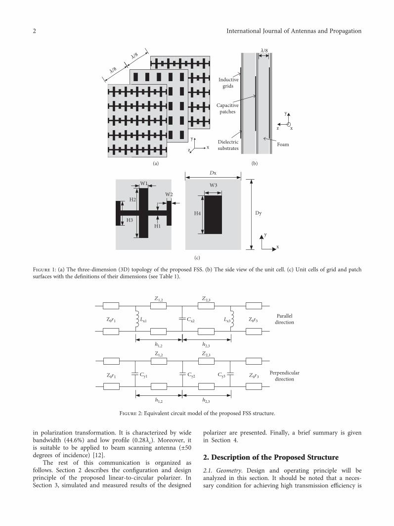
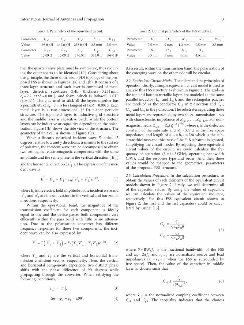
Figure 1: (a) The three-dimension (3D) topology of the proposed FSS. (b) The side view of the unit cell. (c) Unit cells of grid and patchsurfaces with the definitions of their dimensions (see Table 1).
h1,2 h2,3
Z0r1
Z0r1
Z0r3
Z0r3
Z1,2 Z2,3
Z1,2 Z2,3
Lx1 Lx3Cx2
Cy1 Cy2 Cy3
Paralleldirection
Perpendiculardirection
h1,2 h2,3
Figure 2: Equivalent circuit model of the proposed FSS structure.
2 International Journal of Antennas and Propagation
that the quarter-wave plate must be symmetric, thus requir-ing the outer sheets to be identical [10]. Considering aboutthis principle, the three-dimension (3D) topology of the pro-posed FSS is shown in Figures 1(a) and 1(b). It consists of athree-layer structure and each layer is composed of metallayer, dielectric substrates (F4B, thickness = 0.254mm,εr = 2.2, tanδ=0.001), and foam, which is Rohacell 71HF(εr = 1.1). The glue used to stick all the layers together hasa permittivity of εr = 3.5, a loss tangent of tanδ=0.0015. Eachmetal layer is a two-dimensional (2-D) planar periodicstructure. The top metal layer is inductive grid structureand the middle layer is capacitive patch, while the bottomlayers can be inductive or capacitive depending on the polar-ization. Figure 1(b) shows the side view of the structure. Thegeometry of unit cell is shown in Figure 1(c).
When a linearly polarized incident wave Ei, titled 45degrees relative to x and y directions, transmits to the surfaceof polarizer, the incident wave can be decomposed to obtaintwo orthogonal electromagnetic components with the same
amplitude and the same phase in the vertical direction E ⊥
and the horizontal direction E ∥ . The expression of the inci-dent wave is
Ei= E ⊥ + E ∥ = E0 e ⊥ + e ∥ e−jkz, 1
whereE0 is the electricfield amplitudeof the incidentwave ande ⊥ and e ∥ are the unit vectors in the vertical and horizontaldirections, respectively.
Within the operational band, the magnitude of thetransmission coefficient for each component is ideallyequal to one and the device passes both components veryefficiently within the pass band with little or no attenua-tion. Due to the polarization converter has differentfrequency responses for these two components, the inci-dent wave can be also expressed by:
Ei= T E ⊥ + E ∥ = E0 T⊥ e ⊥ + T∥ e ∥ e−jkz , 2
where T⊥ and T∥ are the vertical and horizontal trans-mission coefficient vectors, respectively. Then, the verticaland horizontal components experience two distinct phaseshifts with the phase difference of 90 degrees whilepropagating through the converter. When satisfying thefollowing conditions,
T⊥ = T∥ , 3
Δφ = φ⊥ − φ∥ = ±90° 4
As a result, within the transmission band, the polarization ofthe emerging wave on the other side will be circular.
2.2. Equivalent Circuit Model. To understand the principles ofoperation clearly, a simple equivalent circuit model is used toanalyze this FSS structure as shown in Figure 2. The grids inthe top and bottom metallic layers are modeled as the sameparallel inductor (Lx1 and Lx3), and the rectangular patchesare modeled as the conductor Cx2 in x direction and Cy1,Cy2, andCy3 in the y direction. The substrates separating thesemetal layers are represented by two short transmission lineswith characteristic impedance of Zi,i+1,… , ZN−1,N . For non-
magneticmedia,Zi,i+1 = Z0 εi,i+1r−1/2, where εr is the dielectric
constant of the substrate and Z0 = 377Ω is the free spaceimpedance, and length of h1,2 = h2,3 = λ/8 which is the sub-strate thickness and thickness of the F4B substrate is ignored,simplifying the circuit model. By adjusting these equivalentcircuit values of the circuit, we could calculate the fre-quency of operation (f0 = 14.5GHz), operating bandwidth(BW), and the response type and order. And then thesevalues would be mapped to the geometrical parametersof the proposed FSS structure.
2.3. Calculation Procedure. In the calculation procedure, toobtain the values of each elements of the equivalent circuitmodels shown in Figure 2. Firstly, we will determine allof the capacitor values. By using the values of capacitor,we can calculate the values of the equivalent inductor,respectively. For this FSS equivalent circuit shown inFigure 2, the first and the last capacitors could be calcu-lated by using [13].
Cy1 =q1
r1ω0Z0δ,
Cy3 =q3
r3ω0Z0δ,
5
where δ = BW/f0 is the fractional bandwidth of the FSSand ω0 = 2πf0 and r1, r3 are normalized source and loadimpedances (r1 = r3 = 1 when the FSS is surrounded byfree space). Then, the value of the capacitor in middlelayer is chosen such that
Cy2 ≤Cy1
δk1,22 , 6
where k1,2 is the normalized coupling coefficient betweenCy1 and Cy3. The inequality indicates that the choices
Table 1: Parameters of the equivalent circuit.
Parameter L x1 C x2 L x3 h 1,2 h 2,3
Value 198.0 pH 342.0 pH 235.0 pH 2.5mm 2.5mm
Parameter Z 1,2 Z 2,3 C y1 C y2 C y3
Value 13.09Ω 13.09Ω 176.0 fF 383.0 fF 169.0 fF
Table 2: Optimal parameters of the FSS structure.
Parameter D x D y W 1 W 2 W 3
Value 7.5mm 9mm 1.2mm 0.5mm 2.3mm
Parameter H 1 H 2 H 3 H 4
Value 0.5mm 5mm 4mm 4.6mm
3International Journal of Antennas and Propagation

for the value of Cy2 are not unique as long as it meetsthis condition.
After calculating the values of all the capacitors, the phasedelay in y direction could be determined. According to thephase delay, to achieve 90 degrees phase difference betweenx and y direction, we should adjust the values of parametersin x direction to provide phase compensation. Thus, theinductors Lx1 and Lx3 can be determined as follows:
Lx1 =1
ω2 Cy1 − k1,2δ Cy1Cy2,
Lx3 =1
ω2 Cy3 − k2,3δ Cy2Cy3
7
To simplify the calculation process, we let Cx2 meet thesame condition (6). Up to now, all of the values of mainparameters in equivalent circuit are determined as shown inTable 1. Based on the results, the values of structural param-eters can be obtained as shown in Table 2.
According to these calculation results of structure param-eters, simulation and optimization of the proposed structurehave been carried out. Finally, a prototype of structure isfabricated and measured. We would prove the accuracy ofour calculations in the next section.
3. Results and Analysis
3.1. Simulation Results. The simulation of the proposed FSSwas carried out by using the commercial full-wave EM solver(CST Microwave Studio), and the results have been com-puted at normal incidence firstly. Figure 3(a) shows the sim-ulated phase and phase difference between Eout
∥ and Eout⊥ . It
can be seen that the phase difference (solid line) betweenEout∥ and Eout
⊥ is approximately 90 degrees, matching the con-dition (4). With regard to Figure 3(b), which shows thereturn loss and insertion loss of the reflection and transmis-sion with normally incident LP wave, the polarizers providea comparable magnitude of Eout
∥ and Eout⊥ , which matches
the condition (3).After analyzing the two conditions, the axial ratio (AR)
could be calculated by [14].
AR = E2∥ cos2τ + E∥E⊥ sin 2τ cos δ + E2
⊥ sin2τE2∥ sin2τ − E∥E⊥ sin 2τ cos δ + E2
⊥ cos2τ, 8
where δ is the phase difference between Eout∥ and Eout
⊥ and τ isexpressed by
τ = 12 tan−1 2E∥E⊥
E2∥ − E2
⊥9
Based on the results, the axial ratio of transmitted circu-larly polarized output wave is shown in Figure 3(c). For an
axial ratio of less than 3dB, the bandwidth is from 11.36 to17.83GHz, approximately 44.6% 3dB AR bandwidth cover-ing most of Ku-band. Within the whole AR< 3 dB band-width, the transmission coefficient is less than 1.5 dBbetween the 3 dB AR bandwidth.
During the optimization, the operating frequencycould be changed via adjusting parameters of the middlepatch, as shown in Figure 4(a). Generally, the size ofpatch has an effect on the value of equivalent conductorCx1 and Cy2. Therefore, the phase and magnituderesponses for both perpendicular and parallel polarizationsare changed, leading to the change of frequency response.The two responses can be calculated using the followingformula [5]:
Δf t ≥Δf opt
1 − Δϕd/Δϕt, 10
where Δf t and Δϕt are their frequency and phase shifts,Δf opt is the operating bandwidth, and Δϕd is the desiredphase difference of 90° in an ideal situation.
Figure 4(b) shows the influence of parameters of top andbottom grid structure on bandwidth. H2 and H3 mainly con-trol the length of vertical strips which couple capacitively.Therefore, they affect the value of conductor Cy1 and Cy3.When increasing the length of grid strips, the bandwidthbecomes narrow due to the influence on the loss of parallel-direction electric field only, which results in unequal ampli-tudes in parallel and perpendicular directions. Consequently,the axial ratio deteriorates.
On the other hand, although the bandwidth (H2=4.8mmand H3=3.6mm) is wider than the bandwidth (H2=5.1mmand H3=3.9mm) in the condition of normal incidence, wechoose the parameters of H2=5.1mm and H3=3.9mmconsidering different oblique incidence. Here are thesimulated and experimental axial ratio results for obliqueincidences in Figure 5.
3.2. Analysis on Oblique Incidence and Experimental Results.It can be seen from Figures 5(a) and 5(b) that with theincreasing of oblique incidence, the 3 dB AR bandwidthbecomes narrow which is a common trend. Leading tothe deterioration of axial ratio is that in condition of largeoblique incidence, the transmitted wave hardly meets theconditions (3) and (4). However, the proposed polarizationconverter still shows a good performance in case of 50degrees oblique incidence in both x-z and y-z planes.Therefore, the maximum of oblique incidence angle is 50degrees.
The experimental results are shown in Figures 5(c) and5(d). The measurement procedure and photograph of thefabricated polarizer converter are shown in Figure 6. Themeasured frequency is set from 11GHz to 19GHz. Due tothe limited operating bandwidth of the standard-gain hornused (Ku-band horn, operating in 12–18GHz), it wouldcause the deterioration in low and high frequency. Fromthe results, we can see that there is a good consistency
4 International Journal of Antennas and Propagation

between the experimental and simulated results, despite theinstability in axial ratio and the shift in frequency. Thesedeviations may be caused by the manufacturing errors andthe experimental environment.
The simulated and measured transmission and reflectioncoefficient results are shown in Figure 7 which demonstratethat during the whole 3 dB AR bandwidth, the peak loss isless than 1.5 dB.
16−360
−315
−270
−225
−180
−135
−90
−45
0
Phas
e (de
gree
s)
Frequency (GHz)Phase of perpendicular componentPhase of parallel componentPhase difference
1810 11 12 13 14 15 17
(a)
−40
−30
−20
−10
0
Reflected perpendicular componentReflected parallelcomponent
Transmitted perpendicularcomponent
Transmitted parallelcomponent
Refle
ctio
n co
effici
ent (
dB)
−5
−4
−3
−2
−1
0
Tran
smiss
ion
coeffi
cien
t (dB
)
16Frequency (GHz)
1810 11 12 13 14 15 17
(b)
0
1
2
3
4
Axi
al ra
tio (d
B)
16Frequency (GHz)
18 19 2010 11 12 13 14 15 17
(c)
Figure 3: The simulation results of the proposed FSS structure. (a) The phase relation between output wave in perpendicular and paralleldirection. (b) The transmission and reflection coefficients. (c) The axial ratio of proposed FSS under normal incidence.
100
1
2
3
4
5
6
7
8
Axi
al ra
tio (d
B)
Frequency (GHz)W3 = 2 H4 = 4.1W3 = 2.3 H4 = 4.3W3 = 2.6 H4 = 4.5
2018161412
(a)
H3 = 3.6 H2 = 4.8H3 = 3.9 H2 = 5.1H3 = 4.2 H2 = 5.4
100
1
2
3
4
5
6
7
8
Axi
al ra
tio (d
B)
Frequency (GHz)2018161412
(b)
Figure 4: Simulated axial ratio of the proposed FSS for different (a) parameters of middle patch structure and (b) parameters of top andbottom grid structure.
5International Journal of Antennas and Propagation

The comparison between our design and some typicalpublished polarizers is shown in Table 3 and these data arebased on simulation due to some designs are not fabricated
and measured. Contrast with single- and multilayer-layerdesign, the polarizer we proposed has advantages in band-width and peak loss.
120
1
2
3
4
5
6
7
8
Axi
al ra
tio (d
B)
Frequency (GHz)0 deg phi = 015 deg phi = 0
35 deg phi = 050 deg phi = 0
11 19181716151413
(a)
12Frequency (GHz)
0 deg phi = 9015 deg phi = 90
35 deg phi = 9050 deg phi = 90
11 191817161514130
1
2
3
4
5
6
7
8
Axi
al ra
tio (d
B)
(b)
0
1
2
3
4
5
6
7
8
Axi
al ra
tio (d
B)
12Frequency (GHz)
0 deg phi = 015 deg phi = 0
35 deg phi = 050 deg phi = 0
11 181716151413
(c)
0
1
2
3
4
5
6
7
8
Axi
al ra
tio (d
B)
12Frequency (GHz)
0 deg phi = 9015 deg phi = 90
35 deg phi = 9050 deg phi = 90
11 181716151413
(d)
Figure 5: Simulated (a, b) and experimental (c, d) axial ratio results for oblique incidences of 0, 15, 35, and 50 degrees in (a) x-z and (b) y-zplanes.
Transmitter Receiver
Side view
Top view
6 mm
x
yz
Figure 6: The measurement procedure and two views (top and side views) of the fabricated polarization converter.
6 International Journal of Antennas and Propagation

4. Conclusion
In this communication, we present a three-layer linear-to-circular polarizer based on grid-patch structure for Ku-band. The equivalent circuit model theory is used to analyzethe operating principle of this periodic structure and thedesign process is given. Simulation, optimization, and mea-surement have been carried out. The proposed structureshows a good performance on thickness (0.28λc) and band-width (44.6%). Besides, this design could be also applied tobeam scanning antennas because of its capability in condi-tion of large oblique incidence angle (±50 deg).
11 12 13 14 15 16 17 18 19−40
−35
−30
−25
−20
−15
−10
−5
0Re
flect
ion
coeffi
cien
t (dB
)
Tran
smiss
ion
coeffi
cien
t (dB
)
Frequency (GHz)S11 for 0 degS11 for 15 degS11 for 35 degS11 for 50 deg
S21 for 0 degS21 for 15 degS21 for 35 degS21 for 50 deg
−8
−7
−6
−5
−4
−3
−2
−1
0
(a)
Refle
ctio
n co
effici
ent (
dB)
11 12 13 14 15 16 17 18 19Frequency (GHz)
S11 for 0 degS11 for 15 degS11 for 35 degS11 for 50 deg
S21 for 0 degS21 for 15 degS21 for 35 degS21 for 50 deg
Tran
smiss
ion
coeffi
cien
t (dB
)
−8
−7
−6
−5
−4
−3
−2
−1
0
−55
−50
−45
−40
−35
−30
−25
−20
−15
−10
−5
0
(b)
11 12 13 14 15 16 17 18−40
−35
−30
−25
−20
−15
−10
−5
0
Refle
ctio
n co
effici
ent (
dB)
Tran
smiss
ion
coeffi
cien
t (dB
)
Frequency (GHz)S11 for 0 degS11 for 15 degS11 for 35 degS11 for 50 deg
S21 for 0 degS21 for 15 degS21 for 35 degS21 for 50 deg
−8
−7
−6
−5
−4
−3
−2
−1
0
(c)
11 12 13 14 15 16 17 18Frequency (GHz)
S11 for 0 degS11 for 15 degS11 for 35 degS11 for 50 deg
S21 for 0 degS21 for 15 degS21 for 35 degS21 for 50 deg
Refle
ctio
n co
effici
ent (
dB)
Tran
smiss
ion
coeffi
cien
t (dB
)
−6
−5
−4
−3
−2
−1
0
−55
−50
−45
−40
−35
−30
−25
−20
−15
−10
−5
0
(d)
Figure 7: Simulated (a, b) and experimental (c, d) transmission and reflection coefficient results for oblique incidences of 0, 15, 35, and 50degrees in (a, c) x-z and (b, d) y-z planes.
Table 3: Comparisons between the proposed structure and someother reported linear-to-circular polarizer.
Ref. work Layer Bandwidth Oblique performance
[3] 1 21% N/A
[10] 3 (0.31λc) 40.5% ±45[11] 3 (0.33λc) >35% ±45[5] 5 40% ±45[6] 5 19.6% ±50[7] 5 4.8% ±70Our work 3 (0.28λc) 44.6% ±50
7International Journal of Antennas and Propagation

Data Availability
The data used to support the findings of this study areavailable from the corresponding author upon request.
Conflicts of Interest
There is no conflict of interest regarding the publication ofthis paper.
References
[1] J.-M. Wu, X. Lei, D.-f. Zhou, L. Hou, and H.-w. Chen, “Designof ring-focus elliptical beam reflector antenna,” InternationalJournal of Antennas and Propagation, vol. 2016, Article ID9615064, 7 pages, 2016.
[2] P. Fei, Z. Shen, X. Wen, and F. Nian, “A single-layer circularpolarizer based on hybrid meander line and loop configura-tion,” IEEE Transactions on Antennas and Propagation,vol. 63, no. 10, pp. 4609–4614, 2015.
[3] M. Euler, V. Fusco, R. Dickie, R. Cahill, and J. Verheggen,“Sub-mm wet etched linear to circular polarization FSS basedpolarization converters,” IEEE Transactions on Antennas andPropagation, vol. 59, no. 8, pp. 3103–3106, 2011.
[4] J.-m. Wu, D.-f. Zhou, X. Lei, J. Gao, and H.-m. Hu, “Design ofa compact broadband 90° waveguide twist based on double-corner-cut square slots,” International Journal of Antennasand Propagation, vol. 2017, Article ID 8657620, 5 pages, 2017.
[5] S. M. A. Momeni Hasan Abadi and N. Behdad, “Widebandlinear-to-circular polarization converters based onminiaturized-element frequency selective surfaces,” IEEETransactions on Antennas and Propagation, vol. 64, no. 2,pp. 525–534, 2016.
[6] D. Blanco and R. Sauleau, “Broadband and broad-angle multi-layer polarizer based on hybrid optimization algorithm forlow-cost Ka-band applications,” IEEE Transactions on Anten-nas and Propagation, vol. 66, no. 4, pp. 1874–1881, 2018.
[7] T. Dousset, A. Bellion, I. Le Roy, and G. Morvan, “Polariseurscirculaires’a m’eandres pour applications spatiales,” in 18’emesJourn’ees Nationales Microondes, pp. 15–17, Paris, France,2013.
[8] E. Arnaud, R. Chantalat, M. Koubeissi, T. Monediere,E. Rodes, and M. Thevenot, “Global design of an EBG antennaand meander-line polarizer for circular polarization,” IEEEAntennas and Wireless Propagation Letters, vol. 9, pp. 215–218, 2010.
[9] L. Sun and A. Zaghoul, “Two-layer wide-band meander-line-polarizer,” US Patent http://www.google.ch/patents/US20050104791, 2005.
[10] C. Pfeiffer and A. Grbic, “Millimeter-wave transmitarrays forwavefront and polarization control,” IEEE Transactions onMicrowave Theory and Techniques, vol. 61, no. 12, pp. 4407–4417, 2013.
[11] M.-A. Joyal and J.-J. Laurin, “Analysis and design of thin circu-lar polarizers based on meander lines,” IEEE Transactions onAntennas and Propagation, vol. 60, no. 6, pp. 3007–3011, 2012.
[12] J. Gao, X. Lei, G.-H. Chen, Y. Zhang, and J.-M. Wu, “Design ofthe variable inclination continuous transverse stub antennabased on rectangular grating slow-wave structure,” Interna-tional Journal of Antennas and Propagation, vol. 2018, ArticleID 5793535, 7 pages, 2018.
[13] N. Behdad and M. A. al-Joumayly, “A generalized synthesisprocedure for low-profile frequency selective surfaces withodd-order band-pass responses,” IEEE Transactions on Anten-nas and Propagation, vol. 58, no. 7, pp. 2460–2464, 2010.
[14] N. Li and Y. Feng, “Fast measuring axial ratio of circular polar-ization antennas based on linear polarization antenna,” Infra-red and Laser Engineering, vol. 42, no. 8, pp. 2216–2220, 2013.
8 International Journal of Antennas and Propagation

International Journal of
AerospaceEngineeringHindawiwww.hindawi.com Volume 2018
RoboticsJournal of
Hindawiwww.hindawi.com Volume 2018
Hindawiwww.hindawi.com Volume 2018
Active and Passive Electronic Components
VLSI Design
Hindawiwww.hindawi.com Volume 2018
Hindawiwww.hindawi.com Volume 2018
Shock and Vibration
Hindawiwww.hindawi.com Volume 2018
Civil EngineeringAdvances in
Acoustics and VibrationAdvances in
Hindawiwww.hindawi.com Volume 2018
Hindawiwww.hindawi.com Volume 2018
Electrical and Computer Engineering
Journal of
Advances inOptoElectronics
Hindawiwww.hindawi.com
Volume 2018
Hindawi Publishing Corporation http://www.hindawi.com Volume 2013Hindawiwww.hindawi.com
The Scientific World Journal
Volume 2018
Control Scienceand Engineering
Journal of
Hindawiwww.hindawi.com Volume 2018
Hindawiwww.hindawi.com
Journal ofEngineeringVolume 2018
SensorsJournal of
Hindawiwww.hindawi.com Volume 2018
International Journal of
RotatingMachinery
Hindawiwww.hindawi.com Volume 2018
Modelling &Simulationin EngineeringHindawiwww.hindawi.com Volume 2018
Hindawiwww.hindawi.com Volume 2018
Chemical EngineeringInternational Journal of Antennas and
Propagation
International Journal of
Hindawiwww.hindawi.com Volume 2018
Hindawiwww.hindawi.com Volume 2018
Navigation and Observation
International Journal of
Hindawi
www.hindawi.com Volume 2018
Advances in
Multimedia
Submit your manuscripts atwww.hindawi.com