Embed Size (px)
Citation preview

University of Nebraska - LincolnDigitalCommons@University of Nebraska - LincolnOpen-Access* Master's Theses from the Universityof Nebraska-Lincoln Libraries at University of Nebraska-Lincoln
9-1977
A Synthesis of Modern Rail TransportationEngineering PracticesDonald D. CookUniversity of Nebraska-Lincoln
Follow this and additional works at: http://digitalcommons.unl.edu/opentheses
Part of the Civil Engineering Commons
This Thesis is brought to you for free and open access by the Libraries at University of Nebraska-Lincoln at DigitalCommons@University of Nebraska -Lincoln. It has been accepted for inclusion in Open-Access* Master's Theses from the University of Nebraska-Lincoln by an authorized administrator ofDigitalCommons@University of Nebraska - Lincoln.
Cook, Donald D., "A Synthesis of Modern Rail Transportation Engineering Practices" (1977). Open-Access* Master's Theses from theUniversity of Nebraska-Lincoln. 37.http://digitalcommons.unl.edu/opentheses/37

A SYNTHESIS OF MODERN RAIL TRANSPORTATION
ENGINEERING PRACTICES
by
Donald D. Cook
A THESIS
Presented to the Faculty of
The Graduate College in the University of Nebraska
In Partial Fulfillment of Requirements
For the Degree of Master of Science
Department of Civil Engineering
Under the Supervision of
Dr. Edward R. Post Dr. Patrick J. McCoy Dr. Edward N. Wilson
Lincoln, Nebraska
September, 1977

ACKNOWLEDGEMENTS
I wish to thank Dr. E. R. Post, Dr. P. T. M~Coy, and
Dr. E. N. Wilson, my thesis advisory corrmittee for their assistance.
Thanks are also due Sharon Nichols and Kim Seip whose typing
skills saved me a great amount of anguish and Gary Steffans who
assisted with the chapter on signaling.
Finally, appreciation is given my wife Kathy for her moral
support and patience and to ITlY children Amy and Becky for their
consideration.
ii

TABLE OF CONTENTS
TITLE •••••••• . . . . . . . . . . . . ACKNOWLEDGEMENTS . . . . . . . . . . . . . . . . . . TABLE OF CONTENTS •• . . . . . . . . . . . . . LIST OF TABLES ••••••• • •••••••••
CHAPTER
LIST OF FIGURES . . . .
I.
II.
III.
IV.
. . . . . .
INTRODUCTION • • • • • • • • . . . . . . CARS AND LOCOMOTIVES ••• . . . .
Major Components Common to Cars and Locomotives
Diesel Electric Locomotives Freight cars Passenger Cars Railway Service Cars Fundamentals for Design, Fabrication
and Construction of Freight Cars
PASSENGER AND FREIGHT TERMINALS . . . . . . Passenger Terminals Characteristics of Passengers Freight Terminals
SIGNALS AND COMMUNICATION . . . . . . . History Automated Car Identification Signals Block Signaling Centralized Traffic Control Inter lockers Sununary
iii
Page
i
ii
iii
iv
v
1
4
4 18 23 43 45
46
61
63 74 75
88
89 91 93 96
103 105 108

CHAPTER
v.
VI.
VII.
(TABLE OF CONTENTS - Continued)
MAINTENANCE OF WAY. . . . . . . . . . . . . Culvert Maintenance Roadbed Maintenance Ballast Cleaning Tie Renewal Rail/Maintenance Snow Removal Diversion of Traffic Conclusion
RAIL PLANNING . . . . . . . . . . . . . . . Planning Issues State Rail Plans Abandonment Mergers Freight Planning Passenger Fleet Sizing
RAIL TRANSIT •••• . . . . . . . . . . Streetcar Systems Light Rail Transit Regional Rail Rail Rapid Transit BART Summary
BIBLIOGRAPHY . . . . . . . . . . . . . . . . . . . .
i11
Page
111
111 114 120 122 124 127 129 129
131
132 136 145 152 156 163
173
177 178 192 194 200 207
212

Table
II.
III.
IV.
v.
LIST OF TABLES
I. Typical Locomotives in Use •• . . . . Average Freight Car Capacity •• . . . Size Requirements for Passenger
Facilities •••••••••• . . . . . Size Requirements for Baggage
Facilities ••••••••• . . . . . . Technical and System Characteristics
of Urban Rail Modes ••••••• . . .
i
iv
Page
24
26
72
73
208

Figure
1.
2.
3.
4.
5.
6.
7.
8.
9.
10.
11.
12.
13.
14.
15.
16.
17.
18.
19.
LIST OF FIGURES
Gaseous Emissions from EMO Model 645 Locomotive • • • • • • ••••••
Tractive Effort Curves . . . . . . . Car Width Criteria
(Plates Band B-1)
Car Width Criteria / (Plates C and C-1)
. . . . . . . . . . . . . . . . . . . .
Supplement to Plates B-1 and C-1 •••
Car Width Criteria (Plate D) •••• • •• . . . . .
Car Hieroglyphics •••••••••••••
The Track Circuit . . . . . . . . . Typical Signals ••••••
Two Block Automatic Signaling
Multiple Aspect Signaling
. . . . .
. . . . . Tie and Rail Replacements . . . Impacts of Light Density Line Abandonment
ICC Abandonment Procedures. . . . Surplus Terminal ••••••••••
Deficit Terminal . . . . . . . . . . Simulated Deficit Structure . . . . . . . . Northeast Corridor Terminal Spacing . . . . Rail Transit Mode Comparisons . . . . .
v.
Page
20
22
48
49
50
51
60
98
100
102
104
112
148
151
160
160
161
166
211

CHAPTER I
INTRODUCTION
The history of the United States, more than any other
country in the world today, has been the history of trans-
portation. In no other country has such an extensive and
intensive transportation system been created, and in no /
other country·has so great an area been welded into a . cohesive, interdependent, economic whole. The result was,
in the first instance, brought about by the railroad. It
has been furthered by the waterways, the highways, the pipe
lines and the airways, but it was railroad transportation
that set the pattern as it exists today and made the develop
ment possible.9
However, since before World War II the railroads have
suffered a long decline from the predominant economic posi
tion once held in the United States transport market. Their
reduction in the relative share of the market and the ero-
sion of profitability have been fully analyzed. The decline
of the railroads, including the insolvency of eastern rail-
roads and today's precarious financial state of several major
midwestern railroad companies is a consequence of past
government policy, present traffic conditions and worsened
operating capabilities of the railroad plant.24
The 1970's will be recorded as the decade in which the
United States railroad problem became critical. The decade

2
began with the collapse of the nation's largest railroad
company, the Penn Central, into bankruptcy in 1970. The
damage to railroad facilities by hurricane Agnes in 1972
and the recession of 1973-76 further aggravated an already
desperate situation for the northeastern railroads. The
federal government responded with legislation forming the
National Railroad Passenger Corporation (Amtrak) in 1971;
the United States Railway Association (USRA) in 1973; the . Regional Rail Reorganization Act (3R Act) in 1974; and the
Railroad Revitalization and Regulatory Reform Act (4R Act)
in 1976.
Legislation has been helpful, but railroad problems are
still serious throughout the United States. The most criti-
cal problems in the United States are in the areas of finance,
marketing and industry structure of the systems. Railroads
must improve their service to customers if they are to com
pete effectively in today's multimodal transport market.
They must accurately determine their costs in order to
establish effective, profitable rates. They must upgrade,
and in many cases rehabilitate, a physical plant that is a
holdover from bygone days. They must modernize both labor
agreements and route structures dating from the era of the
steam locomotive.
The 1970's will also go down in history as the decade
in which the University of Nebraska - Civil Engineering De
partment expanded its academic interest to include the field

3
of transportation. Railroad transportation and activities
related to the instruction of planning, design and operation
of railroads become a most important part of the transporta-
tion curriculum when viewed in the above context. Unfortu-
nately, no modern comprehensive textbook exists for use in
·a rail transportation course.
The intent of this thesis is to provide a comprehensive .
source of data for use in the course of study in Railroad
Transportation being developed by the University of Nebraska -
Civil Engineering Department.

CHAPTER II
CARS AND LOCOMOTIVES
A general knowledge of locomotives and cars using rail
roads is essential in planning and designing facilities for
their use. This chapter will discuss the physical character
istics of locomotives and cars presently using the railroads
of the United States. A brief discussion of the major compo
nents common to these vehicles is included. No attempt is
being made to cover all of the many types of specialized
equipment being used.
A. MAJOR COMPONENTS COMMON TO CARS AND LOCOMOTIVES7
1. Brake Equipment. The straight air brake was the
original form of the Westinghouse Air Brake. With this
form of brake, the compressed air in the main reservoir
supply is applied directly to the brake cylinders on
each car or unit to produce the braking effect. A
valve in the cab admits air stored in the reservoir to
the brake cylinders through a pipe to apply the brake
and hold it there until the air is exhausted back through
the valve to release the brakes.
The automatic air brake is designed so that the
brakes apply automatically in case air escapes from the
system. To accomplish this, an auxiliary reservoir is
added to each car which stores a supply of compressed

5
air sufficient to operate the brake on that vehicle.
The straight-air system is today utilized only for
locomotive brakes and certain types of electro-pneu
matic brakes where it is protected by an auxiliary
automatic brake system. All locomotive brake systems
consist of two main portions: the automatic portion
for regulating brake pipe pressure controlling both
the locomotive and train brakes, and the independent
portion for controlling the straight-air system on
the locomotive only.
Introduction of dynamic braking on locomotives has
transferred a major portion of the work of retarding
trains from cars to the locomotive or power units. The
air brake system, however, must be fully capable of
controlling and stopping the longest of trains from the
highest of speeds in event of failure of the electric
braking system.
Diesel switching locomotives, normally operated as
single units, have usually been fitted with a refined
version of the equipment formerly used on steam loco
motives. The equipment is capable of multiple-unit
operation, but does not incorporate all the precise
ness of control possible with more sophisticated brakes.
Introduced in 1933 and made mandatory on all cars
in interchange service, the "AB" Freight Brake Equipment
featured the "AB" Control Valve. The additional

6
components consisted of a brake cylinder and a two
compartment auxiliary and emergency reservoir. On the
"AB" Control Valve pipe bracket, to which all pipes
are permanently connected, are the two operating por
tions: the service portion and the emergency portion.
Using emergency reservoir pressure for the initial
recharge of auxiliary reservoir assists in securing
a positive release of all brakes after a service appli
cation. The discharge.of brake cylinder and auxiliary
reservoir air into the brake pipe during release assists
in accomplishing the same result after an emergency
application.
Freight cars with the "AB" Control Valve must be
equipped with a brake cylinder release valve which
makes it possible to exhaust the cylinder and release
the brakes on the car without draining the emergency
and auxiliary reservoirs. This speeds the preparation
of cars for switching and also cuts the time for re
charging the train brake system after cars are assembled
in trains.
2. Couplers. By Act of Congress at the turn of the
century, it became mandatory for railroads engaged in
interstate traffic to equip their cars with automatic
couplers which were capable of coupling on impact, and
uncoupling without the necessity of a man going between
cars.

7
In the years following, many design improvements
were made to the coupler to improve its operation and
meet the ever increasing demands of the railroad's
greater draft loads and higher speeds. A new design
Type E coupler was adopted by the railroads as Stan
dard in 1932. It has existed as a Standard for freight
car equipment to the present time, and like its pre
decessors has undergone numerous design modifications
including continual metallurgical advancements to
improve the physical properties of steels used in its
manufacture.
Designed specifically for passenger cars, the
Tightlock coupler was adopted as an alternate standard
in 1937, advanced to Standard in 1947, and became
mandatory on new passenger equipment built after 1956.
In addition to adding to passenger comfort by virtually
eliminating free slack between cars, its design provided
a safety feature that prevented vertical disengagement
of couplers during derailments, thus resisting car
overturning and telescoping in collisions. This safety
feature, provided by the H Tightlock coupler, remaining
coupled in accidents significantly improved the rail
road's passenger safety record.
Recognizing the distinct safety features of the
Tightlock coupler for passenger service, the Association
of American Railroads asked the Standard Coupler

8
manufacturers to develop a similar but less sophistica-
ted design coupler for freight equipment. Consequently,
in 1947 the Type F Interlocking Coupler was first
introduced. By design it does not allow vertical dis
engagement when mated with a like coupler; and is
furnished with a support shelf that will retain an E
coupler in the event of a failure of pull-out. An
alignment control feature on the shank counteracts
lateral car forces and coupler jackknifinq under buff
loading, thus reducing rail turnover and derailment
tendencies. The F In~erlocking coupler is furnished
in various shank lengths up to sixty inches to allow
curve negotiation for longer cars. It was adopted as
a Standard in 1954, and by federal legislation, its
application to tank cars transporting hazardous mate
rials became mandatory on those cars built after
January 1, 1971.
The most recently adopted Standard freight coupler
is the E/F coupler that is furnished in both forty
three inch and sixty inch effective shank lengths. By
design, the coupler head is the Standard E, and the
shank is the Standard F Interlocking coupler. The
first Standard E/F coupler was adopted by the AAR in
1966, and is widely used on the longer type freight
cars as an alternate to the F couplers with similar
shanks.
9
In order for a coupling to be made between two
knuckle type couplers used on North American rail
roads, at least one of the knuckles must be in open
position. In the field of specialized or non-AAR
Standard couplers, used within industries or for
particular purposes, a variety of designs are avail
able.
Hook type couplers of different designs are used
on most rapid transit cars. Many are arranged to be
operated within the car body, as well as at ground
level. They incorporate automatic air and electrical
connectors so that brakes and controls are ready for
operation when cars are coupled.
The rotary shank coupler, which allows coupled
open top, full-size railroad or mine cars to be
unloaded in car dumpers without uncoupling is prev
alently used in unit train operations transporting
bulk material such as coal.
3. Car and Locomotive Trucks. As early as 1831 the
four-wheel truck was introduced on the American rail
way scene. Today the four-wheel, swivel truck continues
to be the standard for practically all conventional
freight cars and for passenger cars, except the very
heaviest. The four-wheel arrangement makes possible
a low truck structure, a feature most important in
freight-car design.

10
Conventional passenger car trucks, most of which
are of the pedestal type and are fully equalized, can
have much softer springing than is possible in stan
dard freight car trucks. With their equalization and
swing suspension systems, four-wheel road locomotive
trucks are similar to those used on passenger cars,
differing only in their heavier construction and
arrangements for mounting of traction motors.
Some very light truck designs have developed for
use under transit and suburban cars. These designs,
like those used under locomotives, must incorporate
arrangements for mounting of traction equipment. A
number of these trucks transmit carbody loads directly
from side sills into the side frames without the nor
mal complicated load paths through center plate and
bolster. Further weight savings have been achieved
by using inboard journal roller bearings which make
possible shorter axles and narrower frame structures.
Some of the light-weight trucks incorporate air springs,
either for carrying the entire car weight, or to serve
as a leveling system in conjunction with coil springs
in order to maintain the carbody at a uniform height
above the rail.
Suspension systems in all types of trucks are of
critical importance in assuring a satisfactory ride.
The staggered rail joints which are standard in North

11
America introduce a different design problem from
that encountered in those parts of the world where
joints are opposite each other. Springs for standard
freight car trucks are specified by the AAR Mechanical
Division. Bolster spring action is usually controlled
by snubbing springs, by friction dampers, or by hydrau
lic shock absorbers. Some type of mechanical system
for preventing the development of harmonic carbody
motion is incorporated in all current truck designs,
passenger, and freight.
The center plate about which trucks swivel must
not only function as a pivot, but also normally carries
the entire carbody weight into the truck structure.
Although only a small angular motion is sufficient in
this bearing to permit trucks to negotiate even the
sharpest of curves, there was little concern until
recently about the bearing surfaces. While locomotive
and passenger car designers had previously worked to
incorporate lubricating systems and special surfaces
which would stand up under heavy loads while also
functioning to prevent undue truck oscillation, the
center plates for freight car trucks consisted of
rough castings or forgings lubricated at extended
intervals with heavy grease. Excessive center-plate
wear, poor truck swivelling, and uneven loading of
journal assemblies were found to result from this

12
arrangement. Center plate liners of hardened steel
are now required in truck center plates of new and
rebuilt cars of the heavier types; and a series of
extreme-pressure lubricants must be used in all center
plates for the periodic lubrication.
The railroad car wheel and axle assembly consti
tute a highly stressed mechanical system. The wheel
must not only support its share of the car weight but
must also, by the action of its flange, serve to steer
the vehicle along the rail. Because of the rigid
mounting of wheels on the axle, the wheel may be sub
jected to torsional stresses imposed by the different
distances which the wheel may have to traverse when
rounding curves. Finally, in addition to these mechan
ical loads, the heating produced by tread breaking may
impose stresses much higher, and more likely to cause
distress, than any other external force.
Wheels and axles used under locomotives and self
propelled cars are subjected to additional torsional
forces as they transmit traction torque and braking
forces from axle-mounted gearing to wheel treads. As
wheel slips develop and subside, additional centrifugal
forces are developed in the wheel structure.
For many years the cast-iron wheel was the standard
for American freight cars. The higher loads and speeds
which have characterized railroading in the past fifty

13
years finally exceeded the capacity of the cast-iron
wheel. In 1961 the railroads acted to eliminate all
such wheels from interchange service. About seventy
years ago the wrought-steel or forged wheel was first
produced in the U.S. These wheels quickly became
standard on passenger cars, and subsequently on loco
motives. All early designs were of the multiple-wear
type. In 1925 the production of one-wear wrought steel
wheels was started and this was followed in 1926 by
the two-wear wheel.
The decade of the 1950's saw the introduction of
several designs of cast-steel wheels. While the ear
liest designs were of the one-wear type, the latest
refinement is the two-wear wheel. Following service
tests, revisions were made in original designs and the
cast-steel wheel is now a standard. All cars built
since 1957 have had to be fitted with either wrought
steel or cast steel wheels.
Freight car wheel diameter in the U.S. was thirty
three inches for many years. After difficulty with
rails caused by high load concentrations, the AAR
Mechanical Division acted in 1960 to require that
thirty-six inch wheels be used on freight cars of
over seventy ton nominal capacity. Since then the
Division had adopted a twenty-eight inch wheel for
seventy ton low-deck piggyback cars, and a thirty-eight

14
inch wheel for cars of 125 ton capacity. While the
thirty-six inch wheel has been standard for mainline
passenger cars for many years, transit and suburban
equipment is usually fitted with wheels of smaller
diameter. Locomotives normally have thirty-six,
forty, and forty-two inch wheels.
Heavier cars and locomotive loading have produced
axle problems. The raised-wheel-seat axle is now the
AAR standard for freight service, being given this
status after the former standard black-collar axle
had been found to be less than satisfactory for cur
rent service conditions. Axles are now machined over
their entire exteriors, rather than being left in the
as-forged condition, in order to eliminate sources of
stress concentrations.
4. Diesel Engines. Diesel engines used as prime
movers in diesel-electric locomotives have capacities
up to 4,000 horsepower for traction. Both two-cycle
and four-cycle engines are used. All high-horsepower
engines are equipped with turbochargers to obtain more
power and greater efficiency from the engine.
The engine in each diesel-electric locomotive unit
has an individual cooling water system in which the
water is circulated by a centrifugal pump, gear driven
from the engine crank shaft.

15
The water temperature into the engine is automati-
cally maintained by thermostatically controlled shutters
and a fan. The mechanically driven fan, revolving in a
horizontal plane, draws air through the side openings
and discharges it upwards through the radiators.
5. Diesel-electric Transmissions. The electrical
transmission of the diesel-electric locomotive serves
to convert the mechanical energy of the diesel engine
into electrical energy by means of the traction gen
erator and then to reconvert the electrical energy back
to mechanical energy by means of traction motors. The
turning of the traction motor shaft causes the locomo
tive axles and the wheels to turn.
Both d.c. and a.c. generators are now in use. On
the d.c. generators, the generator armature, rotated by
the diesel engine is electrically connected through
brushes to the traction motor circuit. On the a.c.
generators the current through the armature is con
verted by rectifiers to d.c. current for the traction
motor circuits.
There are basically two types of d.c. generators now
being used, differing principally in the excitation sys
tem through which the power output of the generator is
controlled, being either self-excited or excited with
the use of an exciter-generator or d.c. auxiliary gen
erator. Both types of generators have a starting wiring

16
that enables them to run as series motors to start the
engine.
The electrical power from the main generator is
distributed to the traction motors. Each motor is
geared to a pair of wheels, thus the wheels on all
axles motor mounted are drivers. Electromagnetic
power contractors connect the main generator to the
motors through circuits that control operating charac
teristics. These circuits will change automatically to
permit full power utilization over the complete range of
locomotive operation. These power circuit changes are
called transition. The locomotive is reversed by
changing the direction of current flow through the
traction motor field winding, while the current direc
tion through the armature remains the same. This is
accomplished by electromagnetic reversing contactors.
These contacts establish the circuits necessary for
operation in either direction.
The traction motors are series wound to provide the
high starting torque characteristics desired for loco
motives. They are designed for heavy duty operation
and are cooled by means of an external blower located
in the locomotive unit. Locomotives equipped with
dynamic braking use the traction motors as generators
to retard the rate of travel when descending grades or
slowing down the train.

•
17
6. Excitation. The purpose of the excitation system
is to insure that the traction generator, i.e., the
power required to rotate the generator armature, matches
the capability of the diesel engine throughout its
entire speed range. If adequate control of generator
demand is not provided, one of the following will occur:
a. If the generator demand exceeds engine ability,
the engine will slow down (bog) with still further
loss of power. The locomotive will be unable to
perform its job and damage to the engine may result.
b. If generator demand is less than engine ability,
the governor will reduce fuel to prevent the engine
from overspeeding, but it will not be possible to
utilize the full rate power of the engine, and the
locomotive will not be able to pull its rated load.
The excitation system must also impose electrical
limits on the main generator, i.e., maximum voltage and
current to avoid the possibility of damage to insulation
by high voltage or excessive current.
In a locomotive, the load on the main generator at
any fixed engine speed varies as locomotive track speed
increases due to the counter-EMF created by the rotating
armatures of the traction motors. The load is also
changed by shunting the traction motor fields or changing
connections from series to parallel. Therefore, the
excitation controls must act to keep generator horsepower

18
demand constant over a wide variation of terminal
voltage.
B. DIESEL-ELECTRIC LOCOMOTIVE7,20
Diesel-electric locomotives are by far the dominant
form of motive power on American railroads, accounting for
99.17 per cent of the present fleet. The diesel-electric
locomotive was introduced for switching service as early as
1918, but had a relatively slow growth until the end of
World War II when accelerated application occurred. By 1958,
the United States railroads were virtually completely die
selized, with the total number of units in service remaining
relatively constant at about 28,000.
For freight operations, three general locomotive types
are most commonly used; the general purpose locomotive, a
four-axle, 260,000 pound, 2,000 horsepower unit for multi-
duty main and secondary line service; a four-axle, turbocharged,
general purpose, 3,000 horsepower unit designed for a full
range of main line freight operations; and a six-axle 3,000
horsepower, heavy-duty freight locomotive for main line, high
tonnage operations.
The six-axle, 3,000 horsepower, heavy-duty freight unit
illustrates the advanced level of diesel-electric locomotive
development in terms of tractive capability, efficiency,
reliability, and low maintenance achieved in the United States.

19
In addition to its excellent energy conversion effi
ciency the diesel-electric locomotive has enviable pollutant
emission characteristics. Based on a heavy-duty cycle, cur
rent 2,000 horsepower Roots blown and 3,000 horsepower
turbocharged locomotives manufactured by General Motors
have the emission characteristics shown in Figure 1.
Diesel-electric locomotives in the United States have
evolved as the optimum solution to the requirements for rail
road freight motive power. The direction of this design
evolution has been influenced by the requirements and re
straints of the American freight rail mode. Notable factors
include the allowable axle load of 65,000 pounds, the large
loading gauge of ten feet, six inches width by fifteen feet
height, the economy of long trains which require large trac
tive effort capability for the ruling grade and high power
capability for speed. These restraints, coupled with prime
mover and transmission development for efficiency and relia
bility by unified manufacturers have resulted in freight
locomotives reaching a power level of 3,000 horsepower on
four axles. At these levels of power it is possible to
exploit the allowable axle load under widely varying track
conditions to obtain tractive effort equivalent to 18-20 per
cent adhesion. Additional power cannot be utilized at low
speed without improvement in wheel-to-rail adhesion. Adhe
sion can be improved to the twenty-five per cent level using
advanced wheel creep control systems now being evaluated,

C\I . rt')
(X)
d .___...__,.__ ......
20
0 0

21
thereby permitting an increase in power to about 3,500 horse
power on four axles.
Increases in power above this level in the future will
require use of six axles with corresponding adhesion improve
ment. Six-axle locomotives of 4,200 horsepower have been
evaluated since 1970 and power ratings of up to 4,500 horse
power are being developed.
Locomotive builders prepare tractive effort/speed curves
for each of their models (Figure 2), based upon the capacity
of the electrical transmission system and the limitations of
the diesel prime mover. The continuous tractive force rating
of a diesel-electric locomotive is based on the thermal capac
ity of the traction motors and is the minimum speed at which
the unit may be operated without motor damage under full
throttle conditions. This is the speed at which traction
motor blowers are able to supply sufficient cooling air to
stabilize motor temperature at a safe point. Improvements
in electrical insulation and changes in the transmission
itself have acted to remove some of the thermal limitations
of early locomotive models.
Tonnage ratings for a diesel-electric locomotive over
any route must be carefully calculated. The rather indis
criminate multiple-unit operation of units of varying
horsepower with combinations of four and six traction motors
can present the potential for overloading and overheating of
motors unless steps are taken to assure that the engineman

22
0 0 0 r- o en - - 0 0 0 co r-, \0
0 LO
0 0 q- M
C) C) C) N r-4
I I
) v
/ y
L..--"" ~~
~
C) ,......
C)
. I
) I I
• v ~
v ~
- ~
C) C) C) C) C) C) c; c .... ~
V) LLI > 0:: ::::> u ,.....
N I- 0::
LLI C) 0:: I..&.. ::::> I..&..
C) t!J LLI co - I..&.. LLI > - C) I- ,...... u ~
C) s.. I- \0 :J
0 cu C):c >· - LOS.. +-' cu 0
Q. E C) vt 0 u q- cu 0
r- _,
C) r-4
0 0 - 0 co

23
has a true picture of the currents involved on all units
under his control. While, once the computation of drawbar
pull and speed, elapsed time over any segment of a run, and
limitations imposed by traction motor heating were laborious
manual calculation, the computer has changed all this. Loco
motive builders and individual railroads now have readily
accessible programs which enable the rapid and comprehensive
calculations of all types of locomotives and all possible
combinations of units, over runs of any length. It is simple
also to calculate fuel consumption in order that it can be
determined what the minimum number and size of units would
be to use the least quantity of fuel for any movement.
Because of the fuel economy of the rail mode. the ability
to tailor locomotive output to any desired train performance
is a further advantage.
A listing of locomotives typical to the industry is
shown in Table I.
C. FREIGHT CARS7172
Concentration on large-volume freight operations in the
past two decades has been railroads and private-car lines
steadily pushing up average freight-car capacity and regu
larly setting new highs in volume and/or weight carrying
ability in individual car designs. High-capacity four-wheel
trucks under span bolsters at both ends are used to produce
larger freight cars. Decisions about car size and running

25
gear involve economic, traffic and operating considerations
as well as engineering.
Frequently the nominal capacities of freight cars have
caused confusion, even in railroad circles. This was further
complicated over the past few years as the car formerly known,
for instance, as a seventy ton model is now often designated
as a seventy-seven ton car. The increases in nominal capac
ities occurred across the board as Table II shows.
The nominal capacities assigned by the AAR Mechanical
Division are really an indication of the axle and journal
size. For example, a car having the conventional pair of
four-wheel trucks and, consequently, four axles with journals
of six inch diameter and eleven inch length now has a per
missible gross rail load (light weight of car plus lading)
of 220,000 pounds. This permissible load on the rail takes
into account the strengths of bearings and journals and the
axles and wheels which must be used with them. Until August
1963, the permissible gross rail load for a car with four
axles having six inch by eleven inch journals was 210,000
pounds. At that time the AAR Mechanical Division acted to
raise the gross rail load of most cars in order to improve
the railroads' competitive position. It has been determined
that bearings, axles, wheels, and rails would stand the
heavier loading.
This gross rail load, however, is not the nominal capac
ity of the car. The seventy ton car, for example had a

26
TABLE n72
AVERAGE FREIGHT CAR CAPACITY
Tons
1929 •••••••••••• 46.3 1939 •••••••••••• 49.7 1944 • • • • • • • • • 50.8 1947 • • • • • • • • 51.5 1951 • • • • • • • • • • 52.9 / 1955 • • • • • 53.7
1960 •••••••••••• 55.4 1961 • • •••••• 55.7 1962 • • • • • • • • 56.3 1963 •••••••••• 56.8 1964 • • • ••••••• 58.3 1965 • • • • • • • 59.7 1966 • • •••••••• 61.4 1967 • • • • • • • • 63.4 1968. • • • • • • • • 64.3 1969 • • • • • • • 65.8 1970 • • • • • ••••• 67.1
1971 . . . . . . . . . . . . 68.4 1972 . . . . . . . . . . 69.6 1973 . . . . . . . . 70.5 1974 . . . . . . . . 72.8 1975 Est. . . . . . . . 73.9
Annual gains in average carrying capacity of railroad freight cars, an unbroken trend since record-keeping began, have been especially pro nounced in recent years. In 1975 the average advanced to about 73.9 tons at year-end. New cars installed in 1975 had an average capacity of 89 tons, compared with a 62-ton average for cars retired.

27
pennissible gross rail load of 105 tons (210,000 pounds).
At the time the nominal capacities came into use many years
ago, the car which could carry seventy tons would normally
have weighed approximately thirty-five tons. While the
load-to-empty weight ratio improved considerably as car
designers became more adept and new high-strength alloys
were introduced in carbuilding, the car on six inch by
eleven inch journals continued to be known as a seventy ton
model, even though many of them weighed considerably less
than thirty-five tons.
1. Load Limit. The maximum permissible weight that
can be loaded into car is calculated by deducting the
light weight of car from the total allowable weight on
rail for applicable axle size. shown below:
Journal Total Weight Nominal Size On Rail Capacity (Inches) (4 Axles Per Car) (Pounds)
4J..i x 8 103,000 60,000
5 x 9 142,000 88,000
5~ x 10 177,000 110,000
6 x 11 220,000 154,000
6~ x 12 263,000 200,000
7 x 12 315,000 250,000
When the car owner chooses to reduce the load limit
a star symbol (*) must be applied immediately to the
left of the stenciling "LD-LMT". This fixed load limit

28
must only be altered by car owner, or with owner's
permission.
2. Nominal Capacity. The capacity for which car was
constructed is calculated in multiple£ of 1,000 pounds,
for the applicable axle size, shown above.
a. When a car owner chooses to reduce the nominal
capacity for any reason, a star symbol (*) must be
applied immediately to the left of "CAPY" stencil
ing. This fixed capacity must only be altered by
car owner, or with owner's permission.
b. Stenciling must not be altered where the new
nominal capacity would exceed that shown above.
c. Stenciling must not be altered where the car
is stenciled for nominal capacity greater than
shown above.
d. The nominal capacity of car must never exceed
the load limit.
Many variations of nine basic types of freight cars
are required to move the commodities and constantly
growing number of industrial products which make up the
commerce of North America. Since transportation has
ceased to be a railroad monopoly, freight cars have
become the one railway facility of which the shipping
public is always conscious, both with respect to quality
and quantity. Cars which require little or no packaging
of the shipper's product, which are convenient to load

29
and unload, which protect the lading from damage and
which are available when the shipper wants them, tend
to attract traffic to the railroads. The growing
variety of freight cars is the result of the effort
of the railroads to meet the shippers' needs.
In order to define the various types of freight
trains cars the Mechanical Division of the AAR has
adopted a series of Designation Classification Letters
and Definitions which are revised from time to time to
meet changing conditions. The general groups used by
the AAR are as follows:
Class "X" Box Cars
Class "S" Stock Cars
Class "R" Refrigerator Cars
Class "F" Flat Cars
Class "G" Gondola Cars
Class "H" Hopper Cars
Class "T" Tank Cars
Class "L II Special Cars
Class "N" Caboose Cars
3. Box Cars. Box cars are primarily employed to trans- port valuable commodities and products requiring
protection from the weather or against breakage. Besides
the plain type of box car intended for ordinary freight
traffic there are box cars made to accommodate the pro
ducts peculiar to certain industries, such as, automobile

30
parts, lumber, grocery products, appliances, and some
bulk materials. Nearly a third of the cars in service
(550,000 in 1974) were classed as box cars. Over thirty
five per cent of these were so equipped that they were
assigned to specific services. In addition to the "X"
class cars, a substantial number of refrigerator cars
also carry similar commodities.
Box cars of forty and fifty foot lengths in either
forty or fifty ton capacities constituted practically
all the models built in the forty years ending about 1960.
The AAR Mechanical Division, in cooperation with the
American Railway Car Institute, even prepared highly
standardized designs which were the basis for hundreds
of thousands of single-sheathed and double-sheathed cars
built over the four decades. Starting in the early 1960's,
the increases in length, cubic capacity and weight carry
ing ability, which were being sought for all types of
freight cars, produced a series of spectacular jumps in
box-car size and capacity. The sixty and eighty-six and
one-half foot cars in seventy and one hundred ton designs
were introduced initially for automobile parts service.
Other high-cube designs have also been developed for
household appliances.
As the use of lift trucks and other materials handling
equipment has grown, there has been increasing emphasis
on door openings through which these machines can
31
maneuver readily. Shippers have been seeking wider
door openings. There are now several types of cars on
which the entire side opens to facilitate materials
handling operations. Another popular arrangement has
been a combination of a single sliding door and a single
plug door on each side of the car to give the opening
normally produced by the double sliding door arrangement.
The plug door (single and double arrangements) has been
used exclusively on a growing number of cars.
The insulated box car has been increasingly popular.
This type of car now handles many of the shipments which
formerly moved in heated refrigerator cars. Many ship
pers also specify them for shipments which could be
damaged by condensation.
The loss of livestock traffic and changes in distri
bution which result in live animals being transported
relatively short distances to packers and the processed
meat subsequently being transported long distances in
refrigerator cars and piggyback trailers has resulted in
a steady decline in the number of stock cars in service.
At the end of 1975 there were under 4,500 stock cars.
4. Gondola Cars. At the end of 1975 the railroads of
the U.S. owned almost 187,000 gondola cars. These cars
are used primarily for carrying ore and coal, forest
products, steel products and machinery. These ship
ments require several types, including the basic

32
gondola with fixed ends and solid floor; extra-long
ladings often move in cars with drop ends; bulk ladings
once moved in large volume in drop-bottom gondolas, but
the fact that such cars are not completely self-clean
ing has seen their numbers decline.
Because of its extensive use of gondola cars, the
steel industry has encouraged the development of high
capacity, high-side cars. A significant proportion of
recent gondolas have been of one hundred ton capacity;
the sixty-five foot car has become of greater importance
as mills produce longer structural shapes, pipe and plates.
Many recent cars have been fitted with bulkhead ends and
high sides to simplify the load-securement problems
associated with traditional low-side designs. Floors
are of either steel or wood, although the use of load
dividers and tie-downs has reduced the amount of extra
blocking which once made the wood gondola floor of great
importance.
Because many coal and ore-handling installations
have been equipped with car dumpers, high-capacity gon
dolas have gained considerable importance in movement
of bulk materials. The simplified construction and
greater lading capacity per unit length made possible
by gondolas has led to their adoption in place of hopper
cars when suitable dumpers are available. Special high
cube gondolas are often used for the movement of wood

33
chips and saw dust; again special unloading facilities
are usually required because the car is not inherently
self-clearing.
5. Hopper Cars. Although hopper cars long constituted
the second largest classification of railroad freight
equipment (after box cars), the emphasis on bulk move
ments by railroads has pushed this type of car into
first place. In 1975 there were 364,000 open-top hop
pers, 158,000 railroad-owned covered hoppers, and 70,000
privately-owned covered cars.
Open-top hopper cars are used most extensively in
the movement of coal. Other high-density commodities
which move in these self-unloading cars include stone,
ballast and ore. When built with high-cube bodies, the
cars are used for movement of low density materials such
as coke, saw dust and wood chips. Except when designed
for extremely low-density ladings, these cars now are
almost always built in one hundred ton capacities. The
growing use of such cars in unit trains has led to the
development of powered door operating arrangements, some
of which are completely automatic. Such arrangements
allow trains to increase the utilization of the cars.
The covered hopper car represents one of the great
railroad growth patterns of recent decades. Total owner
ship increased from about 50,000 covered hoppers in 1955
to well over 200,000 in 1974. Built first in large

34
numbers during the 1920's for cement service, the past
twenty-five years have seen the covered hopper utilized
for a steadily growing number of bulk products requiring
protection in transit. The car makes possible bulk move
ments of materials formerly shipped in bags and barrels
or handled in bulk in box cars fitted with grain doors.
Some cars have been fitted with humidity control equip
ment for handling chemicals and food products; a recent
development is the use of insulated covered hoppers
fitted with mechanical refrigeration equipment for bulk
movement of perishables.
Many covered hoppers must be lined or built of cor
rosion-resistant materials to prevent contamination of
ladings or damage to the car bodies. Designers have
produced many different body arrangements to maximize
cubic capacity. Four-axle covered hoppers range up to
125 tons in capacity; bodies range from approximately
2,000 to 7,300 cubic feet.
6. Tank Cars. Transportation of bulk freight in liquid
or semi-liquid form requires the use of a growing number
of tank cars. The diversity of designs has increased
rapidly in the past two decades. While the tank car was
first developed a century ago to transport crude oil and
petroleum products, today's tank cars are also moving
the products of America's rapidly expanding chemical
industries. There were approximately 170,000 tank cars
in service in 1975.

35
Among the products moved are liquefied petroleum
gases; liquefied gases such as carbon dioxide, oxygen
and hydrogen; chemical intermediates; polymers; anti
knock compounds; anhydrous ammonia; chlorine; alcohol;
vegetable and fish oils; fruit juices; wine and syrups.
Because of the hazardous nature of many of the products
moved in tank cars, railroads have long been concerned
with assuring their safe transportation. The Master Car
Builders Association first issued tank car specifications
in 1903. These have been expanded to become the basis
for present AAR specifications for tank cars.
During the past twenty years, tank cars have increased
rapidly in size. Most cars are now in the one hundred
ton, 30,000 gallon range; many are much larger. Because
of the wide range of densities of liquids which must be
transported, the relation of cube and weight-carrying
capacity have received careful study by tank-car engineers.
The practice of using the structural strength of the tank
to transmit draft and buffing forces has become an
accepted feature of design; most tank cars are now built
without center sills. To maximize tank volume, there
are an increasing number of tank cars mounted on pairs
of six-wheel trucks or on span bolsters over pairs of
four-wheel trucks at each end of the car. Such cars
have reached capacities as high as 60,000 gallons.

36
7. Flat Cars. Flat cars have become increasingly
important over the past few years as piggybacking and
container services have grown. While the American
freight car fleet has been decreasing in size, the
number of flat cars has increased. Over 141,000 were
in service at the end of 1975.
Despite the present prominence of the piggyback and
container cars, the conventional flat car continues to
play an important role in rail transportation. Bulkhead
type flat cars have become the accepted equipment for
transporting pulpwood, plywood, and plaster board.
The bulkhead car is now used for transporting fin
ished, packaged lumber because of the ease with which
such lading can be handled by forklift trucks. Bulk
head cars are also utilized for moving other types of
manufactured products, including pipe, poles, and simi
lar long items, which formerly were difficult to move
successfully because of their tendency to shift, requiring
frequent adjustment.
The tendency to shift is being overcome with the
application of sliding-sill or end-of-car cushioning to
flat cars. Equipment of high precision, such as printing
presses and rocket components, is now moved regularly on
cushioned flat cars. Flat cars fitted with weatherproof
hoods are used for moving coiled steel. Like the covered
gondola, this type of car makes possible shipment of
37
steel products without expensive packaging and is so
loaded that it is readily handled by overhead cranes.
In addition to cars for handling cargo containers,
many special containers cars are in service. These are
designed for carrying a single type of product. They
include a wide variety of chemical and mineral products
which are shipped in steel containers, rubber bags and
other types of specialized containers.
Just as bulkheads and cushion underframes have sim
plified the blocking, bracing and securing of many of
the traditional loads handled on flat cars, there is
now a trend to equip flat-car decks for the easy loading
of specific manufactured products. Typical of such
installations are cradles for transporting automobile
frames, racks for holding automobile parts and tie-downs
for securing agricultural machinery. In a relatively
short time the special flat car for farm machinery with
its adjustable tie-downs has become an accepted trans
portation tool. Not only are shippers' loading and
unloading problems simplified but railroads are also
being relieved of the problem of clearing car decks of
blocking prior to delivery of cars and subsequent loads.
The life of car decking is also extended significantly.
In addition to their use for moving trailers, con
tainers and all types of highway vehicles, long flat
cars are now being used for transportation of extra-length
38
loads such as poles and pipe which formerly would have
had to be loaded on one flat car with an idler car at
one or both ends. Many of the earlier piggyback cars,
no longer suitable for handling today's longer trailers,
are now being utilized in this general service. In addi
tion, there are increasing numbers of long flat cars
being built specifically for such use. In addition to
the former standard length of fifty-two and one-half
feet, general service flat cars are now being built in
lengths of sixty, sixty-five, and even seventy feet.
While much attention has been given to the ultra
high capacities and unusual body arrangements of many
types of cars introduced over the past few years, these
features have long characterized many of the special
flat cars. Capacities of up to 300 tons have long been
p6ssible in flat cars having special running gear arrange
ments. Other features have included depressed centers,
well holes which can accommodate the tallest possible
loads, and bodies which can be disassembled so as to
simplify the loading or unloading of excessively large
pieces of machinery.
One of the biggest problems confronting piggyback
car owners and designers is the increasing length and
width of highway trailers. Designers have resorted to
various methods for reducing the deck height of piggy
back cars so that the highest of trailers may be handled

39
without clearance restrictions. This has led to the
adoption of a standard twenty-eight inch freight car
wheel with a diameter five inches smaller than that of
the conventional thirty-three inch wheel. This has
been done because wheel size is the principal deter
minant of car deck height.
Several features have been found desirable in high
way trailers intended to be moved piggyback. These
include heavy-duty hinges and latches for rear doors,
reinforced nose ends, extra-heavy fifth-wheel construc
tion, and more substantial landing gear. Because of
the handling at piggyback terminals, side sills and
side construction of trailers were found to require
strengthening.
The importance of overall trailer length as it
affects the length of flat cars has led to development
of underbody mounting of refrigeration units for trail
ers. The complications involved in servicing refrigerated
trailers and containers while enroute on piggyback cars
has led to use of fuel tanks of capacities much higher
than are considered conventional for over-the-road
trailers.
8. Refrigerator Cars. The refrigerator car, by creating
a nationwide market, has played a major role in the crea
tion of industries such as the cultivation of citrus
fruit in Florida, Arizona and California, melons and

40
peaches in Georgia, apples in the Northwest and other
fruits and vegetables on a large scale in other areas
where climate and soil are suitable. Refrigerator cars
protect all types of perishable food products from the
effects of the heat of summer; heater cars protect them
from the cold of winter.
About 1945 the production of frozen orange juice
concentrate began in Florida. In a decade, the produc
tion of orange concentrate has grown to about seventy
million gallons; the industry had spread to Arizona and
California and included grapefruit and lemon juices.
It soon became evident that refrigerator-car temper
atures which could be maintained by the use of ice and
salt as the refrigerant were not low enough to protect
the quality of the frozen products, and the development
of the mechanical refrigerator car began. This was
participated in by the refrigerator car lines and the
manufacturers of the refrigerating equipment. By the
end of 1973 there were 25,000 mechanical refrigerator
cars in service in a fleet of 105,000.
The mechanical equipment for car refrigeration in
cludes a power plant, usually a diesel-electric unit, a
refrigerant compressor, a refrigerant condenser and fan,
an evaporator and a fan or fans for the distribution of
the cooled air through or around the lading. Defrosting
is usually done automatically by electric coils mounted

41
in the evaporator, which are also utilized for car
heating when heat is called for by the thermostat.
This equipment is mounted in one end of the car.
While originally designed for the transport of
frozen foods and juice concentrates, the mechanical
refrigerator car has been growing in popularity with
shippers of all types of products requiring controlled
temperature transportation. Today the cars built for
"deep-freeze" service are almost always of the "all
purpose" type capable of maintaining temperatures from
minus seventy to plus seventy degrees Fahrenheit.
The AAR Mechanical Division now requires a minimum
of four inches of insulation in sides and ends of refrig
erator cars and four and one-half inches in floors and
roofs. Almost all cars now built have polyurethane
foamed-in-place insulation; its effectiveness has pro
gressed to the point that heat leakage of a seventy ton,
4,000 cubic foot car is only about one-half that of the
ice-bunker car insulated with the fibrous materials
which were formerly standard.
Mechanical refrigerator cars in their "all purpose"
role have been equipped with increasing numbers of
special features such as cushion underframes, load divid
ers, wide doors, high-capacity floor racks for larger
lift truck, sidewall fillers to acconunodate palletized
loads, and fiberglass-reinforced plastic interior wall

42
linings, in addition to their temperature control equip-
ment. This has extended their all-purpose capabilities,
allowing them to be used for return hauls of non-perish
ables, which can be handled to advantage in cars providing
protection from weather extremes even when the temperature
control equipment is not operating.
9. Caboose Cars. Caboose cars are normally used as the
last car on freight trains in which the crew rides and
the conductor makes out and keeps his records. Supplies
and signal materials are carried along with emergency
tools. Modern cabooses are usually of all-steel construc
tion with two four-wheel trucks of special design for
easy riding. For better observation of running gear on
trains the side-bay type has been built for a number of
roads, while others still retain the roof cupola style.
A recent development, claimed by some to give trainmen
an improved observation post, is the extra width cupola
which extends beyond the car's sides about the same dis
tance as the side bays. To enhance crew comfort, these
cars are often fitted with sliding-sill or end-of-car
cushioning. Much attention is also given to sound dead
ening.
· Radio communication equipment is an accepted feature
of most cabooses now built. Even though the power require
ments of the latest style train radio equipment are modest,
most new cabooses are being equipped with axle generators,

43
belt or shaft driven, to supply current for electric
lighting and refrigeration. Oil heaters, toilets, and
permanent water tanks are also standard features of
most recently built cabooses.
About 15,000 caboose cars are owned by railroads
of the United States.
D. PASSENGER CARS7172
With the demise of the passenger services of individual
railroads, the design of passenger equipment has become the
function of agencies such as Amtrack, Auto-Train, transit
districts and the carbuilders. By 1974 the orders for new
cars were for units not greatly different from those that had
been produced twenty years earlier. The new cars did have
the benefit of new materials and some new fabrication tech
niques, but the basic soundness of the eighty-five foot vehicle
with a pair of two axle trucks capable of being assembled into
trains of varying lengths to meet traffic requirements was
being confirmed by the large orders being placed for both
intercity and commuter cars.
Weights of passenger car~ have been minimized by the use
of aluminum, stainless-steel, or low-alloy high-tensile steels.
The monocoque concept in which the shell of the car is a struc
tural element and bears portions of the static and dynamic
loading is a fairly recent advancement in passenger car design.
The previous practice had been to carry all loads in the car

44
framing and have the sheathing perform as an environmental
envelope for the interior.
Plastic-faced panels, synthetic carpeting, polycarbonate
glazing, and new upholstery materials were introduced into
passenger car construction in an attempt to minimize mainte
nance. Such products are now used routinely in both new car
construction and the rebuilding of existing cars.
The transition from steam to electric heating is now
taking place. This is but one phase of the climate control
challenge which is presented by all contemporary passenger
equipment. Air conditioning has become an accepted feature
of all types of rail passenger vehicles and represents an
electrical load approaching that necessary for heating. The
supply of electrical power for these processes is now generally
a trainlined alternating current system for locomotive-hauled
trains. Multiple-unit cars, whether of the intercity, commuter,
or transit type, can rely on their individual current collect
ing systems for an electrical power supply for the so-called
"hotel" services which include also ventilation and lighting.
The electro-mechanical air conditioning systems now supplied
for passenger cars are designed to be operated from the train
lined power source at standard voltages, permitting the use of
conventional components utilized in building air conditioning.
The result is plug-in modules and components which can be
removed and adjusted off the cars, allowing the vehicles to
continue in service with cooling and heating systems in

45
operation. Standardized components can also be used in light
ing systems.
Self-propelled equipment has received major attention
during the past decade. The challenges presented by such
equipment in intercity service are numerous. Utilization of
fixed-consist trainsets can restrict one of the basic advan
tages of rail passenger service--the ability to expand or
contract passenger capacity in direct relation to the market.
This can be done, not only on a day-by-day basis, but also
on a trip-by-trip basis. The multiple-unit car, whether
powered by electric traction motors or diesel engines, rep
resents the ultimate in such operating flexibility since the
power-to-weight ratio of trains of such cars does not vary,
as is the case when cars are added or removed from a locomo
tive-hauled train. This means that schedules can be met
consistently, regardless of the length of trains being
operated. Self-propelled cars can also achieve acceleration
and deceleration which would not be practical for locomotive
hauled trains.
There were 6,534 passenger train cars in service at
year end 1975, including equipment owned by Amtrak and Auto
Train.
E. RAILWAY SERVICE CARS7
Maintenance of the railway roadbed, building of new lines,
and general construction work in connection with railroad

46
operations requires the use of many types of special service
cars. These include dump cars, motor and hand cars, loco-
motive cranes, power shovels, pile-drivers, ditchers, flangers,
snow plows, sweepers, and various other special cars for trans-
porting the materials used and the men engaged in maintenance
service. Wrecking, instruction and dynamometer cars are also
included in the service car group.
Automotive highway equipment is coming into use for the
performance of some of the functions formerly performed by
rail service cars, thereby reducing interference with revenue
rail traffic and increasing the productiveness of maintenance-
of-way forces. Included are units equipped for movement over
both highway and rail, particularly inspection cars.
F. FUNDAMENTALS FOR DESIGN, FABRICATION AND CONSTRUCTION OF FREIGHT CARS7
Specifications for the design, fabrication and construe- , tion of freight cars have been adopted by the Association of
American Railroads. The need for this information had been
recognized for quite some time, and in 1962 an AAR special
task force was formed and directed to prepare these specifi
cations. The task force, in collaboration with engineering
committees of the carbuilders and others, prepared a set of
proposed requirements which were submitted to interested AAR
committees, and later to member roads for a letter ballot.
These specifications were adopted and made effective on
September 1, 1964.

47
Adherence to these specifications as minimum require
ments in the design and construction of freight cars is
mandatory for all cars intended for interchange service.
While many of these requirements are not retroactive,
it is recommended that they be followed insofar as practicable
when repairing or rebuilding freight cars.
These specifications do not establish or dictate the
configuration of the car structure, but rather permit the
engineer to exercise his ingenuity, thus encouraging the
development of new ideas and improvements in car design.
They do, however, stipulate maximum stresses and minimum
design criteria.
A portion of the specifications relating to geometric
design and loading characteristics of the track and roadbed
structure is presented as follows:
1. Section 2.1.1. Scope
The basic design data in this section apply to all
cars intended for interchange service.
2. Section 2.1.2. Limiting Outline
Where cars are intended for unrestricted interchange
service, they must comply with the requirements of Plates
Band B-1 (Figure 3).
Cars having outside dimensions which exceed those of
Plate B to a limited extent may be built for limited
interchange service provided none of these outside di
mensions go beyond those as outlined in Plates c and C-1 (Figure 4).

~.st 6 £L
J en cit L
er: cu C> < .µ al
u c: = CX> = - CUM La.J CX> ....... L&.J u C> ..... - V) ¢ ..... < C> < ~- _J - U¢
~
al c.. ::J L .....
- r--
.µ cu cu LL.
• oL r-- «J u
...... - 0 I al
.s::::. .... La.J "'O ~ - :::i: _J.
c.. °' E :::J
E - >< «J :E:
48
E en L ::> "t:J en en «J E c: cu c: -u-o ~«J
>( .s: u.c: .S::::. CIJ «J "t:J U CU L _.,en E cu-"t:J.c: cu "t:J «J "' .c: c: u > - .a (lJ «J 3: LLJ 0 3: s: .a cu cu r- L ..c> en c: .c: cu «J c: _ _., •LU«n"'OO
cu «J c: r- - C:C:> .._L::> OOLC::OCUO>. - ::>3 >.C:r .µ"t:J u o s, o enr- u cu s: cu en "' ::J .µ o en .µ .µ ::> "'O «J M C: >. :::J en (lJ U..-t en ClJr- O ::> L- .S:::. Ur- enc:
"'O «J µ «J c: ::J cu (lJ "t:J (lJ ::> - .C: L c:...-.s:::. en): c: t- o.o ):µ::>en o
LLJ ..... 0 z

49
~ .. 9,SL
.. z.vt
J Ill ~ s.. QJ a= .µ u
0 c:( c: = co u QJ M L&.J co r--, u 0 ..._ - L&.J ~ r-4 c:(
0 V) ~'° -J r-4 c:( u..r "' 0...
~
aJ ::J o1 s; ..._
.. %Z
,/'"""
.> , . / / .
v / v
/ v r-4 co ......
LO en '°
r-4 LO
c:(- ...... ..-- a= I L&.J u ...... ..._
q- ...... -0 a= c: L&.J u ra a= - => ::r::u (!) ..._ - ...... Cl Ill LL. ...... QJ
3+-' ra a=- .µ c:( 0... QJ u- QJ LL.
C> s; -~ ~ 0
..c: .µ -0 - 3:
0\ E ::J E - )( ra :E:
r-4 I E u Ill s, ::J -0 O')
L&.J Ill ra E c: QJ c: ..._ - u -e- 0 ~ ra c:( )( ..c: u ..c: -J ..c: <U<O"OU QJ s; 0... .µ 111 E QJ ..- -o ..c: QJ -o ra Ill ..c: c: u >
- ..c QJ '° ::;: L&.J 0 ::;: s: ..c QJ cu..._ s; ..c O') c: ..c: QJ '° c: -.µ • s.. u Ill -0 0
QJ ra c:-....- c: c: > ~ s.. ::J 00 s.. ~o QJ 0 >. - ::J >..C:r- .µ "t:J u 0 s.. 0 Cllr- u QJ ..c: QJ O') ra ::J +-'0 Ill.µ .µ ::J -0 ra M C: >. ::J Ill QJ u r-4 Ill QJ - 0 ::J s.. ...... ..c: u - O') c:
"t:J ra +-' ftl c: ::J QJ QJ -0 QJ ::J "r- ..c: s.. c: ..- ..c: Ill ::;: c: ..._ a. 0 ::;: .µ ::J Cll 0
1..1.J ..._ 0 z

..,S3H:>Nl • J.no!lNIMS - = °'
~
N on
~ . CD • .., • • • N • 0 • • b • cD iD
S~1':> :JO HlOIM ·x,,w
50
r-t I u
0 z ci: r-t I
'° " Vl U') LLJ
t- LLJ ci: ~ _J ::::> 0.. CJ - C> u; t-
t- z I.LI :::E I.LI -' 0.. 0.. ::::> Vl

70
611
66 51 64
62
60
511
56
54
52
50
48
46
44
42
40
PROCEDURE FOR OBTAINING CAR WIDTHS f 11 BETWEEN ~Of TRUCKS • I
I. flND "'AK. WIDTH Of CAR fROM PLAT[ 8-1 OR C-1 ~ Z. USE CUllVE"Yi0TO flND DIM.°A.fOR POINT DCSIRED f--tl.-'RC:::U::=C::-CK~-'"4 _l :S. ADD DIM."A.TO MU CAR WIDTH fOR POINT ENTERS I
DlSIR(D. l WIDTH NOT TO EXCEED 10°-l"J - ·- EXAMPLE: GIVEN .5·.o·nAT CA.. • • ~~ • ~JJl
u·.0°TRuc11 CENTC•H "'I I 1- MAK. WIDTH 9·.~~· FROM PLAT[ 8•1 "'==*'!,l!--.~---r---=:1:=:,-11 1•20"·0"(RH(R TO FIG.I) --rlt- 8 r
FROM CURVE •y;"o1M "A"• 10.99• .. AJI. WIDTH AT POINT 1•9~~11·.io.99•, 10".4~• C ·- ~ -~~
PROCEDURE FOR OBTAINING CAR WIDTHS fig. 1 ~~1-"- BEYONO i OF TRUCKS FOR PLATE B-1 I /J
I. flND MAX. WIDTH OF CAR FROM PLAT[ 1-1 ,#----1 Z. US[ CURVE Ye TO FINO DIM. A fOR POINT DESIRED :S. 25°-:S"• ~A• MAX WIDTH OF CA" FROM PLAT[ 8-1 ]• ' • foRc~~~c'hA~li!r O[SIR(D I WIDTH NOT -----~",#----
/ CUMPLE• G1vcN es·.o·nAT cu I Jj gz'.o" TRUCK C[ NTCRS -t----t----....,1---J'I ~1----1 ...... WIDTH 9".53. fROr.l PLAT[ 8-1 II C • 42'.g" ( REHR TO FIGl.IJ fl
f ROM CURVE., •• DIM. A • 4".o.s. • --;,r----ir----;1---1//,,_+---~ MAX. w1DTH AT POINT e • zs•.:s•-(4'.o.s• + 9'.5}-1]• 1'.1~· II
-;-~~-;r-~~+-~~~-l--~---1 PROCEDURE FOR OBTAINING CAR WIDTHS II BEYOND C OF TRUCKS FPR PLATE C-1
I. FIND MAX. WIDTH DI' CAR FROM PL ATC C-1 u !. US( CURVE°Ye"TO FIND DIM. A fOR POINT D£51RCD :s. u'-•"-(At MAX. WIDTH OF CAR FROM PLATE c-g---""'1'----+----1.,1---+---,..4, CAR WIDTH A'{. POINT DESIRED. l WIDTH NOT TO EkCEEO 10'.1 J
[XAMPl.[1 SUBSTITUTE PLAT[ C-1 CAR WIDTHS IN PREVIOUS [XAMPU.
//fl·--t-----·----1 311 .,,
-+---+---+---11--~----·---~ 36 ~
II 34~ • I •
---11----;----i1---;-----jr---1"'tr---f-----+----'32°c CUR• E Yi II ~
Yf\"·-;-----t----+---~ 30 a l-----4-----l---.J----l----t---i--11-~-t-----t----l---~ 28 :I
I- ct VE Yo 0 l----+-----1----.J----+----t----i ----+----l---.+----126
~r----11--- i'••t---·-+----1 --t--4-11 //·.-t---4---1
1-----'----+---t-----+~---t----i ~ff----+----+----l-'----124
J--~~-l--~~+-~~+-~~-t-~-;--~-~/f/-t~~-J---~:~~-l.~~-J22
··>-7 20
J---+----+---+---1'-----10---t----+----l~--.J---~•e ). 'I l--~+-~-f-~-t-~--;-~~7/t~~t--~+-~--J-~-+-~---Jl6
1-~+-~-t-~-+~--1r~-u---t~--1t--~-+-~-l-~--'-~--l•4
~rthod for obt.aininz muimum .anowible ......_ tZ •udth of ur, other tha11 1t unlrrline of cu, for unres.trictrcl IPbte 1-1) incl 10 limilrcl (Pl.ate C-1) intrrch.1n1e srrwice. -
/' .._--!!------+- /-/--t---+--+---+---1---+---'• v 6
l-----+---+--.~,--~~---+-----+---+----l----+-----IJ-----14 ..... v J----t~--:.~+--;----t-~;---~,~.-:----1--+~~Z ~~--=...1...~--1~~1:--~=.-~-='::--~-L.~-..!.~~1--~L-~~O 0 5 10 15 20 25 30 35 40 .. , ~ .
DISTANCE FROM (. OF CAR TO POINT DESIRED (FEET)
FIGURE 67
CAR WIDTH CRITERIA (Plate D)

52
Limiting Outline Plates Band Care based on cars
having maximum truck centers of forty-one feet three
inches and forty-six feet three inches respectively.
Cars having truck centers exceeding these dimensions
must have width reduced to compensate for the increased
swingout at center and/or ends of car on a 13 degree
curve so the extreme width of car shall not project
beyond the center of track more than the base car.
Reduction in width of car for various truck centers is
shown on Plates B-1 and C-1.
3. Section 2.1.3. Vertical Center of Gravity
Height of center of gravity of fully loaded car
(including weight of trucks) shall not exceed ninety-
eight inches above top of rail.
Note:
For calculating the center of gravity of loaded car:
a. Box cars to be loaded to eaves and to load limit
capacity.
b. Covered hopper cars to be loaded to eaves and
to load limit capacity.
c. Open top cars, except flat cars, to be loaded
with ten inch average heap and to load limit capacity.
d. Center of gravity of flat cars to be determined
for empty cars only.
4. Section 2.1.4. Horizontal and Vertical Curves
2.1.4.1. General
Cars shall be built to negotiate the minimum curves
53
possible with the use of standard or alternate standard
couplers, yokes and strikers, but in no event shall
exceed minimum radius curves specified in 2.1.4.2. and
2.1.4.3.
2.1.4.1.1. Cars shall be designed to operate over
the respective horizontal curves without interference
between trucks, car body, and brake rigging.
2.1.4.1.2. Cars shall be designed to operate over
the respective vertical curves without interference
between: (a) Carbody, including attached parts and
trucks; (b) Carbody, including attached parts and
track structure or retarders; (c) Trucks and track struc-
ture or retarders. The design shall include allowance
for truck springs deflected to 75 per cent of their
total travel, plus maximum wear of two inches, plus
body deflection when applicable.
2.1.4.2. Horizontal and vertical curve negotiability
shall be computed in accordance with 2.1.4.4.
2.1.4.2. Horizontal Curves (Right and Left)
2.1.4.2.1. Cars coupled to Base Car
Length over Pulling Faces of Couplers
Minimum Radius
Less Than 50 ft. 185 ft.
50 ft.-0 in. to 56 ft. 215 ft.
56 ft.-1/8 in. to 63 ft. 250 ft. 63 ft.-1/8 in. to 70 ft. 275 ft.
70 ft.-1/8 in. to 75 ft. 300 ft. 75 ft. plus 350 ft.

54
2.1.4.2.2. Cars Uncoupled
For cars having truck centers of 46 feet 3 inches
or less ••• 150 foot radius. For cars having truck
centers greater than 46 feet 3 inches ••• 180 foot
radius.
2.1.4.3. Vertical Curves (Concave and Convex)
2.1.4.3.1. Cars Coupled to Base Car
For cars having truck centers of 41 feet 3 inches
or less and overhangs of 5 feet 6 inches or less •••
785 foot radius.
2.1.4.3.2. Cars Uncoupled
For cars having truck centers of 41 feet 3 inches
or less • 500 foot radius. For cars to be unloaded
by rotary car dumper ••• 276 foot radius.
2.1.4.4. Curve Negotiation--Standard Method of Calculation of Minimum Radius for Coupler Clearance
This method may be used to determine the minimum hori-
zontal or vertical curve and tangent any two coupled cars
can negotiate. Tables are included giving dimensions
pertinent to the standard coupler applications when
draft gears are in normal position. The formulae presented
are simplified empirical equations resulting from studies
of exact methods and actual car service data.
2.1.4.4.1. Placement of Cars
In all instances the curve tangent condition with no
easement is the most critical. In this condition one
car is on tangent and the other on curve. If different

55
length cars are involved, the shorter of the two is
placed on tangent.
2.1.4.4.2.1. Horizontal Curves
The car for which curve negotiation is to be deter-
mined shall be coupled to a base car equipped with
B-E60A-HT coupler, B-Y40 yoke, striker AAR PL 532-B
and having the dimensions listed below:
Length over pulling face of couplers 44 ft. 7 7/8 in.
Length over strikers 42 ft. 3/8 in.
Truck centers (T. C. ) 31 ft. 1 3/8 in. Overhand (T. C. to striker
face) 5 ft. 5 1/2 in.
Horn Clearance 0 ft. 3 3/4 in.
2.1.4.4.2.2. Vertical Curves
The same base car as for horizontal curves is to be
used except when equipped with Type F Interlocking Cou
plers C-F70B-HT, B-Y45 yoke and SlC strikers. The di-
mensions then become:
Length over pulling face of couplers
Length over strikers
44 ft. 8 3/8 in.
42 ft. 1/2 in.
31 ft. 1 3/8 in. Truck centers (T.C.)
Overhand (T.C. to striker face) 5 ft. 5 3/4 in.
0 ft. 3 in. Horn Clearance
5. Section 2.1.5. Standard Nominal Dimensions
(All vertical measurements to be made on level tan-
gent track.)

56
2.1.5.1. Height from top of rails to lowest part
of trucks, with truck springs solid and maximum wear
conditions must not be less than 2 3/4 inches.
2.1.5.2. Height from top of rails to center of
coupler new car, (empty car) •.• 34~ inches.
2.1.5.3. Height from top of rails to body center
plate wearing surface (empty car) ••• 25~ inches.
2.1.5.4. Distance £rom center line of car to center
line of body side bearing •• 2 feet 1 inch.
2.1.5.5. Height from body center plate wearing sur
face to body side bearing wearing surface ••• 4 5/16
inches.
2.1.5.17. Axle Sizes, Capacities and Body Center Plate Diameters
Maximum Gross Diameter Nominal Axle Designation Weight On Of Body Capacity And Journal Size Rails Per Lb. Center Plate
30 Ton B-4~ in. x 8 in. 103,000 11 3/4 in.
40 Ton C-5 in. x 9 in. 142,000 11 3/4 in.
50 Ton D-5~ in. x 10 in. 177,000 11 3/4 in.
70 Ton E-6 in. x 11 in. 220,000 13 3/4 in.
100 Ton F-6~ in. x 12 in. 263,000 13 3/4 in.
125 Ton G-7 in. x 12 in. 315,000 14 3/4 in.
Note:
The total weight on rails shown in table above is
for four wheel trucks, four axles per car. For cars
having six wheel, eight wheel, etc., trucks, the total

57
weight on rails is proportional to the number of axles
under car.
2.1.5.21. Jacking Pads
All cars:
Height from top of rails to jacking pad--25 in. min. 45 in. max.
6. Section 2.2.1. Maximum Gross Weight on Rails
The maximum gross weight on rails is the limit weight
of car (2.2.5.) plus the maximum weight of lading.
7. Section 2.2.2. Dead Load
The dead load is the weight of car body structure,
all fixtures permanently attached thereto, and all appur
tenances considered part of the car. For stress analysis
it shall be permissible to use the estimated light weight
of the complete car less the weight of the trucks.
8. Section 2.2.3. Load Limit
The load limit is the maximum weight of lading and
is the difference between the stenciled light weight of
car and the maximum gross weight on rails.
9. Section 2.2.4. Live Load
The live load is equal to the load limit, or any
percentage thereof specified for design load.
10. Section 2.2.5. Light Weight
The light weight is the total weight of the empty
car including trucks and all appurtenances considered
part of the car.

58 11. Section 2.2.6. Nominal Capacity
The nominal capacity is any capacity, in multiples
of 1,000 pounds, stenciled on car, based on its light
weight, journal size, and gross weight on rails. In no
event may the nominal capacity as stenciled on car or
as shown in equipment register exceed the load limit.
12. Section 2.2.7. Cubic Capacity
The cubic capacity is the available loading space
of the car. The cubic capacity shall be calculated in
cubic feet based on the inside dimensions shown on the
design drawings.
For box, refrigerator, and stock cars, the cubic
capacity shall be used on the length between end walls
and an inside height equal to the distance from top of
floor or floor racks to lowest point of carline, roof,
side plate, or other structure, whichever is lower.
The inside width should be at the narrowest points
between belt rails, etc., and on cars with side wall
fillers the distance between fillers when collapsed
against side walls.
For open top hopper cars and gondola cars, the
cubic capacity shall be calculated as the volume below
top of sides.
For covered hopper cars, the cubic capacity shall
be calculated as that volume below the lowest portion
of the hatch frames.

59
An example of the stenciled information mentioned in the
foregoing and related data is shown in Figure 7.

60
V) u ...... :x:: a. > ....J <..!) 0 0:: l.JJ ...... :x:: 0:: c{ u

CHAPTER III1'49
PASSENGER AND FREIGHT TERMINALS
Terminals are of major importance in rail transportation.
A terminal is more than a place where the line-haul for freight
and passengers stops and starts. It is a place where various
necessary carrier operations take place, where changes in the
shipment occur, and where various special services are per
formed for shippers.
A terminal provides a point of consolidation. This func
tion is performed for the transportation of both freight and
people. People are consolidated or concentrated into groups
in the terminal according to the size of the transportation
vehicle. People load themselves into trains thereby simpli
fying the problem of getting the concentration to be shipped
onto the vehicle.
With goods, the concentration is similar. Freight moves
to a terminal point, either by carrier-provided pickup vehi
cles or by the shipper's own actions, and is consolidated or
concentrated into car load lots. The terminal provides the
point for this concentration.
The function of dispersion is the opposite of concen
tration. This is also an important function of terminals
which is performed for both people and goods. In intercity
transportation, the terminal is the point of destination.
From the terminal people disperse to their homes, offices,

62
jobs, and so forth; goods disperse to their ultimate desti-
nation. Again, the fact that people unload themselves and
generally provide their own dispersion makes this function
fairly simple in passenger transportation. However, in the
movement of freight, the delivery aspect of the dispersion
function is expensive and time-consuming. The function re
mains the same whether the goods are in LCL (less than car
load) or carload lots.
The two functions of concentration and dispersion are
often carried on simultaneously, of course.
Terminals provide a place where shipments are serviced
in various ways. In passenger transportation, the provision
of waiting rooms and ticketing are the prime shipment-service
functions of terminals. In the transportation of goods, the
same functions take place but in a somewhat more complicated
manner. Thus terminals provide storage and elevation for
goods being shipped, and protection for goods against the
elements, theft, and damage. This is, essentially, the same
service as a passenger waiting room provides. Terminals
likewise provide a point at which routing and billing of
shipments take place.
Terminals require large amounts of geographical space.
This land is usually expensive prime industrial land. Much
of the fixed cost of railroads is involved with expensive
terminals in prime locations.

63 A. PASSENGER TERMINALS
1. General. The designation "passenger terminal" as
here employed includes all the facilities for the
passenger station proper, mail and express service,
track and street approaches, and such other auxiliary
or accessory features as may be included within a pre
scribed boundary or terminal zone.
The engineer having charge of the design of a
contemplated terminal should make investigation of
terminal situations similar to the one in contemplation;
examine the facilities there provided and see how they
function; obtain comments from the men operating the
terminals visited; get their suggestions as to improve
ments which experience has taught them might be made to
advantage.
A passenger terminal project should be located and
designed to coordinate as far as reasonably practicable
with other civic activities. Frequently it is found
desirable to make general civic improvements at the
same time the terminal is being constructed. Modifica
tion of street approache~ is almost always involved.
The costs should be assumed by the parties benefited.
Close cooperation between the terminal committee, the
planning board of the city, executive officers of the
city, and perhaps other civic groups is necessary.

64
The design of a passenger terminal should provide
for anticipated demands during at least the first twenty
years of its life, and provision should be made for such
subsequent expansion as may be reasonable under the
circumstances.
The site for the terminal should have a balanced
maximum composed of the following characteristics:
a. Accessibility--having due regard to modern
methods of transportation, land values, and economic
requirements.
b. Sufficient size and suitable shape to provide
for a proper number and length of tracks, and to
provide for future growth of both.
c. Ease of approach from all the associated rail
lines, without excessive curvature or gradient, and
preferably without grade crossings.
d. Room for proper bypass tracks and for the spread
of ladder tracks to provide for free movement and
to prevent a tie-up of the yard from derailment at
the throat.
e. Room for auxiliary facilities conveniently lo
cated, such as:
(1) Baggage, mail and express.
(2) Parking space for sleeping, private and
business cars.
(3) Automobile parking.

65
2. Track Arrangement. The track arrangement should
take into account the following considerations:
a. The track layout should be such as may be required
to accommodate without interference the contemplated
schedule movement of trains and the tributary switch
ing movements to and from the station, with a margin
for extra sections or delayed trains, as well as for
any predictable increase in volume of traffic.
b. The track layout should be designed with turnout
lengths as required for the proper signal indications,
and necessary clearances as required for operation of
track circuits so that a system of fixed signals or
interlocking may be installed whenever desired with
out restricting the use of any of the routes or the
necessity of additional track changes.
c. Station tracks should be provided sufficient in
number to accommodate at one time the contemplated
schedule movement of trains, with a liberal margin
for extra sections and off-schedule arrivals or
departures, and should be of such clear length and
lateral spacing as may be required to fit the sta
tion platform layout and to accommodate without
congestion the essential functions of the station
platform service.
d. A sufficient number of station tracks long
enough to accommodate the maximum length trains,

66
and so located as to assure flexibility of operation,
should be provided. Possibility of future increases
in lengths of trains should be considered.
e. The through and loop types of station are
superior to the stub station from the standpoint of
train operation.
f. Freight or industry connections on the station
approach tracks or on lines within or adjacent to
the terminal zone should be so arranged as to avoid
or minimize interference with passenger train traffic.
3. Street Approaches. Street approaches should receive
particular attention in the overall planning to provide
convenient access and sufficient capacity but bypassing
areas of traffic congestion. Separate routes should be
provided so that pedestrian traffic and vehicular traffic
can be safely and expeditiously handled. Ample accommo
dation for vehicles handling mail, baggage and express
should be provided in a manner that will not impede the
free movement of public transportation vehicles, private
conveyances, and pedestrian traffic.
The desirability of providing subways for pedestrians
to reach the opposite sidewalks of adjoining streets
without crossing at grade should be considered. Subse
quent installation of service facilities may make it
impractical to provide such passageways in the future.

67
Ample provision should be made for convenient access
to public transportation services and taxicab service
within or adjacent to the station. It is essential that
taxicabs be able to promptly reach an unloading point,
move freely to a holding area, and to reach a loading
point for passengers leaving the station without inter
ference to other vehicular traffic.
4. Station Proper. The station proper includes all the
facilities required for the complete accommodation of
passengers and their belongings between the public
entrances and the trains: also such facilities as the
railway company shall provide for the handling of mail
and express.
The following considerations are important in the
design of the station proper:
a. All of the essential functions of the main build
ing should be served on a common floor level, or
levels so nearly common as to be connected by mod
erate ramps, and so related if possible to the
station track level that no stairways shall be
required to reach the station platform level in
stub end stations or to reach the thoroughfares over
or under the tracks, as the case may be, in through
stations.
b. The lobby should front upon the principal public
entrances and exits, and it, solely or together with

68
the passenger concourse, should be the business area
of the station. The principal station facilities,
such as information booths, ticket office, baggage
check counter, parcel check room, telephone and tele
graph facilities, parcel checking lockers, etc.,
should be located in proper sequence along the line
of travel and clearly indicated to avoid confusion
and to reduce the walking distance of passengers to
a minimum.
c. An adequate and conspicuous train bulletin board
and a public announcing system should be provided.
d. Unless its function is combined with that of a
waiting room, a separate passenger concourse is
essential in a large station. Such a concourse is
used effectively in many stations as a passageway
which permits arriving passengers to reach the street
or departing passengers to enter from the street
without passing through the lobby.
e. It should be possible, and is exceedingly advan
tageous in the case of suburban service for passengers
to travel between the passenger concourse and the
street without passing through waiting room or block
ing its exits.
f. The elimination of conflicting lines of travel
is very desirable and should receive careful study
in the design of the station, particularly as regards

69
the segregation of inbound from outbound passengers,
and of commuters from through passengers.
g. The required clear width of passenger concourse
depends upon the character and amount of traffic and
the number of its entrances and exits. The concourse
should be large enough to permit the gathering of a
full trainload at a gate without a blockade, but
should be so arranged that it will not be a conve
nient thoroughfare for people who are not passengers.
h. A train concourse is advantageous, as it permits
serving of one station platform by several gates or,
conversely, the serving of several platforms from
one train gate. In stub stations it permits trucking
from one platform to another without entering the
passenger concourse.
i. Ticket offices should be located adjacent to the
direct line of travel, so arranged that passengers
waiting to secure tickets will not interfere with
the general flow of traffic.
j. The baggage check rooms should be easily accessi
ble to inbound and outbound passengers and where the
amount of business justifies, separate counters
should be provided for receiving and delivering
baggage. Self-service checking lockers should be
installed at convenient locations.

70
5. Passenger Ramps. Ramps provide ideal means for move
ment of passengers to and from station platforms if they
can be so installed as not to increase materially the
distance traveled by passengers, and do not materially
decrease the space on the station platform available for
the accommodation of trains. Good results can be accom
plished in many cases by the use. of both stairways and
ramps. The gradient for passenger ramps preferably should
not exceed 7 percent. The ramp surface should be fin
ished with an abrasive or non-skid material.
6. Station Platforms. In planning a passenger terminal
it is important to devise a coordinated arrangement
between the track layout and the station proper which
will, at reasonable cost, provide maximum convenience,
expedition, and economy in rendering all the platform
services. Particularly at heavy duty stations, it is extremely
desirable that baggage, mail and express trucks shall
not ordinarily have to traverse or occupy platform space
being used for the accommodation of passengers.
Determination of the type of platform (i.e., combined
or separate trucking and passenger) best suited to a
particular situation is dependent upon the character
and volume of the various kinds of traffic handles, the
type of station (i.e., stub, through or loop), the

71
location and type of approaches to the platforms for
the various kinds of traffic, the relation of the
various approaches to each other, the relative lengths
of platforms and trains, space available for station
track and platform development, and the method of
operation.
7. Relative Size of Facilities. The relations which
should exist between business handled and the size of
facilities is subject to variation due to local condi
tions, class of traffic, type of service rendered, large
variation in estimates of normal rush-hour business
handled, and the varying ideas of what consistutes
adequate service.
The following tables represent, under average condi
tions, the relation which should exist between business
handled and the size of through passenger (not suburban)
station facilities.

72
TABLE III!
SIZE REQUIREMENTS FOR PASSENGER FACILITIES
Number or Size of Facility Required for the Normal Number of Rush-Hour
Passengers Indicated Station Facility Unit
250 500 750 1000 1500 2000 3000 4000 5000 Area of main waiting
room 100 sq. ft. 30 53 72 89 112 128 155 178 200 Seating capacity of main waiting room No. of seats 143 213 270 315 400 465 570 665 750 Area of women's wait- ing room 100 sq. ft. 5 7 9 11 14 17 23 29 35 Total area for waiting purposes 100 sq. ft. 55 88 116 137 167 195 238 275 306 Total seats in waiting areas No. of seats 190 300 390 470 590 700 880 1050 1200 Total area of lobby, concourse and all waiting rooms 100 sq. ft. 80 152 208 256 320 376 472 552 624 Area of men's toilet rooms 100 sq. ft. 4 6 8 10 13 15 20 26 31 Number of men's water closets Number 6 9 12 15 19 23 29 35 41 Number of urinals Number 5 8 10 12 15 17 20 23 25 Number of men's lava- tories Number 3 5 7 9 11 13 18 22 26 Area of women's toilet rooms 100 sq. ft. 3 4 5 6 8 10 13 16 18 Number of women's Water closets Number 7 9 12 14 17 19 23 27 30 Number of women's lavatories Number 3 5 7 9 11 13 17 21 25 Area of ticket offices 100 sq. ft. 4 7 9 11 14 17 21 26 Number of ticket Windows Number 3 5 7 8 11 13 16 18 21 Number of telephone booths Number 3 4 5 7 10 13 19 25 31 Total area of dining and lunch rooms 100 sq. ft. 9 14 19 24 34 43 63 83 102 Total number of seats in dining and lunch rooms Number 34 53 72 93 129 173 249 327 407 Area of kitchen 100 sq. ft. 5 8 11 14 20 26 38 50 62

73
TABLE IV!
SIZE REQUIREMENTS FOR BAGGAGE FACILITIES
Station Facility Unit
Baggage Facilities Required for the Indicated Number of Pieces of
Baggage Handled Daily
250 500 750 1000 1500 2000 3000 4000 5000
Area of baggage room 100 sq. ft. 20 33 45 60 87 112 166 219 272 Baggage room tail- board frontage Lin. ft. 38 62 79 95 125 150 194 230 263
Parcel Check Room Facilities Required for the. Indicated Number of
Parcels Handled Daily Unit
250 500 750 1000 1500 2000
Area of parcel check room 100 sq. ft. 4 6 8 10 14 18
Hand-Baggage Facilities Required for the Indicated Number of Pieces of
Hand-Baggage Handled Daily Unit
250 500 750 1000 1500 2000 3000
Area of hand-baggage facilities 100 sq. ft. 4 6 7 8 10 12 16

74
B. CHARACTERISTICS OF PASSENGERS
The following characteristics of passengers are of
general interest in the design of terminals in which a par
ticular type of passenger is predominant.
1. Through Passengers.
a. Transfer passengers occupy a station for a max
imum length of time and require more extensive
facilities per passenger than resident through
passengers.
b. Decreasing the time interval between incoming
and outgoing trains decreases requirements per
passenger for waiting room space and for certain
other facilities.
c. The number of passengers handled during the rush
hour does not alone determine the size or number of
facilities required. Local conditions must be
studied, as they affect requirements of any particu
lar situation.
d. The size or number of facilities must be modified
to make allowance for:
(1) Time of arriving and departing trains, and
the span in minutes between them.
(2) The ratio between passengers commencing or
terminating their journey and transfer passengers.
(3) Number of hold-over passengers arriving or
departing outside of the rush hour but occupying
75
space and requiring service during a portion of
the rush hour.
(4) Departure from a reasonably uniform spread
of passengers entering and departing within the
rush hour.
2. Suburban or Commuter Passengers.
a. Suburban passengers occupy a station for a mini
mum length of time and move faster than the through
passenger, therefore requirements in the way of
station facilities per passenger are substantially
less for a suburban passenger than for a through
traveler.
b. When suburban business is heavy, it is desirable
to separate the through and suburban service, as
their requirements are not similar. This may be
done by handling the two classes of service at:
(1) Different levels.
(2) Different sides or ends of the station.
(3) Different stations, one beyond the other.
c. Indicator boards are the only directional infor
mation required, as a rule, by commuters. They should
show track number, scheduled leaving time, and essen
tial identification of train.
C. FREIGHT TERMINALS
The designation "freight terminal" as here employed
includes all the facilities provided by a.railway company, or

76
by railway companies in conunon, or acting jointly, as the case
may be, to handle freight to or from or through and within a
given district on behalf of such railway company or companies.
Conditions of demand and feasibility vary widely, and
generally each case of constructing an altogether new layout
on a large scale, or of remodeling or consolidating an exten
sive existing layout, constitutes an essentially basic problem.
The engineer is confronted with the problem of designing
various yards, each for its special functions; miscellaneous
track for particular uses; freight station for the receipt
and delivery of less than carload freight, or for its transfer
or storage, or for the special handling of perishable freight,
or for the receipt and delivery of carload freight in different
categories; icing facilities for refrigerator and top icing
carload business; facilities for handling rail-truck freight
equipment; waterfront facilities, enginehouses and shops for
the housing, servicing and repair of locomotives in service;
locomotive fueling facilities; shops and facilities for the
current repair of cars in service; power cranes for the loading,
unloading and transfer of bulky or heavy cargo units; weighting
facilities; heating and power plants; and a system of thorough
fare tracks that shall weave this complex assemblage into a
unity of smooth and expeditious performance. Each of these
features and its appurtenances, with a full knowledge of the
average and maximum demands to be made upon it, must be care
fully designed to fulfill its particular functions expeditiously
and economically.

77
Each unit of the complete assembly must be located with
relation to the whole, and must be interconnected to provide
for all movements through and within the terminal in the
shortest possible time and with minimum interference of one
with another. Terminal delays constitute a very serious handi
cap to the expeditious movements of freight and a material
decrease in such delays will justify a large investment. In
creasing costs require that older freight terminals should be
studied carefully for improvements to reduce operating and
maintenance costs.
In any case where relief is sought because an existing
terminal imposes excessive delays, a thorough study should be
made to determine the advisability of providing a layout wholly
new and correct in design, before attempting to remodel the
existing facilities.
1. Freight Houses. Where there is a choice of sites,
the following factors should be considered in the selec
tion: (a) highway accessibility, (b) nearness to city
pick-up, (c) space for future expansion, (d) proximity
to existing switching service, (e) space for a new yard
or proximity to existing supporting yard, (f) the pos
sible inclusion of rail-truck freight facilities,
(g) economies of location near terminal yards even though
remote from city, and (h) relative land values.
The ultimate size of the freight house should be
determined in advance from consideration of the type of

78
average amount of traffic to be handled through it in
the first instance, the variation of the peak from
average requirements and the probable growth of require
ments during the period in which the cost of the
structure can be amortized. The initial size should be
determined by the immediate needs.
One factor in obtaining minimum operating costs will
result when house tracks are placed between inbound and
outbound freight houses or platforms with trucking con
nections. This factor.applies to all large facilities.
These connections can be in the form of tunnels, grade
crossings, trucking bridges, or by extending the truck
ing platform around the stub ends of tracks.
The factors of design for a freight house, such as
car capacity, tailboard frontage, floor area, width of
house, platforms, conveyors, bridges, ramps and roadways;
and in the case of a two-level house, the capacity of·
elevators if used, should be so correlated that no one
factor will limit the capacity of the house.
The design and layout of the facilities should be
such as to require the minimum amount of labor to handle
freight, and where economically feasible, mechanization
should be exploited to the maximum.
The economies of protecting the facility and opera
tion from adverse weather should be considered.

79
The size and shape of the house should take into
consideration the following: (a) the number of house
tracks, (b) the number of cars to be set, (c) total
tailboard length, (d) platform space required, (e) loca
tion of roof columns, (f} type of operation to be
accommodated, such as transfer of freight between car
and car, between car and truck, forwarder, shipping
association, etc., and (g) the type of mechanical
freighthandling equipment to be used, if any.
Platform widths should be arrived at by allowing
from six to eight feet for each conveyor or motorized
travel lane, with sufficient standing space outside of
travel lanes for parking freight trucks. Standing space
ten to fifteen feet wide adjacent to car side and that
much or more at tailboard side is desirable. Larger
standing areas may be required, depending on the amount
of freight and length of time it is to be held on floor.
Space should be provided for offices, toilets, locker
and lunch room, warm and cool rooms, cooperage shop,
storage for blocking and bulkhead material, and mainte
nance shop for platform equipment.
2. Freight Transfer Station. A freight transfer station
should be provided where it is desired to consolidate LCL
freight from a greater into a lesser number of cars, or
vice versa, or where it is desired to transfer package
freight from foreign line cars into home line cars for
forwarding to destination.

80
The width of transfer platforms should be sufficient
to accommodate the parking of trucking equipment at
tracks sides, and lanes for movement of the type of
equipment used in moving freight from car to car.
3. Produce Terminals. Produce terminals are designed
for expeditious and economical distribution of fruits,
melons, vegetables, and sometimes butter, eggs and
poultry, meat and meat products, frozen foods, fish and
sea foods, and dry groceries.
Terminals should be located and designed to handle
peak business. The location must be convenient for
dealers, with easy access over wide and well improved
highways and easy gradients. It should have convenient
railway connections. A location adjoining a railway
terminal yard is advantageous.
4. Water Front Terminals. A water-front terminal pro
vides facilities for the transfer of shipments or cargoes
from ship or barge to railway cars or trucks, and from
railway cars or trucks to ship or barge. The facilities
consist of docks, wharves, piers and warehouses, with
loading and unloading equipment and necessary railway
tracks and roadways for transfer purposes.
A dock is the facility at which ships are moored. A
dock may be parallel to the shore line, in which case it
is called a wharf. If a dock is built where ships can

81
be moored on both sides, the structure is called a pier.
Wharves and piers may be open or covered, depending on
the protection needed for the commodity handled. Some
piers are used for short-term storage as well as the
transfer of goods.
In designing a water-front terminal, consideration
must be given to the type and quantity of freight to be
handled, and to the trackage and track arrangement
required so that proper switching to and from docks can
be provided. The facilities on land are provided to
economically load and unload commodities. Docks should
also be equipped with necessary conveyors, pipelines,
car dumpers, cranes, hoppers and any other facility
necessary to handle special commodities.
Large structural cranes may be built over docks to
extend over ships to facilitate the handling of loads.
Conveyor systems may be built to move commodities ,in
bulk or in units. Some important docks specialize in
handling one commodity, such as ores, coal, grains,
fruit, automobiles or equipment, or to transfer railway
cars and certain merchandise.
Wharves may be served by tracks parallel to the
wharf. Occasionally wharves are equipped with tracks
constructed adjacent to the water's edge, and goods are
handled directly between the ship and railway cars.

82
Piers are usually provided with tracks running down
their center or along the edge. Transfer bridges are
used for handling railway cars to and from ships, car
floats or ferries.
Various yards for railway cars are a part of a water
front terminal. A storage yard is usually necessary for
cars held for loading or unloading and to accumulate
special cars for a particular ship. A classification
yard, with or without receiving and departure yards or
storage and car repair yards, may be provided, depending
upon the volume of traffic handled.
Adequate storage space (ground pier or covered ware
house) is essential for commodities awaiting shipment.
The arrangement of these yards and storage space is impor
tant so there will be the minimum of interference in
handling cars between the yards and unloading spots.
5. Rail-Truck Loading and Unloading Facilities. Three
types of facilities are used for rail-truck loading:
a. End load<.ng of railroad cars is accomplished by
backing the tractor-trailer combination on a flat
car or string of cars from a platform or ramp con
structed to car-floor height.
b . Si.de. .f.oad<.ng can be accomplished by the use of a
fork lift truck, a platform at car-floor height, or
by the use of special equipment which permits separa
tion of the trailer body from its wheels and transfer
of the body to a flat car.

83
c , OvVl.he.a.d loa.cllng can be accomplished by the use of
a traveling, overhead rail-mounted or tire-mounted
crane. Either the entire trailer or the trailer
body without wheels can be handled from the roadway
adjacent to the track.
Determining factors relative to the location of the
facility depend upon the potential volume of traffic, its
origin and destination within the service area, the con
venience of highway access and the necessity for economical
and expeditious movement of railroad cars. As many as
eight (90 foot) cars in a string can be efficiently used
in end loading operations. A trailer parking area of at
least one and one-half times the trailer capacity of the
loading tracks should be planned. Many installations have
a parking area with a capacity two or three times the
track capacities.
There may be advantages to have the track area de
pressed in relation to the parking area, driveways and
ramps. The tracks used to spot cars for loading should
be on tangent.
The type of paving or surfacing of parking area, drive
ways and ramps should be selected to suit the intensity
of use anticipated. The ramps may be of wood, concrete,
or earth-filled crib construction. Platform walkways
adjacent to tracks should be considered to provide easy
movement of men from one car to another. Portable ramps
can be used to eliminate need to turn cars.

84
Lighting and power outlets in the track area should
be furnished to facilitate tie-down operations. Parking
areas should be lighted if there is considerable night
operation. Traffic lines will facilitate parking and
handling of equipment.
The larger operations will require an office and
locker room at the site. A truck scale may be required.
Fencing may be worthwhile to assist policing.
6. Automobile Transport Terminals. The loading and
unloading of finished automobiles requires equipment and
plant that contribute to the overall expeditious distri
bution from asserrbly plants to local dealers. Automobile
companies place a premium upon total time in transit and
consider all aspects of equipment utilization, interest
charges and delivered auto condition.
Loading is usually accomplished at an assembly plant,
on automobile company property, by the automobile company,
or its contractor. The actual facilities utilized are
similar in nature to the unloading facilities; however,
there are exceptions which must be given consideration on
an individual basis. Exceptions can vary from loading
inside the plant with multi-level cars handled by a trans
fer table to and from a support yard to simply driving
the finished vehicle to a more conventional loading
facility located at some convenient point other than the
plant itself.

85
Unloading, on the other hand, is usually accomplished
by the rail carrier or its contractor, on railroad company
property, utilizing facilities provided by the railroad
company. The contractor engaged by the railroad company
to actually perform the unloading task will more than
likely be the same organization engaged by an individual
automobile company to prepare and deliver units via high
way to dealers. It is, therefore, suggested that close
consultation between all entities involved in the automo
bile distribution process be maintained during the design
phase in order to assure an efficient and usable facility.
The following features should be considered in the
selection and design of an automobile transport terminal:
a. Location of the terminal area should be selected
for its proximity to dealers in the area in order to
reduce highway mileage to the minimum. It should be
located with respect to the railroads main trackage
to minimize switching, spotting and pulling delays.
Consideration should also be given to the potential
of vandalism to avoid missile damage and theft.
b. The size of the facility, its trackage, ramping
and vehicle storage areas, should be large enough to
handle the maximum expected load under the proposed
operating conditions. Some of the conditions to be
considered are: the average work week, type and
quantity of vehicles handled and the numb0~ of

86
agencies using the same facilities. The auto pro-
duction and distribution process by its very nature
requires a considerable degree of advance planning
including volume predictions. (All of the auto man
ufacturers make rather good volume predictions which
can be utilized for planning purposes.)
c. It is recommended that vehicular operating and
storage areas be paved and as flat as possible, limit
ing loading and unloading angles to eliminate bumper
damage. Gradients sufficient to keep all accumula
tion of water off the area should be provided.
Parking spaces should be clearly marked in an
arrangement with ample center distances, thereby max
imizing turning radii and minimizing door contact.
d. The entire area should be fenced and of such a
nature as to discourage unauthorized entry and theft.
A common solution is barbed-wire-topped chain link
fencing. Gating and fencing should be so arranged
as to segregate new car storage from employee parking.
To minimize the possibility of theft, one auto manu
facturer recommends that new vehicles can only be
driven out of the storage area over a haul-away dock.
Provision for checking employees and visitors in and
out should be made. Locking devices on all gates are
recommended.

87
e. Lights should be provided for the entire area
of sufficient intensity to be adequate for loading,
unloading, inspection and/or security.
f. Unloading Equipment: Unloading equipment should
allow quick driveoff of automobiles. Where economi
cally justifiable, the ramp should be power controlled
vertically for adjustment to deck levels as well as
horizontally to adjoining tracks. Manufacturers
should be consulted regarding maximum ramp angle per
mitted.
g. The provision of a loading dock where highway
trailers can be spotted for loading is recommended
in order to reduce loading angle and decrease load
ing time. The preference of the specific contractor
should be determined to assure compatability with
his equipment, the dimensions and extent of, or
even the need for, this feature.

CHAPTER IV
SIGNALS AND COMMUNICATION
Communications and signals have been termed "the eyes
and ears of the railroad." They make possible the fast and
efficient service provided by modern railroad transportation.
The use of radio and electronics in communication sys
tems has greatly widened their effectiveness and usefulness.
Procedures formerly impossible to accomplish are now easily
performed with the use of modern communication devices. As
an example, data is electronically transmitted from the field
to computers located in central offices. The use of electronic
equipment reduces paperwork, speeds up operations, and elimi
nates transportations and errors.9
The purpose of railroad signals is the transmitting of
information to employees in charge of the operation of trains.
Safety was undoubtedly the original purpose for which signals
were installed and the fundamental principles were centered
around this original purpose, although in actual application
it is impracticable to separate the principles pertaining to
safety from those pertaining to facility of train movement,
and since they are so interrelated they will be stated with
out regard to either safety of train movement or the
facilitation thereof.
The principles are submitted as fundamentals of fixed
signaling regardless of whether they be of the semaphore,

89
color light, position light or color position light type.
They do not refer to construction details, which details
may properly be covered by specifications prepared, or in
the course of preparation, by the Signal Section, Association
of American Railroads.2
A. HISTORY 3,9,53
Modern communication began when on May 24, 1844, Samuel
Finley Breeze Morse sent the now historical first telegram-
"What hath God wrought!"--over the first telegraph line from
the chamber of the United States Supreme Court, then in the
Capitol at Washington; to the Baltimore and Ohio Railroad
station in Baltimore. The telegraph revolutionized world
communications, and in this respect proved a great social,
economic and educational force.
The railroads, throughout the early years, encouraged
the expansion of the telegraph. They provided right-of-way
for most companies, and trained dispatchers and agents to use
the telegraph so that practically every railroad station
became a telegraph office to serve the public. Because of
the railroads' interest in the telegraph, it was not long
before most of the important cities and towns in the country
were served by a telegraph system.
The first record of the telegraph being used for train
dispatching is credited to the Erie Railroad on September 22,
1851. The telegraph having been in service on a number of

90
railroads since 1844, it no doubt had been used in connection
with the movement of trains prior to 1851.
Following Morse's invention of the telegraph many improve
ments were made by telegraph engineers in equipment and
methods of transmission. The single line telegraph was fol
lowed rapidly by the development of several different types
of repeaters which enabled transmission over greater distances.
This was followed by the duplex whereby two messages, one in
each direction, could be sent simultaneously over the same
wire. In 1874 Thomas Edison invented the quadruplex whereby
four messages, two in each direction, could be sent simulta
neously. Single line repeaters and duplex were activeiy
serving the industry at this time.
The first use of telephone for train dispatching was in
1879 on the nine mile narrow gauge Boston, Revere Beach and
Lynn Railroad where call bells, transmitters and receivers
were installed. The first known use for train dispatching
on a standard gauge railroad was on the Ravenna Schenectady
Branch of the New York, West Shore and Buffalo Railroad, now
the New York Central, in January 1882.
From 1882 on there was a continual expansion of rail
road telephone train dispatching; numerous types of calling
systems came into use and were rapidly replaced by later and
more modern types. The conventional telephone which was
first used was replaced by a high impedance type of tele
phone necessary where a large number of instruments were

91
connected to the same circuit. The presently used type 501
telephone came into use about 1920.
Coming into wide use in more recent times are teletype,
CTC circuits via microwave and microwave to remotely controlled
VHF radio stations for both train dispatcher to train and
telephone PBX to on-track and highway mobile radio communica
tion. There is also movement toward the universal use of two
separate point-to-mobile radio systems and utilizing inband
UHF repeaters to bring these services into larger terminals
pending the day when microwave radio is used on a system
wide basis.
Another innovation is the use of speakers in yards.
Speaker systems have become standard equipment in a majority
of yards. These systems are on the desk type consoles located
in the Yardmaster's towers. The Yardmasters have instantaneous
access to the speakers located in the yard areas. Each low
level speaker acts as a microphone which allows two way com
munications with the Yardmaster. Speakers are also equipped
with push button arrangements which activate lights on the
Yardmaster's console indicating to the Yardmaster that a call
has been originated from a particular speaker.
B. AUTOMATED CAR IDENTIFICATION 39
One of the significant innovations that has been under
way for some years is a nationwide information system which
is able to provide instant identification and location of

92
freight cars. Automated Car Identification (ACI) has been
used by some individual railroads for several years. The
extension of these individual systems into a nationwide net
work will provide several benefits:
1. A shipper will be able to pinpoint the location and
progress of individual shipments.
2. The system will provide information that will
readily identify locations where additional cars are
needed, and locations where there are surplus cars.
3. By optimizing car movements based on identification
of needs and surpluses, car utilization can be expected
to increase by up to 10 per cent. This is equivalent
to an increase of rolling stock by the same amount.
4. Maintenance procedures can be integrated with the
information system. More optimal maintenance schedules
will decrease maintenance costs.
The concept of the ACI system is essentially simple.
A scanning device at yards and other recording points scans
multicolored service stripes on the freight car which serve
to identify it individually. The scanning device is capable
of reading the identification at speeds up to eighty miles
per hour in the most inclement weather. The scanned informa
tion is transmitted to the railroad's own computer which
stores the input in an information data bank. By intercon
nections of the individual railroad's computers with a
central computer system in Washington, information concerning

93
individual freight cars is available to all railroads on
computer demand. This interconnecting system is known as
Tele Rail Automatic Information Network (TRAIN). Delays in
the implementation of the system have not been due to tech
nological difficulties, but rather from the high cost of the
computers for small railroads and incompatibility of existing
computer systems. As these problems are resolved the system
will be available on a nationwide basis.
C. SIGNALS 3
Signal installations have been important elements of
the operating methods used by American railroads from the
very earliest simple block signal systems to today's modern
centralized traffic control system, which combines automatic
block signaling, interlocking and communication facilities
into an integrated traffic control system through which
trains are both directed and protected by signals.
The four principal methods of operation employed on
American railroads today are:
1. Timetable and Train Orders, Alone
About one-half of the road mileage of U.S. railroads
is operated by this method which involves movement of
trains by authority of timetable schedules as modified
by train orders. Most of the mileage operated by this
method is single track line with extremely light traffic
handled under favorable conditions.

94
2. Timetable, Train Orders and Manual Block Signaling
This form of operation is similar to that listed
above, except that an independent block signal system
supplements the basic authority for movement conferred
by timetable and train order. The restrictive indication
of the block signal supersedes any authority conferred
by timetable and train order, but "clear" indication of
the block signal cannot be accepted as authority for
movement not previously conferred by timetable or train
order. In the typical situation under this method, the
operator at a wayside station acts as the instrumentality
of the train dispatcher for delivering orders to trains
and also acts in conjunction with stations on either
side to display the proper signal so that use of the
block between stations can only be authorized to one
train, except in some cases where a second train in the
same direction is permitted to enter the block under
premissive restrictions.
This system of operation is predominantly a single
track system used on approximately 25,000 miles of single
track and less than l,ooo· miles of double track line
U.S. railroads. In general, it is used on lines of
light or moderate traffic where relatively long blocks
between offices can be tolerated.
3. Timetable, Train Orders and Automatic Block
This is also a "double-check" system in which the

95
signal system supplements the authority for movement
granted by timetable and train orders. The block system
is automatically actuated by the presence of a train
in a particular section of track. The signals do not
convey authority for movement beyond that already in
possession of the train through timetable authority or
train order rights. In this train actuated system, there
is no need for personnel to operate the block system and
the ability to provide much shorter "blocks" at low
cost is present. About 33,000 miles of single track
road and 22,000 miles of road with two or more main
tracks are equipped for this operation on U.S. railroads.
The simplest type of signaling, providing only for
safe separation of trains moving in the same direction,
is required on double or multiple track lines where
tracks have an assigned direction for movements. Train
orders are usually quite simple for normal operation on
double track and, in some cases, trains are authorized
to proceed in the normal direction without specific
train order authority. Train orders must, however, be
used to authorize movemen't s against the normal estab
lished current of traffic. Automatic signaling for
single track lines is somewhat more complex, involving
circuiting arrangements which must provide for•both
opposing and following movements.

96
4. Train Operation by Signal Indication, Without Train Orders
Under this system of operation, sole authority for
movement of trains is conferred by indications of the
signal system. Most of the 28,000 miles of road (34,000
miles of track) on U.S. railroads in this category can
be classified as centralized traffic control and most
of it includes the operation of interlocked groups of
switches and signals within the territory. Control is
vested in an operator or train dispatcher who uses the
signal system to direct trains over the territory and
to route them via the track of his selection. It is
technically possible to provide a completely automatic
traffic control system which would permit-train move
ments to be made solely by signal indications.
D. BLOCK SIGNALING2'3
Not long after the first railroad was built and traffic
began to increase, it was recognized that following and con
flicting trains would have to be kept apart in some manner.
This resulted in division of the railroad into sections
called "blocks", the use of which was governed by attendants
at each end (usually a station). While some very early block
systems are reported to have depended upon display of devices
at one end of the block which could be seen from the other
end, the first practical systems came after the availability
of the electric telegraph system to railroad operation.

97
Authority for a train to occupy a block was indicated by a
wayside signal or given by a token which the train would
carry through the block.
The first wayside block signal consisted of a ball
attached to a cord which was hoisted on a frame by a pulley
arrangement. These signals were placed at the entrance to
each block, where they could be seen by the approaching train.
When the ball was raised to its highest position, the signal
indicated that the block was clear. Thus, the origin of the
familiarly used railroad term "highball". Not long after,
the semaphore signal, operated by wires or pipe connections
from the station, became the typical block signal.
American railroads sought to secure the safety advan
tages of block signaling without the heavy expenditures of
manpower required for a system of short blocks and to mini
mize reliance on the human element for safety. Invention of
the "track circuit" made it possible to have a train actuate
its own protective signal and, thus, the first automatic
block signal was born. The "track circuit" of the 1870's
was nothing more than an arrangement wherein each block sec
tion was insulated from the a~joining section and an electrical
circuit established by using the two rails as a path for the
current. The basic continuous track circuit involved the
application of energy from a battery across the rails at one
end of the block, and a magnet device (relay) responsive to
the battery energy at the other end (See Figure 8).

.µ .,... ::s u )': .µ s; ......... oc: .,_
-0 __, (lJ • u (lJ s; >, a. s: s, ra vi n. (/) ::s ,..... ...:..!
-0 0 O'I .,_ u <lJ ra (lJ s, c: c: a:: (lJ N -0 .,... s... s; s, .,_ .µ ::S 0 O'ICC O'I (lJ c: .µ u... '+- c: s; s; ::s .,_ .,_ (lJ (lJ ::s ..c ::s ••c:..c.µs... c: .µ V) u ::...:: .,_ .µ c:: ::s <lJ ra s; u ra ra ::s +.> ..o I E (/) .... os..a...crel..- (lJ s; ..-u ...JI- V)E:::i Cl c:( (lJ cc (lJ s, Cl) - (lJ ~ '+- u .. c:( ,..... ..cu Cl 0 c:: ~ c:: .... ;:::;:: ra w rel u -0 (lJ 0 s... .....Vl ..... rclQ) w u c:: I- a...-vis...a.s...
=> (lJ .,_ I- a. (.!:) rel u (lJ (/) 0 s... u ..c .<lJ c:: s... 0 I- 030::•..-Cl+.>
-0 (lJ .µ (/)
"' .µ - ,..... c: ::s .,_ (/) 0 - Cr:> .....
"O I (lJ .,,. a::
"O Q) N . ,_ ,..... O'I .... s...
0 Q) u c:
w >, ra ,..... (lJ a:: c:
Q) (lJ s... (.!:) -
- ,.....
0.. >, .... .µ =>ra o c ,..... u (lJ Vl QJ ro s... 3:0::•.- >, .. s,_ o >roo.::s :><::..-..c r-=:>U (..) u.. 0) O'I (lJ
0 :::JCO::(l)r- .....1 .µ 0 .,_ s... rel ..a cncs...c: :::ic:.-
<lJ ..c s... • .µ (J) ::s a s...1- :::i..- ro•.-CO ws... .µ•.-EVl ..... ::S.-(lJrclS... c: a. u . ..- a:: a:: <( O'I (lJ => rel c (lJ (..) ~ a:: .. s... (/) .... s... uu r-Q)"0-0(.!:) o ra w•.-..c::.- Q.J ::.:s...c:oµowo =>t-ouo:x:u..+.>
s.. 0
-0 QJ c:
98 s... ra .... 3: >, ra c:: ,..... ..... QJ
s... c: 0 a. ..... 0 .µ s... u -0 (lJ Cr- c ...... O•r- u 3': c:,..... (lJ ..... ~o OU s... ..0 >, c:: ra o ~r- •r-
Q) (lJ .µ s... s... ra :::J u ,,._ ..., •r- ..... :::J -0 ra 0 c:: '+- .....
-0 s... (lJ a. (lJ c:: 0 ::;.: s... .µ 0 ::i V) o....o
s... c:( s... 0
O'+- I.Ur-.- I- ..... ,..... I- C> ra ra ....... z s... u ::i
u M a:: CX) ......
u w a:: ::...:: => u (.!:) c:( ....... a:: u... I-
w :I: I-
s...~ OU
...,_'+- ;:!. ..... co
..._~ Q) _,
O'>U ..... c:: V> ra
> 0 -0 I- c:(
..... ...:..! 0 Ur:> 0 ,..... -0 co Q)
.µ '+- ra o..-
::i -0 (/) c:: c: w .....

99
Interruption of the circuit would cause the relay to drop
and the block signal to assume the "STOP" position. Inter
ruption of the circuit came about when there was a train in
the block, because the wheels of the train shunt the energy
from the battery. Practically all advanced types of signal
systems on American railroads have the track circuit as their
foundation, and the track circuit has been employed to pro
vide many functions not envisioned at its inception.
Early automatic block signal installations used primary
batteries and motor-operated semaphore signals. As the
signal art developed, various forms of light signals came
into use, culminating in a signal called the "Searchlight"
which is a very accurate mechanism arranged to project "Red",
"Yellow" or "Green" indications through a single opti~al
system (See Figure 9). In the middle 1920's a practical
continuous cab signal system made its first appearance which,
in effect, brought the automatic block signal into the cab
of the locomotive. This system, in use on a considerable
mileage of important railways, has for the most part supple
mented rather than replaced wayside automatic block signaling.
From the first simple system of single block protection,
automatic block signaling progressed to the interrelation of
a number of consecutive blocks, with a system of signal
aspects to meet most conceivable traffic situations. The
block system has also been used to warn the train of a
variety of conditions affecting train movement, other than
the presence of another train.

COLOR-LIGHT
100
MAIN-UN£. HIGH-SPHD USE 01 ::14-HOUI COlOlt-llGHT SIGNALS BECAME fEASI· llLE IN IPU WITH THE PERfECTION Of CONCENTRATED-,ll ......... ENT LA.MPS GIV· ING A SATISFACTORY SIGHTING DISTANCE IN DAYllGHT WITH MODERATE CUI· IENT CONSUMPTION. THEY ARE Sllll FAVORED IY ROADS WHERE CURVATURE 01 OTHER OPERATING CONDITIONS PREVENT TAKING 'ULL ADVANTAGE Of THE GREATU SIGHTING DISTANCE Of THE MORE EXPENSIVE SEARCHUGHT S:GNAl.S. ROUNDELS MAY llE ARRANGED IN USUAL VEUICAL IOW, 01 HORIZC!'ITALLY
·(READING ANO CHICAGO & N0'1H WESTERN/. Olt IN TRIANGULA.I GROUPING (NEW YOllC CENTltAl ANO OTHERS). DESIGN PRECAUTIONS ARE NECESSARY TO FREVENT SUNLIGHT REFLECTIONS FROM PRODUCING FALSE INDICATIONS.. CON· TRAIY TO TRAFFIC SIGNAL PRACTICE. •1RISH• ARltANGEMENT !GREEN CN TOP) IS USUAL
POSITION LIGHT
POSITION-LIGHT SIGNALS WUE INTRODUCED IN 191.5, AND ARE MOSTLY If. STlllCTED TO PENNSY\VANIA AND AfflllATfS"(NORFOLK &. WESTERN, LEHIGH \IAlLEY). SINGLE COLOll PUMITS USE 0, FOG-PENETRATING YfllOW IN HIGH SIGNALS, WHITE IN DWARFS. INDICATION CAN IE READ WITH ONE LIGHT IN ROW OUT; (ACH HEAD CAN GIVE FOUi INDICATION~ INCLUDING lOWEI. ou,-.DRANT •5-0EGREE POSITION USED FOii PERMISSIVE. PARTIAL UNITS MAY llE useo '01 INTEILOCKING AND A,,ROACH-MEDIUM INDICATIONS IEOUlllNG TWO HEADS, IOWU UNIT llEING LIGHTED ONLY AS NECESSARY. PENNSYLVANIA USES TWO ~fCIAl lNDICATIONS: CIRCLE OF LIGHTS IS INSTIUCTION TO LOWEI PANTOGRAPH; 11\'.E-llUll XIS TAKE-SIDING SIGNAL
o. COLOR-POSITION .
FIRST USED IN THEii MODCRN fOIM IN 1921, COLOR-POSITION SIGNALS AU IN USE ONLY ON llALTIMOU I. OHIO AND RElA.TED llN[S. SINGLE MAIS HEAD IS USED, MODlflfD wmt LUNAI WHITE 01 YELLOW MA.RICERS AllOVE AND IE lOW AS NECESSARY TO PROVIDE HIGH·, MEDIUM. AND LOW-SPUD IOUTE INDI· 'CATIONS. ETC. COLOR 0' l(MAINING lAMI' GIVES USAILf INDICATION IN CASf Of Fil.AMENT fAllURE. lOWU-OUADRANT 4.5-DEGREE POSITION IN LUNAR WHITE IS PEIMISSIVf ASPECT; UPPER WHITE MARKEii STA.GGERED TO lEfT WITH VUTICAL GREEN ON MAIN SIGNAL IS APPROA.CH-MfDIUM ASPECT.
SEARCHLIGHT
SEARCHLIGHT SIGNALS. USING A SINGLE lAMI' A.ND l(NS SYST[M TO PROJECT THREE COLORS, APPEARED IN 1910. WUf IMPaOVED IN 19lO WITH COMPOUND l(NS SYSTEM GIVING I Mil( IA.NG( WITH AS LITTLE AS $-WATT ,OwU CON SUMPTION. 1£lAY·TYPf MfCllANISM MOVES MINIATURE sPECT ACU IN OPTICAL PATH TO ,.OVID( VARYING AS,ECTS: SINCl ANY RHLECTED LICH? Will If Of PROPU COIOR, HflCl(NT MIUOI CA.N SA,fl Y 11£ USED llEHIND LAM,. SPf. CIAl DHIECflNG LfNSES ARl USED to PIOVIOf llEST COVUAGE fOI llGHT· AND lffT·HAND CUIVfD TUCK IN APPIOACH TO SIGNAL. IEGULAI IEAM IS EXUEMElY NARROW - SIGHTS AIE PROVIDED ON UNIT FOi ACCURAT( AIMING AT PATH Of Al'rlOA.CHING CAa.
FIGURE 93
TYPICAL SIGNALS

101
As the diagram in Figure 10 indicates, the two-block
system is a somewhat crude approximation of the ideal train-
spacing theory in which a train would carry along behind it
a "zone of protection" exactly braking distance long at all
times. With three-indication signals the zone of protection
varies in a two to one ratio and a following train cannot
move along uninterrupted closer than twice the braking dis-
tance in the rear.
This limitation would not be burdensome if traffic were
evenly spaced throughout the day, or if it were not necessary
for a train overtaking another to travel close behind its
predecessor for some distance as the passing point is
approached, or if all trains traveled at about the same '
speed and never had to make stops or observe slow orders.
When very high-speed trains, particularly those including
conventionally braked equipment, began to appear in the 1930's,
however, the problem of track capacity became acute on many
lines. Block lengths being determined by stopping distances
for the fastest trains operated, respacing of signals would
normally be indicated as the necessary prelude to hotshot
schedules, with the result that slower trains would thereby
be spaced so far apart that track capacity would be inade-
quate at times.
A general answer has been the installation of four-aspect,
three-block signaling of critical sections of line, with a
fifth aspect providing warning for four blocks in particularly

l'-'DICATION, STOP A"D fPOCEED PREPARED TO STOP SHOU Of TRAINO• OBSTRUCTION.
IN.,ICATION, PROCEED PRfPAtlNG TO STOP AT NEXT SIGNAL (TRAIN EXCEEDING MEDIUM SPUD MUST IMN.[DIATfLY REDUCE TO THAT SPEED).
I I I I I I I I
' I I • 1 I I I I I I I I I I I
INDICATION, l'ROCEED
I I I I I I I I I I I I I I I I I I I I I I I I I I I I I I
I I I I I I • •
FIGURE 103
TWO BLOCK AUTOMATIC SIGNALING
102
Df.fN[RGIZED TIACIC RELAY IN lllOCIC 3 L£TS ARM DROP TO STOP POSITION
ENERGIZED TU.CIC llELAY IN lllOCIC 2 DRIVES AltM TO 45- DfGREf POSITION
G
CIRCUIT THROUGH fNHGIZED TllACIC IELAYS IN ILOCICI I AND 2 DRIVU AIM TO ft). DEGREE POSITION

103
congested territory. As Figure 11 shows, multi-aspect sig-
naling can provide for higher-speed trains with less sacrifice
of capacity for slow trains, or it can handle denser traffic
without delay while maintaining the same braking distance.
E. CENTRALIZED TRAFFIC CONTROL (CTC)2'3
The centralized traffic control system is a form of
automatic block signaling in which control of certain sig
nals has been vested in the train dispatcher, or control
operator, for purposes of establishing priority for train
movement in accordance with the wishes of the train dispatcher.
With the exception of the invention of better components
and the design of cab signal systems, basic automatic block
signaling has not changed appreciably through the years. The
block signal system has been the vehicle for operation of
train control and speed control systems which physically
enforce obedience to signal indications.
The trend towards interdependence of signaling and com
munications systems on railroads is becoming more pronounced.
C.T.C. is a combination of signal and interlocking components
held together with a communication (control) network. Today's
signal systems can be controlled from any desired location,
whether adjacent to the territory controlled or far removed
from the property. The communication system used for the
control can be used as the vehicle for transmission of signal
and interlocking indications and also to transmit data from
outlying points to the central office.

104
~
r . .., - ~
... uZ"' 0 . •"'i
~
... ... a .... % .- ... z ) a.z:z: ... ... ... ~Qo • .. I) u c- ... t z .... 0 t z ·~~ ~ ~ •Z ... ... 1· ~ "' § c-:ii ... ... .., _
I u ->O .. ~6~ ::: ... 2 ::I ...
~
& > w·- ... I r ~=:: u s u ... o ..
~ • ..... ... - 0 .... '
... . -::!• ¥ t .. ~·~ L ::iu I • 2!~ ii I !
~ ~ ......
~
I ~ I ~ :z:u•
t i -> ~;!~
.,,_ c I o s 2~). .... ~L
"'
~
~
t :: li: • I co
..: .... t ~<~ I
..... ~ !) 0 ...... I L ~:: I u81)
I ~ I ,L ::'. _~ ..... I I ~~ii :to ... !: ...
I o~ u ui I I -·z - .. z • ::i (.!:J -co ... - ... • .. "' z I 7r~ . ·I ): ~ ... ....
I o ...... ... u• t-4 I ; zO I ~· Q .,o .....J
I 0 !: ~ u .. ci: f I i; ~ .... 0) v -- z
~I < .o
~
... ~j w .... (.!:J ~ u • %"'"' -· : l ... t-4 ... -u z ...... ... - • ::i • ..,> • • M V) ~ )zc ...
~~ I :::o ...... <'20 "' 0 Q ... ...... I- .:";vt= ;; z I :: 0 u . E~1 y L ... ... I ~:: ...... ...... ~ ....
0 .,, _ ...
ii 0 .. _z 0:: c.. u• • ~:> • )~ :z· => V) ... ... • I (.!:J ci: "' .. 0% %~ ~ Q _:::~ I - I
..... t-4 ... _ ... ;o LI.- ...... N "'zl) "'V
I ..... r ... ... .....J I ~ ... 1 L I ·~ I ...... c.. :z::z:- .; . .... . I ... ~ t-4
I ~!:~ ::i..,
~ I- o- .... <
o~ Uu .....J I ... _ I -0"" ... Q => e-cz :; ;;\ :; I I > .. o I ::E: 0-C- p zO I) ...
I .. u ..
I ... z z~ .. < > - 5~a. - .... - ... ·~ I ~
I) .. ••z> =~ Z•
i ~=~= u- -"' •U S?~ ...... .. ::i.
~
.. u~o .. z ... ~~~\5 =~ Q~ ...... "'"'Oo <U ·~~~ ~~ ~= ~!Qo ~~
00 !- 4iiU\j:: ~~ ... > o•"' ... >- _.., -"'"'"" ~· -: ! o• . !: oO ~~~! z .. ..... ..... - :: ~- .i ~;;9 :z: < -·
~ ~
:: .... .... ~~5~
~
• z. ::io ::i - ... -o ~; o: •<v ......
'- *V' ~011YJION1·1no• 'llJOlt·JnMl N011YJIONl·JAI' 'll)Ol8·1no•

105 F. INTERLOCKERS213
The development of the interlocking machine from a simple
mechanical device, capable of operating switches and signals
in a very restricted area, to the very extensive modern route
type systems of today, is a story of application of improved
technology to the safety and economy of railroading.
Simple mechanical frames for operation of a group of
switches were first mechanically interlocked to force a
sequence of operation as a matter of safety. These devices,
first developed in England, antedated automatic block sig
naling by several years. The first installations in the U.S.
were of English manufacture.
In these early installations the machine consisted of
metal stops attached to ti~ levers, so arranged that the
lever setting a signal to "Proceed" ("Clear") on any line
could not be moved unless all signals permitting an adverse
movement had been set to "Stop", and all switches had been
set so that no train other than the one being cleared could
enter the cleared tracks. Only when this had been done were
the metal stops in such position that the desired signal
could be moved to "Clear". Should a towerman try to set an
arrangement of switches and signals which could bring on a
collision, he would be balked. The machine would refuse to
respond, all signals would stand at "Stop", and all movements
would be paralyzed until he corrected the arrangement.

106
Later, additional safeguards were provided, the first
being a drastic device designed to curb any engineer's.
impulse to "take a chance". This is the "derail", set
usually a few hundred feet from the actual crossing in each
track. The "derail" is a switch or other device, set in one
rail, which will derail any train trying to pass the signal,
when it indicates stop. All derails on opposing lines must
be set, before "Proce~d" can be given to any one line. There
can be no temptation to take a chance. Should an engineer
try to "run" a stop signal at an interlocking plant, he would
find his train on the ground.
The second device was some form of locking installed to
prevent any mistaken attempt by a towerman to change the sig
nals, once a train had entered upon the protected tracks.
This device was a detector bar, set on levers alongside the
rail, moving when the switch or signal moved. So long as a
train occupied the track the detector bar could not move, nor
could a switch or a signal be reset. Because rails weighing
more than eighty-five pounds to the yard are so wide that the
bar might not strike a wheel passing over it, electric cur
rents set in motion by the passing train now dp .~he locking • . . _,. Interlocking developed along the lines of automation in
several stages. The inventions of the track circuit, a more
compact interlocking machine, and power switch mechanism made
it possible to safely extend the control of interlocked
switches and signals from a few hundred feet to distances of

107
several thousand feet. As these electrical components were
added to interlocking, it made feasible the operation of
more extensive layouts with fewer men.
A more compact relay interlocking machine was finally
devised and, by the use of ingenious circuit schemes, it was
possible to control from one point several groups of switches
over a reduced number of control wires. These switches pre
viously required a local interlocking. A further expansion
of the area under control, which could be economically opera
ted from a single machine, was the next development. This
resulted from employment of high speed code control systems
developed primarily for C.T.C., but capable of being used to
operate complete interlocking groups of considerable size.
These push-button type control machines have relieved lever
men of much routine manipulation at large interlockings. The
machines can set up entire routes through an interlocking,
and automatically select the most favorable route available.
The only manipulation required involves pushing of two but
tons, one representing the initial point of the route, and
another representing the desired destination.
In the United States the trend in interlocking is towards
consolidation and absorption of small interlocked locations
in the C.T.C. system. In the twenty year period between 1938
and 1958, the number of interlocked locations (including those
in C.T.C.) approximately doubled, while the number of locally

108
attended interlockings dropped nearly 40 per cent. In this
same period the number of automatic interlockings also
doubled.
G. SUMMARY 2
Modern signaling is developed from three fundamental
indications which were approved by the American Railway
Association in 1910; stop, caution, and proceed. These indi
cations modified to meet present-day operating conditions
are published by the Association of American Railroads in
the current issue of the Standard Code.
The principles of railroad signaling as they relate to
design, construction and installation of signal systems and
to train operation are as follows:
1. Reliability
This requirement is given priority over all other
factors so that safety and facility of train movement
may be obtained.
2. Uniformity
Uniformity in aspects and indications is necessary
to avoid confusion. One name and indication should
apply to those aspects indicating the same action to be
taken and the same aspect should not be used with any
other name and indication.
3. Simplicity
Consistent with requirements, simplicity is an

109
important factor in the design and construction of a
signal system.
4. Distinctiveness
A signal system should give definite information for
the safe and expeditious movement of trains. Signals
used should be distinctive in design so that the aspects
can be unmistakably determined by the employees operating
trains. The action required by the indication of a sig
nal aspect should be definite, readily understandable,
and permit only one interpretation.
5. Expansive Capabilities
Light traffic and simple track layout requires a
less elaborate signal system than does heavy traffic
and more complicated track layout; however, the signal
ing for the light t~affic or the simple track layout
should, for economic reasons, be capable of expansion
to provide for increasing traffic to the ultimate capac
ity of the railroad.
6. Location
Signals should, as far as practicable, be located:
a. To the right of and adjoining the track to
which they refer.
b. Back of fouling point to protect converging and
opposing train movements.
7. Visibility
Signals should be so located as to give the best

110
possible view to enginemen on approaching trains.
8. Spacing
Each roadway signal shall be located with respect
to the next signal or signals in advance (which govern
train movements in the same direction) so that the indi
cation of a signal displaying a restrictive aspect can
be complied with by means of a brake application, other
than an emergency application, initiated at such signal,
either by stopping at the signal where a stop is required,
or by reduction in speed to the rate prescribed by the
next signal in advance where reduced speed is required.
9. Protection
The protection desired must be given careful consid
eration and the installation should be in accordance with
the recommended practices of the Signal Section, A.A.R.

CHAPTER V
MAINTENANCE OF WAY
Maintenance plays a major part in the present programs
of American railroads. Modern high speeds and heavy equipment,
accompanied by the increasing costs of labor and materials,
impose significant problems upon maintenance-of-way personnel.25
If undermaintenance becomes chronic, expenses accrue from
slow orders, damage to lading due to rough track, derailments,
overtime for train crews and the increased cost of equipment
repairs required by wear and damage resulting from movement
over rough track. One estimate is that one-third the cost of
equipment maintenance can be attributed to this cause.16
If the neglect is serious enough and lasts long enough
the track condition can reach a point where efforts of the
track forces become bogged down in a struggle to keep the
tracks up to a minimal "standard", able to carry trains only
at a greatly reduced speed. Unfortunately, the American rail
roads have done a less than adequate job of maintenance as
shown in Figure 12.
The types of maintenance to be covered in this chapter
are: culvert maintenance, roadbed maintenance, ballast clean
ing, tie renewal, rail maintenance, and snow removal.
A. CULVERT MAINTENANCE 25
Culvert maintenance involves continual inspection and
cleaning. The section foreman should inspect his culverts

}- J!! g - zo ......., Z-f-----+- w >- <( w ~ 0-,-,----1-------f ....J~ ~~ w ~ ::J _.Sl ~Ir
<t' _. =' ~ er a. : >- -r"-r-----t-''l------' w '.:> 0::: ~ g ;::> w ...... Wz z z_
- ~
Cl) -- t- w z ..J
Z--1---- w ~-r--1~r----+-----' ~o o:w
Cl) 5 !!:: ....J t3 ..J ~ a:~ ;;;;» w w-r---;--"T--+-----1 w t;>-, z Cl).,.,, w 0 it) 0::: 5 ...... ,
I W I .,_~;-~~-.-r~~-r----::::~-+~~~
0 8 N
0 0 2
0 0 in
SON\tSnOHl - NO! l3N
-
0 v 0 ft)
0 "'
S31l .:10 SNOl111W
112
0 <O ~ .,, .,, ~ 0 It')
~ in
0 0 ~ 0 .,,
Vl .._ ;z: L1J ~ L1J
N u r-, ct N ....J ...... 0..
L1J L1J a:: a:: ::::> ....J (!) - - ~ LL..
0 z ct L1J - .._
0 ~
Q ID ~
0 0)

113
at least once a week and after every heavy storm. The best
opening can become plugged with debris and be a source of
danger in the event of a sudden, heavy storm. Culverts are
cleaned every fall and spring and any other time the inspec
tion indicates too much clogging or sedimentation.
Other defects likely to be found include:
1. Sags and Settlements. These are not serious unless
sufficiently developed to impede the flow of water and
cause icing or sedimentation. If the pipe is shallow,
it may be dug out and reset. If the pipe is deeply
buried, the comparative cost of abandoning it and put
ting in a new pipe should be considered.
2. Crushed Pipes. Usually only timber and concrete
pipes are subject to crushing failures. If, as fre
quently happens, the crushed section is near an end, it
may be replaced. If further in, temporary relief can
be had by placing supporting struts (With an attendant
decrease in flow capacity). Cracks may be filled with
mortar or asphalt. In extreme cases, a new culvert must
be installed. When the new culvert is installed the
cause of crushing should be determined. Usually insuf
ficient overburden under increasing track loads is the
cause.
3. Separate Joints. Failure of or lack of headwalls,
coupled with frost action, too steep a gradient, and
insufficient support, results in separation of tile,

114
concrete, and cast iron sections at the joints. Relief
may be had by jacking the pipe together, tying together
with tie rods, installing or repairing the headwall,
forcing grout under the joints, and filling the joints
with asphalt or mortar. Shallow pipes may be dug up and
reset.
4. Scouring at Entrance and Exits. Scour results from
an abrupt change in gradient between the pipe invert and
stream channel and from too rapid a flow velocity. Gra
dients of pipe and stream channel should be the same.
Where this cannot be, an apron or a spillway of stones
or concrete should be constructed at each end.
5. Concrete Failure. Large concrete box and arch cul
verts are subject to all the possible ills of larger
concrete structures. These must be watched for the
development of cracks, deterioration of concrete sur
faces, and failure of wing wall and headwall foundations.
Concrete structural repairs are then in order.
B. ROADBED MAINTENANCE 1'25
Drainage, stabilization of roadbeds, and prevention and
clearing of slips and slides are problems closely related to
roadbed maintenance.
Settlement and subsidence, where these occur, are con
ditions which must be covered by maintenance, especially
during the first years following construction. If sufficient

115
roadbed width has been included in original construction, the
track may be brought to established elevation by raising on
additional ballast. Where subsidence continues over long
periods, it is economical to use an inexpensive ballast
(cinders, chat, pit-run gravel) across the area of subsidence
until the location becomes stabilized. Some of this material
should be spread.on the roadbed shoulder to keep the ballast
section from excessive height.
If additional subgrade width is rquired because of sub
sidence or because of erosion and sloughing of the shoulders,
the subgrade can be widened by dumping from side dump cars
and leveling with a spreader blade.
In areas of persistent subsidence or instability more
innovative measures are required. Among the methods in use
today are drainage, grouting, pile driving, sand piles, sand
filled blast holes, and mats.
1. Roadbed Grouting. This method consists of injecting
a cement and sand grout slurry into the roadbed. Injec
tion points are driven into the roadbed and connected
by flexible hose to the injection machine. Two systems
have been developed for forcing grout into the roadbed,
pneumatic injection and hydraulic injection.
a. Pneumatic Injection. The equipment required for
pneumatic injection consists of a grout mixing tank
equipped with power-driven agitator paddles wherein
the grout slurry is mixed. An air compressor provides

116
pneumatic pressure, forcing the grout into the sub
grade through heavy rubberized hose with train line
couplings and injection points consisting of pipes
or tubes driven by air hammers.
b. Hydraulic Injection. The hydraulic system dif
fers in operation only in the type of force used for
injection, a hydraulic pump, and in richness of the
mix.
2. Piling. So-called slide piling has given relief in
fills up to forty feet high by preventing or retarding
slides and settlement. The piling is driven into the
shoulders on either side of the track, in some cases
tying opposite piles together with steel tie rods or
cables through the fill under the ballast sections.
Waling strips are sometimes secured to the piles parallel
to the track. Timbers and concrete or steel sheet pil
ing are commonly used, but old steel rails have also
been driven. To secu~e good anchorage, the piles must
be driven several feet into the subsoil under the fill.
3. Sand Piles. This method involves the driving of a
series of holes with a steel or timber spud into the
subgrade inside and outside the rails. Water pockets
must be located and pierced by the spud. Driving is
done by a light on-track driver or off-track caterpillar
mounted driver. Sharp clean sand suitable for engine
or concrete use is poured into the holes. A resurfacing

117
of the track must be planned in conjunction with the
spud driving.
4. Sand-filled Blast Holes. A modification of the
sand pile requires a hole drilled with a two or three
inch earth auger and widened at the bottom by a dis
charge of dynamite. The holes are filled with clean,
dry, sharp sand, blown in and compacted by an air compres
sor.
5. Mats. Concrete slab mats, both precast and built
in place, have been inserted between the top of subgrade
and the ballast section. A more even distribution of
load from ballast to subgrade is obtained, and ballast
is prevented from being forced into the subgrade to form
water pockets. Subgrade material in turn is prevented
from working upward into the ballast.
Timber mats have also been used. Planks are laid
across the embankment with planks laid lengthwise on top.
An objection to the installation of mats on a fin
ished railroad is the delay to traffic during the
operation and disturbance of the track. Timber mats
may have a relatively short life due to decay unless
treated.
6. Other Methods. Methods of obtaining stability are
limited only by the ingenuity of the engineer or main
tenance officer. When the project is not too extensive,
the unstable materials may be excavated from the subgrade
118
limits and replaced with suitable soil components.
Occasionally the old fill has been abandoned and a new
line constructed.
A problem just the opposite of subsidence is "heaving"
or frost action. Heaving results not only from the
direct volumetric increase due to free moisture freezing
in the soil but also from a continued swelling caused by
the building up of ice layers fed from below by capillar
ity. Water in a state of high capillary tension tends
to resist freezing even at very low temperatures so that
channels of supply remain open. Warm-weather thawing
provides excess free water which destroys normal internal
soil friction and reduces cohesion and stability.
Maintenance men cannot perform the usual track sur
facing to maintain proper grades because the ballast is
frozen. They must provide a remedy by placing wooden
shims between the tie and the rail (or tie plate).
Occasionally if the frost heaves are severe, shims as
much as six or eight inches thick have been used. Some
times a second tie is spiked on top of the original tie
for this purpose. Such a procedure could never be fol
lowed on a high-speed main line. For such a line, the
ballast may be "dug down" under the track, a costly and
undesirable operation. The better procedure is to reduce
the likelihood of heaving by proper drainage and soil
selection.

119
Heavy rainfalls may severely erode unprotected slopes
and in some cases wash out low embankments. The eroded
areas must be filled and reseeded. The washed out
embankments have to be rebuilt. In these areas erosion
prevention devices should be placed.
The control of weeds, grasses, and undergrowth is
another routine maintenance duty. Hand or machine mow
ing can be used when the terrain permits. These machines
may be either on-track or off-track mounted, depending
on the available terrain. Spraying the roadbed with
weed-killing chemicals from rail-mounted spray cars or
burning the roadway with flames from weed burners also
provide effective weed control.
The control of objectionable types of vegetation on
the right-of-way outside of the ballasted area, facili
tates proper policing, improves the view, facilitates
operation and maintenance activities, and reduces the
accumulation of snow.
Objectionable types of vegetation should be destroyed
at that period in their growth that is most effective in
preventing regrowth or reproduction. Generally, this
period is in the early part of the seeding stage of the
vegetation concerned.
The greatest economy in vegetation control is effected
by reducing to the minimum the amount of manual labor
through the use of mechanical equipment, burners, chemicals,

120
or oil, the relative economy of which depends upon the
character and density of the vegetation concerned, and
on local conditions.
Economy of maintenance may be promoted frequently
by smoothing the right-of-way to the extent practicable
to permit the use of power-operated mowing machines.
Also, it is economical to plant and maintain grass on
the right-of-way outside of the roadbed shoulders to
retard growth of objectionable types of vegetation and
to minimize soil erosion; this grass to be of a variety
adapted to the locality.
C. BALLAST CLEANINGl,25
Since a principal function of ballast is quick and com
plete drainage, it follows that anything which decreases
drainability is seriously undesirable. Ballast may become
foul and impervious from sand and other fine particles blown
into it or dropped from cars. Ballast particles crush and
form dust which turns to mud when moisture is present. Clay
and silt particles work up from the subgrade beneath. Capil
lary action, always an active agent under the pumping action
of track under a moving load, is promoted by dirty ballast.
The fouled ballast collects and holds moisture. Weakened
joints and general track deterioration follow.
To correct these conditions, prepared ballasts (stone,
slag, and sometimes washed gravel) can be cleaned. Other

121
ballast types must be renewed either through removal of the
old ballast or by raising the track on the old material and
filling the cribs with new.
Prior to the ballasting operations, all bank widening,
drainage, and rail renewal work should be completed.
Frequency of ballast cleaning depends on local conditions.
The general rule to follow is that ballast should be cleaned
whenever it loses its ability to drain. On heavy coal lines,
where coal dust is plentiful and the heavy wheel loads have a
deteriorating effect on the ballast material, cleaning may be
required every two to five years. Light traffic lines or
those with electric operation need to be cleaned less often.
An especially rainy season may foul the ballast in much less
time than normally required.
Ideally, all the ballast in a section should be cleaned.
Practically this is almost impossible. Fortunately, those
portions of the section not actually cleaned will drain and
leach into the cleaned areas.·
Ballast-cleaning machines are of two general types, those
that occupy the rails of the track and those that operate on
portable auxiliary tracks (in the intertrack space) or on
auxiliary tracks and tractor wheels on the shoulder. The
latter type, known as a "Mole", is dug into the ballast and
clears train movements while in the operating position.
Digger arms scoop the ballast onto a conveyor belt which
carries the dirty material to vibrating screens where the

122
dirt is removed. Cleaned ballast is deposited in proper
position at the rear of the machine, and the dirt is wasted
on the subgrade shoulder from a conveyor belt. On-track
machines are usually designed to c1ean both sides of the track
at once. The ballast is raised onto elevating conveyors by
means of digging arms similar to those in the "Mole", by clam
shell buckets operating in curved guides, or by being forced
to the rear of a steel plow box and onto the conveyor by the
forward movement of the cleaner. A system of conveyor belts
is sometimes used to carry the dirt back to gondola cars for
wasting at selected sites. This procedure is especially
desirable within city and terminal limits.
A part of the dirt removed by cleaning consists of fine
particles resulting from abrasion and powdering of the bal
last materials. As a consequence, it is usually necessary
to make a light application of new ballast to replace what
has been lost through these abrasive and cleaning processes.
The elimination of vegetation within the ballasted area
is essential to the economical maintenance of track. Within
this area the elimination of vegetation facilitates drainage,
increases the life of ties, and reduces the fouling of ballast,
thereby decreasing the cost of track maintenance.
D. TIE RENEWAL25
There are a number of factors which govern the life of
a tie in track:

123
1. Kind of wood used in the tie.
2. Type of treatment used.
3. Standard of track construction--kind of rail,
fastenings, ballast, and subgrade.
4. Standard of maintenance.
5. Traffic conditions, including speed, axle loadings,
and density of traffic.
6. Weather and climatic conditions.
The renewal of ties should be based on a carefully
planned and organized program. It is customary to make two
major tie inspections per year. One is made in the fall of
the year. Each tie that is no longer suitable for one more
year of service is marked to come out. This inspection is
the basis for preparing a tie-renewal program for the follow
ing summer. A second inspection is made in the spring to note
how the ties came through the winter and to make any last-min
ute revisions in the program.
No tie should, in general, be removed unless it will not
serve another full year.
Two systems of renewal are possible, out-of-face renewal
and spot renewal. When ties are renewed out of face, every
tie in a given stretch is renewed regardless of its condition.
Serviceable ties may be reassigned to yards and side tracks.
For general maintenance, there may be some installation economy
in renewing all ties in a stretch. The roadbed is disturbed
less frequently and is probably good for two or three years

124
with little or no attention. Since all ties will not wear
equally, there will be wastage of tie life.
The replacement of ties in quantity is largely mechanized.
Spike pullers remove spikes from the ties. The ties are cut
into small sections and extracted from the ballast. Spaces
are prepared in the ballast for the new ties. The new ties
are placed, tie plates replaced and respiked. Finally, the
track is aligned and the ballast tamped.
In summary, the basic reasons for the failure and dete
rioration are decay and mechanical wear. Efforts to prolong
tie life are directed in these two directions, with much of
today's emphasis being laid on the reduction of mechanical
wear.
RAIL MAINTENANCE15117125
Nothing is more worrisome to track men than the implica
tions associated with broken rails. This worry is something
E.
that has been almost second nature to the track engineer since
the very earliest days of railroading. Doubtless it had its
beginnings in the days when rails consisted of strips of
metal fastened to timber members. To have a wheel get under
one of these strips, causing the rail to be pushed up through
the floor of a passenger car, was a fearsome experience. Fol
lowing a particularly disastrous wreck in October, 1925 caused
by a transverse fissure, Dr. Elmer Sperry, who had shown
interest in the problem, was commissioned by the American

125
Railroad Association (now the Association of American Rail-
roads) to develop a device for detecting the hidden defects
before failure of the rail occurred.
The result, starting in 1928, was the Sperry system for
detecting transverse fissures and other internal defects.
In this system an indication is given of the presence of a
defect, the Sperry car is stopped and hand devices are used
for confirming the presence, location and size of the defect.
The magnetic system used in early Sperry cars was ultimately
abandoned in favor of the induction method. On the newer
cars detection equipment is mounted under the car using both
the induction system and ultrasonics for locating internal
defects in rails. Dependence is placed on ultrasonics for
detecting cracks and other defects in the joint-bar area.
Presence of defects is indicated on a tape inside the car in
front of the operator's position so the operator can note
related track conditions as defects show up. When a defect
is indicated, the car is stopped and a hand test is made to
determine type, location and size of flaw.
Many roads supplement regular rail-detector testing with
ultrasonic testing of bolted joints and frogs and switches.
One large mid-western road, for example, has two-man parties
who inspect joints, frogs and switches with hand-held ultra
sonic devices. These parties inspect frogs and switches once
every ninety days and inspect all bolted joints at least once
a year.

126
Rail end batter is a significant problem caused by wheel
loads and impacts at the rail joints. This problem may be
repaired by building up the battered end by welding. Another
repair method is the use of Speno's rail-grinding train.
This method is used on track where rail-end batter does not
exceed 0.050 inch. Use of the Speno train also removes rail
corrugations and many engine burns, thus improving rail con
ditions generally.
Rail joints not only serve to connect adjacent rails
into a continuous string, but also to hold rail ends on an
even plane and support the rail rigidly enough to act some
what like the rail itself. Yet, when the bolts become loose
from stretching, broken loosened nuts or corrosion, the
deflections of the joint under traffic and tie wear progres
sively become greater and the rail ends bend permanently,
eventually forming a dropped joint. Good maintenance requires
periodic inspection of the joint bolts and performing any
required tightening.
An interesting and also annoying phenomenon is the longi
tudinal running or creeping of rails. With few exceptions,
creepage is in the preponderant direction of traffic. Local
conditions, such as steep grades or a point where trains
apply brakes heavily, speed, and type of ballast may increase
the amount of creepage.
A similar problem is the thermal expansion of the rail.
The use of longer rail lengths increases the expansion
127
problem in that fewer joints are available to accommodate the
expansion.
In some cases of rail creeping or thermal expansion,
short lengths of rail may have to be removed or added.
F. SNOW REMOVAL 25
Snow and ice create problems sufficiently serious to war
rant special mention. Drifted snow may impede train movements
to the point of impassability. Snow and ice on and about the
rails can cause derailments, especially when packed into the
flangeways of highway and street crossings, frogs, and plat
forms. Snow and ice on driveways and platforms slow the
movement of freight handling vehicles as well as create
inconvenience and slipping hazards for employees and patrons.
One of the most serious threats to operations is the stoppage
of switch, frog, and retarder movements by ice or packed snow.
Snow melting devices are used at isolated switches.
These may be either gas or electric heaters. In areas where
a large number of switches and frogs are concentrated the
snow is generally removed by hand labor using brooms.
Some preventive efforts are helpful in snow problem
areas. Trees and shrubbery may be planted to break the
force of the wind and control the drifting of snow. Cuts
may be widened and slopes are flattened where drifting is
bad. Temporary snow fences reduce wind velocities and
cause the snow to drift before it reaches the roadway. In
128
turnouts ballast may be removed from between the ties under
the switch points and sometimes under frogs and guard rails
to provide a space wherein snow can fall or be swept with
out fouling the switch points or flangeways.
Various equipment is used for snow removal, depending
on amounts to be removed. The flanger is used to clear
light snowfalls from the rails and to follow up on heavy
plowing. A light plow, grooved to fit over and against the
rails, is hung underneath a car, containing the controls,
which is pulled or pushed by a locomotive. The plow is
raised or lowered from the flanging position by air from the
train line. The flanger must be operated or supervised by
someone thoroughly familiar with the territory in order to
raise the flanging blade at the proper moment to avoid dam
age to turnouts, track pans, crossings, and other track
appurtenances.
For heavier snowfalls and for bucking medium-sized
drifts, some form of push plow is used. It may consist of
an ordinary wedge plow blade mounted on the front of a
weighted gondola car. More elaborate designs mount the
plow on a specially built car with heavy steel frame construc
tion capable of withstanding the shocks of hitting heavy
drifts. Plows designed for single-track lines throw the snow
evenly to both sides of the track. For multiple-track ter
ritory, the plow is sloped to throw all snow to one side of
the track only to keep from covering an adjacent track. The

129
spreader used in earth work has proved an aid in snow removal.
For the heaviest drifted areas rotary plows are used.
The rotary is equipped in front with a set of giant rotating
blades which cut into high and tightly packed snowdrifts and
throw the snow out through a directable nozzle placing the
snow well clear of the tracks.
G. DIVERSION OF TRAFFIC!
Under all but the most intensive traffic, the practice
of diverting traffic on multiple track lines to facilitate
the work of the maintenance forces is feasible and when
employed results in definite savings in the cost of doing
the work. In addition to the economies effected, there are
added benefits in better production, better work and greater
safety to workmen.
The provisions necessary for diverting traffic are
comparatively simple and can be varied to meet physical con
ditions or conform to operating methods. There is little,
if any, added interference with train movements while the
work is actually under way and operating conditions as a
whole are improved, as compared with doing the work under
traffic, by reason of the reduction in the time required for
its completion.
H. CONCLUSION25
There are three basic conditions which must always be
present in a track--correct gage, good line, and smooth surface

130
These, economically obtained, are the end results of
all maintenance.
Failure to keep the track and structures in good condi
tion creates a state of deferred maintenance. The situation
may not be immediately serious. Most structures can go a
year or two beyond the scheduled time for painting without
undue deterioration. For many items deferred maintenance
is an accumulative and even dangerous condition. Unsound
ties left in track place an extra strain on adjoining ties,
causing those to wear out more rapidly. The rail and joint
bars then wear more rapidly, and general deterioration sets
in. Whatever the reason for deferred maintenance, it must
at some time be recouped. Often the final cost to the rail
road is greater than if a normal program had been maintained.
CHAPTER VI
RAIL PLANNING
The realization that rail transportation is an inter
connected nationwide system has opened the door to the spread
of government financing throughout the country. While the
Rail Passenger Service Act of 1970 played a role, the key
instruments for action have been the Regional Rail Reorgani
zation Act (3R Act), that became law January 2, 1974, and the
Railroad Revitalization and Regulatory Reform Act (4R Act),
signed February 5, 1976.
Just preceding and concurrent with passage of the 3R and
4R Acts, an unprecedented federal rail planning effort took
place. Planning on the part of government for the railroads
was unprecedented because private sector rail firms had per
formed any necessary financial or market development planning
for themselves as a general matter of normal business operation.
As a basis for comment on federal planning, and to meet
the requirements of the 3R Act for rail subsidy funds, approx
imately seventeen eastern and midwestern states began their
own rail planning efforts in 1973 and 1974. Initial state
rail plans were completed in December, 1975, and those plans
were revised and updated on August 1, 1976. Since the entry
of the original midwest and northeast states into rail plan
ning, these planning activities have spread to virtually every
one of the contiguous forty-eight states.

132
A national effort in rail planning is now well along.
The U.S. is moving from its first substantial experience with
restructuring the rail sector, to a period of government
involvement in railroad management and operations that is
unprecedented in this country since the railroads were re
turned to private operation in 1920, following federal control
during World War r.24
A. PLANNING ISSUEs24
The Transportation Research Board's executive committee
developed a list of the ten issues in transportation it con
sidered to be most critical in 1976 and the near future.
These issues and their application to rail planning are:
1. Energy Efficiency. Certain rail operations such as
ones typified by light-density branch-lines, may be
large users of energy compared to a motor carrier alter
native. Likewise, railroads are not as energy efficient
in moving people as they are in moving freight. A rail
planning process can evaluate the relative efficiencies
of the various applications in order to achieve optimum
use of the railroads inherent energy efficiency.
2. Tranportation and the Environment. General national
and state policy is to minimize the generation of pollu
tion by the transportation modes. A rail planning
process can weigh alternatives to determine the relative
effects on the physical and social environments of rail
movements compared to use of other modes.

133
3. Transportation Safety. Safety can be an issue con-
cerning passenger trains running on poorly maintained
track, or in relation to grade crossings. While full
grade separation between railroads and highways could
be desirable if safety is accorded a high priority, such
possibilities as line consolidation and train scheduling
to prevent conflict are alternatives for rail planners
to investigate.
4. Intergovernmental Responsibility for Transportation Systems.
Should states be the primary subnational focus for
rail planning? States differ tremendously in area,
interests, and other attributes related to rail trans-
portation. Rail systems most commonly traverse state
boundaries, thus making regional compacts or close coor
dination necessary for such significant actions as
revising main-line configurations. What division of
responsibility between the states and the federal govern-
ment is best?
S. Transportation, Land Use Control, and City Forms.
Railroads shaped the geography of many American
cities and greatly influenced the distribution of indus-
try. The present rail system operates in a broad sense
to permit regional competition, and on the small scale
to divide neighborhoods. Dependent on whether city form
is of concern in a particular state, urban rail relocation
may be a major study item for rail planners.

134
6. Improvement of Existing, Non-urban Transportation Facilities.
In part the issue is how to use efficiently the
present rail system, in lieu of expanding capacity.
This raises the question of whether and to what extent
rail transport is competitive in goods movement with
other forms of transportation. From another standpoint,
the issue is measurement of the amount of excess capacity
in railroading. If capacity can be reduced by branch-
line abandonment, yard consolidation and main-line
mergers, lower-cost rail transport might be the result.
Of course, the extent of scale economics and economies
of utilization need investigation.
7. Transportation System Performance Criteria and Design Standards.
Before improving existing facilities or making invest
ments in new railroad track, yards or equipment, it is
necessary to use investment analysis methods that measure
the effectiveness of the various proposed expenditures.
In the foreseeable future the volume of federal, state
or local funds that may be spent on the railroads will
be quite limited. With a 1.20 per cent rate-of-return
in 1975, the railroads are able to generate very little
private capital. What level of service or what economic
return will come about through the application of these
available funds?

135
8. Financing Requirements and Alternatives for Trans portation System and Services.
Are railroads to be treated as public goods, or are
rail users still to provide the great majority of rail
revenue needs? The pricing of rail services to those
users is an issue, and a complicated one, dependent on
the allocation of railroad costs and determination of
the extent of value-of-service pricing that can continue
in the industry. If the public is to finance some or
many railroad operations, tax sources need to be found.
9. Effects of Transportation Regulations. Extensive
economic regulation of rate and service competition has
been cited as a major reason for the poor performance
of the rail industry. Regulation takes place at the
state level as well as under federal statutes. Should
the rail plan analyze the impact of varying regulatory
controls? In particular, regulation is said to stifle
innovation. How might innovation and change in rail
roading be encouraged through regulatory revision?
10. Transportation System Maintenance Technology and Management.
The challenge of deve!oping a transportation system,
such as the building of the railroads, seems to encourage
quick advances in technology needed to put the system in
place. Maintenance of that system, however, attracts
less interest and encourages less innovation. Making an
established rail system work better through joint usage,

136
support of intermodalism and coordination is difficult.
These issues can be addressed by rail planners.
B. STATE RAIL PLA.~s48,70
Railroad planning at all levels of government, particu
larly for freight traffic, has been described as virgin
territory. Like all planning, it involves the acquisition
and analysis of information. Neither the information that is
needed nor the method of analyzing it has been developed to
the point where a planner can study a state railroad system
with proven, readily accessible tools and techniques.
Although the information needed for state railroad plan
ning is not difficult to define, it has frequently been time
consuming and difficult to acquire. States have not until
recently attempted to analyze the railroads within their
boundaries in system terms. The role of the states, if any,
has been regulatory, accepting the systems as given and
leaving planning decisions to the railroads themselves. Thus,
there has been no sustained effort to acquire the data needed
for planning on a statewide basis.
The planning process, under the terms of the Regional
Railroad Reorganization Act, requires the state to reach
judgments as to which lines or parts of lines should be
retained in the public interest and which may be considered
unnecessary. These judgments must rest on specific, detailed
information about the financial viability of the individual

137
lines and their various branches or segments, the services
they provide, the probable future demand for those services,
and the economic and social consequences of eliminating
those services. Basic information about individual lines is
not readily available in specific, detailed form. Some infor
mation about individual railroads, such as that required by
the ICC is publicly accessible but does not provide sufficient
detail to evaluate separate branches or segments of the roads.
Most of the necessary information is held by the railroads
themselves; however, they are often reluctant to release it.
Even when they make it available, it is not always compiled
in the form that is most useful for planning studies. More
over, the railroads vary somewhat in the kind of information
that they keep and the form in which they keep it. In addi
tion, records are often destroyed after a few years, making
it difficult to get time-series data for more than three years.
When the state railroad planner acquires the necessary
information, he must find the means to analyze it. Although
a wide variety of appropriate analytical techniques exists,
few of them have been fully adapted to statewide railroad
planning. Network simulations, for example, have been used
for some years in the analysis of urban transportation sys
tems, but they have only begun to be applied to statewide
railroad systems. Similarly, economic forecasting techniques
have long been applied to a wide range of commodities and
industries, but they have only begun to be adapted to the
138
discrete limits of a particular branch of an individual rail
road.
Basically, state rail planning activities are divided
into two parts, each leading to the preparation of a document
that meets one of the eligibility requirements of the Federal
Railroad Administration. The first document is the Planning
Work Statement and the second is the State Rail Plan.
The Planning Work Statement which a state must file with
its application for federal funds for planning assistance is
a description of the process by which the state intends to
develop the State Rail Plan. Most simply, it is a work pro
gram with six principal components:
1. Framework Guiding Development of Rail Plan. This
statement {the regulations call it a "philosophical
framework) should set forth initial state policies re
garding such matters as:
a. previous commitments regarding rail services
b. expected degree or type of state involvement
respecting light density lines
c. role of the state regarding other rail services
d. role of the certi~ied program of projects in the
state's programming and budgeting system.
e. role of the rail plan in any multi-modal state
wide transportation planning.
f. policy of state regarding methods or limitations
in working with private transportation companies.

139
g. plan for subsidized rail services upon expira-
tion of federal assistance.
h. policy regarding proportionate share of costs
to be borne by local governments.
It is recognized that such policies may be changed,
but it will help a state's own rail planners if these
issues are faced early, even if the report states,
regarding some issues, that policies will only be
developed after the facts and costs are known.
2. Methods for Involving Regional/Local Governments and the Public.
This component will describe (a) organization and
(b) procedures for obtaining adequate involvement of
non-government agencies and groups in the planning pro-
cess.
3. Criteria and Goals. This is a preliminary statement
of goals relating primarily to local rail services assis
tance. It should be consistent with the policy framework
described previously. To the extent possible, it should
emphasize the development of criteria to guide key invest
ment decisions such as subsidization, acquisition and
rehabilitation. Consideration should be given to develop
ment of criteria for selection of projects for investment
and for establishing priorities.
4. ~a Requirements. Most of the detailed data needed
is for threatened light density lines. However, informa-
tion giving an accurate overview of all rail services

140
is needed, and the need for such data will grow in the
future.
5. Analytical Methodology. Proven methods are avail
able for estimating costs and revenues attributable to
light density lines, for evaluating economic, social,
energy and environmental impacts, and for ranking lines
in priority order. An initial selection of methods
should be made by each state.
6. Management Plan. The Planning Work Statement should
be concluded with certain administrative details: an
organizational chart giving the titles and numbers of
professional and supporting personnel assigned to rail
planning, major tasks assigned to them, a task budget,
and a chart of tasks showing anticipated timing of
accomplishment.
The State Rail Plan has several required components but
may contain additional elements if a state desires. Most of
the required components relate primarily to local rail ser
vice assistance, but others are at least partially related to
comprehensive planning for all modes.
Each of the elements required to meet the provisions of
the RRRRA is discussed below.
1. Description of the Rail Planning Process. Using
text and diagrams, the process by which the rail plan
was developed should be described so that any reader,
whether in government or an interested citizen or

141
businessman, can understand the background and reasoning
of the process by which decisions have been reached.
2. Report on State Rail System. The minimum require
ments for this repurt are a map or maps showing the rail
system of the state indicating operating carrier(s),
freight traffic density (expressed in tons or ton-miles
per year on each link), and the location of passenger
service. In addition, a written statement is required
dealing with commodities carried and with rail services
provided on each line.
3. Classification of the State Rail System. All rail
lines in the state must be classified according to a
system specified in the Federal Register of August 9,
1976.
The classification must be reported on maps, with a
written description accompanying it. It is suggested
that a tabular summary of the lines in each class be
maintained, summed to the total length of all rail lines
in the state.
4. Detailed Data on Selected Lines. For selected lines
(those now eligible under· Section 803-K of the RRRRA,
those "potentially subject to abandonment••, and those
for which abandonment petitions are pending) extensive
and detailed data must be assembled and analyses made.
S. Describing Present Situation. This is primarily a
reporting activity, and will produce the following mate
rials:

142
a. Present freight traffic, in carloads, by type
and by station of origination or destination on
the line.
b. Characteristics of shippers/receivers (type of
industry, unemployment level, annual wages paid,
and freight transportation requirements).
c. Revenues received by the railroad for freight
service on the line and costs of providing service.
d. The present condition of the rail line, equip
ment and facilities.
e. An economic and operational analysis of present
and future rail service needs.
6. Evaluating Costs and Benefits of Abandonment.
a. Impacts. If a rail line is abandoned, a variety
of impacts will result, some being harmful and others
beneficial. Using methods of calculation that have
been tested in practice, it is possible to estimate
impacts on the following:
( 1) other transportation systems of the state
(2) local and state economies
(3) social impacts
(4) the environment
(5) energy usage
(6) other profitable railroads
b. Alternatives. The evaluation of each line must
compare abandonment against the costs and benefits

143
of alternative solutions to transportation needs.
These alternatives include a wide variety of options:
(1) substitution of other transportation
(2) construction of new terminal, storage, or
trans-shipment facilities at nearby railroad
(3) state, shipper, or short-line acquisition
and operation
(4) negotiated solutions with shippers and rail
roads
(5) rail service assistance
Based upon the comparison of costs and benefits, the
state must reach a decision as to whether the project
should be selected for federal and/or state assistance.
The report on this concluding decision should show how
the decision was reached, in terms of the criteria used,
and grouping projects in accordance with other state
criteria.
7. Group Projects. This task is a summary of all proj
ects for which detailed analyses were made, with the
result being a grouping of all projects in order of
compliance with the state's criteria for assistance.
The tabular presentation should indicate location, type
of action proposed and estimated amount and duration of
financial assistance.
8. Description of Participation. The methods and instru
mentalities used to provide agencies and groups outside

144
state government with an opportunity to participate in
the planning process should be described completely.
9. Description of Overall Planning Process. The clear
intent of the RRRRA is to make rail planning a coordi
nate part of the multi-mode transportation planning at
the state level. Therefore, a description of the pro
cesses and steps used in planning highway, aviation,
waterway, pipeline and other systems should be prepared,
indicating to the extent practicable the ways in which
these processes link together and where common technical
activities (e.g., population and economic forecasting)
can lead to better coordinated products at lower cost.
10. Inclusion of Additional Information. This is
optional if a state undertakes other rail planning activ
ities beyond those required such as main line studies,
urban rail rationalization, or passenger studies. Then
the results of such work should be incorporated in the
State Rail Plan, at least in summary form.
To provide those public and private agencies or groups
that have an interest in railroad transportation with an oppor
tunity to participate in the planning process, the creation
of a "public participation advisory committee" may be con
sidered. Such a body can meet at regular intervals as needed,
and can provide information, reviews, and ideas on the various
elements of the plan as they are being prepared and updated.
This advisory committee can serve as an advisory body to both

145
the planning and implementation functions.
Representation of interest groups on the public partic
ipation advisory committee will have to be determined by
each state, reflecting local issues and the ability and
willingness of the interest groups to contribute to the pro
cess.
C. ABANDONMENT34148
Estimates have been developed of the extent of poten
tially uneconomic light density railroad lines in thirty-one
states outside the Northeast and of the amount and type of
traffic on these lines. The analysis utilized the FRA Net
work Model, the One-Percent Waybill Sample, and a decision
rule, derived from USRA planning, of seventy carloads per
mile of line.
It was estimated that approximately 25,SOO miles of line
in the thirty-one states are uneconomic. This represents 18
per cent of the route length in these states, although only
2.4 per cent of total traffic originates or terminates on
these lines.
Most light density lines were constructed in an era
when alternative modes could not compete. Most were built
for land access purposes, that is, to transport agricultural
and mineral products to the cities and manufactured products
in return. Overbuilding of light density lines occurred in
many portions of the country. Since 1920, new modes of

146
transportation (predominately trucks) have successfully com-
peted for the more lucrative traffic, leaving the light
density lines with only low-rated bulk commodities such as
grain, fertilizer, lumber, and extractive products. The fact
that a line has little originating or terminating traffic
does not necessarily mean that it will have to be abandoned,
as profitability depends strongly on the type of traffic
being served and the length of haul. Even so, the lower
the traffic density, the more likely the line will be marginal
or uneconomic.
Many light density lines have experienced a downward
cycle of declining traffic and revenues, followed by the
carrier-initiated response of decreasing service and defer
ring maintenance, which in turn has led to further traffic
erosion. Eventually the point is reached where the light
density line ceases to be profitable to the owning carrier.
Further operation either requires cross-subsidization from
other portions of the system or leads to a formal request
for debilitated track, and changing distributive technology
often results in gradually-increasing light density line
unprofitability even with stable demand. Under free market
conditions, a firm will seek to disinvest in those capital
goods whose marginal cost exceeds the marginal revenue.
Abandonment then is the rational process of adjusting to
changed market conditions.

147
State interest in abandonment stems from the potentially
severe impact that affected communities may experience from
cessation of rail service. Figure 13 shows a chain of poten
tial events initiated when a light density line is abandoned.
A shipper essentially faces three immediate options. He can
close down his operation, initiating a series of events
including primary and secondary job losses, increased govern
mental unemployment and welfare payments, and reduced state
and local taxes. He can cut back operations that are affected
by loss of rail service, while changing suppliers or market
areas or taking other steps to absorb the effects of direct
rail service termination. Or, he can continue his operations
and shift his freight traffic to trucks, possibly incurring
higher shipping and materials handling costs as a consequence
of mode substitution or transfer at a nearby team track.
One of the main tasks of state rail planning is to deter-
mine objectively what these impacts are likely to be on a
·line-by-line basis. This requires a careful probing of the
current economic situation and short-to-medium term expec~a
tions for each major rail service user located on the light
density line. Such analysis must recognize the uncertainties
involved in projecting rail service user effects of light
density line abandonment. Such analysis also requires care
ful consideration of the impacts of change upon local
communities--their employment, their transportation network,
and their ability to adapt to change.

SECONDARY JOBS ARE LOST
PRIMARY JOBS ARE LOST
--' PLANT TYPE A I r7f CLOSES f-
PLANT TYPE B
'
BRANCH LINE "X'1 REMAINS; PRO IS ABANDONED rf-7 DUCTION AND
EMPLOYMENT DECLINE
PLANT TYPE C FREIGHT MOVES REMAINS;NO DROP BY TRUCK (IN
~ IN PRODUCTION f? A FEW CASES BY i.- CHANGES IN OR EMPLOYMENT WATER OR ~ TRANSPORTATION
PIPELINE) COSTS TO FIRMS
CHANGES IN LOCAL LAND VALUES
I I
SOCIAL IMPACTS r-7 (PRIMARILY
DISPLACEMENTS)
LOSS IN ~PERSONAL
INCOME
INCREASED WELFARE &
f_:;i UNEMPLOYMENT COMPENSATION
INCREASED RETRAINING &
L:;, MISCELLANEOUS GOVERNMENT COSTS
I I
~ CHANGE IN L---------/~LOCAL TAX
BASE
148 LOSS OF
-7 INCOME TAXES BY GOVERNMENT
CHANGES IN ~ENERGY
USE
CHANGES IN ~AIR POLLUTION
LEVELS
CHANGES IN ~NOISE
LEVELS
INCREASED l?; HIGHWAY
MAINTENANCE & CAPITAL COSTS
CHANGES IN ~ACCIDENT
LEVELS
FIGURE 1334
IMPACTS OF LIGHT DENSITY LINE ABANDONMENT

149
The actions and roles that can be taken regarding light
density lines are most readily understood when seen in rela
tionship to the amended abandonment process of the ICC. The
RRRRA has carefully linked state rail planning, which is now
supported by federal funds, with the basic steps of the ICC
abandonment process, not just in a reactive way, but with
provision for anticipating abandonment and taking preventative
actions wherever possible.
The formal ICC abandonment process, which had its begin
ning with the Transportation Act of 1920, has been amended
by the RRRRA to read as follows:
"No carrier by railroad subject to this part shall
abandon all or any portion of any of its lines of rail
road (hereafter in this section referred to as
'abandonment') and no such carrier shall discontinue the
operations of all rail service over all or any portion
of any such line (hereafter referred to as 'discontin
uance'), unless such abandonment or discontinuance is
described in and covered by a certificate which is
issued by the Conunission and which declares that the
present or future public convenience and necessity
require or permit such abandonment or discontinuance--"
Over the years, the Conunission has interpreted this
authority by balancing the desire of carriers to avoid further
operating losses against the desires of local users for con
tinued service. In rendering abandonment decisions, the

150
Commission seeks to determine the "public interest" on a case-
by-case basis, sifting between the conflicting facts and
claims within an adversary proceeding framework. In the end,
the Commission must decide whether to overrule a managerial
conclusion that a particular disinvestment in fixed plant is
necessary in order to eliminate an operating loss or whether
all shippers and receivers of freight should pay increased
shipping charges to cross-subsidize continued operation of
the light density line in question. Decisions that lead to
higher rates have become increasingly untenable. Carriers
cannot raise rates and maintain their competitive position
relative to other modes. At the same time local communities
cannot accept the locally perceived economic loss stemming
from light density line abandonment.
To meet this dilemma, the RRRRA has taken two actions.
First, the Commission's abandonment process has been stream
lined by establishing tight time limits. Second, the RRRRA
has provided a new mechanism whereby a state or a local com
munity can elect to support continued service on a light
density line which would otherwise be abandoned. In addition,
the Act greatly expands and changes the type of public notice
to be given by railroads proposing abandonment.
Under the revised process (diagrammed in Figure 14), when
the Commission makes a finding that the public convenience
and necessity permits the abandonment or discontinuance of a
railroad line, it is required to publish the finding in the

STABILIZATION AND VIABILITY PLANNING
151 •negotiated solutions among
shippers, labor, railroads ·track rehabilitation •expanding traffic potential • promotion ~> • monitoring
"71 /
/ /
/ /
Railroad files a system diagram map with ICC showing lines pptentially subject to abandonment
' I Railroad applies to ICC for certificate of abandonment or discontinuance for specific line
LINE RETENTION AND SUBSTITUTE SERVICE PLANNING
• traffic studies •'impact studies ·cost studies - line retention •cost studies - substitute service • acquire line •rehabilitation line •provide substitute service •do nothing
'I ICC can disapprove application
ICC Abandonment Proceedings
\/ \/ ICC can find that public convenience and necessity permits abandonment or discontinuance; ~ then publishes findings in the Federal Register
SUBSIDIZATION OR ACQUISITION DECISION
State has 30 days to offer financial assistance to operate or acquire all or part of line; 6 months to reach a binding · agreement with carrier
ICC postpones making a finding I' of public convenience and necessity for duration of agreement~ IMPLEMENTATION
·continued operation •maintenance/rehabilitation •extend/renegotiate agreement •financial status reports •audits
FIGURE 1434
ICC ABANDONMENT PROCEDURES
152
Federal Register. If within thirty days, the Commission finds
that a responsible person (including a governmental entity)
has offered financial assistance which would likely cover
(1) the difference between the revenues attributable to the
line and the avoidable cost of providing rail freight service
plus a reasonable return on the value of the line, or (2) the
acquisition cost of all or a portion of the line, then the
Commission is required to postpone the issuance of an effec
tive certificate authorizing abandonment or discontinuance
for a reasonable time (not to exceed six months) to permit
the carrier seek to such abandonment. Upon'notification of
the execution of such an agreement, the Commission will then
postpone the issuance of a final and effective certificate
for the length of the agreement, including any extensions or
modifications. In theory, this does not change the basic
abandonment process since the Commission must first decide
whether to permit the abandonment or not. However, it allows
for an accommodation to be worked out between the carrier and
those individuals or firms dependent upon continued rail ser
vice, with financial assistance from the state. This is a
third course of action, previously unavailable.
D. MERGERS 4 7
Mergers are generally viewed as mechanisms for creating
solutions to perceived problems or for tapping new opportu
nities. Many unsuccessful attempts to solve railroad

153
difficulties have resulted from an inability to correctly
define railroad problems.
The studies mandated by the 3R and 4R Acts highlight
three areas of structural problems in the rail network:
1. There are significant amounts of redundant mainline
tracks.
2. There are infrequently used and uneconomic branch
lines • . 3. There are uncoordinated and duplicative yards and
terminal areas.
The reports issued to date continue to indicate that the
current rail network exists as a result of the demands for
rail service in the last part of the 19th Century and the
early part of this century and that the rail industry has only
partially adjusted to the economic ·and social changes of the
last fifty years. As a result, the current rail network is
inefficient and impedes the development of a modern, finan
cially healthy railroad industry. The key factors cited are:
1. The expenses necessary to maintain the excess physi
cal plant of the current rail network to the standard
necessary for safe and efficient operations are not ... ,...,.
justified by the traffic these facilities serve;
2. Each railroad company undertakes to maintain its
part of the rail network without considering the impact
on the efficiency of the entire system; and

154
3. There has been no previous framework for resolving
these structural problems on a network rather than a
system basis because of economic, managerial ·and regula
tory factors.
Due to the importance of structural considerations, all
DOT and USRA reports to date have made a major effort to
identify the facilities which contributed most to the via-
bility of the rail industry.
highlighted in these reports.
The main-line system has been
It has been found that sig-
nificant savings to the industry and the government are
possible by downgrading or eliminating redundant mainlines.
The studies show that consolidating mainline networks would
eliminate the need to rehabilitate duplicative lines, result
ing in rehabilitation savings of up to $250,000 per mile for
a line in poor condition. Consolidating mainline networks
would also lead to a decrease in maintenance of way costs,
either through complete elimination of track maintenance
costs, or through the considerable savings which would be
realized by the lower costs of maintaining some track to
secondary standards. The reports conclude that the identifi
cation of essential mainline networks is essential if
government funds are to be utilized in a cost-efficient
fashion.
From the point of view of the carriers involved, the
major advantages of railroad consolidations may be summarized

as follows:
155
(1) reduction in operating costs; (2) increased
opportunities for additional revenue; (3) corporate reorga
nizing and strengthening; and (4) the prospect of being in
a position to offer improved services. The underlying moti
vations in most cases are the regaining or the maintaining
of sufficient net income to enable the carriers to attract
capital and to compete succesfully with other railroads
and with other modes of transportation.
Underlying all railroad unifications is one basic moti
vation--maximization of profit. To achieve this, a unifica
tion must result in either (1) penetration of new markets;
(2) greater efficiencies through cost-saving reductions of
duplicate facilities, employment, and operations; or (3) a
combination of items (1) and (2).
Penetration of new markets is usually accomplished
through end-to-end unifications while cost savings are more
easily obtainable through parallel unifications. Obviously,
some unifications have both end-to-end and parallel charac
teristics. Market penetration through end-to-end unifications
invites protests from the applicant's former connecting car
riers ("invasion of territory"), while parallel unification
proposals usually raise the issue of monopoly power or, at
least, of the elimination of competition.
The foregoing observations are generally true regardless
of the form of the proposed transaction. There are three
principal means by which carrier operations may be unified:

156
(1) by leases, which cover only a limited period; (2) by
acquisition of stock control; and (3) by unifying actual
ownership of the properties in a single corporation through
a purchase or a statutory merger or consolidation.
Four criteria for Interstate Commerce Commission con
sideration in rail merger cases are spelled out in section
5 (2) (c) of the Interstate Commerce Act: effect on adequate
transport service to the public; effect on public interest
of including or failing to include other railroads in merger;
total fixed charges; and interest of carrier employees.
E. FREIGHT PLANNING41
The difficulties many railroads experience in attempting
to effectively utilize their freight cars has far reaching
impacts on the financial and competitive structure of the
rail industry. Twofold increases in the cost of rolling stock
combined with the difficulties of capital formation within
the rail industry makes equipment utilization, which ultimately
determines the fleet size and required car acquisitions, an
essential ingredient to railroad success.
One particularly vexing cpmponent of this utilization
problem involves the distribution of empty cars on the net
work. Since cars only generate revenue when loaded, a car
sitting idle incurs an opportunity cost equivalent to the
revenue which might accrue to it from immediate use. Such
costs are difficult to calculate, however; thus decision-

, makers are seldom held responsible for the true costs of
empty car time.
Empty car distribution also has a dual relationship with
157
the service reliability provided by railroads. An effective
car distribution system requires predictions of car supply
and demand, but uncertainty and natural variability in both
supply and demand makes forecasting at any point difficult.
Unreliability in the network and changes in the quantity
of goods moved are the principal causes of car supply varia
bility, and in addition it is perceived by the shipper as a
correlary form of unreliability in his supply of empty cars
for loading.
The oft quoted 1972 Reebie study suggests that a typical
freight car is empty more than 40 per cent of the time, of
which only 7 per cent is recorded as empty movement. One
explanation for this excessive idle time, and one that is
related to service reliability, is premised on the notion
that a local decision-maker who is sensitive to shipper de
mands for empty cars will attempt to minimize his risk of
shortage by maintaining an inventory of empty cars as a
buffer against the inherent system unreliability. A review
of actual empty car distribution practices on several rail
roads reveals that inventories of cars are held for precisely
this reason by local decision makers.
As real time data systems have been introduced into rail
road operating environments, a trend towards centralized empty

158
car control has taken place. Such a policy can circumvent
the local agent who is likely to maximize his own, rather
than the system's objectives, but even with this change, the
problem of optimizing the allocation process under uncertainty
at a network level remains.
Car distribution systems are typically composed of the
following subsystems:
1. identification or prediction of car supply
2. identification or prediction of car demand
3. allocation and/or control of car movements from
surplus to deficit areas.
The least sophisticated systems can be classified as
"reactionary". They make no attempt to forecast supply and
demand; rather, when a car is made empty, it is allocated to
a known customer order for an empty car. Various levels of
centralization characterize systems employing this operating
philosophy.
Other systems forecast supply and demand either on a
weekly or monthly basis. These forecasts are then used to
determine "flow rules" which route cars from surplus to
deficit areas. Again the degree of centralization can vary
significantly.
The actual allocation procedures are straightforward,
and in most cases rely on standard optimization techniques.
The principal short-comings of all the systems can be found
in their inability to accurately estimate supply and demand.
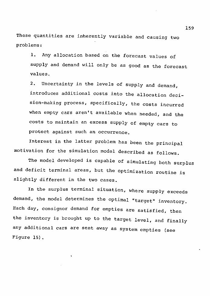
159
These quantities are inherently variable and causing two
problems:
1. Any allocation based on the forecast values of
supply and demand will only be as good as the forecast
values.
2. Uncertainty in the levels of supply and demand,
introduces additional costs into the allocation deci
sion-making process, specifically, the costs incurred
when empty cars aren't available when needed, and the
costs to maintain an excess supply of empty cars to
protect against such an occurrence.
Interest in the latter problem has been the principal
motivation for the simulation model described as follows.
The model developed is capable of simulating both surplus
and deficit terminal areas, but the optimization routine is
slightly different in the two cases.
In the surplus terminal situation, where supply exceeds
demand, the model determines the optimal "target" inventory.
Each day, consignor demand for empties are satisfied, then
the inventory is brought up to the target level, and finally
any additional cars are sent away as system empties (see
Figure 15).

160
Loads (L)
Consignor Demand for Empties (D)
System Empties (to deficit areas)
FIGURE 1541
SURPLUS TERMINAL (D < L)
In a deficit terminal area demand is greater than the
number of loads terminated, requiring that additional empties
be trans-shipped to the terminal area so that in the long run,
empty demand and supply are in balance (see Figure 16).
Consignee
L( )E Loads > t;\
(L) / \.:__)
System Empties t (from surplus areas)
Consignor Demand ___ _,,,..~ for Empties (D)
FIGURE 1641
DEFICIT TERMINAL (D ) L)

161
In this case, there is little likelihood that the
inventory could be replenished by the incoming empties, since
supply just equals demand on average. An initial inventory
of cars, E0, is therefore provided at the beginning of the
simulation period, and the model determines the optimal value
for this initial inventory level. The theoretical results
are derived from the deficit terminal structure, described
graphically below:
L.l 1 -RL l.
L.N =LL·j L.2 2 T E T - RL L. l. . l. l.
Rn~l. i J L.n l. L~
D )o= E.
REl~ l. 1
E. l.
E.m =LE·j E.2 R 2 l. . l. l. E J
E·m Rm l. E
FIGURE 1741
SIMULATED DEFICIT STRUCTURE
On each simulation day, n groups of loaded cars, Lj, are
generated. While the number of cars in an individual group
may vary from day to day, the average value of the total daily
loaded cars, LN, is constant over the simulation period. Like
wise m groups of empty cars are generated daily, and the average
value of the total over the simulation period, EM, is also con-
stant.

162
Each individual group of loaded or empty cars travels to
the terminal according to trip time distributions (denoted
here by RLj and REJ) which can be different for each group.
Each day, the actual travel time for each group of cars is
selected randomly from the appropriate trip time distribution.
All empty cars arriving on a particular day, i, are used
to satisfy that day's demand for empties, Eid, but all loaded
cars arriving on day i, LiT' must first be emptied and returned
to the terminal. The "time to empty" distribution, Rs, may be
constant or variable, and determines the number of empties,
EiT, that are returned to the terminal on day i. These empties
can also be used to satisfy Eid·
The model is "warmed up" for a period equivalent to the
maximum, q, possible trip time specified by the trip time
distributions. The model then simulates "z" additional days
(the simulation period) and for each day, the cumulative sur-
plus or deficit, Wi, is calculated:
W. = W. l + E.M + E1.T - E.d 1. 1.- 1. 1.
Thus, the cumulative surplus or deficit for day i is
equal to the cumulative surplus or deficit from day i-1 plus
the net balance of empty cars at the end of day i. As
described, an inventory of cars, E0, is provided at the begin
ning of the simulation period and cannot be replenished. The
model determines the optimum E0 which minimizes the terminal
operator's disutility:

163
q+z
Min Ui (EO)
i=q+l
where:
For short simulation time periods, this structure seems
reasonable. Empty car allocation decisions are seldom made
instantaneously, and are not generally responsive to daily
fluctuations in demand or supply. In general, cars are allo
cated some weeks in advance so the use of an unreplenishable
initial inventory over the simulation period appears to be
consistent with actual railroad operations.
The foregoing model is presented as a typical example.
Its application may or may not be appropriate, but is an
example of the current state of the art.
F. PASSENGER FLEET SIZING23
1. Background. The Regional Railroad Reorganization
Act of 1973 mandated the Department of Transportation
to undertake engineering and planning studies in sup
port of improved passenger rail service in the Northeast
Corrider (NEC). In order to obtain estimates of the

164
fleet required to provide the improved service and to
analyze the effect of fleet management strategies, a
study was undertaken to calculate the optimal number of
cars required for design day service in the NEC. A
linear programming model was formulated for determining
fleet requirements for a variety of scenarios, including
several different formulations of the objective function.
Using a demand forecast based on the service standards
prescribed in the Railroad Revitalization and Regulatory
Reform Act of 1976, the minimum fleet size was calculated.
Minimum car-miles per day and maximum load factor were
also found.
Proper fleet management results in a reduced· fleet
size, lower operating costs, and an increase in rider-
ship. Fleet management includes both the scheduling of
trains and the scheduling of the units that make up
these trains.
• 2. System Description. Eleven cities along the NEC
rail line are assumed to be served by improved rail
service. Seven of these cities receive half-hourly
service and the remaining four, hourly service. The
accompanying map identifies the eleven cities and the
level of service at each. In addition, it is assumed
that train length modification can occur at Philadelphia
and New York as well as the two end points, Washington

165
and Boston. The switching points are referred to as
terminals in Figure 18.
The trip times shown in Figure 18 which include
intermediate stopping times, correspond to the require
ments set forth in the Railroad Revitalization and
Regulatory Reform Act of 1976. Since the time gained
by not stopping at a station is negligible (estimated
to be one and one-fourth minutes by the Engineering
Division, Northeast Corrider Project Office), it is
assumed that the skip-stop service has the same running
time as the local service trains. There is a twenty
minute time requirement for reversing the direction of
a car. (Reversing direction of equipment may occur at
any of the four switching points).
A uniform fleet with an average car capacity of
seventy-five passengers is assumed. This corresponds
to the Amfleet equipment and allows one snack bar car
for every four cars. Parlor car service is not con
sidered.
All equipment is locomotive hauled with a maximum
train length of fourteen cars, not including the loco
motive. The maximum train length is determined by the
platform·lengths planned for the improved rail system.
If more than fourteen cars are required to satisfy the
proj~cted demand, a second section is added to the

166 BOSTON
PROVIDENCE
. c: NEW LONDON ..... E C) q- . NEW HAVEN s, ..c: ('\")
STAMFORD D Terminals NEW YORK
0 Major Stations (Half-hourly service) . TRENTON
s; o Minor Stations ..c: ...... (Hourly service)
I PHILADELPHIA
. WILMINGTON c: •.- E C) q- . BALTIMORE S- ..c: ......
WASHINGTON
FIGURE 1823
NORTHEAST CORRIDOR TERMINAL SPACING

167
schedule. All deadheading is accommodated through the
existing schedule.
3. Model Formulation. The system described ·above can
be modeled by a transshipment network whose unit of flow
is one car. In its simplest form, the network has a
node for each potential arrival or departure time at
each city. These nodes are connected by two types of
directed arcs. Storage arcs connect each time node for
each city to the immediately following time node; flow
along one of these arcs represents storage of cars at
a city in the interval between two times. Train arcs
connect a time node in one city to a subsequent time
node in a different city; flows along these arcs repre
sent movement of cars from one city to another in
scheduled trains. Network flows must satisfy constraints
of several sorts: flow must be conserved at every node
(cars do not enter or leave the system); flows along the
train arcs must be great enough to meet demands; and all
flows must be integer and nonnegative.
This network system may be transformed to an equiva
lent set of linear programming (LP) constraints.
(Linear programming represents the most efficient tech
nique for computing an optimal solution.) In more
precise terms, this is done as follows. First, define
the relevant sets:

168
c T = 0 I ••• I -1
the set of cities
the set of time intervals into
s C{(c,t,c' ,t') e c x T x C' x T' I c 'I- c •}
which the day (or other schedule
period) is divided
the schedule: each element rep
resents a train that leaves city
cat time t and arrives at city c'
at t'
Represent the demands by:
dee, [t, t ~ ) O the smallest (integral) number of
cars required to meet demand for
train (c,t,c' ,t') es Express the nodes of the network as:
Ac (tj for all cf c, tc T
The directed arcs representing storage of unused cars
are then:
uc[t]: Ac [t] Ac [(t+l)modr'] for all c€ c, te T The arcs representing movement of cars in trains are:
for all (c,t,c',t')E S
Define an LP structural variable corresponding to
each arc, and representing the flow over the arc:
flow over uc[t], for all cc c, tE T
flow over Xcc•[t,t•J, for all
(c,t,c' ,t') es xcc, [ t, t •]

169
The constraints on network flow are then expressed as
follows:
Cons envaxio« 06 6.f.ow:
uc [<t-1) mod r] + [t1, t]
x rt1t] for all c £ C,tc T cc2 L.: c-
(c,t,c2t2> e s Sa.,t,U,6ac:tlon 06 demand:
xcc' [t.t'] ~dee' [t,t~
Nonnega,Uv..Uy:
Uc [t] ~ 0 1 n:t.eg.l{a.,Uty:
uc [t] integral
Xcc, [t, t '] integral
for all (c,t,c',t') e s
for all etc, e s r
for all CE; C, t~T
for all (c,t,c',t') es Nonnegativity of the x variables is insured by satisfac
tion of demand.
Given that all dee' (t,t~ are integral, a fundamental
property of transshipment problems guarantees that every
basic solution to the above LP is an integral solution.
Consequently, a feasible solution to the above problem
(and hence a feasible allocation of cars to trains) may
be determined directly by application of the (phase 1)
simplex method. Given any linear objective function,
the simplex method will also find an optimal feasible
allocation.

170
Objectives of special interest include the following:
a. Capital cost. The daily cost of amortizing
the passenger-car fleet, here referred to as the
"capital cost", may be considered proportional to
the number of cars in the fleet. Hence, minimizing
fleet size serves to minimize capital cost. A
linear expression for this objective is:
u Q'-1] + c (c,t,c',t')E S
t' < t
This expression counts the number of cars in the
system during the last interval of the day. The
first sum represents the number of cars in storage
during the interval, while the second represents the
number in trains that are running at that time.
b. Operating cost. Costs proportional to the number
of car-miles run in a day, here called "operating
costs", are another logical candidate for minimiza
tion. Letting the distance from c to c' be rncc''
total car-miles per day is equal to the linear form:
I (c,t,c' ,t') t S
c. Load factor. Given fixed demands, it is reason
able to try to maximize system load factor in order
to minimize cost of providing service. By definition,

171
system load factor is:
= passenger-miles I day seat-miles I day
= (passenger-miles I day) I (seats/ car) car miles I day
Since both passenger-miles/day and seats/car are
fixed by the problem, ZLF is inversely proportional
to car-miles/day= ZMILE. Hence, minimizing operating
cost is equivalent to maximizing the system load fac-
tor.
Many desirable extensions and refinements of this
model are presented in full detail in "Models of Rail-
road Passenger-Car Requirements in the Northeast Corrider"
by Robert Fourer. Variations on the network permit the
number of nodes to be greatly reduced and make possible
a distinction between northbound and southbound trains.
Techniques for optimizing two or more objectives sequen
tially or in combination are also developed.
4. Applications. Using an expanded version of the model
that distinguished northbound and southbound trains, it
was possible to minimize turnaround, the changing of
cars' directions at terminal stations. Analysis of the
optimal solution suggested that many cars are needed
only for the Philadelphia-New York segment to satisfy
peak demand northbound in the morning and southbound in

172
the afternoon. This suggests a revised schedule in
which New York-Philadelphia shuttle trains are run at
peak hours, in addition to the usual through trains.
Under simple assumptions, the model may be adapted
to analyze requirements for locomotives as well as for
cars. In the Northeast Corridor application, it was
determined that a single solution minimized both the
number of locomotives required and the number of locomo
tive-miles run.
Many more sophisticated sensitivity analyses are
conceivable if one allows patronage between different
station-pairs to vary at different rates. Other para
metric studies include changing car capacity, altering
turnaround time, and modifying train-size limit rules.
Also, the schedule can be modified.
In addition, other fleet management strategies
(several have been mentioned above) should be investi
gated in similar fashion and comparisons drawn. The
present linear programming formulation is not capable
of handling the more sophisticated express/feeder
arrangement. However, it is likely that there is a
suitable integer programming formulation which would
require different optimization techniques.
Finally, it should be noted that although the model
has been formulated for Northeast Corridor operations,
the same technique could be applied to other portions of
the Amtrak system.

CHAPTER VII
RAIL TRANSIT
Rail transit, including streetcar, light rail, rapid
transit, and regional rail, is a family of transportation
modes with a broad range of service, operational, and cost
charactersitics. Consequently, these modes may be used
efficiently for various conditions. As a result of numerous
technological and operational innovations of rail systems
during the last two decades, rail transit can be highly auto
mated, reliable, and comfortable and can operate with minimal
environmental intrusion. Although several U.S. systems
(e.g., Lindenwold Line and Bay Area Rapid Transit) have some
advanced features, general knowledge and understanding of
rail systems in this country lag behind those of some western
European countries and Japan. Based on a comparison of the
population characteristics of selected European and u.s.
cities with similar population size and density, European
cities generally have a much greater application of rail
transit. Despite extensive research into new technologies,
no new mode has emerged with performance and cost character
istics superior or comparable to rail technology. Thus, to
achieve more efficient and economical transit systems, infor
mation about rail modes must be increased and these modes
must be included among the alternatives considered in transit
planning.

174
The United States was the leader in rail technology and
operation for a number of years several decades ago. However,
while many foreign systems have been vigorously improved and
modernized, U.S. systems have suffered from underinvestment
and a decrease in technical and managerial expertise. The
leading role of the United States was consequently lost after
World War II.
Although the Lindenwold Line in Philadelphia and the New
York, Chicago, and San Franciso rapid transit systems have
some unique features and innovations that do not exist else
where, U.S. rail systems are generally obsolete in their
technology and type of operation. Several observations con
firm this condition:
1. There are few systems in the world that have less
attractive, less safe transit stations than those, for
example, along the Broad Street Line in Philadelphia or
along many routes in New York City.
2. A survey of noise levels of rail rapid transit sys
tems in eleven U.S. and European cities undertaken by
Operations Research, Inc., in 1964 showed that all four
u.s. systems included in ·the survey were on the top of
the list ranking levels of noise.
3. The condition of track on many commuter railroads
in U.S. cities is probably worse than the condition of
any corresponding facilities in Europe or Japan.

175
4. Labor practices in railroad companies are more
obsolete than in any corresponding operations in Europe.
Many regional rail systems are operated by crews of up
to nine persons although two or three would suffice for
modernized operation.
5. The newest streetcar vehicles operating in the U.S.
cities are twenty-two years old; some regional rail
vehicles are over sixty years old.
6. Many systems have limited speed because of unsafe
track conditions, and some cities require every street-
car to make a safety stop before every diverging switch,
a practice abandoned in Europe decades ago.
7. Numerous technical innovations, such as the above
mentioned switches with elastic points, constant-tension
overhead catenary, and fare collection machines, are not
known to exist even by most persons in the rail industry
and operating agencies.
The neglect of rai~ technology and operations in the
United States is also reflected in the extremely expensive
and yet unreliable rolling stock and train controls for our
most recent systems. Several of them have suffered from
rather elementary mechanical and electric failures that result
in excessively frequent service slowdowns and interruptions.
Low reliability is not a typical problem of rapid transit sys
tems. For example, the newly opened rapid transit system in ~
Munich was built by using extensive experience from other

176
cities so that, although the system was entirely new, it had
only two major delays in its service during the first eigh
teen months of operation; both were caused by factors out of
control of the operating agency.
This lagging expertise and lack of information about
many modern technological developments in rail systems and
policies are a serious problem in the United States. Fre
quent justification for ignorance of foreign developments is
given by claims that U.S. cities are different or that
Americans are unique in their love for the automobile. Al
though it is true that conditions are not identical in any
two cities of the world, the claim that solutions from other
countries do not apply to U.S. cities is incorrect.
Most frequent is the simplistic argument that rail transit
is justified only in large cities that are densely populated;
European cities use rail systems because their population
density is greater than that of U.S. cities. Neither of these
two arguments is correct. First, population size and density
are not sufficient factors to determine feasibility of rail
systems: A medium-size city with low average density may have
either topography or high-density corridors that require rail
transit. Second, European cities that use rail modes exten
sively do not have more people or more dense populations than
many U.S. cities that have no rail systems.
The belief that Americans are unique in their love for
the automobile is also highly questionable because in most

177
West European countries automobile registrations increased
several times during the 1960's (in Italy more than six
times from 1960 to 1970). However, although this automobile
ownership increase in European countries did divert some
passengers away from transit, transit patronage trends differ
considerably from those in the United States. Although there
are many physical, economic, and social differences between
the United States and some European countries, it is quite
clear that the basic policy toward urban transportation,
improving both public and private modes in a coordinated man
ner, has already shown distinct positive results and is
leading toward a stable situation in urban transportation.
The lack of knowledge about rail modes among transporta
tion planners and engineers results in a misinterpretation
of their proper application in urban transportation. u.s.
cities that could efficiently use light rail systems have
been planning systems similar to BART or the Lindenwold Line
and, therefore, incur much higher costs than are rationally
justified. Further buses and busways are planned for many
corridors that would clearly be more efficiently served by
rail transit.68
A. STREETCAR SYSTEMS68
Streetcar systems consist of one, two, and occasionally
three rail vehicles operating mostly on streets in mixed
traffic, sometimes with limited separation from street traffic

178
on private rights-of-way. Although their comfort and dynamic
characteristics are good, when they operate in mixed traffic
their service quality is often unsatisfactory. Street condi
tions generally keep operating speeds below twelve mph. The
comfort, schedule reliability, speed, and passenger attrac
tion of streetcars are consequently similar to those offered
by surface buses and are inferior to those of other rail modes.
The positive qualities of streetcars include a higher
capacity and a more distinct image than that of buses, and
a lower cost for right-of-way than for other rail modes.
Selective application of traffic priority measures including
reserved lanes and provision of some private rights-of-way
(both of which are inexpensive improvements) can greatly
enhance the attractiveness of the streetcar mode. Yet, the
greater facility with which buses serve low-density areas
and the trend to upgrade heavily traveled streetcar lines
into higher quality rail systems have resulted in the con
version of most streetcar lines to either bus or light rail;
consequently, this mode has experienced a general decline in
ridership and a diminishing role in urban transportation.
B. LIGHT RAIL TRANSIT JO' 6?
Light rail transit is an urban electric railway having
a largely segregated but not necessarily grade-separated
right-of-way. Speeds, capacity, and overall performance are
generally lower for light rail transit than they-are for

179
fully grade-separated rapid transit, yet LRT is substantially
superior in capacity and performance to any form of transit
operating on public streets or roadways in mixed traffic.
Because it is not fully grade separated and because it is
not designed to have as high an overall performance and
capacity as rapid transit does, LRT generally costs much
less to construct per route mile. This lower cost allows
LRT to be economically justified in urban areas or in
specific corridors where conventional rail rapid transit is
not feasible either because of cost or demand considerations.
Light rail transit is a medium cost mode that provides
a medium speed service for a medium volume of passengers.
It therefore falls into that cost-service region between con
ventional rail rapid transit and motor bus, yet there is
considerable overlap upward into the traditional cost-service
domain of rail rapid transit and downward into the domain for
which motor buses have been considered most appropriate.
During the past two decades, there have been a number
of novel modes proposed to fill various medium speed and
capacity needs. It has been evident to planners and research
ers, as well as to inventors and promoters, that medium
demand corridors exist in many medium and larger sized metro
politan areas constituting a significant market for these
novel modes. However, any new technological innovation needs
considerable research and development before it can be used
in the marketplace. Highly publicized difficulties of the

180
first operating prototypes of some new modes give cause for
caution before such modes are adopted widely. Yet the need
to service medium density corridors is clear to many planners
and political leaders.
Light rail transit is suitable to fill this role today.
Light rail transit is an evolutionary development of the
street railway and full-scale rapid transit and has some
features of both. Its subsystems have been fully developed
and proved, and there is no need for costly, time consuming
research and development.
Light rail lines in the early days used just what the
name says: light rail. It would be difficult to find any
sixty pound per yard rail remaining, but at one time it was
very common. Many interurban lines were built with seventy
pound rail. The minimum weight T-rail now in common use on
light rail lines is eighty pound.
A desirable standard for light rail operations is one
hundred pound rail. A fairly heavy rail, because it is more
rigid, can help to overcome a poor roadbed. The eighty pound
rail in wide use is just too light, and ninety pound rail is
becoming difficult to obtain. One-hundred pound rail, par
ticularly in the ARA-A cross section, will probably remain
common for many years.
Some rebuilding of existing light rail lines has been
done with much heavier rail. Anything larger than the popular

181
115 pound AREA rail may be a waste of money, unless a larger
section is wanted for greater electrical return and it proves
more economical than supplementary negative cable. The trade
off must take into consideration that the rail will have to
be replaced eventually and that the cable should last indefi
nitely.
Rail gauges for light rail applications have ranged from
meter gauge common in Europe to as wide as five feet four and
one-half inches in the Baltimore street railway system. The
narrower gauges originally were adopted for economy; ties
could be shorter, and the ballast cross section was narrower.
These gauges generally are inadequate for U.S. practice. To
avoid poor riding of cars, narrow gauge rail lines must have
better maintenance than standard gauge lines, particularly
for cross level. The meter gauge light rail lines of Europe
usually are maintained superbly.
The nonstandard wide gauges once fairly common in the
United States and still surviving in Toronto were imposed by
city councils who wished to physically prohibit the operation
of interchange railroad cars in city streets. so-called
wagon gauge, which is about five feet two and one-half inches
survives in Pennsylvania, in both Philadelphia and Pittsburgh.
Although the wide gauges are better than narrow gauges
for controlling sway, they have no particular riding merit
and have cost disadvantages in light railways, for which
four feet eight inches is just about right for the usual

182
light rail car. Wide gauges of five feet six inches, which
are used in Spain and on Bay Area Rapid Transit in San Fran
cisco, are better than standard gauge for today's giant
railroad operations that have very high cars and fast unit
trains, but a general change probably will never be econom
ically justified.
For ease of availability, special work (frogs, switches,
crossings) ought to be standard railroad or heavy rapid
transit types except when tracks are in pavement. When using
the street types of special work intended for paved surfaces,
one must take care that the rail contour and flangeways will
accommodate the wheels of any equipment to be used on that
part of the line. Deep flanges can readily smash street
railway switches; again, any new project should use full-depth
railroad types of paved area special work.
Special elastic switch points and improved frogs have
been developed in Europe and are used widely in light rail
ways. In the United States, use of the spring frog, which
requires conscientious maintenance, has declined. One special
work item that should be considered more often is expansion
points. Expansion points minimize problems with continuous
welded rail (CWR), especially on sharp curves. If CWR with
all its advantages is not installed correctly and is not
maintained to the best standards, it can be terrible for a
light rail line whose cars are sensitive to misalignment.
At the speeds proposed for most new light rail projects, this

183
alignment matter can be very important. In other words, CWR
must be done right or be avoided. Field welding is not as
suitable as shop welding because the latter generally gives
better accuracy of alignment.
Slab track, on which the ties or a substitute method of
support and gauge holding are completely enclosed in one or
more concrete pours, has proved satisfactory in preserving
excellent alignment and minimizing maintenance costs. Pitts
burgh has several examples, some of which have been in use
a long time. Indeed, joint use of private right-of-way by
buses requires this method and pavement up to top of the rail.
The line thus becomes a restricted-use street for public
transit vehicles only. A law enforcement problem is created
in keeping automobiles out. Disadvantages of slab track
include a far higher installation cost than ballasted track
and the difficulty of using track actuated signal systems,
which require special rail-to-rail electrical insulation.
Noise transfer ought to be studied carefully before a decision
is made to install slab track at a particular location. Major
railroads are studying the entire question of track structure
because it is believed that the present standard practices
are inadequate for heavy loads at high speeds. Open types of
slab track with rail and fasteners fully exposed show promise,
and considerable advanced testing is going on in both Europe
and Japan. However, the conventional standards have served
light rail very well.

184
The time proved support for all types of railroad still
is treated hardwood ties on crushed rock ballast. For light
rail, the ties can be smaller than standard railroad practice.
Cross section of six by eight inches is adequate. A length
of eight feet is suitable, but eight feet six inches is more
common. Tie centers can be twenty-four inches; this requires
2,640 ties per mile versus 3,000 ties per mile or more for
heavy-duty railroads. In a light rail application in which
properly selected hardwood ties are used on a well drained
and adequate ballast and in which tie plates are used and
good maintenance practices are observed, the ties should
last an average of forty years.
Stations for light rail facilities can vary all the way
from a mere patch of cleared ground to elaborate enclosed
facilities in a subway or terminal building. The type of
station to be provided is a function of several variables:
passenger volume, train frequency, climate conditions, method
of fare collection, immediate surroundings, and civic require
ments.
One thing to keep foremost in mind when one plans sta
tions for a light rail facility is that most sites should be
able to be upgraded later if conditions warrant. When possi
ble, it is important to obtain control over enough land at
the station locations at the beginning to allow for later
elaboration. Space for parking requirements ought to be a
major consideration in locating some of the stations.

185
Grades of 6 per cent or more both ascending and descend-
ing are common with light rail vehicles. Short grades of up
to 14 per cent are the extreme limit.
Because of low vehicle weight and high power-to-weight
ratio, LRT can handle grades at a faster speed than the
usually heavy trains. The desire to operate long trains in
conventional rapid transit work precludes doing some of the
things that have been done with LRT. The controlling factor
is braking capacity, a feature that easily can be made higher
than standard on light rail vehicles.
Vertical curvature can be rather extreme on LRT compared
to that of conventional rapid transit. Having no requirement
for riders to pass between vehicles, light rail vehicle design
can provide great freedom in vertical curve limits, both sag
and crest. Single vehicles made to the rather short Presidents'
Conference Committee (PCC) truck centers can do amazing things
in this respect. When light rail vehicles (LRV's) are opera
ted in multiple units, the couplers with their drawgear and
radial carriage requirements can tend to restrict the vertical
curves that can be taken. However, this limit is not reached
on any active North American operations.
Articulation can place fairly restrictive limits on
vertical curves, though the new standard light rail vehicle
seems rather liberal in that respect with a limit of 310 feet
crest radius and 460 feet sag radius. Passenger apprehension
of the change in curvature might be greater with articulation.

186
Just about anything reasonable can be done. The decision
involves how much seating capacity to sacrifice to make the
connecting drum larger.
Horizontal curve capability is what sets LRT apart from
conventional rapid transit. Light rail transit was originally
conceived to have a track that could accommodate the right
angle intersections on city streets.
Light rail cars usually have been designed with rounded
ends. This has been done not so much for aerodynamic design
as for clearance on turning, particularly when they are run
in multiple units. Couplers are radial; they swing in a semi
circle rather than ride in a striker box as they do on a
railroad car. When knuckle couplers are used, the capability
of going around curves becomes very high.
Today's light rail vehicles are designed to negotiate
curves of forty-two feet inside rail radius. Anything tighter
than that would place limits on features other than the
coupling or articulation. Car width, location of trucks, and
wheelbase might have to be restricted unduly.
Usually, the most extreme horizontal curves in a light
rail system are in the non-revenue tracks required for revers
ing single-end vehicles at the end of a route. The single
end design is highly desired in markets that demand maximum
seating, and the relative inflexibility and need for turning
trackage of the single-end car can be a favorable trade-off
for its lower first cost and greater number of seats than

187
double-end cars. Loops and Y's can be placed in a relatively
small space because of the forty-two foot radius.
The size and weight of the LRV are usually less than
that of rapid transit vehicles. The Boeing Vertol-UMTA stan
dard LRV currently being built for Boston and San Francisco
is seventy-two feet long and eight and one-half feet wide;
it rests on three trucks; the center unpowered truck is under
an articulated joint. The distance between truck centers is
about the same as it is on the existing single-unit PCC street
cars being used on the same routes. These measure forty-six
feet long and 8.33 feet wide; there is 22.75 feet between
truck centers. This results in a rather long overhang on the
front and rear of the car, the effect of which is minimized
by some tapering of the car ends. Height is typically about
ten feet over the roof, plus one or two feet more for what
ever current collecting device is installed (trolley pole or
pantograph). Some PCC cars were built to lengths of fifty
feet and widths of nine feet. In Europe, cars are usually
narrower and shorter than they are in North America. The spa
ciousness of LRV's permits a wide variety of interior
arrangements. They can be equipped with spartan seating
allowing extensive standing room for high density, short-haul
travel, or they can emphasize comfortable seating for long-
haul suburban traffic. Nearly all new transit equipment is
air-conditioned.

188
Light rail systems typically have articulated six or
eight axle vehicles of multiple unit trains of up to three
four-axle cars. Light rail maximum speeds are in the range
of forty to sixty miles per hour. The obsolescent but still
used PCC streetcar has a maximum speed of forty-two miles per
hour. The top speed of the new standard light rail vehicle
(SLRV) is fifty-five miles per hour. Certain suburban light
rail equipment can attain speeds in excess of seventy miles
per hour, but this is unusual.
Overall schedule speeds for light rail lines on fully
segregated right-of-way generally fall in the fifteen to
thirty-five miles per hour range depending on station spacing
and degree of segregation. If the track is in the street,
schedule speeds will be much lower; they will range generally
from ten to fifteen miles per hour.· Maximum speeds will be
limited to whatever the allowable speed is for traffic in the
street.
Acceleration of three miles per hour per second (mph/s)
is a generally accepted industry standard based on what a
typical standing passenger can tolerate. The PCC streetcar
was designed and built to attain a rate of 4.75 mph/sin the
lower speed ranges; some operating properties reduced this
somewhat, however. For instance, San Francisco's PCC cars
are set for 4.25 mph/s.
Acceleration of the Boeing LRV has been found to be 2.6
mph/s, but it holds this rate to a higher speed. Therefore,

189
its overall performance is expected to be quite attractive
when station spacing allows the vehicle to attain its fifty
five miles per hour running speed.
Past accomplishments indicate that it is technically
possible to attain whatever rate of acceleration is desired
within the limitations of adhesion. The tolerance of stand
ing passengers and the various costs related to installing
the desired power are the controlling factors.
The simplest traffic control for light rail systems is
on-sight control, which means that the operator of a train
or car merely operates the vehicle an estimated safe breaking
distance behind the preceding vehicle. This type of control
will be retained on the street portions of both Boston and
Muni routes, and is also commonly used on street or surface
sections of European light rail lines.
A higher type of traffic control is provided by block
signals that provide a visual indication to the train operator
of the condition of the block ahead or speed at which to run
or both. Block signals are commonly used on private rights
of-way (including elevated and subway sections) of many present
light rail lines. These depend on the operator's observing
and responding to visual indications on wayside signals.
Several European light rail lines using wayside signals
have an intermittent inductive train stop that triggers an
emergency brake application if a train attempts to pass a
red signal. This type of stop enforcement is unaffected

190
by encounters with other vehicles or debris in the street.
Cab signals may be readily adapted to the light rail
mode; in fact, this is being done for the Market Street Sub
way portion of Muni. The cab signal concept has been used
for many years by certain railroads and has been applied to
a number of rapid transit lines during the last decade.
Normally a cab signal system will indicate visually to the
train operator the speed at which to operate. The system
also will apply the brake to slow or stop the train if it is
operated in excess of the indicated allowable speed. The
cab-signal concept provides all-weather capability because
the train operator does not need to see wayside signals.
This allows full speed operation in snow, rain, or fog.
The primary virtue of cab signals is that they improve
performance. A train (or vehicle) need not proceed at
restricted speed from, say, a yellow signal to the next sig
nal if the signal should clear to green. With a cab signal,
the operator immediately knows the condition of the block
ahead and can accelerate or decelerate accordingly. In addi
tion, where visibility is impaired, as in a subway section
with curves, cab signals provide the operator with a contin
uous indication of the block or blocks ahead. Cab signal
systems therefore provide somewhat higher capacity and safety
over wayside signal systems.
It is natural in a cab signal system to progress to fully
automatic train operation. This would add the capability of

191 automatic station stops in which deceleration to a stop and
positioning at a platform would be programmed as has been
done on several recently implemented rail rapid transit lines.
No light rail system yet implemented or proposed has opted
for a fully automatic train operation.
A light rail route can be designed to economically
handle up to 12,000 or 18,000 passengers per track per hour.
Higher numbers are attained by using multiple-unit trains.
For instance, the seventy-two foot long Boeing LRV would have
a rush-hour capacity of about 150 to 180 passengers, depend
ing on seating arrangements and assumed space per standee. A
three vehicle train thus would accommodate easily 450 passen
gers. At a two minute headway, thirty such trains could pass
a given point in one hour. This results in an offered capacity
of 13,500 passenger spaces per hour. A four vehicle train
would handle 18,000 passengers per hour, although at this
volume of traffic, fully grade-separated rail rapid transit
may be a better choice.
Several existing light rail systems carry 10,000 to 15,000
passengers per day on a given route. Such volumes require
that only 2,000 to 4,000 passengers be carried during a rush
hour, which is attained easily with one and two car trains on
three to five minute headways. Yet these passengers enjoy a
speedy ride not attainable by transit vehicles in mixed traf
fic. This is what generates higher per capita LRT ridership
in a given corridor.

192
A light rail system can be designed for modest traffic
and can be upgraded from time to time as demand increases.
It is not necessary to invest large amounts of money in an
initial system. Investment can be distributed over a long
period of time and grow in increments as the need arises.
Several options in vehicle and station characteristics give
a designer numerous investment choices and combinations.
A system can be designed for moderate headways of, say,
five minutes. As traffic increases, train length can be
increased from one to two or even three or more vehicles.
Concurrently, stations must be lengthened (which may require
substantial investment) and substation capacity increased to
provide power for longer trains. On the other hand, it is
sometimes easier to decrease headways from, say, five minutes
to two minutes with one or two vehicle trains before addi
tional capital is invested in lengthening stations and
increasing substation capacity. It also might be necessary
to alter significantly a signal system when changing from a
five to a two minute headway. Short trains on short head
ways and longer trains on longer headways have their place.
Both may be needed.
REGIONAL RAIL68 c.
Regional (commuter) rail systems consist of large, high
speed rail vehicles operated individually or in trains,
usually by railroad companies. The service is characterized

193
by long average trip lengths, large interstation spacing, and
very comfortable riding. Passenger volumes are heavily
peaked, highly directional, and predominantly suburb-to-CBD.
Most regional rail networks in our cities consist of a number
of radial lines from the CBD and have stations located at
suburban town centers. Kiss-and-ride, park-and-ride, bus
feeders and walking are used as access modes. Central city
stations are often combined with intercity rail stations,
but they are limited in number and provide little downtown
coverage.
In recent years another kind of regional rail system has
emerged. When there are alignments, station spacings, and
speeds similar to those for commuter rail, these systems have
frequencies of service and CBD distribution similar to those
for.rapid transit. Examples include Germany's S-Bahn, Paris'
R.t.R., Philadelphia's Lindenwold Line, and San Francisco's
BART. These modern regional rail systems give metropolitan
regions with many distinct satellite communities an excellent
regional transportation network.
Because regional rail service is usually provided by
railroad companies, the cars are usually larger and heavier
than rapid transit cars and have very high seating capacity
(in double decker cars, up to 160 passengers/car). The
tendency in new cars is to use two or three vehicle married
units in trains of up to ten vehicles. The service quality
of regional rail is generally high for European systems, but

194
it is quite variable among American systems that have been
severely hurt by inadequate financing, lack of modernization,
disinterested management, and obsolete labor practices.
The capital investment required for regional rail depends
heavily on whether modernization of an existing railroad line
or an entirely new regional rapid transit system is considered.
The former usually involves very low costs (track renovation,
electrification, and station construction); the latter,
because of high alignment standards, requires an investment
cost higher than that for rapid transit. Recent vehicle costs
have been about $400,000. Operating costs vary greatly with
labor practices, i.e., size of crew, which is typically much
larger than the operation actually requires, particularly on
U.S. systems.
13 68 D. RAIL RAPID TRANSIT '
Rapid transit consists of long four axle rail vehicles
operating in trains on completely private rights-of-way that
allow high speed, high reliability, high capacity, rapid
boarding, and fail-safe operation.
Rapid transit has the highest service quality of all
transit modes. Recorded capacities of lines with stations
have been as high as 45,000 passengers per hour. Some of the
recently opened systems (in Sao Paolo and in Paris) have been
designed for a capacity of 80,000 passengers per hour.
Capacity volume, however, results in low comfort. The maximum

195
seated capacity is approximately 30,000 passengers per hour,
but most systems are designed for volumes from 8,000 to
25,000 passengers per hour.
Most rail transit lines in U.S. cities are basically
radial with limited coverage of city centers (except in
Manhattan). Modern European rapid transit systems, however,
have been designed with networks covering large central
areas, thus, also offering service for the medium and short
trip and the longer urban commuter trip. Area coverage in
the suburbs is often helped by park-and-ride or kiss-and
ride transfer facilities or by bus feeders. In part, these
supplementary services are required because of low popula
tion densities and rapid transit's longer station spacings
in these areas. Generally, average trip lengths on rapid
transit systems are longer than those on surface transit,
ranging from three to seven miles.
The well known drawback of rapid transit is its high
capital cost, brought about mostly by the need to provide
fully private rights-of-way. Furthermore, costs of auto
mated vehicles are high. However, because of its high
service quality, rapid transit has a greater capability to
attract passengers when compared to other modes. This is
the major goal for any transit service.
With respect to operations, rapid transit systems are
rather diversified. Modern systems operate trains of any
length that the station platform can accommodate without

196
full automation and with one-person crews (e.g., eight car
trains in Hamburg since 1957, six car trains in Philadelphia
since 1969). Stations may be operated without personnel by
using remote closed circuit TV surveillance (Lindenwold
Line). Most U.S. rapid transit systems, however, still use
trains that have two-person crews (up to four persons in
Boston) plus station personnel. When there is a modern type
of operation and efficient management, however, rapid tran
sit can be highly labor productive; the Lindenwold Line
carries 171 daily passengers per employee (including admini
strative personnel and police).
The latest systems have extensive train automation that
also allows some operational improvements and savings in
energy and vehicle maintenance. These are significant in
high capacity systems, but for other systems the benefits
from automation often do not outweigh the increased cost and
reduced reliability at least as long as the train crew is
retained. Elimination of the last crew member on rapid tran
sit systems is probably achievable with relatively minor
innovations of control and operations. There is presently,
however, no serious work in that direction, although unproven
automated technologies are being investigated. Consequently,
the highly automated rapid transit systems in operation today
(e.g., Bay Area Rapid Transit) require a considerably higher
investment cost than do nonautomated systems. But, they do
not have the reduced operating cost and higher frequency that

197
full automation could bring.
Most rapid transit system cars are driven by electric
traction motors that are contained on each car. The source
of energy is wayside electric power distributed through a
third rail or overhead catenary wire. Contact shoes or
pantographs, as appropriate, function as the power pickups
for the car. The traction motors are generally mounted
within the vehicle truck. There may be one or two motors per
truck, or two to four per car. Four motors up to 150 horse
power each, per car are possible. Motors may be alternating
or direct current, although most transit systems use direct
current. The motor sizes are determined as a function of
car weight, design speed criteria, and design acceleration
rate requirements.
The consist (number of cars) varies as a function of
system operating ~equirements and will generally vary from
two to ten cars. These requirements are usually influenced
by peak versus off-peak traffic demands. Often, cars are
semi-permanently coupled in married pairs, which consist of
two cars that share certain auxiliaries such as air compres
sors and communication systems. Although this provides
certain economies in car construction and maintenance, the
two cars may only be operated as a pair. Some systems, such
as the MUCTC in Montreal, operate a three car consist. Large
transit systems may operate trains 600 feet long or longer
and use ten to twelve cars during peak traffic periods.

198
Weight will vary with the size of the vehicle; however,
it will also vary as a function of construction materials.
Cars with aluminum bodies, for example, are generally
regarded as lightweight when compared with stainless steel
bodies. Vehicle tare weights for rapid transit service will
generally range from 50,000 to 80,000 pounds.
The most common type of vehicle truck is a two axle,
four wheel type. The wheels are steel flanged for operation
on steel rails. Because of the steel wheel-steel rail noise
problem in the older portions of the Paris Metro, which con
tains short radius curves, the French developed a pneumatic
rubber tired truck. This design concept is now in use in
some parts of the Paris Metro and in the new Metros in
Montreal and Mexico City. Two rubber tired wheels are mounted
on each of the two axles per truck. The wheels ride on a
concrete or steel track. The trucks include horizontally
mounted, rubber tired wheels operating against sidewalls of
the guideway to steer the vehicles.
Advantages claimed for the rubber tired systems are
reduced noise on short radius turns and the ability to oper
ate on steeper grades than with flanged steel wheels.
Because of the construction features and number of compo
nents of the pneumatic rubber tired trucks, their weight and
rotational inertia are significantly higher than for flanged
steel wheel trucks. In addition, the limitations of load
bearing capacity of the rubber tires result in significantly

199
shorter car lengths than the allowable maximum for steel
wheeled cars. Another disadvantage of rubber tired trucks
is the higher rolling friction and hysteresis losses common
to any rubber tired vehicle. Collectively, these losses,
together with a greater car weight per passenger, result
in total system traction power requirements that may be more
than 50 per cent greater than for steel wheeled vehicles on
systems with similar track profiles.
For safety considerations, most rapid transit cars have
multiple braking systems. These include friction shoe or
disc brakes and usually some form of electric braking. In
electric braking {dynamic or regenerative), the traction
motors are switched to function as generator~ during the
braking mode. Where dynamic brakes are used, the electric
energy generated by the conversion of the train's kinetic
energy in bringing the vehicle to a stop is discharged to
on-board register grids.
One of the more recent advances in transit vehicle pro
pulsion-braking systems is the use of a regenerative braking
system. Although this system is similar to a dynamic braking
system insofar as the switching of the traction motors to
operate as generators is concerned, part of the generated
energy is then used by on-board auxiliaries. An alternative
system permits return of the electrical energy to the contact
rail for possible use by other trains. Regeneration can
reuse 25 per cent or more of the available braking energy of

200
trains. Since, on the average, the braking energy accounts
for almost 50 percent of the total energy lost in a rapid
transit system, reuse of some of that energy and resultant
reductions in heat dissipation can be effected. Therefore,
a regenerative braking concept is highly desirable for energy
conservation. The effective use of a regenerative braking
system is limited only by present technology. Further
advances in compatible electrification and power control sys
tems are necessary before the full benefits of regeneration
can be realized.
BART69
In spite of operational difficulties, the BART (Bay
Area Rapid Transit) system in San Francisco is worth describ
ing as an example of a system with features common to both
E.
commuter rail and rail rapid transit.
The BART system is seventy-one miles long, serving four
major corridors radiating from the central cities of San
Francisco and Oakland on the opposite sides of San Francisco
Bay. Oakland and San Francisco are connected by the under
water Transbay Tube. From Oakland, service is provided north
to the cities of Berkeley and Richmond, east to the rapidly
growing suburban areas of Contra Costa County beyond the
Berkeley Hills, and south to suburban Alameda County. The
remaining line runs southwest from San Francisco to Daly City
on the border of San Francisco and San Mateo County.

201
In 1975, the population of the three counties (San
Francisco, Alameda, and Contra Costa) making up the BART
District was approximately 2.4 million persons. Roughly 1.4
million persons lived within one mile of a BART line.
Approximately twenty miles of the system are located
underground, twenty-four miles on elevated structure and
twenty-seven miles at grade or on earth embankments. There
are a total of thirty-four stations, fourteen of which are
located below ground.
BART was designed explicitly to provide fast, comfort
able, high-quality transit service which would be competitive
with the automobile for relatively long distance commuter
trips. Its design calls for high speed operation under auto
mated control. Station spacings in suburban areas average
between two and four miles, with somewhat closer intervals
in downtown Oakland and San Francisco. These spacings, which
are somewhat longer than on most conventional rail transit
systems, permit a maximum design speed of eighty miles per
hour, with an average operating speed (including stops) of
thirty-eight miles per hour. Minimum design headways through
the Transbay Tube during peak ·periods were set at two minutes,
with provision for direct, "no-transfer" service to downtown
Oakland and San Francisco on all four lines.
BART's designers placed considerable stress on creating
a pleasant environment for the traveling public. The sta
tions are constructed to extremely high standards, and reflect

202
a variety of architectural styles. Each station includes
elevators for use by the handicapped.
BART cars are attractive and comfortable. They are air
conditioned, carpeted, and have upholstered seats, tinted
windows and a public address system for announcements of
stations and transfer points. Each car seats seventy-two
persons. Individual trains may vary in length from two to
ten cars. It was originally intended that service would be
sufficiently frequent to permit all passengers to be seated.
Fares on BART range from twenty-five cents to $1.45,
based on the distance traveled. This fare schedule represents
an average increase of approximately 21 per cent over the
original fare levels adopted when BART first began operations
in 1972. The revised fare structure was instituted in Novem
ber 1975, with fares generally being increased for long trips
and decreased for short trips.
BART is equipped with an automated fare collection sys
tem, involving the use of magnetically encoded tickets based
on the concept of a "stored fare". Passengers may buy tickets
in any amount from twenty-five cents up to twenty dollars,
and use the same ticket for one or more journeys on the sys
tem until its total value is used up.
Parking lots are provided at twenty-three BART stations,
primarily in suburban areas. The capacity of these lots
ranges from 240 to 1,400 cars. Their combined capacity is
approximately 19,000 spaces. All suburban stations have

203
reasonably good highway access.
The area served by BART is also served by two major bus
companies: the San Franciso Municipal Railway (MUNI) in
San Francisco itself, and the Alameda-Contra Costa Transit
District (AC Transit) on the east side of San Francisco Bay.
Both MUNI and AC Transit provide feeder bus service to BART
stations as part of their regular operations. In addition,
AC Transit provides specialized feeder service contracted by
BART to several stations in the outlying suburbs on the east
side of the Bay.
One of the major objectives underlying the design of
BART was the relief of peak period highway congestion. Each
of the four BART lines roughly parallels a major freeway
corridor, although often at some distance from the freeway
itself. Two of the most congested sections of highway are
the San Francisco-Oakland Bay Bridge, paralleling the BART
Transbay Tube, and the Caldecott Tunnel, carrying California
Highway 24 under the Berkeley Hills parallel to the BART Con
cord Line.
Throughout the approximately four year period which has
elapsed since the opening of the Fremont Line in September
1972, BART has experienced continuing problems with the
reliability of its equipment. These have seriously con
strained the level of service which could be provided,
particularly with respect to the reliability of service and
the provision of adequate peak period capacity.

204
The technical issues involved are extremely complex.
No attempt will be made here to discuss them in detail. They
fall into two general categories: problems with the BART
cars themselves and the as yet inadequate reliability of the
automatic train control system.
Significantly higher than anticipated failure rates have
been encountered with the train equipment, leading to unsched
uled maintenance problems, service disruption, and a shortage
of BART cars. In March 1976, for example, the average per
centage of BART cars available for service at any given time
was approximately 50 per cent; BART operations were designed
on the assumption that car availability would be at least 80
per cent.
The most common failures involved the car's propulsion
and braking systems, the on-board automatic train control
equipment, auxiliary electrical and communications equipment,
vehicle suspension and door equipment.
BART's policy is to "recall" to a repair yard any train
that contains a car with a serious malfunction. Where feasi
ble, the train is returned to service after the defective
car has been removed; in other cases a new train is dis
patched to replace the one that was recalled. During the
first three months of 1976, an average of fourteen trains a
day were recalled. BART's service schedule at that time
required thirty operating trains. Thus, on an average day
slightly less than half of the total number of trains required

205 for service had to be recalled for some form of emergency
maintenance.
To date, the California Public Utilities Commission has
found that the BART automatic train control system, essential
to low headway operations, is insufficiently reliable. Until
an adequate level of reliability is achieved, the Commission
is requiring that BART maintain a full station separation
between trains. That is, it is not permissible for one train
to leave a station until the inunediately preceding train has
left the next station down the line. With the relatively
long station spacing on the system, this effectively limits
minimum headways under current operations to approximately
twelve minutes on each line and six minutes through the
Transbay Tube.
BART currently carries approximately 132,000 passengers
per day. This is equivalent to between 2 per cent and 3 per
cent of the total person trips made within the BART service
area during the hours of BART operations.
BART's current ridership is roughly half that which was
originally projected for the full system assuming that it
was completely operational by the year 1975. It must be
borne in mind, however, that this ridership has been attained
over a period when the system was able to provide only a
significantly lower level of service than that originally
projected.

206
Major increases in ridership have occurred following
each successive increase in service. The most significant
increase occurred with the opening of Transbay service in
September 1974. It is interesting to note that, following
each such immediate increase, patronage has tended to remain
relatively stable or to decline slightly. There has not been
any significant, sustained growth in ridership for a given
service level. Introduction of evening service resulted in
a total increase in patronage of approximately 4.2 per cent
over the preceding month. The average increase in fares of
21 per cent implemented in November 1975 resulted in a decrease
in patronage of approximately 3 per cent.
The only significant exceptions to this general pattern
are associated with two major transit strikes affecting the
AC Transit and MUNI bus services in August 1974 and April 1976,
respectively, and the severe gasoline shortages in early 1974.
During each of these periods, there was a sharp but short
lived increase in BART ridership.
BART patronage is dominated by commuting to and from work.
Such travel accounts for over two-thirds of the total trips
made on the system, with the predominant direction of this
movement being into downtown San Francisco.
Consistent with this pattern, ridership tends to be
heavily concentrated in the morning and evening peak periods:
in May 1975, ridership in the four hours making up the
morning and evening peak-periods averaged approximately
207
60 per cent of total daily patronage.
Ridership varies considerably between different seg
ments of the system. Slightly less than half of all BART
trips are made by the Transbay Tube. Patronage is highest
between stations on the Concord Line and San Francisco, and
lowest for travel among the five central Oakland stations.
In general, the system is used more for long rather than
short trips. The average total travel time for a journey
involving the use of BART is forty-six minutes; less than
6 per cent of all trips are under sixteen minutes. This
pattern reflects strongly BART's geographic orientation and
its emphasis on improving service to the outlying portions
of the region.
F. SUMMARY68
Table III gives some important characteristics for each
of the four rail mode categories. These features define the
modes and distinguish between them. In summarizing, two
points are reemphasized.
1. Rail transit is a family of modes, ranging from the
operating and service characteristics of the streetcar
to those typical of rapid transit and regional rail sys
tems. Depending on local conditions, individual rail
modes can be efficiently used for many conditions in
medium and large cities.

208
TABLE V 68
TECHNICAL AND SYSTEM CHARACTERISTICS OF URBAN RAIL MODES
Item Streetcar Light Rail Rapid Transit Regional Rail
Fixed Facilities
Exclusive right- of-way, percent 40 40 to 90 100 90 to 100 Way control Visual Visual/signal Signal Signal
Fare collection On vehicle On vehicle or At station At station at station or on vehicle Power supply Overhead Overhead or Third rail Overhead or rail; Any type; or overhead third rail low or high,
fully controlled
Station Platform
Height and access control Low
Any type; low or high; fully controlled
Any type; Fully controlled;low or high high level level
Vehicle Characteristics
Minimum operational unit 1 1 (4-axle) 1 to 3 1 to 3 Maximum train composition 3 2 to 4 (6-axle) 6 to 10 6 to 10 Vehicle length,m 14 to 20 20 to 33 15 to 23 20 to 26 Vehicle capacity, seats/vehicle 16 to 40 16 to 80 36 to 84 80 to 125 Vehicle capacity, total/vehicle 80 to 180 80 to 335 100 to 250 100 to 290
Operational Characteristics
Maximum speed, km/h 60 to 70 60 to 125 90 to 130 90 to 160 Operating speed, km/h 10 to 25 20 to 45 25 to 60 30 to 70

TABLE V (continued)
Item Streetcar Light Rail
Maximum frequency
Peak hour, joint section/h 140
Off-peak, single line/h 5 to 12
Capacity 10,000
Reliability Poor
System Aspects
209
Rapid Transit Regional Transit
40 to 120 20 to 40 6 to 30
5 to 12 5 to 12 1 to 4
3,000 to 18,000 6,000 to 30,000 10,000 to 40,000 Good Excellent Excellent
Network and area coverage
Good CBD Dispersed, coverage; good area branching is coverage common
Station spacing,m 250 to 500 350 to 800
Average trip length
Short-to medium
Relationship to other modes
Can feed higher capacity modes
Medium-to-. long
Park-and-ride, Kiss-and-ride, Bus feeders possible
Predominantly radial; some CBD coverage
500 to 2000
Medium-to long
Park-and-ride, Kiss-and-ride, Bus feeders
Radial, limited CBD coverage
1200 to 4500
Long
Outlying: Park-and ride, Kiss and-ride, Bus feeders, CBD, Walk, Bus, Light rail

210
2. The combination of service and cost characteristics
offered by different rail modes overlaps, as shown in
Figure 19. There is no boundary, for instance, between
the streetcar and light rail categories. Similarly,
light rail can be designed to function much like rapid
transit and to be gradually converted to it. When its
scale is magnified, rapid transit can become a regional
rail system.
For these reasons, generalizations regarding rail sys
tems with respect to both cost and service characteristics
(e.g., rail systems are expensive) are in most cases incor
rect, and they should not be used.

•r .-- "' ::s er QJ u - > s; QJ V)
211
*Represents a set of mode features including speed, availability, comfort, convenience, safety, user cost and security
Investment Cost
FIGURE 1968
RAIL TRANSIT MODE COMPARISONS

BIBLIOGRAPHY

212
BIBLIOGRAPHY
1. American Railway Engineering Association Manual of Recommended Practice For Railway Engineering· Construction and Maintenance. Volume I and Volume II. Chicago: American Railway E~gineering Association, 1972.
2. American Railway Signaling Principles and Practices, Chapters 1-6, 15, 21. Chicago: Signal Section, Association of American Railroads, 1948-59.
3. Armstrong, John. Track Planning for Realistic Operation. First Edition. Milwaukee: Kalmbach
, . Publishing Company, 1963.
4. Athern, Robert G. "Age of Steel," American Heritage New Illustrated History of the United States. (1st Ed.), Vol. X, 814-898. New York: Dell Publishing Company, 1963.
s. Bezkorovainy, Georgy and Robert G. Holsinger. "The Use of STOP Signs at Railroad Crossings," Traffic Engineering Magazine, (November, 1966), 54-59.
6. • "Optimum Hazard Index Formula for Railroad Crossing Protection for Lincoln, Nebraska." February, 1967. (Mimeographed.)
7. Car and Locomotive Cyclopedia of American Practices. Third Edition. New York: Simmons Boardman, 1974.
8. Chandler, Alfred D., Jr. First Big Business. and World, 1965.
The Railroads:·The Nations New York: Harcourt, Brace,
9. Conducting Transportation. Washington, D.C.: Account ting Division, Association of American Railroads, August, 1960.
10. Code of Car Service Rules, Code of Car Hire Rules. Circular No. OT-10-E. Washington, n.c.: Associ ation of American Railroads, 1977.
11. Code of Trailer and Container Service Rules - Per Diem Rules. Circular No. OT-36-C. Washington, D.C.: Association of American Railroads, February, 1974.

213
12. The Consolidated Code of Operating Rules. Butte, Anaconda and Pacific Railway Company and others. June, 1967.
13. Danziger, Norman H. "Energy Optimization for Rail Public Transit Systems," pp. 31-39. Bulletin 552, Transportation Research Board. Washington, D.C.: Transportation Research Board, 1975.
14. Daughen, Joseph and Peter Binzen. The Wreck of The Penn Central. Boston: Little, Brown and Company, 1971.
15. Dick, M. H. and R. E. Dove. "Broken Rails: Progress in a Long Battle Against Long Odds," Railway Age, (March 11, 1974), 16-18, 22 • .
16. Dick, M. H. "Memo to Management," Railway Age, (January 13, 1975).
17. Dove, R. E. "Chicago and Northwestern Increases Its Rail-end Welding - Adopts Four Part Maintenance Plan," Railway Age, (March 8, 1974), 30-31.
18. Ephraim, Max, Jr. and H. A. Williams. Modern Two Cycle Diesel Engine." (Mimeographed.)
"A Look at a November 29, 1951.
19. Ephraim, Max, Jr. and A. N. Addie. "Diesel Traction in North America." March 10, 1975. (Mimeographed.)
20. "The Future Trends in Railroad Motive Power in the United States." December 2, ·1976. (Mimeographed.)
21. "Falling Dominoes," Forbes Magazine, (May 15, 1977), 81-82.
22. Fantel, Hans. "Murder of the Orient Express," Popular Mechanics Magazine, (April, 1977), 71-75, 172
23. Fourer, Robert, Judith B. Gertler, Howard J. Simkowitz. "Optimal Fleet Sizing and Allocation for Improved Rail Service in the Northeast Corridor," December, 1976. (Mimeographed.} ·
24. Fuller, John W. "Policy Issues in State Rail Planning," December, 1976. (Mimeographed.}

27.
·28.
29.
30.
214
25. Hay, William W. Railroad Engineering. New York: John Wiley and Sons, Incorporated, 1953.
26. Hickerson, Thomas A. Route Location and Surveying. Third Edition. New York: McGraw-Hill, Incorpo rated, 1953.
Horonjeff, Robert. Second Edition. rated, 1973.
Planning and Design of Airports. New York: McGraw-Hill, Incorpo-
Kienlen, T. w. "Recycling Railroad Ties Saves Timber, Oil," The Christian Science Monitor, December 12, 1976.
Knutson, Reid M. "Resilient Response of Railway Ballast,." Washington, D.C., January, 1977. (Mimeographed.)
Landgraf, Robert J. "Light Rail Permanent Way Re quirements and Sources." Special Report 161, Transportation Research Board. Washington, D.C.: Transportation Research Board, 1975.
31. Lyon, Peter. To Hell in a Day Coach. New.York: Grosset and Dunlop, 1968.
32. Matzzie, Donald E. and Herbert B. Weinblatt. "Light Density Railroad Line Abandonment: Scaling the Problem." January, 1977. (Mimeographed.)
33. The Maintenance of Way Cyclopedia. Third Edition. New York: Simmons Boardman Publishing Corpora tion, 1921.
34. Middleton, William D. "Electrification, Is It Going To Happen?" Railway Age, {March 10, 1975), 28-37.
35.
36.
• "Santa Fe's Barstow: A New Yard With New Railway Age, (February 24, 1975), 16, 17, Ideas,"
22, 23.
Nelson, J.C. "Railroad Transportation and Public Policy." Washington, D.C.: The Brookings In stitution, Task Force on Railroad Transportation, 1959.

215
37. The Official Railway Equipment Register. Vol. 90, No. 1. New York: The Railway Equipment and Pub lications Company, January 1, 1974.
38. Overton, Richard c. Burlington Route, A History of the Burlington Lines. New York: Alfred A. Knopf, 1965.
39. Paquett, Radnor J., Norman Ashford, Paul H. Wright. Transportation Engineering, Planning and Design. New York: The Ronald Press Company, 1972.
40. Pauly, Michael. "End of a (Postal) Era," Des Moines Sunday Register, June 19, 1977.
41. Phillip, Craig E. and Joseph M. Sussman. "The Appli cation of an Inventory Model to the Railroad Empty Car Distribution Process," January, 1977. (Mimeographed.)
42. Pillen, Dan. "The Rock Island: Now on a Bumpy Road to Recovery," Des Moines Sunday Register, March 20, 1977.
43. Railway Accounting Rules. Washington, D.C.: Account ing Division, Association of American Railroads, Economics and Finance Department, January 1, 1977.
44. "Railroad Revitalization and Regulatory Reform Act of 1976," Public Law 94-210, 94th Congress S 2718. 45 USC 801, February 5, 1976.
45. Raymond, Gerald P. "Research on Rail Support Improve ment." Washington, D. c., January, 1977. (Mimeographed.) ·
46. Raymond, Gerald P., Christopher J. Boon, Richard w. Lake and Vishnu A. Diyaljee. "Characteristics of Acceptable Railroad Ballast." Washington, D.C., January, 1977. (Mimeographed.)
47. Rail Merger Stud~. Washington, D.C.: Rail Services Planning Office, February, 1977.
48. Rail Planning Manual. Volume I. Washington, D.C.: Federal Railroad Administration, 1977.
49. Sampson, Ray J. and Martin T. Farris. Domestic Trans portation. Boston: Houghton-Mifflin Company, 1966.

216
SO. Seamon, James H. "TRB Rail Activities," Transporta tion Research News, (November-December, 1976).
51. Simon, Paul. "U. S. Buying and Repairing Rail Lines," The National Observer, reprinted in the Des Moines Register, (April 12, 1977).
52. Sinclair, Thomas J. "Railroad," The World Book En cyclopedia, XVI, 106-117, Chicago: Field Enter prises Educational Corporation, 1967.
53. Stevers, Martin D. Steel Trails. New York: Grosset and Dunlop, 1933.
54. Tayalyi, Shiraz D. "Track Sbpport Systems Parameter Study." Washington, D. C., January, 1977. (Mimeo graphed.)
55. "The Ten Critical Issues in Transportation, " Trans portation Research News, (November-December, 1976), 2-4.
56. "Union Pacific Railroad Company Book of Standard Draw ings," Office of the Chief Engineer, Omaha, Nebraska, August, 1975.
57. "Union Pacific Railroad Company Track Construction Estimating Data," Office of the Chief Engineer, Omaha, Nebraska, August, 1974.
58. "Union Pacific Railroad Company Bailey Yard," North ~latte, Nebraska.
59. United States Department of Transportation and United States Department of Housing and Urban Develop ment. Impacts of BART--Interim Findings. Washing ton, D.C.: Metropolitan Transportation Commission of the San Francisco Bay Area, 1977.
60. United States Department of Transportation. Northeast ern Railroad Problem, Washington, D.C.: Government Printing Office, 1973.
61. United States Department of Transportation. Rail Service in the Midwest and Northeast Region, Wash ington, D.C.: Government Printing Offic~, 1974.

217
62. United States Railway Association. Preliminary System Plan. Washington, D.C.: Government Printing Office, 1975.
63. United States Railway Association. Final System Plan. Washington, D.C.: Government Printing Office, 1975.
64. United Transportation Union C-T, and the Burlington Northern, Inc., Implementing Agreement No. 7, September, 1975.
65. United Transportation Union, Unification Agreement and Constitution, September 20, 1968.
66.. United Transportation News, December 18, 1976.
67. Vigrass, William J. "Ph~sical Operation and Perform ance Characteristics of Light Rail Mode," pp.19-25, Special Bulletin 161, Transportation Research Board, Washington, D.C.: TRB, 1975.
68. Vuchic, Vukan R., F. Brian Day, Richard M. Stranger. "Rail Transit-Characteristics, Innovations and Trends," pp. 1-18. Bulletin 552, Transportation Research Board, 1975.
69. "Western Pacific Industries 1976 Annual Report," New York: March, 1977.
70. Wisconsin Department of Transportation. Rail Planning Procurements Report. National Technical Informa tion Services, u. s. Department of Commerce, September, 1975.
71. Working on the Tracks. Washington, D.C.: Accounting Division, Association of American Railroads, May, 1956.
72. Yearbook of Railroad Facts, 1976 Edition. Washington, D.C.: Association of American Railroads, 1976.