Embed Size (px)
Citation preview
Title: A Study on the Effective Lateral Drift Control of Supertall Buildings InKorea
Authors: Young-Hak Kim, Senior Researcher, Lotte Construction ManagementSoon-Jeon Park, Chief Researcher, Lotte Construction ManagementJoo-Hwan Ko, Director, Lotte Construction ManagementBeom-Seok Han, Research Assistant Professor, Hanyang UniversitySung-Woo Shin, Professor, Hanyang University
Subject: Structural Engineering
Keywords: CommercialResidentialStructureSupertall
Publication Date: 2004
Original Publication: CTBUH 2004 Seoul Conference
Paper Type: 1. Book chapter/Part chapter2. Journal paper3. Conference proceeding4. Unpublished conference paper5. Magazine article6. Unpublished
© Council on Tall Buildings and Urban Habitat / Young-Hak Kim; Soon-Jeon Park; Joo-Hwan Ko; Beom-Seok Han; Sung-Woo Shin
ctbuh.org/papers
CTBUH 2004 October 10~13, Seoul, Korea 473
A Study on the Effective Lateral Drift Control of Super Tall Buildings In Korea
Young-Hak Kim 1, Soon-Jeon Park 2, Joo-Hwan Ko 3, Beom-Seok Han 4, Sung-Woo Shin 5
1 Senior Researcher, Research & Development Institute, Lotte Engineering & Construction Co., LTD. 2 Chief Researcher, Research & Development Institute, Lotte Engineering & Construction Co., LTD.
3 Director, Lotte Engineering & Construction Co., LTD. 4 Research Assistant Professor, Advanced Structural Research Station, Hanyang University
5 Professor, Department of Architectural Engineering, Hanyang University / Chairman, KSTBF(Korea Super Tall Building Forum)
Abstract Recently high-rise residential buildings have been prosperous in Korea, especially commercial and
residential multi-used buildings since the late 1990s. Although 6 of the 200 tallest buildings in the world have been built in Seoul, buildings over 100-stories have not been constructed yet. The characteristics of Korean high-rise buildings are; ① located in Seoul city, Sung-nam city, Kyung-gi province, and Busan city
height② s between 100m and 300m ③ commercial and residential multi-used buildings. The purpose of this study is to determine the special feature through the value of displacement contribution factor calculated by using the principle of virtual work. Ultimately the most effective methods for controlling lateral drift are with controlled analysis of real structural model using by computer programs. Effects of the lateral load resisting systems are evaluated and compared in this study. Consequently present the most effective members for controlling lateral drift control by analysis using computer programs on a real structural model. Keywords: Super Tall Building, Lateral Drift Control, The Principle of Virtual Work, The Displacement Contribution factor 1. Introduction 1.1 Social background
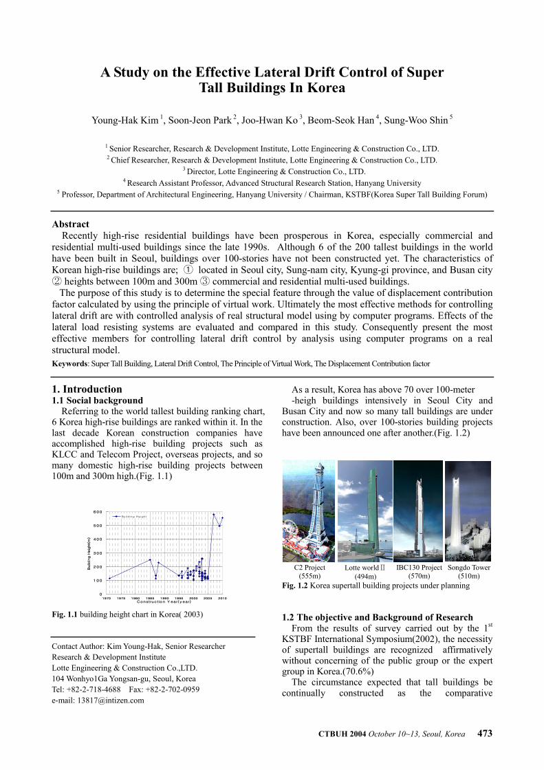
Referring to the world tallest building ranking chart, 6 Korea high-rise buildings are ranked within it. In the last decade Korean construction companies have accomplished high-rise building projects such as KLCC and Telecom Project, overseas projects, and so many domestic high-rise building projects between 100m and 300m high.(Fig. 1.1)
0
100
200
300
400
500
600
1970 1975 1980 1985 1990 1995 2000 2005 2010Construc tio n Y ear( y ear)
Buildin
g H
eig
ht(m
)
Bu i lding Height
Fig. 1.1 building height chart in Korea( 2003)
As a result, Korea has above 70 over 100-meter -heigh buildings intensively in Seoul City and
Busan City and now so many tall buildings are under construction. Also, over 100-stories building projects have been announced one after another.(Fig. 1.2)
C2 Project
(555m) Lotte worldⅡ
(494m) IBC130 Project
(570m) Songdo Tower
(510m) Fig. 1.2 Korea supertall building projects under planning 1.2 The objective and Background of Research
From the results of survey carried out by the 1st KSTBF International Symposium(2002), the necessity of supertall buildings are recognized affirmatively without concerning of the public group or the expert group in Korea.(70.6%)
The circumstance expected that tall buildings be continually constructed as the comparative
Contact Author: Kim Young-Hak, Senior Researcher Research & Development Institute Lotte Engineering & Construction Co.,LTD. 104 Wonhyo1Ga Yongsan-gu, Seoul, Korea Tel: +82-2-718-4688 Fax: +82-2-702-0959 e-mail: [email protected]
474 CTBUH 2004 October 10~13, Seoul, Korea
alternatives of ESSD (Environmentally Sound and Sustainable Development), in other words, the solution of the population problem and a steady demand for supertall building can be expected. Hence, the technologies for constructing supertall building have shifted from the beginning step to technological advanced step in Korea.
Tall buildings are uniquely characterized by requiring that lateral loads be a major design consideration. Two types of loads normally associated with lateral loads are wind and earthquake loads.
In this study, the first analyze the immerging issues of Korean supertall building, the second select actually built or proposed structural systems of tall building, the third analyze structural systems using by computer program, the forth evaluate displacement contribution factor of the structural components such as, beam, column, shearwall, and outrigger which are calculated by using the principle of virtual work.
Therefore, this study is to present that the data that are the structural solution to control the lateral drift effectively. 1.3 The method of Research
In this study, after analyzing the structural model similar to real structural model using computer program(MIDAS Genw. 5.8.1), using values which are calculated one member force of each structural components under the ultimate loading condition and the other member force of each structural components under the unit load(P=1), the displacement of each structural components can be calculated, and then the value to be divided by volume of each components. Finally the impact on the relative size and locations of various structural elements are evaluated. 2. The Emerging Status of Structural System for STB in Korea
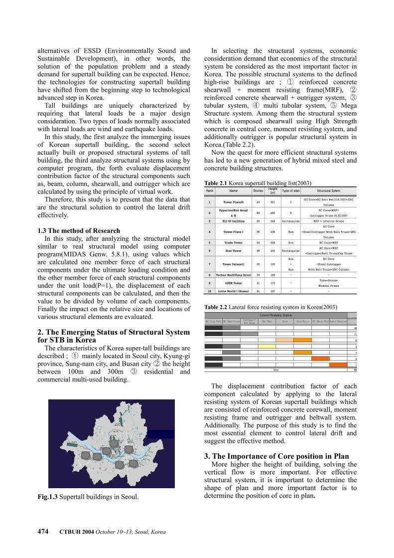
The characteristics of Korea super-tall buildings are described ; ① mainly located in Seoul city, Kyung-gi province, Sung-nam city, and Busan city the height ②between 100m and 300m ③ residential and commercial multi-used building.
Fig.1.3 Supertall buildings in Seoul.
In selecting the structural systems, economic consideration demand that economics of the structural system be considered as the most important factor in Korea. The possible structural systems to the defined high-rise buildings are ; ① reinforced concrete shearwall + moment resisting frame(MRF), ② reinforced concrete shearwall + outrigger system, ③ tubular system, ④ multi tubular system, ⑤ Mega Structure system. Among them the structural system which is composed shearwall using High Strength concrete in central core, moment resisting system, and additionally outrigger is popular structural system in Korea.(Table 2.2).
Now the quest for more efficient structural systems has led to a new generation of hybrid mixed steel and concrete building structures. Table 2.1 Korea supertall building list(2003) Rank Name Stories
Height
(m) Type of plan Structural Sytem
1 Tower PlaceⅢ 69 261 Y RC Core+RC Belt Wall(16,55F)+SRC
Column
2 Hyperion(Mok dong)
A 동 69 256 X
RC Core+MRF+
Outrigger Truss (9,32,50F)
3 KLI 63 building 60 249 Rectangular MRF + interior Brace
4 Tower Place I 66 234 Box
RC Core
+SteelOutrigger With Belt Truss+SRC
Column
5 Trade Tower 54 228 Box RC Core+MRF
6 Star Tower 45 206 Rectangular RC Core+MRF
+Outrigger/Belt Truss/Cap Truss
7 Tower PalaceⅡ 55 195
Box
+
Box
RC Core
+Steel Outrigger
With Belt Truss+SRC Column
8 Techno Mark(Kang Byun) 39 189 - -
8 ASEM Tower 41 170 - Tube+Brace+
Moment Frame
10 Lotte WorldⅠ(Busan) 41 167 - -
Table 2.2 Lateral force resisting system in Korea(2003)
The displacement contribution factor of each component calculated by applying to the lateral resisting system of Korean supertall buildings which are consisted of reinforced concrete corewall, moment resisting frame and outrigger and beltwall system. Additionally. The purpose of this study is to find the most essential element to control lateral drift and suggest the effective method.
3. The Importance of Core position in Plan
More higher the height of building, solving the vertical flow is more important. For effective structural system, it is important to determine the shape of plan and more important factor is to determine the position of core in plan.
RC C ore Wa ll SRC Rig id Fra meO urtrigger/Belt Truss
Fla t Sla b Steel Steel Bra ce RC Shea r Wa ll Super Structure
40
11
5
3
1
2
1
63
qua n tityLa tera l Resisting System
Tota l
CTBUH 2004 October 10~13, Seoul, Korea 475
3.1 The Arrangement of STB in Korea according to Plan Type
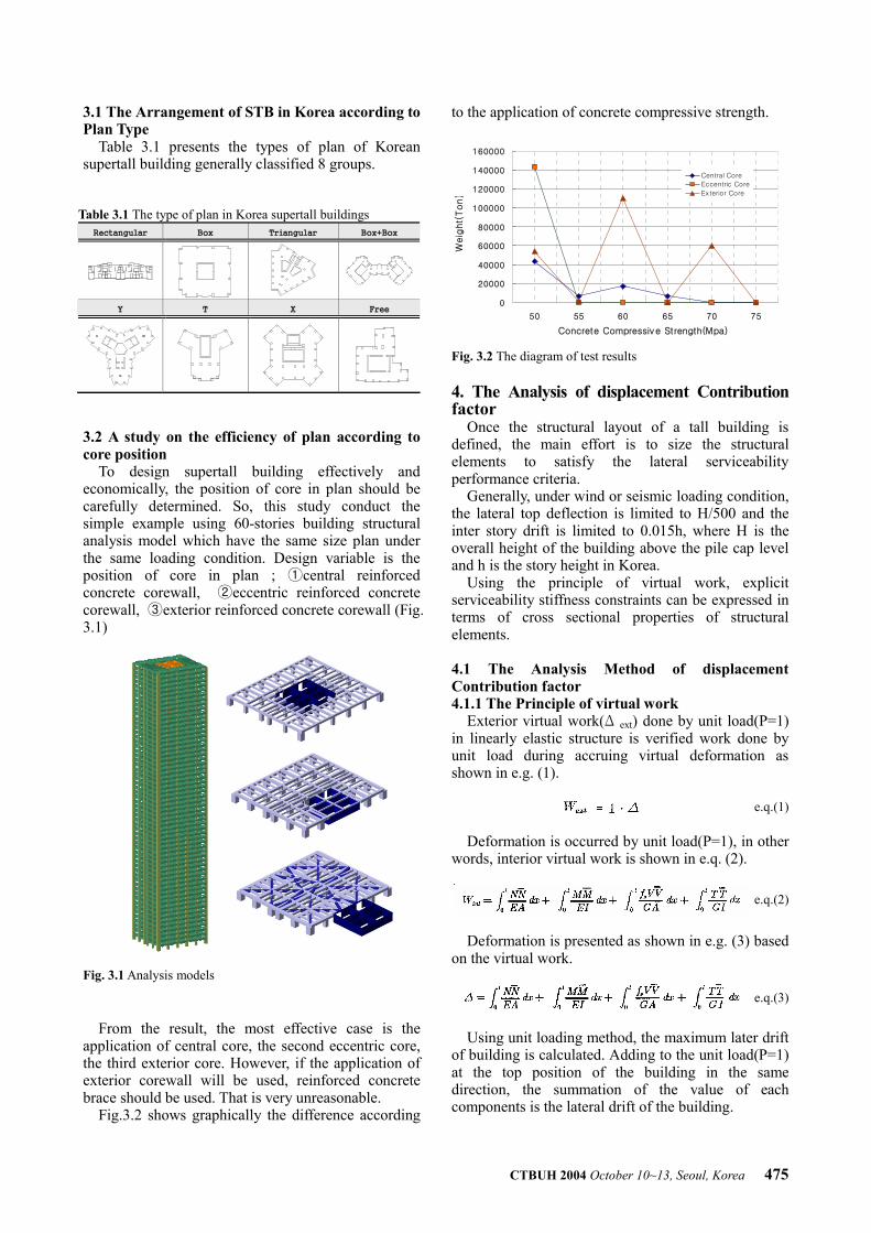
Table 3.1 presents the types of plan of Korean supertall building generally classified 8 groups.
Table 3.1 The type of plan in Korea supertall buildings Rectangular Box Triangular Box+Box
Y T X Free
3.2 A study on the efficiency of plan according to core position
To design supertall building effectively and economically, the position of core in plan should be carefully determined. So, this study conduct the simple example using 60-stories building structural analysis model which have the same size plan under the same loading condition. Design variable is the position of core in plan ; ①central reinforced concrete corewall, ②eccentric reinforced concrete corewall, ③exterior reinforced concrete corewall (Fig. 3.1) Fig. 3.1 Analysis models
From the result, the most effective case is the application of central core, the second eccentric core, the third exterior core. However, if the application of exterior corewall will be used, reinforced concrete brace should be used. That is very unreasonable.
Fig.3.2 shows graphically the difference according
to the application of concrete compressive strength.
Fig. 3.2 The diagram of test results
4. The Analysis of displacement Contribution factor
Once the structural layout of a tall building is defined, the main effort is to size the structural elements to satisfy the lateral serviceability performance criteria.
Generally, under wind or seismic loading condition, the lateral top deflection is limited to H/500 and the inter story drift is limited to 0.015h, where H is the overall height of the building above the pile cap level and h is the story height in Korea.
Using the principle of virtual work, explicit serviceability stiffness constraints can be expressed in terms of cross sectional properties of structural elements. 4.1 The Analysis Method of displacement Contribution factor 4.1.1 The Principle of virtual work
Exterior virtual work(Δ ext) done by unit load(P=1) in linearly elastic structure is verified work done by unit load during accruing virtual deformation as shown in e.g. (1).
e.q.(1)
Deformation is occurred by unit load(P=1), in other words, interior virtual work is shown in e.q. (2).
e.q.(2)
Deformation is presented as shown in e.g. (3) based
on the virtual work.
e.q.(3)
Using unit loading method, the maximum later drift
of building is calculated. Adding to the unit load(P=1) at the top position of the building in the same direction, the summation of the value of each components is the lateral drift of the building.
0
20000
40000
60000
80000
100000
120000
140000
160000
50 55 60 65 70 75
Concrete Compressiv e Strength(Mpa)
Weig
ht(
Ton)
Central Core
Eccentric Core
Exterior Core
476 CTBUH 2004 October 10~13, Seoul, Korea
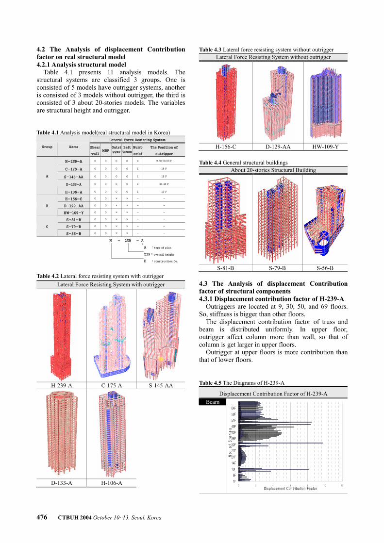
4.2 The Analysis of displacement Contribution factor on real structural model 4.2.1 Analysis structural model
Table 4.1 presents 11 analysis models. The structural systems are classified 3 groups. One is consisted of 5 models have outrigger systems, another is consisted of 3 models without outrigger, the third is consisted of 3 about 20-stories models. The variables are structural height and outrigger. Table 4.1 Analysis model(real structural model in Korea)
Lateral Force Resisting System
Group Name Shear
wall MRF
Outri
gger
Belt
truss
Numb
er(s)
The Position of
outrigger
H-239-A O O O O 4 9,30,50,69 F
C-175-A O O O O 1 19 F
S-145-AA O O O O 1 15 F
D-133-A O O O O 2 23,43 F
A
H-106-A O O O O 1 10 F
H-156-C O O × × - -
D-129-AA O O × × - - B
HW-109-Y O O × × - -
S-81-B O O × × - -
S-79-B O O × × - - C
S-56-B O O × × - -
H - 239 - A
A : type of plan
239 : overall height
H : construction Co.
Table 4.2 Lateral force resisting system with outrigger
Lateral Force Resisting System with outrigger
H-239-A C-175-A S-145-AA
D-133-A H-106-A
Table 4.3 Lateral force resisting system without outrigger Lateral Force Resisting System without outrigger
H-156-C D-129-AA HW-109-Y
Table 4.4 General structural buildings
About 20-stories Structural Building
S-81-B S-79-B S-56-B
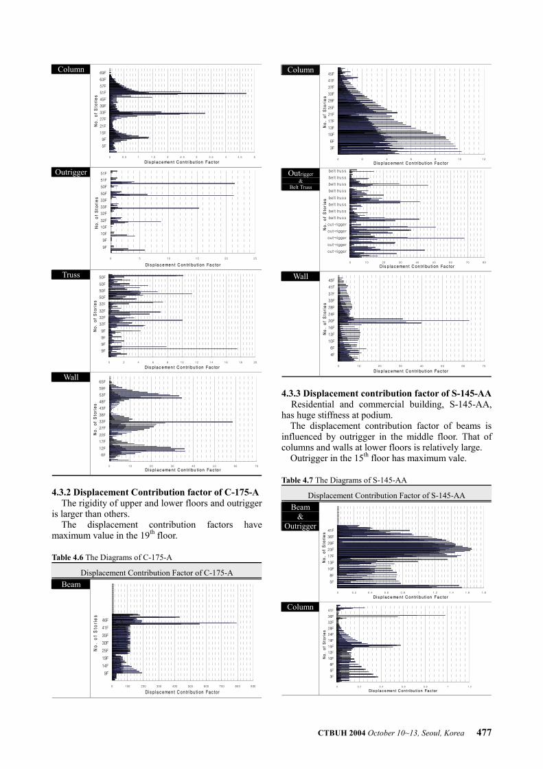
4.3 The Analysis of displacement Contribution factor of structural components 4.3.1 Displacement contribution factor of H-239-A
Outriggers are located at 9, 30, 50, and 69 floors. So, stiffness is bigger than other floors.
The displacement contribution factor of truss and beam is distributed uniformly. In upper floor, outrigger affect column more than wall, so that of column is get larger in upper floors.
Outrigger at upper floors is more contribution than that of lower floors. Table 4.5 The Diagrams of H-239-A
Displacement Contribution Factor of H-239-A Beam
0 2 4 6 8 10 12
1F
6F
10F
14F
21F
27F
32F
36F
42F
49F
51F
58F
64F
No
. o
f S
tori
es
Di s plac eme nt C on tr i bu tion Fac to r
CTBUH 2004 October 10~13, Seoul, Korea 477
Column
0 0.5 1 1.5 2 2.5 3 3.5 4 4.5 5
5F
9F
15F
21F
27F
33F
39F
45F
51F
57F
63F
69F
No
. o
f S
tori
es
D is place me nt C on tr ibu tion Fac tor
Outrigger
0 5 10 15 20 25
9F
9F
10F
10F
32F
32F
33F
33F
50F
50F
51F
51F
No
. o
f S
tori
es
Di s p lacemen t C on tr i bu tion Fac tor
Truss
0 2 4 6 8 10 12 14 16 18 20
9F
9F
9F
9F
32F
32F
32F
32F
50F
50F
50F
50F
No
. o
f S
tori
es
Dis plac emen t C ontr ibu tion Fac to r
Wall
0 10 20 30 40 50 60 70
6F
12F
17F
22F
27F
33F
38F
43F
48F
53F
59F
65F
No
. o
f S
tori
es
Dis p lac emen t C on tr ibu tion Fac tor
4.3.2 Displacement Contribution factor of C-175-A
The rigidity of upper and lower floors and outrigger is larger than others.
The displacement contribution factors have maximum value in the 19th floor. Table 4.6 The Diagrams of C-175-A
Displacement Contribution Factor of C-175-A Beam
0 100 200 300 400 500 600 700 800 900
9F
14F
19F
25F
30F
35F
41F
46F
No
. o
f S
tori
es
Di s placemen t C on tr i bu ti on Fac tor
Column
0 2 4 6 8 10 12
3F
6F
10F
13F
17F
21F
25F
29F
33F
37F
41F
45F
No
. o
f S
tori
es
Di s p lac ement Con tr i bu tion Fac tor
Outrigger&
Belt Truss
0 10 20 30 40 50 60 70 80
out-rigger
out-rigger
out-rigger
out-rigger
out-rigger
belt truss
belt truss
belt truss
belt truss
belt truss
belt truss
belt truss
belt truss
No
. o
f S
tori
es
Di s p lacemen t C on tr i bu tion Fac tor
Wall
0 10 20 30 40 50 60 70
4F
6F
10F
13F
16F
20F
24F
28F
33F
37F
41F
45F
No
. o
f S
tori
es
Di s p lac ement Con tr i bu tion Fac tor
4.3.3 Displacement contribution factor of S-145-AA
Residential and commercial building, S-145-AA, has huge stiffness at podium.
The displacement contribution factor of beams is influenced by outrigger in the middle floor. That of columns and walls at lower floors is relatively large.
Outrigger in the 15th floor has maximum vale. Table 4.7 The Diagrams of S-145-AA
Displacement Contribution Factor of S-145-AA Beam
& Outrigger
0 0.2 0.4 0.6 0.8 1 1.2 1.4 1.6 1.8
5F
8F
10F
13F
17F
23F
29F
36F
41F
No
. o
f S
tori
es
Di s p lace me nt Contr ibu tion Fac tor
Column
0 0.2 0.4 0.6 0.8 1 1.2
3F
5F
8F
10F
12F
15F
19F
24F
28F
32F
36F
41F
No
. o
f S
tori
es
Di s place ment C on tr i bu ti on Fac tor
478 CTBUH 2004 October 10~13, Seoul, Korea
Wall
0 50 100 150 200 250 300 350
3F
6F
9F
12F
15F
19F
23F
26F
30F
34F
38F
42F
No
. o
f S
tori
es
Di s p lace me nt C on tr i bu tion Fac tor
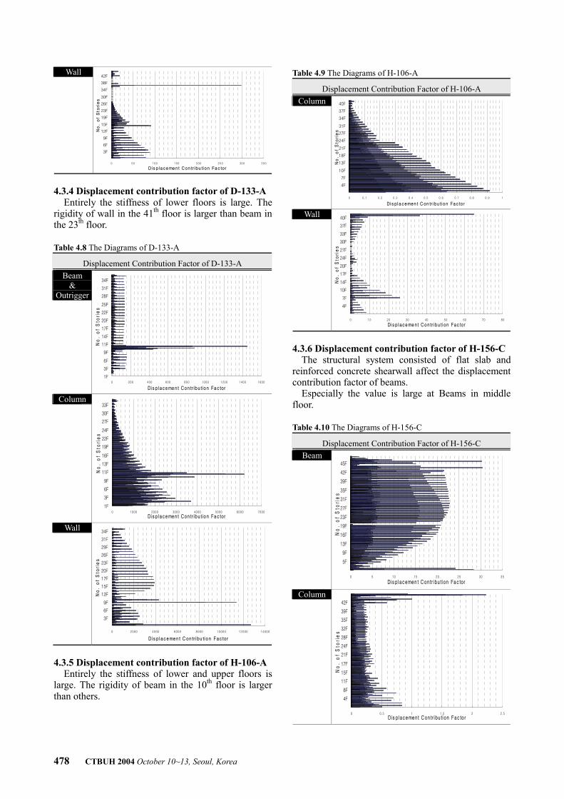
4.3.4 Displacement contribution factor of D-133-A
Entirely the stiffness of lower floors is large. The rigidity of wall in the 41th floor is larger than beam in the 23th floor. Table 4.8 The Diagrams of D-133-A
Displacement Contribution Factor of D-133-A Beam
& Outrigger
0 200 400 600 800 1000 1200 1400 1600
1F
3F
6F
9F
11F
14F
17F
20F
22F
25F
28F
31F
34F
No
. o
f S
tori
es
Di s p lace me nt Contr ibu tion Fac tor
Column
0 1000 2000 3000 4000 5000 6000 7000
1F
3F
6F
9F
11F
13F
16F
19F
22F
24F
27F
30F
33F
No
. o
f S
tori
es
Di s p lace me nt Contr ibu tion Fac tor
Wall
0 2000 4000 6000 8000 10000 12000 14000
3F
6F
9F
12F
15F
17F
20F
23F
26F
29F
31F
34F
No
. o
f S
tori
es
Di s placemen t C on tr ibu tion Fac tor
4.3.5 Displacement contribution factor of H-106-A
Entirely the stiffness of lower and upper floors is large. The rigidity of beam in the 10th floor is larger than others.
Table 4.9 The Diagrams of H-106-A
Displacement Contribution Factor of H-106-A Column
0 0.1 0.2 0.3 0.4 0.5 0.6 0.7 0.8 0.9 1
4F
7F
10F
13F
18F
21F
24F
27F
31F
34F
37F
40F
No
. o
f S
tori
es
Di s placemen t C on tr i bu tion Fac tor
Wall
0 10 20 30 40 50 60 70 80
4F
7F
10F
14F
17F
20F
24F
27F
30F
33F
37F
40F
No
. o
f S
tori
es
Di s p lace me nt Contr ibu tion Fac tor
4.3.6 Displacement contribution factor of H-156-C
The structural system consisted of flat slab and reinforced concrete shearwall affect the displacement contribution factor of beams.
Especially the value is large at Beams in middle floor. Table 4.10 The Diagrams of H-156-C
Displacement Contribution Factor of H-156-C Beam
0 5 10 15 20 25 30 35
5F
9F
13F
16F
19F
23F
27F
31F
35F
39F
42F
45F
No
. o
f S
tori
es
Di s p lacemen t C on tr i bu tion Fac tor
Column
0 0.5 1 1.5 2 2.5
4F
8F
11F
15F
17F
21F
24F
28F
32F
35F
39F
42F
No
. o
f S
tori
es
Dis place ment C ontr ibu tion Fac to r
CTBUH 2004 October 10~13, Seoul, Korea 479
Wall
0 10 20 30 40 50 60 70 80 90 100
4F
8F
12F
16F
20F
24F
28F
32F
36F
40F
44F
48F
No
. o
f S
tori
es
Dis plac emen t C ontr ibu tion Fac to r
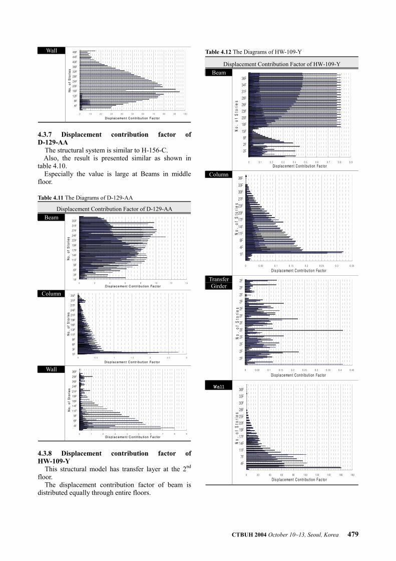
4.3.7 Displacement contribution factor of D-129-AA
The structural system is similar to H-156-C. Also, the result is presented similar as shown in
table 4.10. Especially the value is large at Beams in middle
floor. Table 4.11 The Diagrams of D-129-AA
Displacement Contribution Factor of D-129-AA Beam
0 2 4 6 8 10 12 14
1F
3F
6F
9F
11F
14F
17F
19F
22F
24F
27F
31F
35F
No
. o
f S
tori
es
Di s p lacement C on tr ibu tion Fac tor
Column
0 0.5 1 1.5 2 2.5 3
1F
3F
6F
8F
11F
13F
16F
19F
21F
24F
27F
31F
35F
No
. o
f S
tori
es
Dis p lacemen t Contr ibu tion Fac tor
Wall
0 1 2 3 4 5 6 7 8 9
4F
6F
9F
11F
14F
16F
19F
21F
24F
26F
29F
36F
No
. o
f S
tori
es
Di s p lac ement C ontr ibu tion Fac tor
4.3.8 Displacement contribution factor of HW-109-Y
This structural model has transfer layer at the 2nd floor.
The displacement contribution factor of beam is distributed equally through entire floors.
Table 4.12 The Diagrams of HW-109-Y
Displacement Contribution Factor of HW-109-Y Beam
0 0.1 0.2 0.3 0.4 0.5 0.6 0.7 0.8 0.9
2F
2F
8F
15F
18F
20F
23F
26F
28F
31F
34F
36F
No
. o
f S
tori
es
Di s plac emen t C on tr i bu ti on Fac tor
Column
0 0.05 0.1 0.15 0.2 0.25 0.3 0.35
1F
4F
8F
11F
14F
17F
20F
23F
27F
30F
33F
36F
No
. o
f S
tori
es
Di s p lace men t C ontr ibu tion Fac to r
TransferGirder
0 0.05 0.1 0.15 0.2 0.25 0.3 0.35 0.4 0.45
2F
2F
2F
2F
2F
2F
2F
2F
2F
2F
2F
2F
No
. o
f S
tori
es
Di s p lace men t C ontr ibu tion Fac tor
Wall
0 20 40 60 80 100 120 140 160 180
4F
7F
11F
14F
17F
19F
22F
25F
28F
30F
33F
36F
No
. o
f S
tori
es
Di s plac eme nt C on tr ibu tion Fac to r
480 CTBUH 2004 October 10~13, Seoul, Korea
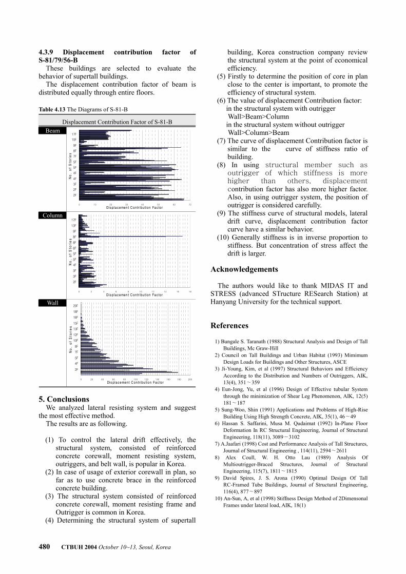
4.3.9 Displacement contribution factor of S-81/79/56-B
These buildings are selected to evaluate the behavior of supertall buildings.
The displacement contribution factor of beam is distributed equally through entire floors. Table 4.13 The Diagrams of S-81-B
Displacement Contribution Factor of S-81-B Beam
0 10 20 30 40 50 60 70
2F
2F
3F
4F
4F
5F
5F
7F
8F
9F
10F
17F
No
. o
f S
tori
es
Di s p lace men t C ontr ibu tion Fac to r
Column
0 2 4 6 8 10 12 14 16 18
2F
3F
3F
4F
5F
5F
6F
8F
8F
9F
13F
17F
No
. o
f S
tori
es
Di s p lace men t C ontr ibu tion Fac to r
Wall
0 20 40 60 80 100 120 140 160 180 200
2F
4F
5F
7F
8F
10F
12F
13F
15F
16F
18F
20F
No
. o
f S
tori
es
Di s placemen t C on tr ibu tion Fac tor
5. Conclusions
We analyzed lateral resisting system and suggest the most effective method.
The results are as following. (1) To control the lateral drift effectively, the
structural system, consisted of reinforced concrete corewall, moment resisting system, outriggers, and belt wall, is popular in Korea.
(2) In case of usage of exterior corewall in plan, so far as to use concrete brace in the reinforced concrete building.
(3) The structural system consisted of reinforced concrete corewall, moment resisting frame and Outrigger is common in Korea.
(4) Determining the structural system of supertall
building, Korea construction company review the structural system at the point of economical efficiency.
(5) Firstly to determine the position of core in plan close to the center is important, to promote the efficiency of structural system.
(6) The value of displacement Contribution factor: in the structural system with outrigger Wall>Beam>Column in the structural system without outrigger Wall>Column>Beam (7) The curve of displacement Contribution factor is
similar to the curve of stiffness ratio of building.
(8) In using structural member such as outrigger of which stiffness is more higher than others, displacement contribution factor has also more higher factor. Also, in using outrigger system, the position of outrigger is considered carefully.
(9) The stiffness curve of structural models, lateral drift curve, displacement contribution factor curve have a similar behavior.
(10) Generally stiffness is in inverse proportion to stiffness. But concentration of stress affect the drift is larger.
Acknowledgements
The authors would like to thank MIDAS IT and
STRESS (advanced STructure RESearch Station) at Hanyang University for the technical support. References
1) Bungale S. Taranath (1988) Structural Analysis and Design of Tall
Buildings, Mc Graw-Hill 2) Council on Tall Buildings and Urban Habitat (1993) Mimimum
Design Loads for Buildings and Other Structures, ASCE 3) Ji-Young, Kim, et al (1997) Structural Behaviors and Efficiency
According to the Distribution and Numbers of Outriggers, AIK, 13(4), 351∼359
4) Eun-Jong, Yu, et al (1996) Design of Effective tubular System through the minimization of Shear Leg Phenomenon, AIK, 12(5) 181∼187
5) Sung-Woo, Shin (1991) Applications and Problems of High-Rise Building Using High Strength Concrete, AIK, 35(1), 46∼49
6) Hassan S. Saffarini, Musa M. Qudaimat (1992) In-Plane Floor Deformation In RC Structural Engineering, Journal of Structural Engineering, 118(11), 3089∼3102
7) A.Jaafari (1998) Cost and Performance Analysis of Tall Structures, Journal of Structural Engineering , 114(11), 2594∼2611
8) Alex Coull, W. H. Otto Lau (1989) Analysis Of Multioutrigger-Braced Structures, Journal of Structural Engineering, 115(7), 1811∼1815
9) David Spires, J. S. Arona (1990) Optimal Design Of Tall RC-Framed Tube Buildings, Journal of Structural Engineering, 116(4), 877∼897
10) An-Sun, A, et al (1998) Stiffness Design Method of 2Dimensonal Frames under lateral load, AIK, 18(1)