Embed Size (px)
Citation preview

Dissertation for Doctor of Philosophy
A study on reinforcement learning based robotintelligence for interaction between bio-insect and
artificial robot
Ji-Hwan Son
School of Mechatronics
Gwangju Institute of Science and Technology
2015

박사학위논문
바이오곤충과로봇의상호작용을위한강화학습
기반의로봇지능연구
손 지환
기전공학부
광주과학기술원
2015
PHD/ME20102044
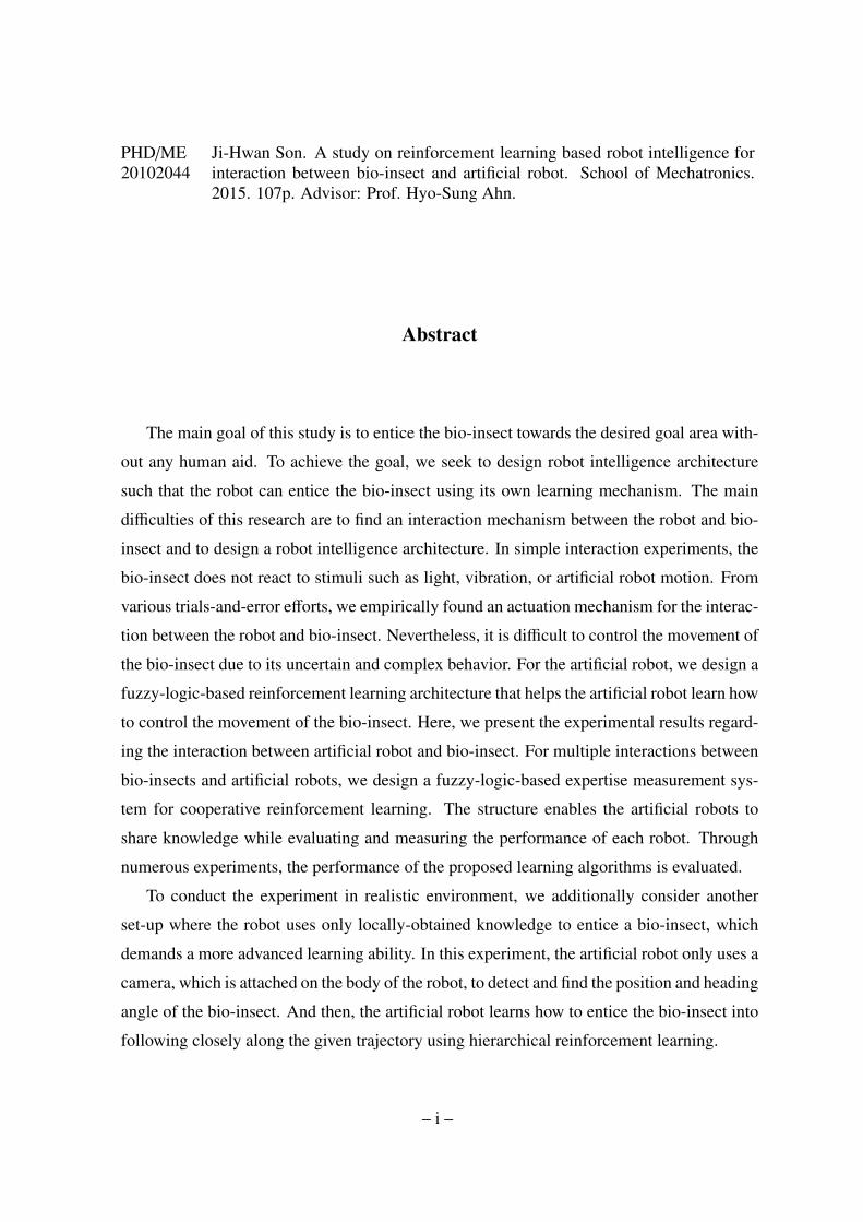
Ji-Hwan Son. A study on reinforcement learning based robot intelligence forinteraction between bio-insect and artificial robot. School of Mechatronics.2015. 107p. Advisor: Prof. Hyo-Sung Ahn.
Abstract
The main goal of this study is to entice the bio-insect towards the desired goal area with-
out any human aid. To achieve the goal, we seek to design robot intelligence architecture
such that the robot can entice the bio-insect using its own learning mechanism. The main
difficulties of this research are to find an interaction mechanism between the robot and bio-
insect and to design a robot intelligence architecture. In simple interaction experiments, the
bio-insect does not react to stimuli such as light, vibration, or artificial robot motion. From
various trials-and-error efforts, we empirically found an actuation mechanism for the interac-
tion between the robot and bio-insect. Nevertheless, it is difficult to control the movement of
the bio-insect due to its uncertain and complex behavior. For the artificial robot, we design a
fuzzy-logic-based reinforcement learning architecture that helps the artificial robot learn how
to control the movement of the bio-insect. Here, we present the experimental results regard-
ing the interaction between artificial robot and bio-insect. For multiple interactions between
bio-insects and artificial robots, we design a fuzzy-logic-based expertise measurement sys-
tem for cooperative reinforcement learning. The structure enables the artificial robots to
share knowledge while evaluating and measuring the performance of each robot. Through
numerous experiments, the performance of the proposed learning algorithms is evaluated.
To conduct the experiment in realistic environment, we additionally consider another
set-up where the robot uses only locally-obtained knowledge to entice a bio-insect, which
demands a more advanced learning ability. In this experiment, the artificial robot only uses a
camera, which is attached on the body of the robot, to detect and find the position and heading
angle of the bio-insect. And then, the artificial robot learns how to entice the bio-insect into
following closely along the given trajectory using hierarchical reinforcement learning.
– i –

c©2015
Ji-Hwan Son
ALL RIGHTS RESERVED
– ii –

PHD/ME20102044
손지환. 바이오곤충과로봇의상호작용을위한강화학습기반의로봇지능연구. 기전공학부. 2015. 107p. 지도교수: 안효성.
국문요약
이연구의중점목표는인간의도움없이실제살아있는바이오-곤충을로봇스
스로의학습과정을통하여특정골위치또는주어진궤도로유인해내는것이다. 이
목표를성취하기위해서이연구에서는로봇이곤충을유인해내는학습능력을갖출
수 있도록 로봇 지능 구조를 설계하고자 한다. 우리가 선정한 바이오 곤충을 대상으
로간단한상호작용실험을한결과바이오곤충은빛,진동,로봇의움직임에대해서
별다른반응을보이지않았다. 다양한시행착오를통해서우리는곤충과로봇간의상
호작용을할수있는메커니즘을찾아내었다. 그럼에도불구하고바이오곤충은로봇
의상호작용에대해서곤충의움직임은무작위적이고복잡한움직임을보였으며,이
러한행동으로인해서곤충의움직임을제어하는것에어려움이있었다. 앞서설명한
것과같이무작위적이고복잡한움직임을보이는곤충에대해서로봇스스로상호작
용과정을통해서곤충의움직임을제어하기위해서이논문에서는퍼지로직기반의
강화학습구조를설계하였다. 해당구조를바탕으로한마리의살아있는곤충과한개
의로봇간의상호작용실험을진행하였으며,해당학습구조를이용하여로봇스스로
곤충을유인할수있음을확인하였다. 또한한마리의곤충과다개체로봇간의상호작
용연구로확장해나가기위해서이연구에서는퍼지로직기반의전문성평가시스템
을 이용한 협동 강화학습 구조를 제안하였다. 이 구조는 각 로봇들이 실험하면서 얻
은성능에대한다양한평가표를기반으로퍼지로직을이용하여서로의지식을효율
적으로공유하도록설계하였다. 추가실험을통해서해당학습알고리즘을바탕으로
실제실험을통하여해당알고리즘의성능을평가하였다. 로봇이실제환경에서직접
곤충을 인지하고 상호작용하기 위해서는 로봇 스스로 곤충을 인지하고 해당 정보를
토대로학습및제어능력이요구된다. 추가적인하드웨어설계및계층구조의강화
학습법을적용한이실험에서는로봇에부착된카메라를이용하여로봇스스로곤충
을찾고인지하며,인지된정보와로봇간의상호작용에의해얻어지는결과를통해서
로봇스스로곤충을주어진궤도를지속적으로움직이도록만들었다.
– iii –

c©2015
손 지환
ALL RIGHTS RESERVED
– iv –
Contents
Abstract (English) i
Abstract (Korean) iii
List of Tables viii
List of Figures ix
1 Introduction 1
1.1 Background . . . . . . . . . . . . . . . . . . . . . . . . . . . . . . . . . . 1
1.2 Motivation and goal of the bio-insect and artificial robot interaction . . . . 2
1.3 Literature review . . . . . . . . . . . . . . . . . . . . . . . . . . . . . . . 5
1.3.1 Interaction between bio-insect and artificial robot . . . . . . . . . . 5
1.3.2 Cooperative reinforcement learning . . . . . . . . . . . . . . . . . 6
1.3.3 Area of expertise . . . . . . . . . . . . . . . . . . . . . . . . . . . 7
1.4 Outline of the thesis . . . . . . . . . . . . . . . . . . . . . . . . . . . . . . 8
2 Preliminaries 10
2.1 Reinforcement learning . . . . . . . . . . . . . . . . . . . . . . . . . . . . 10
2.2 Fuzzy logic . . . . . . . . . . . . . . . . . . . . . . . . . . . . . . . . . . 12
3 Interaction mechanism between bio-insect and artificial robot 16
3.1 Introduction . . . . . . . . . . . . . . . . . . . . . . . . . . . . . . . . . . 16
3.1.1 Platform setup for verifying interaction mechanism . . . . . . . . 16
– v –
3.1.2 Experimental setup for verifying interaction mechanism . . . . . . 20
3.1.3 Experimental results . . . . . . . . . . . . . . . . . . . . . . . . . 23
3.2 Conclusion . . . . . . . . . . . . . . . . . . . . . . . . . . . . . . . . . . 24
4 Fuzzy-logic-based reinforcement learning 25
4.1 Introduction . . . . . . . . . . . . . . . . . . . . . . . . . . . . . . . . . . 25
4.2 Fuzzy logic-based reinforcement learning . . . . . . . . . . . . . . . . . . 25
4.2.1 Design of fuzzy logic-based reinforcement learning . . . . . . . . . 25
4.3 Experimental results . . . . . . . . . . . . . . . . . . . . . . . . . . . . . 32
4.4 Conclusion . . . . . . . . . . . . . . . . . . . . . . . . . . . . . . . . . . 36
5 Fuzzy-logic-based expertise measurement system for cooperative reinforcement
learning 49
5.1 Introduction . . . . . . . . . . . . . . . . . . . . . . . . . . . . . . . . . . 49
5.2 Cooperative reinforcement learning based on a fuzzy logic-based expertise
measurement system . . . . . . . . . . . . . . . . . . . . . . . . . . . . . 50
5.2.1 Fuzzy logic-based cooperative reinforcement learning . . . . . . . 50
5.2.2 A robot . . . . . . . . . . . . . . . . . . . . . . . . . . . . . . . . 51
5.2.3 Expertise measurement . . . . . . . . . . . . . . . . . . . . . . . . 55
5.2.4 Expertise measurement system . . . . . . . . . . . . . . . . . . . . 56
5.2.5 Comments on reinforcement learning approaches . . . . . . . . . . 58
5.3 Experiment . . . . . . . . . . . . . . . . . . . . . . . . . . . . . . . . . . 61
5.3.1 Experimental setup . . . . . . . . . . . . . . . . . . . . . . . . . . 61
– vi –

5.3.2 Experimental results . . . . . . . . . . . . . . . . . . . . . . . . . 64
5.4 Discussions on experimental results . . . . . . . . . . . . . . . . . . . . . 66
5.5 Conclusion . . . . . . . . . . . . . . . . . . . . . . . . . . . . . . . . . . 67
6 Hierarchical reinforcement learning based interaction between bio-insect and
artificial robot 82
6.1 Introduction . . . . . . . . . . . . . . . . . . . . . . . . . . . . . . . . . . 82
6.2 Methodologies . . . . . . . . . . . . . . . . . . . . . . . . . . . . . . . . 83
6.3 Experiment . . . . . . . . . . . . . . . . . . . . . . . . . . . . . . . . . . 85
6.4 Results . . . . . . . . . . . . . . . . . . . . . . . . . . . . . . . . . . . . . 89
6.5 Conclusion . . . . . . . . . . . . . . . . . . . . . . . . . . . . . . . . . . 91
7 Conclusion 97
– vii –

List of Tables
3.1 Experimental results of suggested interaction mechanism . . . . . . . . . . 23
4.1 25 Fuzzy rules . . . . . . . . . . . . . . . . . . . . . . . . . . . . . . . . 31
4.2 Summary of experimental results . . . . . . . . . . . . . . . . . . . . . . . 36
4.3 Detailed experimental results for Exp. 1 . . . . . . . . . . . . . . . . . . . 44
4.4 Detailed experimental results for Exp. 2 . . . . . . . . . . . . . . . . . . . 45
5.1 25 Fuzzy rules . . . . . . . . . . . . . . . . . . . . . . . . . . . . . . . . . 62
5.2 27 Fuzzy rules for expertise measurement system . . . . . . . . . . . . . . 72
5.3 Summary of experimental results . . . . . . . . . . . . . . . . . . . . . . . 75
5.4 Detailed experimental results for experiment A . . . . . . . . . . . . . . . 80
5.5 Detailed experimental results for experiment B . . . . . . . . . . . . . . . 81
6.1 Detailed experimental results . . . . . . . . . . . . . . . . . . . . . . . . . 90
– viii –

List of Figures
1.1 Flowchart of BRIDS composed of the distributed decision, distributed con-
trol, and distributed sensing. Subsystems are connected in a feedback loop
manner. . . . . . . . . . . . . . . . . . . . . . . . . . . . . . . . . . . . . 3
1.2 Structure of BRIDS: It shows how to relate the individual subsystems. The
first step is to construct distributed sensing, distributed decision and dis-
tributed control systems. Then, we construct a closed-system based on a
feedback loop for learning and the exchange of knowledge for sharing infor-
mation. . . . . . . . . . . . . . . . . . . . . . . . . . . . . . . . . . . . . 4
2.1 Several types of membership functions in fuzzy logic: (a) - l-membership
function, (b) - triangular membership function and (c) - r-membership function 14
3.1 (a) - The stag beetles (female(left) and male(right)) (b) - advanced experi-
ment using dual fan motors, (c) - different temperature of air, (d) - different
odor sources . . . . . . . . . . . . . . . . . . . . . . . . . . . . . . . . . . 18
3.2 (a) - The proposed structure of spreading an odor source with a robot using
two air-pump motors to produce airflow and one plastic bottle containing an
odor source composed of sawdust taken from the habitat of the bio-insect.
(b) - robot agent . . . . . . . . . . . . . . . . . . . . . . . . . . . . . . . 20
3.3 Diagram of our designed platform of experiment . . . . . . . . . . . . . . 21
3.4 Hardware platform . . . . . . . . . . . . . . . . . . . . . . . . . . . . . . 22
– ix –
4.1 (a) - Designed state for recognizing current state of location and (b)- photo-
graph of experimental platform . . . . . . . . . . . . . . . . . . . . . . . . 27
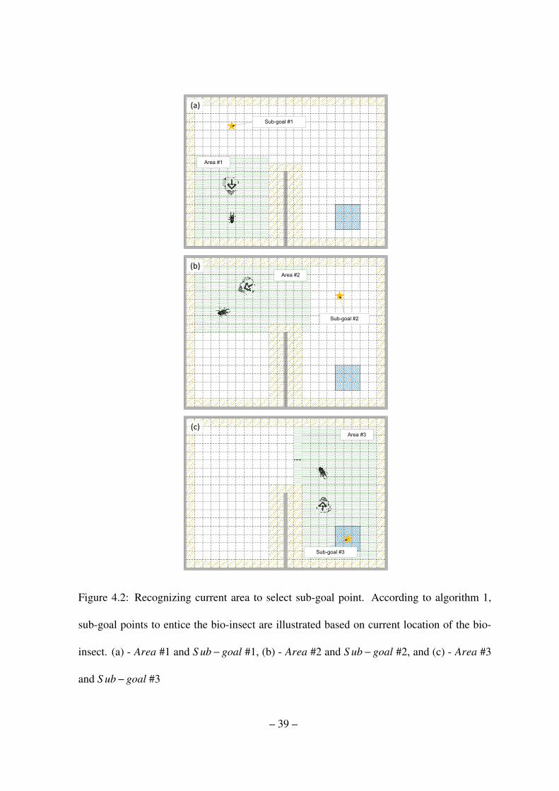
4.2 Recognizing current area to select sub-goal point. According to algorithm
1, sub-goal points to entice the bio-insect are illustrated based on current
location of the bio-insect. (a) - Area #1 and S ub−goal #1, (b) - Area #2 and
S ub−goal #2, and (c) - Area #3 and S ub−goal #3 . . . . . . . . . . . . . 39
4.3 Designed state for recognizing current state - in this case, the state of the
heading angle of the bio-insect is (2), and the state of the goal direction for
the bio-insect is (4). . . . . . . . . . . . . . . . . . . . . . . . . . . . . . . 40
4.4 Architecture of fuzzy logic-based reinforcement learning . . . . . . . . . . 41
4.5 Fuzzy sets (a) - distance variation (∆dt) as an input, (b) - distance variation
(∆et) as an input and (c) - output fuzzy sets . . . . . . . . . . . . . . . . . 42
4.6 Flow chart of learning mechanism of fuzzy-logic-based reinforcement learning 43
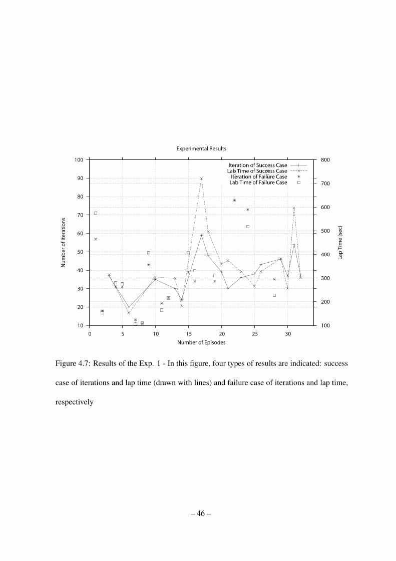
4.7 Results of the Exp. 1 - In this figure, four types of results are indicated:
success case of iterations and lap time (drawn with lines) and failure case of
iterations and lap time, respectively . . . . . . . . . . . . . . . . . . . . . 46
4.8 Results of the Exp. 2 - In this figure, four types of results are indicated:
success case of iterations and lap time (drawn with lines) and failure case of
iterations and lap time, respectively . . . . . . . . . . . . . . . . . . . . . 47
– x –
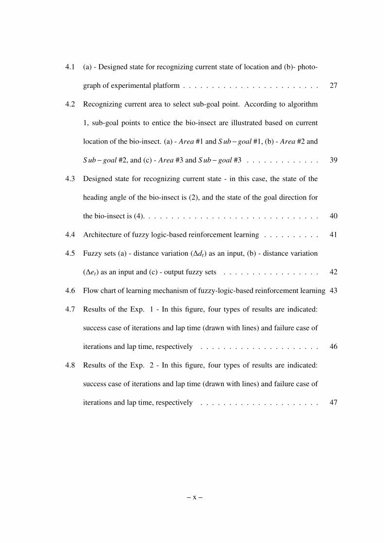
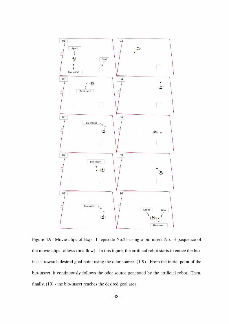
4.9 Movie clips of Exp. 1- episode No.25 using a bio-insect No. 3 (sequence of
the movie clips follows time flow) - In this figure, the artificial robot starts to
entice the bio-insect towards desired goal point using the odor source. (1-9)
- From the initial point of the bio-insect, it continuously follows the odor
source generated by the artificial robot. Then, finally, (10) - the bio-insect
reaches the desired goal area. . . . . . . . . . . . . . . . . . . . . . . . . 48
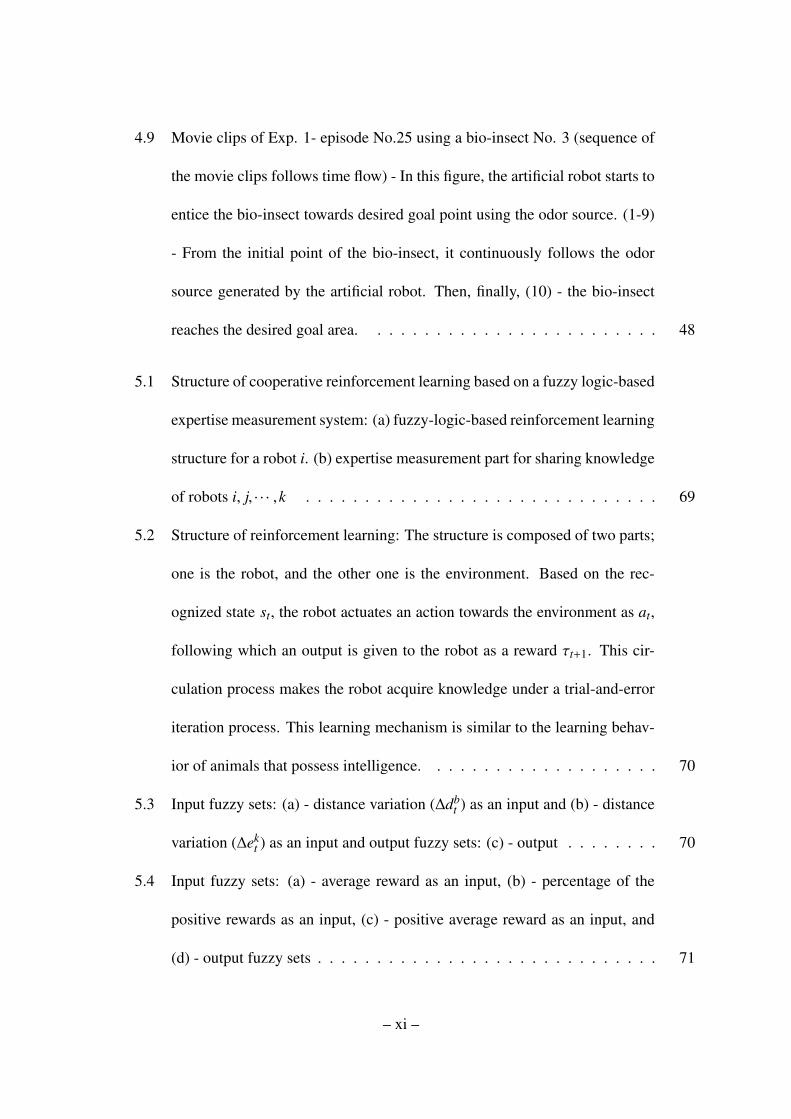
5.1 Structure of cooperative reinforcement learning based on a fuzzy logic-based
expertise measurement system: (a) fuzzy-logic-based reinforcement learning
structure for a robot i. (b) expertise measurement part for sharing knowledge
of robots i, j, · · · ,k . . . . . . . . . . . . . . . . . . . . . . . . . . . . . . 69
5.2 Structure of reinforcement learning: The structure is composed of two parts;
one is the robot, and the other one is the environment. Based on the rec-
ognized state st, the robot actuates an action towards the environment as at,
following which an output is given to the robot as a reward τt+1. This cir-
culation process makes the robot acquire knowledge under a trial-and-error
iteration process. This learning mechanism is similar to the learning behav-
ior of animals that possess intelligence. . . . . . . . . . . . . . . . . . . . 70
5.3 Input fuzzy sets: (a) - distance variation (∆dbt ) as an input and (b) - distance
variation (∆ekt ) as an input and output fuzzy sets: (c) - output . . . . . . . . 70
5.4 Input fuzzy sets: (a) - average reward as an input, (b) - percentage of the
positive rewards as an input, (c) - positive average reward as an input, and
(d) - output fuzzy sets . . . . . . . . . . . . . . . . . . . . . . . . . . . . . 71
– xi –
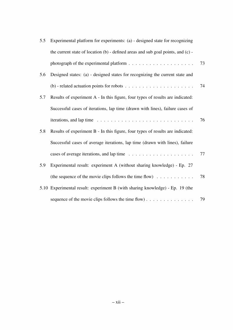
5.5 Experimental platform for experiments: (a) - designed state for recognizing
the current state of location (b) - defined areas and sub goal points, and (c) -
photograph of the experimental platform . . . . . . . . . . . . . . . . . . . 73
5.6 Designed states: (a) - designed states for recognizing the current state and
(b) - related actuation points for robots . . . . . . . . . . . . . . . . . . . . 74
5.7 Results of experiment A - In this figure, four types of results are indicated:
Successful cases of iterations, lap time (drawn with lines), failure cases of
iterations, and lap time . . . . . . . . . . . . . . . . . . . . . . . . . . . . 76
5.8 Results of experiment B - In this figure, four types of results are indicated:
Successful cases of average iterations, lap time (drawn with lines), failure
cases of average iterations, and lap time . . . . . . . . . . . . . . . . . . . 77
5.9 Experimental result: experiment A (without sharing knowledge) - Ep. 27
(the sequence of the movie clips follows the time flow) . . . . . . . . . . . 78
5.10 Experimental result: experiment B (with sharing knowledge) - Ep. 19 (the
sequence of the movie clips follows the time flow) . . . . . . . . . . . . . . 79
– xii –
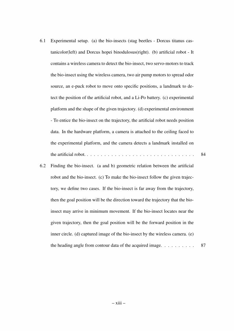
6.1 Experimental setup. (a) the bio-insects (stag beetles - Dorcus titanus cas-
tanicolor(left) and Dorcus hopei binodulosus(right). (b) artificial robot - It
contains a wireless camera to detect the bio-insect, two servo-motors to track
the bio-insect using the wireless camera, two air pump motors to spread odor
source, an e-puck robot to move onto specific positions, a landmark to de-
tect the position of the artificial robot, and a Li-Po battery. (c) experimental
platform and the shape of the given trajectory. (d) experimental environment
- To entice the bio-insect on the trajectory, the artificial robot needs position
data. In the hardware platform, a camera is attached to the ceiling faced to
the experimental platform, and the camera detects a landmark installed on
the artificial robot. . . . . . . . . . . . . . . . . . . . . . . . . . . . . . . . 84
6.2 Finding the bio-insect. (a and b) geometric relation between the artificial
robot and the bio-insect. (c) To make the bio-insect follow the given trajec-
tory, we define two cases. If the bio-insect is far away from the trajectory,
then the goal position will be the direction toward the trajectory that the bio-
insect may arrive in minimum movement. If the bio-insect locates near the
given trajectory, then the goal position will be the forward position in the
inner circle. (d) captured image of the bio-insect by the wireless camera. (e)
the heading angle from contour data of the acquired image. . . . . . . . . . 87
– xiii –

6.3 States. (a) - To entice the bio-insect, we define five specific motions of the
bio-insect as follows: go ahead, turn left and go, rotate right, turn left and go,
and rotate left. In this experiment, the artificial robot learns which motion is
necessary to make the bio-insect move towards the found goal position using
the behavior state. (b) - To make the bio-insect act as the chosen motion
on the behavior state, the artificial robot finds a suitable action position to
spread odor source near the bio-insect. (c) the set of behavior states - There
are seven angular sections between the heading angle of the bio-insect and
goal direction; but at the central angular section, we further consider two
cases according to the distance ranges between goal and the bio-insect. (d)
the set of action states - The set of action states is a combination of seven
angular sections between heading angle of the bio-insect and artificial robot
direction and three distance ranges between the bio-insect and the artificial
robot. . . . . . . . . . . . . . . . . . . . . . . . . . . . . . . . . . . . . . 94
6.4 Experimental results - transition of the moving path of the bio-insect (blue
dots) as iterations increase. . . . . . . . . . . . . . . . . . . . . . . . . . . 95
6.5 Experimental results. (a) sum of total rewards of each states has increased
with iteration steps, (b) captured trail image of the bio-insect every 30sec
from 698 to 747 iterations including start and end position of the bio-insect. 96
– xiv –

Chapter 1
Introduction
1.1 Background
Currently, the need for a mobile robot arises from the demand for convenience of life
and the replacement of humans in completing perilous tasks. Also, due to the many possi-
bilities of use of a mobile robot, its development holds great prospects. However, despite its
necessity and significance, speed of the mobile robot development has been stagnant due to
the difficulty in creating robot intelligence. There has still been no dominant work in robot
intelligence due to the difficulty of creating artificial intelligence for robots (Hopgood, 2003;
Merrick, 2010). This is especially true in our daily environment context, which involves
complex and unpredictable elements. The project, called BRIDS (Bio-insect and artificial
Robot Intelligence based on Distributed Systems) (Ji-Hwan Son, 2014; Son & Ahn, Oct.
2008), seeks to study the interaction between bio-insects and artificial robots to establish a
new architectural framework for improving the intelligence of robots. In this project, we use
a living bio-insect which has its own intelligence to survive in nature. Because of the its own
intelligence, behavior of the bio-insect also involves complex and unpredictable elements.
Therefore, studying interaction between a living insect from nature and artificial robot will
provide an idea how to enhance the intelligence of robots. In this study, as a specific task for
the interaction between a bio-insect and artificial robot, we would like to entice bio-insects
– 1 –

towards desired goal areas using artificial robots without any human aid.
It is not an easy task to define the dynamics of such a system because the motion of living
bio-insects also features uncertain and complex behavior. Thus, understanding, predicting,
and controlling the movement of a bio-insect are the main issues that have to be addressed
in this research. Thus, the potential contribution of this research lies in the field of robot
intelligence; it establishes a new learning framework for an intelligent robot, which consti-
tutes a type of coordination for a community composed of bio-insects and artificial robots.
The research on bio-insect and artificial robot interaction will provide a fundamental theo-
retical framework for human and robot interactions. The applications include service robots,
cleaning robots, intelligence monitoring systems, intelligent buildings and ITS. This research
studies the control of model-free bio-systems; thus, it could be also used for a control of
complex systems, such as metropolitan transportation control and environmental monitor-
ing, which cannot be readily modeled in advance. The result may also be used to attract and
expel harmful insects, such as cockroaches, via interaction and intra-communication.
1.2 Motivation and goal of the bio-insect and artificial robot interaction
This research seeks to study a bio-insect and artificial robot interaction to establish a new
architectural framework for improving the intelligence of mobile robots. One of the main
research goals is to drive or entice a bio-insect through the coordination of a group of mobile
robots towards a desired point. The research includes the establishment of hardware/software
for the bio-insect and artificial robot interaction and the synthesis of distributed sensing, dis-
tributed decision-making, and distributed control systems for building a network composed
– 2 –
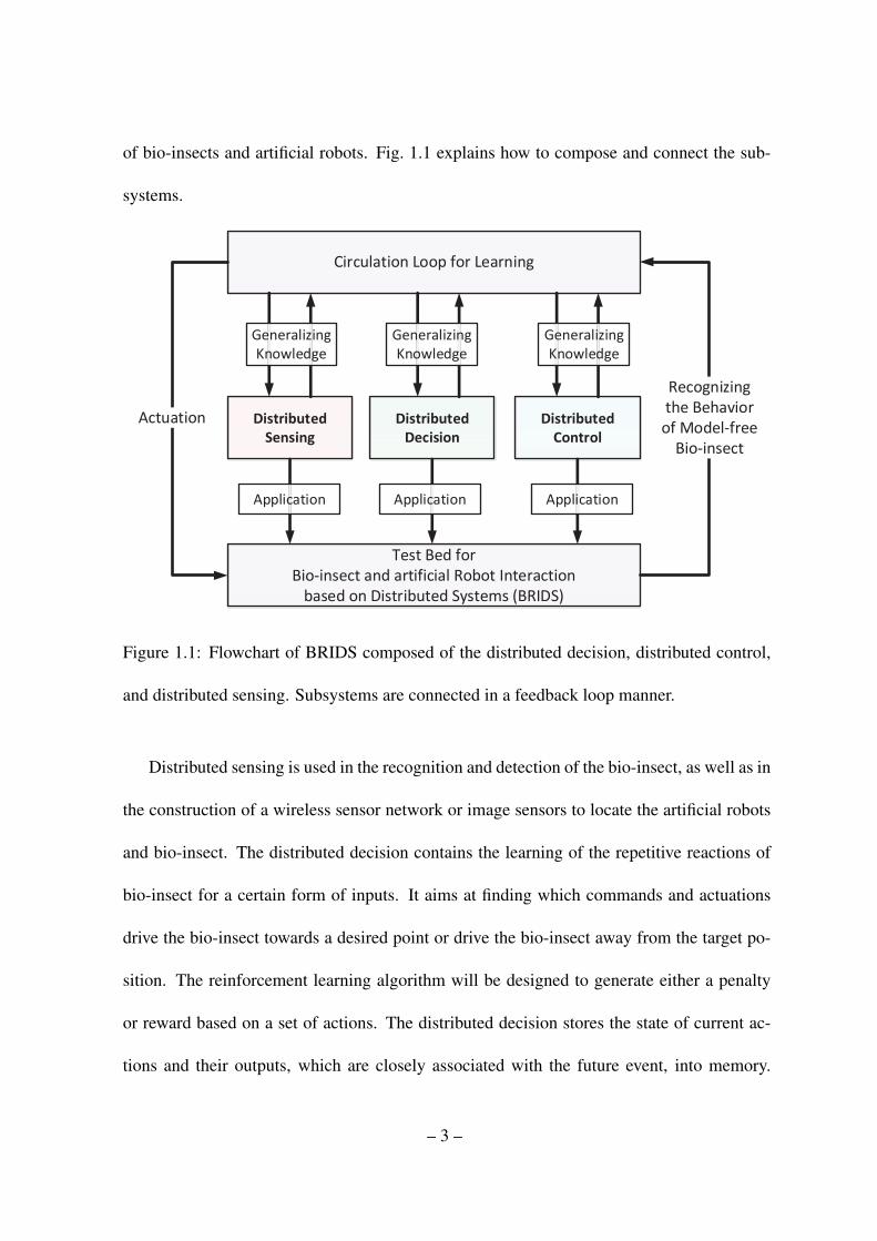
of bio-insects and artificial robots. Fig. 1.1 explains how to compose and connect the sub-
systems.
Test Bed for
Bio-insect and artificial Robot Interaction
based on Distributed Systems (BRIDS)
Circulation Loop for Learning
Actuation
Recognizing
the Behavior
of Model-free
Bio-insect
Generalizing
Knowledge
Application
Generalizing
Knowledge
Application
Generalizing
Knowledge
Application
Figure 1.1: Flowchart of BRIDS composed of the distributed decision, distributed control,
and distributed sensing. Subsystems are connected in a feedback loop manner.
Distributed sensing is used in the recognition and detection of the bio-insect, as well as in
the construction of a wireless sensor network or image sensors to locate the artificial robots
and bio-insect. The distributed decision contains the learning of the repetitive reactions of
bio-insect for a certain form of inputs. It aims at finding which commands and actuations
drive the bio-insect towards a desired point or drive the bio-insect away from the target po-
sition. The reinforcement learning algorithm will be designed to generate either a penalty
or reward based on a set of actions. The distributed decision stores the state of current ac-
tions and their outputs, which are closely associated with the future event, into memory.
– 3 –

Then, it selects commands and outcomes of past actions for the current closed-loop learning.
Thus, the synthesis of the recursive learning algorithm based on the storage and selection
procedure along with the learning will be main point of interest in the distributed decision.
The distributed control includes the control and deployment of the multiple-mobile robots
via coordination, as well as the design of the optimally distributed-control algorithm for the
coordination. It learns how the bio-insect reacts based on the relative speed, position, and
orientation between the multiple-mobile robots and the bio-insect. Thus, the ultimate goal
of this research is to establish a new theoretical framework for robot learning via a recur-
sive sequential procedure of the distributed sensing, decision and control systems. Fig. 1.2
illustrates the structure of the BRIDS.
Test Bed for Bio-insect and artificial Robot
Interaction based on Distributed Systems
(BRIDS)
Figure 1.2: Structure of BRIDS: It shows how to relate the individual subsystems. The first
step is to construct distributed sensing, distributed decision and distributed control systems.
Then, we construct a closed-system based on a feedback loop for learning and the exchange
of knowledge for sharing information.
– 4 –
1.3 Literature review
In this section, we introduce related studies of this research.
1.3.1 Interaction between bio-insect and artificial robot
The interaction between an artificial robot and insect or animal has been studied by var-
ious researchers, and it can be divided into two classes. The first class is physical contact-
based interaction. Installing electrodes into the nervous system and controlling the motion of
insects have been conducted using electric stimuli to a moth (A. Bozkurt, 2009; W. M. Tsang,
2010), a beetle (H. Sato, 2009) and a cockroach (R. Holzer, 1997). Due to the physical con-
tact, the motion of the insects is remotely controlled as desired. The second class is indirect
stimuli-based interaction. In this case, the robots rely on indirect stimuli. For example, the
robot tries to interact with a moth using sex pheromone sources (Y. Kuwana, 1999); a group
of mobile robots influences on a group of cockroaches using the pheromone source (J. Hal-
loy, 2007); and a robot, which contains substances of cricket, tries to interact with a living
cricket (K. Kawabata, 2013). Movement of a mobile robot can also be achieved by an in-
teraction; a mobile robot drags a flock of ducks towards specific goal position (R. Vaughan,
2000) and reduces an anxiety of chickens (Bohlen, 1999) by using a moving algorithm. Spe-
cific locomotion behaviors have been found effective in socializing with fishes (S. Marras,
2012) and in interacting with rats (Q. Shi, 2013). A visual stimuli controls the flight direction
of beetle with LEDs attached on its head (H. Sato, 2008) and it also controls the movement
of turtle (S. Lee, 2013). As mentioned above, various experiments have been conducted,
and diverse attempts on finding new interaction mechanism have been tried. However, the
– 5 –
interaction mechanism still depends on programmed commands or operated by human; thus,
the interaction between the artificial robot and living things, such as insect or animal, based
on intelligent decision and learning behavior has not been studied.
1.3.2 Cooperative reinforcement learning
Note that we use the term “cooperative learning” to represent a learning by sharing data
among multiple autonomous robots. When a robot is faced with given commands for which
the robot lacks a sufficient knowledge base and is required to act alone, the robot may not
be successful in implementing the commands. Or the robot takes a long time to complete
the task. However, if there are several other robots and each of the robots possesses their
own specialized knowledge about the task, then the given commands can be more readily
completed by mutual cooperation. Moreover, when the robots learn knowledge from trials
and errors, some of the robots may have more specialized knowledge than the others, as seen
in human society. If the robots have the ability to share knowledge, then the performance of
the robots would be enhanced. For these reasons, cooperative learning has recently received
a lot of attention due to the various benefits it provides. In Tan (1993), it was explained why
cooperative learning is more attractive compared with independent robot case using multi-
robot based reinforcement learning; and in Littman (1994), they consider two types of robots
that try to complete their opposed goals. Using opposite goals, one robot tries to maximize
its own reward while another robot tries to minimize its own reward. In Tangamchit et al.
(2002), they adopt an average reward-based learning mechanism under different action levels
and task levels. Each level is composed of a hierarchical structure, and the action level per-
– 6 –

forms a given task under the overall current task. Similarly, (Erus & Polat, 2007) introduces
a hierarchical reinforcement learning structure. One of levels tries to learn how to select
a target and the corresponding action. Another level focuses on updating Q-tables, which
contain purposes and learning mechanisms. In Wang & de Silva (2006), they present a team
Q-learning algorithm composed of parallel Q-tables related to several points of view to max-
imize the common goal and in Wang & de Silva (2008), an integrated sequential Q-learning
using a genetic algorithm was presented. Using a fitness function, they evaluate the current
performance and try to find a better performance under selection, crossover, and mutation
processes. In Kok & Vlassis (2006), they introduce sparse cooperative Q-learning, which
has two types of update methods, such as robot-base update and edge-base update, based on
the structure and coordination graph. In our literature survey, we also found various coop-
erative reinforcement learning methods in several survey studies (Courses & Surveys, 2008;
Panait & Luke, 2005); related studies mostly use game theory based on Nash equilibrium or
the zero-sum game in their hierarchical structures.
1.3.3 Area of expertise
In the field of cooperative reinforcement learning, the area of expertise (AOE) concept
was recently proposed in Araabi et al. (2007), where the framework evaluates the perfor-
mance of each robot from several points of view and obtains generalized knowledge from
the expert robot located among the other robots. In Nunes & Oliveira (2003), they report a
similar concept and introduce an advice-exchange structure focusing on sharing knowledge
based on previous experience. In a different way, the AOE is also focused on whose robot is
– 7 –
more of an expert in each defined area, and then, the robots share the knowledge. In Nunes
& Oliveira (2003), there are two different aspects on expertise. A behavioral and knowledge-
based approach focuses on a better and more rational behavior, while a structural approach
examines better and more reliable knowledge for evaluating expertise. For evaluating the ex-
pertise of each robot, Ahmadabadi & Asadpour (2002); Ahmadabadi et al. (2006); Araabi et
al. (2007) present various methods that were used to measure and calculate expertise. These
measurements help the AOE evaluate the expertise of all of the robots in each specific area.
After evaluating the knowledge of each robot, robots then share knowledge with each other
using a weight strategy sharing concept. Based on the AOE structure, (Ritthipravat et al.,
2006) presents a simple experiment using two robots that use an adaptive weight strategy
sharing and a regret measure. In this study, we also adopt the AOE method proposed in
Araabi et al. (2007) into our framework, because it is suitable for evaluating knowledge and
efficient way for sharing knowledge among the multiple robots.
1.4 Outline of the thesis
The outline of this dissertation is as follows: In Chapter 2, we review backgrounds of
reinforcement learning and fuzzy logic used throughout the dissertation. In Chapter 3, we
introduce interaction mechanism between bio-insect and artificial robot with a detailed hard-
ware system. The first goal of this study is to find available interaction mechanisms between
a bio-insect and an artificial robot. Contrary to our expectation, the bio-insect did not react
to light, vibration, and movement of the robot. From various trials and errors, we eventually
found an interaction mechanism using a specific odor source from the bio-insect’s habitat.
– 8 –
Additionally, to develop a framework, we made an artificial robot that can spread the specific
odor source towards a bio-insect. In Chapter 4, we present real experimental results regarding
a fuzzy-logic-based reinforcement learning architecture designed to support the interaction
between a bio-insect and an artificial robot. In Chapter 5, for multiple interactions between
bio-insects and artificial robots, we present fuzzy-logic-based expertise measurement system
for cooperative reinforcement learning. In Chapter 6, we present hierarchical reinforcement
learning based interaction between a bio-insect and an artificial robot. In this chapter, the
artificial robot only uses own attached camera to detect and find the position and heading
angle of the bio-insect. Even though the robot only relies on locally-obtained knowledge
from the camera to entice a bio-insect, the artificial robot learns how to entice the bio-insect
into following closely along the given trajectory using hierarchical reinforcement learning.
Finally, we conclude this dissertation in Chapter 7.
– 9 –

Chapter 2
Preliminaries
In this chapter, we briefly summarize basic knowledge of reinforcement learning and fuzzy
logic.
2.1 Reinforcement learning
The fundamental principle of reinforcement learning (Kaelbling et al., 1996; Lanzi, 2002;
Sutton & Barto, 1998) is the establishment of reward-signal-based trial-and-error iteration
process. From a behavioral point of view, the basic concept of reinforcement learning is
similar to learning mechanism of animal using positive and negative reward signals through
trial and error process. Let us define a discrete set of environments S, a discrete set of agent
actions A, a set of transition probability T:T (s,a, s), policy p:s→ a → s and an immediate
reward signal τ. On the basis of the Markov Decision Process (MDP), the iteration process
tries to obtain a maximized reward under mapping policy p. This process can be expressed
as a value function composed of states, a transition probability and reward τ as shown in the
equation.
V p(s) = τ+γ∑s∈S
T (s, p(s), s)V p(s) (2.1)
After many iterations, if the policy of (2.1) reaches the optimal policy from an initial state to
the goal state under a set of actions, then policy p is denoted by * as shown in the equation
– 10 –
below.
V∗(s) = maxp
V p(s) (2.2)
Using (2.2), (2.1) can be expressed as
V∗(s) = maxa
[τ+γ∑s∈S
T (s, a, s)V∗(s)] (2.3)
where T (s, a, s) is the transition probability from s to s under action a, and the total sum
of the transition probability∑
s∈S T (s, a, s) = 1. This equation is called the optimal value
function.
To reach the optimal policy, one of the most attractive algorithms in reinforcement learn-
ing is Q-learning. Under a defined Q(s,a), this algorithm tries to reach the maximized dis-
count reward according to the following equation.
Q∗(s,a) = τ+Γ∑s∈S
T (s, a, s)maxa
Q∗(s, a) (2.4)
Equation (2.4) focuses only on the exploration process without considering exploitation pro-
cess. To consider the exploitation process, (2.4) can be extended to
Qt+1(s,a)← (1−α)Qt(s,a) +α(τt+1 +Γmaxa
Qt(s, a)) (2.5)
where α is the learning rate (0 ≤ α ≤ 1), Γ is the discount factor (0 ≤ Γ ≤ 1), and t is itera-
tion step. Using an initialized Q(s,a) table, (2.5) updates its own table using an immediate
reward or delayed reward at the current state s by selected action a. Based on the learning
mechanism, it tries to obtain an optimized Q(s,a). Here, (2.5) adopts learning rate α, which
chooses to pursue either exploration or exploitation. When α is near 1, then the system de-
pends on the newly saved reward. Reversely, when α is near 0, a reward, which is obtained
– 11 –

by selecting action a, cannot affect the Q(s,a) table. This means that the system depends
only on previous knowledge.
In addition, due to the merit of this process, the reinforcement learning has a lot of
attention and has been applied to various fields. Using the reinforcement learning, they have
controlled helicopter flight (Abbeel et al., 2007), movement of elevator (Barto & Crites,
1996), humanoid robots (Peters et al., 2003), soccer robot (Duan et al., 2007), and traffic
signal control (Abdulhai et al., 2003). Also, they have applied into spoken dialogue system
(Walker, 2000), packet routing (Boyan & Littman, 1994), production scheduling (Wang &
Usher, 2005), traveling salesman problem (Gambardella et al., 1995), and resource allocation
(Tesauro et al., 2006).
2.2 Fuzzy logic
The proposed architecture is developed based on fuzzy-logic-based reinforcement learn-
ing. We use fuzzy logic to generate an immediate reward from the reaction behavior of
a bio-insect by a selected action of a robot agent. The main function of fuzzy logic is to
express an imprecise environment continuously (Nikravesh, 2008), unlike traditional logic,
which expresses everything discretely as a 0 or 1. Due to the complexity and uncertainty of
a given environment, it is difficult to express and classify the environment’s current status
using traditional logical expression. Instead, based on a linguistic(Zadeh, 1975) or quantita-
tive(Sugeno & Yasukawa, 1993) expression process, fuzzy logic tries to represent the current
imprecise conditions of a control system. It has become one of the most popular methods for
developing control architecture in a real environment.
– 12 –
In this experiment, generating an immediate reward for a robot agent is a difficult task
due to the uncertain and complex behavior of the bio-insect. Thus, in the fuzzy-logic-based
reinforcement learning architecture, we adapt fuzzy logic as an immediate reward generator
because it is one of the most suitable methods for expressing the behavior of a bio-insect. The
general procedure of fuzzy logic can be expressed as follows: 1) the formulation of fuzzy
rules, 2) the definition of an input variable based on a linguistic or quantitative process, 3)
the generation of fuzzy membership functions, 4) the execution of a composition process
using max-min rule, 5) the definition of output membership functions, and finally, 6) the
calculation of an output value using several types of decomposition methods.
To apply fuzzy logic in this architecture, we first define input variables and fuzzy rules F
according to the following structure:
Fk = IF (u1 is µk1) and (u2 is µk
2), · · · , and (u j is µkj), THEN output is µk
output (2.6)
where u j are input variables for j = 1,2, · · · ,q, µkj are input fuzzy sets for j = 1,2, · · · ,q, µk
output
are output fuzzy sets, and k is number of fuzzy rules for k = 1,2, · · · ,m.
In this system, we use a linguistic process to express input variables, and the input vari-
ables are changed by a fuzzification process using fuzzy membership functions. In the fuzzy
membership functions, there are many types of membership functions; we adopt three types
of membership functions as depicted in Fig. 2.1.
The following equations are used to calculate the fuzzified values; the L-membership
– 13 –
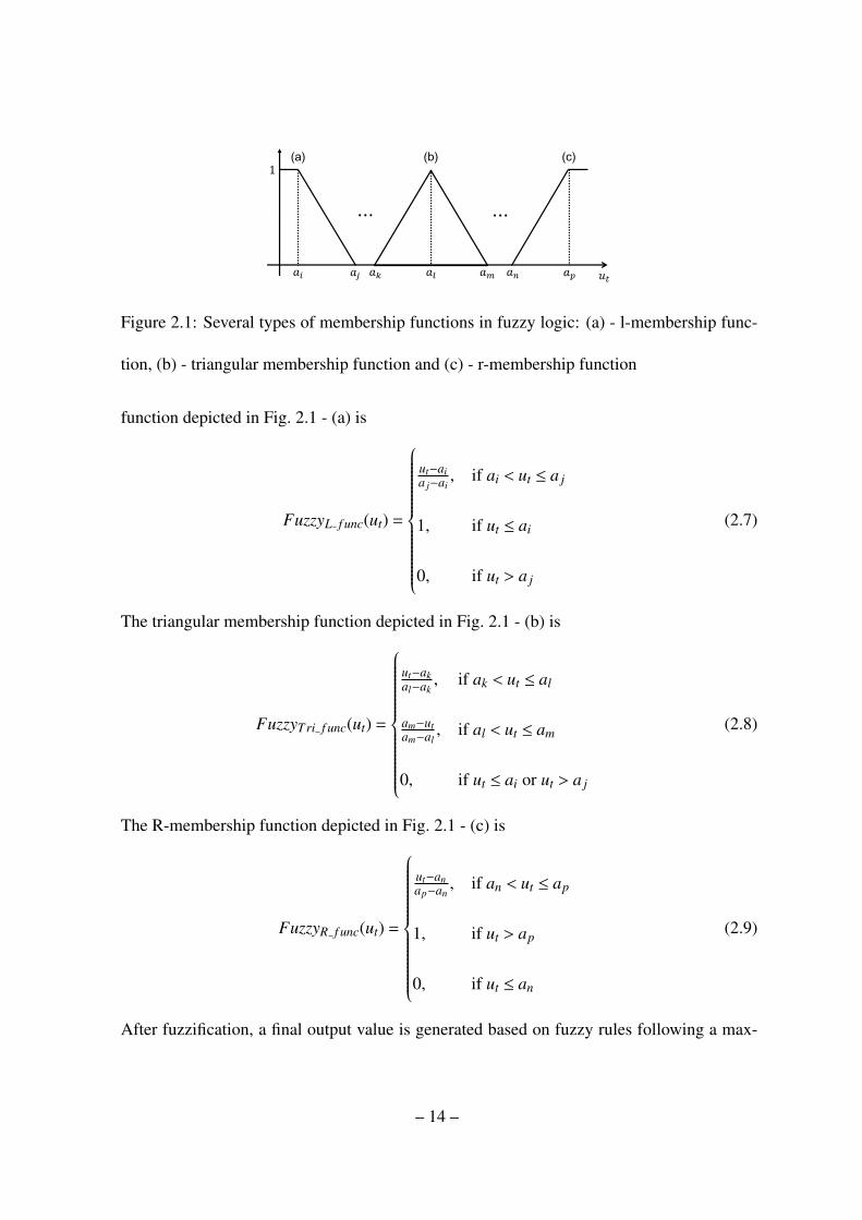
Figure 2.1: Several types of membership functions in fuzzy logic: (a) - l-membership func-
tion, (b) - triangular membership function and (c) - r-membership function
function depicted in Fig. 2.1 - (a) is
FuzzyL f unc(ut) =
ut−aia j−ai
, if ai < ut ≤ a j
1, if ut ≤ ai
0, if ut > a j
(2.7)
The triangular membership function depicted in Fig. 2.1 - (b) is
FuzzyTri f unc(ut) =
ut−akal−ak
, if ak < ut ≤ al
am−utam−al
, if al < ut ≤ am
0, if ut ≤ ai or ut > a j
(2.8)
The R-membership function depicted in Fig. 2.1 - (c) is
FuzzyR f unc(ut) =
ut−anap−an
, if an < ut ≤ ap
1, if ut > ap
0, if ut ≤ an
(2.9)
After fuzzification, a final output value is generated based on fuzzy rules following a max-
– 14 –

min composition process.
µko′ = min[ min[µk
1,µk2, · · · ,µ
kj], µ
koutput] (2.10)
µo =⋃m
k=1µko′ (2.11)
where k is the fuzzy rule number and m is the number of fuzzy rules.
The final output value, as an immediate reward for reinforcement learning, is calculated
by the center-of-mass method according to (2.12).
τt+1 =
∫uµo(u)du∫µo(u)du
(2.12)
– 15 –

Chapter 3
Interaction mechanism between bio-insect and ar-
tificial robot
3.1 Introduction
In this chapter, we propose interaction mechanism between bio-insect and artificial robot
and related hardware system (Son & Ahn, 2014).
3.1.1 Platform setup for verifying interaction mechanism
The model of bio-insect and experiments
The selection of a bio-insect is crucial in this experiment. First, the physical size of the bio-
insect has to be same as the artificial robot because similar size is the most important factor
in allowing interaction between each other. Also, we need to select a bio-insect that has good
physical strength, long life, and responds well to the robot’s actuation. For this reason, in
related research, cockroaches are popularly used because of their strong physical strength and
long life in extreme environments. However, cockroaches are very fast and thus not easy to
control using an artificial robot. We test various species of insects to empirically select a bio-
insect that is appropriate for our purposes. From numerous tests, Serrognathus platymelus
castanicolor Motschulsky or the stag beetle shows good movement over flat surface. Also it
– 16 –

has an average lifespan of two years and has good physical strength. The disadvantage of
using this bio-insect is that it is a nocturnal insect and not as sensitive as the cockroach. This
reduced sensitivity makes it difficult to actuate the insect using artificial robots. Fig. 3.1 - (a)
shows a photograph of the bio-insect chosen for this experiment.
To determine the interaction between the bio-insect and artificial robot, we test the move-
ment of the artificial robots in response to such variables as light, vibration, wind, and obsta-
cle. However, the bio-insect still has the problem of not being sensitive to normal actuation.
The reactions of the bio-insect are typically contrary to our expectations. For example, we
expect the insect to escape the robot when it approaches the insect. However, the insect fre-
quently approaches the robot and even tries to climb the robot. Thus, we can not drive the
insect towards a desired point. Nevertheless, after many experimental tests, we have found a
clue as to how the bio-insect reacts to specific actuation.
In a simple experiment, we attaches a small piece of paper as an obstacle in the work-
ing range of the left antenna side of the bio-insect. Thereafter, the bio-insect can sense that
an obstacle exists on its left side, so its trajectory follows a circular path. This simple ex-
perimental result enables us to determine that the bio-insect relies on information from its
antenna.
Artificial robot: an agent
To perform more advanced experiments, we redesign e-puck robots to produce the desired
actuation for artificial robot agents. In an e-puck robot, first of all, there are not enough ports
to control other actuators and voltage is not enough to make strong actuators. Therefore, we
– 17 –

Figure 3.1: (a) - The stag beetles (female(left) and male(right)) (b) - advanced experiment
using dual fan motors, (c) - different temperature of air, (d) - different odor sources
add one more micro controller composed of a 7.4V Li-ion battery, voltage regulator for the
computer chips, micro controller, and max3232 to communicate between micro controllers.
We then revise the source program of the e-puck robot to create a new program source for
the added micro controller.
After installing the artificial robot’s hardware platform, we are able to perform experi-
mental tests in a remote area to prevent interference that occurs indirect influences on the
movement of the bio-insect. In this advanced experiment, we focus on how to stimulate the
antenna of the bio-insect effectively. Therefore, we use dual fan motors that forced air blow
toward the bio-insect at different times and different directions, respectively, and air-pump
motors to spread hot, cold, or specific odor sources. In some cases, we use a vibration motor
– 18 –
to obtain a stronger response when the above mentioned actuators are executed.
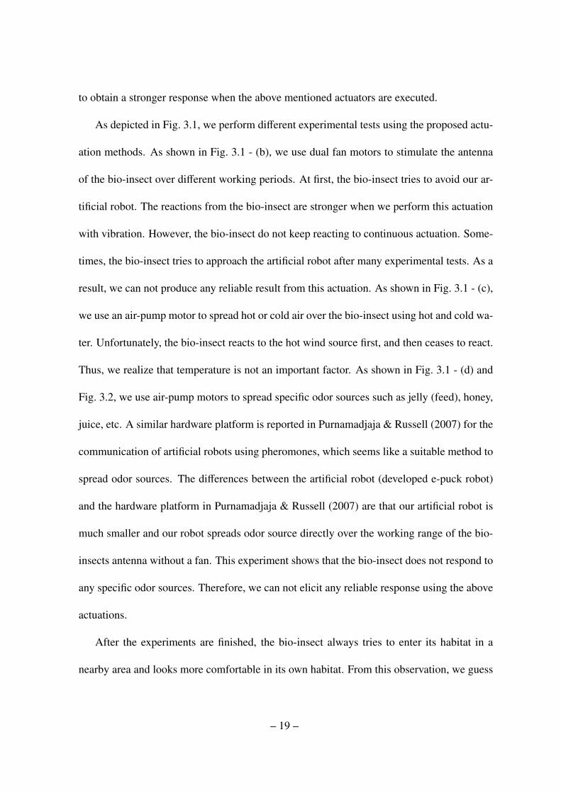
As depicted in Fig. 3.1, we perform different experimental tests using the proposed actu-
ation methods. As shown in Fig. 3.1 - (b), we use dual fan motors to stimulate the antenna
of the bio-insect over different working periods. At first, the bio-insect tries to avoid our ar-
tificial robot. The reactions from the bio-insect are stronger when we perform this actuation
with vibration. However, the bio-insect do not keep reacting to continuous actuation. Some-
times, the bio-insect tries to approach the artificial robot after many experimental tests. As a
result, we can not produce any reliable result from this actuation. As shown in Fig. 3.1 - (c),
we use an air-pump motor to spread hot or cold air over the bio-insect using hot and cold wa-
ter. Unfortunately, the bio-insect reacts to the hot wind source first, and then ceases to react.
Thus, we realize that temperature is not an important factor. As shown in Fig. 3.1 - (d) and
Fig. 3.2, we use air-pump motors to spread specific odor sources such as jelly (feed), honey,
juice, etc. A similar hardware platform is reported in Purnamadjaja & Russell (2007) for the
communication of artificial robots using pheromones, which seems like a suitable method to
spread odor sources. The differences between the artificial robot (developed e-puck robot)
and the hardware platform in Purnamadjaja & Russell (2007) are that our artificial robot is
much smaller and our robot spreads odor source directly over the working range of the bio-
insects antenna without a fan. This experiment shows that the bio-insect does not respond to
any specific odor sources. Therefore, we can not elicit any reliable response using the above
actuations.
After the experiments are finished, the bio-insect always tries to enter its habitat in a
nearby area and looks more comfortable in its own habitat. From this observation, we guess
– 19 –

Figure 3.2: (a) - The proposed structure of spreading an odor source with a robot using
two air-pump motors to produce airflow and one plastic bottle containing an odor source
composed of sawdust taken from the habitat of the bio-insect. (b) - robot agent
that the bio-insect knows its own habitat odor. To confirm this notion, we conduct experi-
mental test for case of Fig. 3.1 - (d) using sawdust from its habitat. Ultimately, we are able
to obtain good results. When the artificial robot spreads an odor source that consists of water
and sawdust from its habitat, the bio-insect follows the odor source to find the location of its
habitat. As a result, we are able to entice the bio-insect continuously using this specific odor
source. Based on this result, we are able to determine an interaction method to achieve our
goal.
3.1.2 Experimental setup for verifying interaction mechanism
To evaluate our designed actuation method, we use the experiment platform as illustrated
in Fig. 3.3. The figure indicates the initial position of the agent, bio-insect, and goal area.
– 20 –
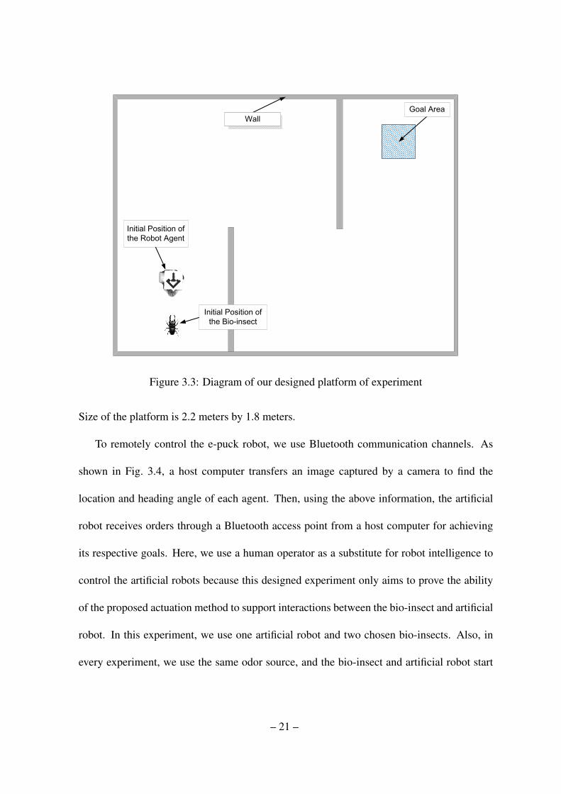
Figure 3.3: Diagram of our designed platform of experiment
Size of the platform is 2.2 meters by 1.8 meters.
To remotely control the e-puck robot, we use Bluetooth communication channels. As
shown in Fig. 3.4, a host computer transfers an image captured by a camera to find the
location and heading angle of each agent. Then, using the above information, the artificial
robot receives orders through a Bluetooth access point from a host computer for achieving
its respective goals. Here, we use a human operator as a substitute for robot intelligence to
control the artificial robots because this designed experiment only aims to prove the ability
of the proposed actuation method to support interactions between the bio-insect and artificial
robot. In this experiment, we use one artificial robot and two chosen bio-insects. Also, in
every experiment, we use the same odor source, and the bio-insect and artificial robot start
– 21 –

Robots
Figure 3.4: Hardware platform
at the initial position as depicted in Fig. 3.3.
Every beginning of the experiment, we need to check reactivity of the chosen bio-insect.
If the reactivity of the bio-insect is sufficient to conduct the experiment, then we conduct the
experiment using the bio-insect. We conduct the experiment for two days and do not exceed
the predefined maximum number of repetitions for a bio-insect and maximum durations
per episode during the experiment. Here, the maximum number of repetitions is 3 and the
maximum duration per episode is 25 minutes.
– 22 –
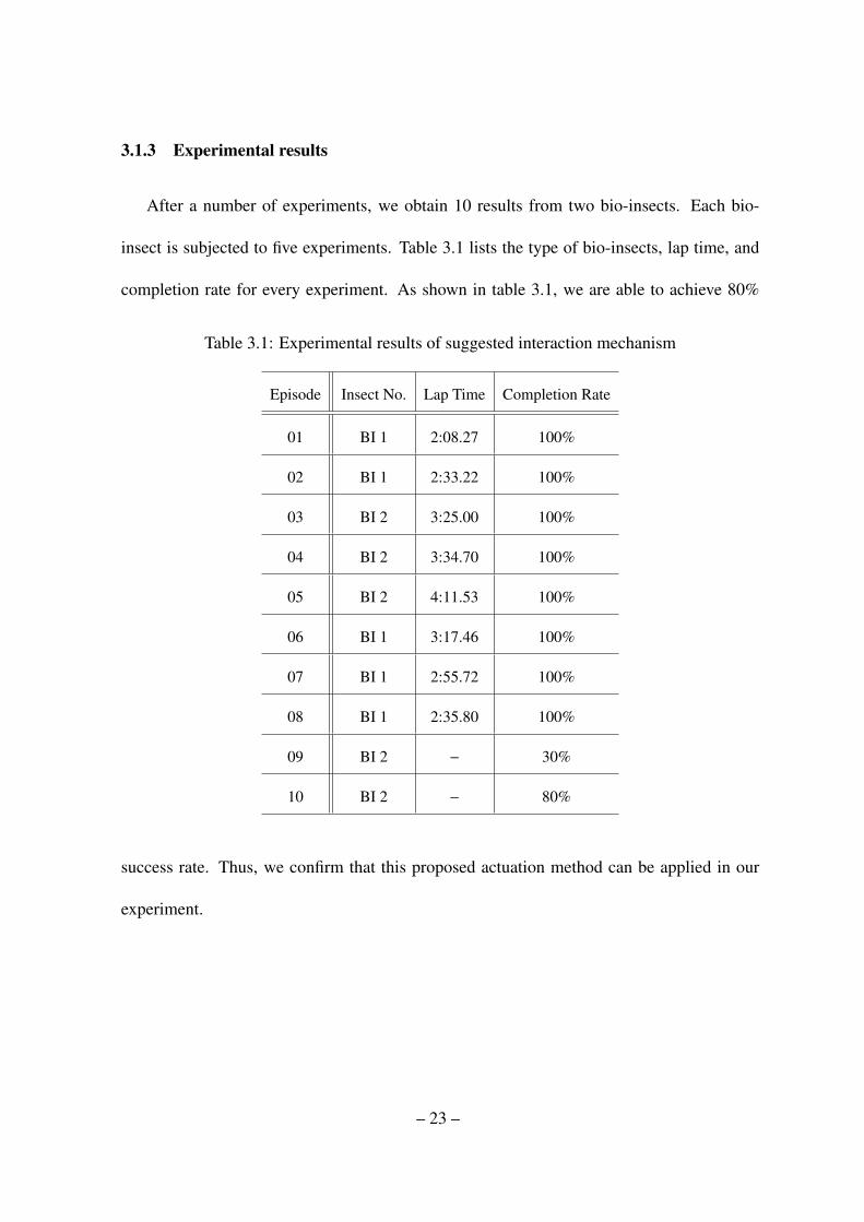
3.1.3 Experimental results
After a number of experiments, we obtain 10 results from two bio-insects. Each bio-
insect is subjected to five experiments. Table 3.1 lists the type of bio-insects, lap time, and
completion rate for every experiment. As shown in table 3.1, we are able to achieve 80%
Table 3.1: Experimental results of suggested interaction mechanism
Episode Insect No. Lap Time Completion Rate
01 BI 1 2:08.27 100%
02 BI 1 2:33.22 100%
03 BI 2 3:25.00 100%
04 BI 2 3:34.70 100%
05 BI 2 4:11.53 100%
06 BI 1 3:17.46 100%
07 BI 1 2:55.72 100%
08 BI 1 2:35.80 100%
09 BI 2 − 30%
10 BI 2 − 80%
success rate. Thus, we confirm that this proposed actuation method can be applied in our
experiment.
– 23 –

3.2 Conclusion
We have presented an enticing method for an interaction between stag beetle and mo-
bile robots. From our designed experimental results, we have shown that the interaction
mechanism can entice the bio-insect from initial point to goal point with 80 percentage of
success rate. As mentioned in previous section, we have used a human operator to entice the
bio-insect, and the human operator can be considered as a fully learned robot to entice the
bio-insect towards desired goal. However, the experiment can not perfectly achieve the task
due to complex and unpredictable behaviors of the bio-insect. For example, reactions of a
bio-insect from generated action of robots are always not equal to what we expected and the
amount of reaction is different in every trial. In those conditions, the robot needs to learn
precise knowledge to entice the bio-insect towards desired goal area. To deal with the prop-
erties of the bio-insect, in next chapter, we will introduce fuzzy-logic-based reinforcement
learning.
– 24 –

Chapter 4
Fuzzy-logic-based reinforcement learning
4.1 Introduction
In this chapter, we propose fuzzy-logic-based reinforcement learning for interaction be-
tween bio-insect and artificial robot (Son & Ahn, 2014). The ultimate goal of this chapter
is to entice bio-insects towards desired goal areas using artificial robots without any human
aid. As a second step, the main objective of this chapter is to entice a bio-insect towards the
desired goal area using an artificial robot with the fuzzy-logic-based reinforcement learn-
ing. In this chapter, reinforcement learning and fuzzy logic play key roles in operating the
architecture.
This chapter consists of the following sections. In section 4.2, we present the fuzzy-
logic-based reinforcement learning architecture with respect to real experiments. In section
4.3, we introduce the experimental results. Section 4.4 concludes this chapter.
4.2 Fuzzy logic-based reinforcement learning
4.2.1 Design of fuzzy logic-based reinforcement learning
Defining states
We apply the interaction mechanism introduced in previous chapter to a fuzzy-logic-based
reinforcement learning architecture to entice the bio-insect towards desired point. For the
– 25 –

experiment, we formulate the experimental platform as depicted in Fig. 4.1. To assess the
current location, we define S tate loc(x,y), which consists of 24 S tate loc(x) states and 16
S tate loc(y) states to recognize the current location, as illustrated in Fig. 4.1-(a). These
S tate loc(x) and S tate loc(y) do not affect the robot’s learning mechanism. The states oper-
ate to maintain the experiment from the beginning.
Fig. 4.1 - (a) shows the start point and goal area of the bio-insect, guiding points and
the walls of a simple maze. Compared with the platform illustrated in Fig. 3.3 in previous
chapter, the platform shown in Fig. 4.1 is composed of a simple maze structure because the
real experiment considering an optimal path requires a long computation time. Also, we
focus on verifying that the artificial robot can entice the bio-insect based on the architecture
without any human aid. Thus, we do not consider how the robot could learn the optimal
trajectory. Instead, we use three guiding points as lighthouses to reach the desired goal
point. Following algorithm 1 helps determine the selection of a guiding point based on the
current location of the bio-insect.
When we execute the experiment for the interaction mechanism, we find that when the
bio-insect reaches a wall, then it only tries following the wall without any reactions from the
specific odor source we found in previous chapter. Therefore, we impose the restricted states
shaded red near the wall as depicted in Fig. 4.1. In this scheme, if the bio-insect reaches the
restricted states during an experiment, the experiment will be stopped automatically by the
host computer. Upon the first interaction of every episode, an artificial robot starts to move
towards the bio-insect. As described in Algorithm 1, when the bio-insect is located in Area
# 1, its guiding point is S ub− goal # 1. Likewise, when the bio-insect is located in Area #
– 26 –

(a)
(b)
Figure 4.1: (a) - Designed state for recognizing current state of location and (b)- photograph
of experimental platform
2 or Area # 3, then its sub-goal points will be S ub−goal # 2 or S ub−goal # 3 (goal point),
respectively.
To recognize the current status between the bio-insect and the artificial robot agent and
to select a desired action at at iteration t, we define states that consist of a heading angle
– 27 –

Algorithm 1 Recognizing the current area and selecting a sub-goal for a bio-insectInput: Current area (Area) and current location (S tate loc(x,y))
Output: Newly recognized area (Area) for selecting a S ub−goal
if Area = #1 then
if S tate loc(x) < 8 then
Area← #2
else
Area← #1
end if
else if Area = #2 then
if S tate loc(x) > 15 then
Area← #3
else if S tate loc(y) > 9 then
Area← #1
else
Area← #2
end if
else if Area = #3 then
if S tate loc(x) < 14 then
Area← #2
else
Area← #3
end if
end if
component and a goal direction component for the bio-insect as illustrated in Fig. 4.3. The
heading angle and the goal direction are divided into eight parts, each separated by 45◦
degrees, and all of the centers of the divided parts, which are shaded green, are action points
used to spread the odor source towards the bio-insect. To avoid collision, the artificial robot
moves around the bio-insect at a restricted distance range between them. The eight current
states are as follows, each of which features a heading angle and a goal angle : (1) 337.5◦
< θHeading, θGoal or θHeading, θGoal ≤ 22.5◦, (2) 22.5◦ < θHeading, θGoal ≤ 67.5◦, (3) 67.5◦ <
θHeading, θGoal ≤ 112.5◦, (4) 112.5◦ < θHeading, θGoal ≤ 157.5◦, (5) 157.5◦ < θHeading, θGoal ≤
– 28 –

202.5◦, (6) 202.5◦ < θHeading, θGoal ≤ 247.5◦, (7) 247.5◦ < θHeading, θGoal ≤ 292.5◦, and (8)
292.5◦ < θHeading, θGoal ≤ 337.5◦.
As illustrated in Fig. 4.1, the current state is recognized based on the heading angle of
the bio-insect and angle of the guiding point at the current point. If the current states are
recognized, then the agent can choose one of eight places as an actuating point to entice the
bio-insect. Our experimental platform adopts a simple maze structure to avoid any accidental
success of the experiment. Thus, to make the bio-insect reach the desired destination area,
the artificial robot should take the wall into account and entice the bio-insect around the wall.
Thus, we use three guiding points including two sub-goal points as mediators located along
the recommended trajectory for the bio-insect and another one located at the center of the
goal area.
Framework of fuzzy logic-based reinforcement learning
The main fuzzy-logic-based reinforcement learning architecture is depicted in Fig. 4.4. Based
on the reinforcement learning architecture, fuzzy logic generates a reward signal τ from the
collected reaction of the bio-insect.
When the artificial robot recognizes a current state at iteration t, then over a possible set
of actions A it tries to choose an action a in the current state s. After an action a is executed,
reaction information including the variation in distance ∆dt between the sub-goal point and
the bio-insect and the variation in distance ∆et between the artificial robot and the bio-insect
– 29 –

are collected. Here, ∆dt and ∆et are calculated as
∆dt = ‖pbt s− pGoal
t s ‖− ‖pbt e− pGoal
t e ‖ (4.1)
∆et = ‖pkt s− pb
t s‖− ‖pkt s− pb
t e‖ (4.2)
where pbt , pk
t , and pGoalt indicate the position of the bio-insect, the artificial robot, and the
goal, respectively, pt ∈ R2, {t s, t e} ∈ t (t s and t e indicate the start time and end time of the
selected action a at iteration step t, respectively) and ‖ · ‖ is the Euclidean norm.
Based on the fuzzy rules described in Table 4.1, the input variables ∆dt and ∆et are
calculated by following input membership functions (4.3) and (4.4) and output membership
functions (4.5) as depicted in Fig. 4.5 - (a), (b), and (c).
µ∆dt = {VGd,GDd,NMd,PRd,VPd} (4.3)
µ∆et = {VGe,GDe,NMe,PRe,VPe} (4.4)
µo = {VGo,GDo,NMo,PRo,VPo} (4.5)
where VG, GD, NM, PR, and VP indicate very good, good, normal, poor, and very poor,
respectively.
The fuzzy rules have the following structure.
µi = If (∆dt is µi∆dt
) and (∆et is µi∆et
), then output is µio
Then, the calculated values ∆dt and ∆et are converted by a fuzzification process using the
defined fuzzy sets depicted in Fig. 4.5 - (a) and (b).
After the fuzzification process, the converted values are calculated by (4.6) and (4.7)
through a max-min composition process. Then, using the fuzzy rules shown in Table 4.1, all
– 30 –

Table 4.1: 25 Fuzzy rules
F01: IF ∆dt is VGd and ∆et is VGe, THEN Output is VGo
F02: IF ∆dt is VGd and ∆et is GDe, THEN Output is GDo
F03: IF ∆dt is VGd and ∆et is NMe, THEN Output is NMo
F04: IF ∆dt is VGd and ∆et is BDe, THEN Output is BDo
F05: IF ∆dt is VGd and ∆et is VBe, THEN Output is VBo
F06: IF ∆dt is GDd and ∆et is VGe, THEN Output is GDo
F07: IF ∆dt is GDd and ∆et is GDe, THEN Output is NMo
F08: IF ∆dt is GDd and ∆et is NMe, THEN Output is NMo
F09: IF ∆dt is GDd and ∆et is BDe, THEN Output is BDo
F10: IF ∆dt is GDd and ∆et is VBe, THEN Output is VBo
F11: IF ∆dt is NMd and ∆et is VGe, THEN Output is VBo
F12: IF ∆dt is NMd and ∆et is GDe, THEN Output is BDo
F13: IF ∆dt is NMd and ∆et is NMe, THEN Output is NMo
F14: IF ∆dt is NMd and ∆et is BDe, THEN Output is NMo
F15: IF ∆dt is NMd and ∆et is VBe, THEN Output is NMo
F16: IF ∆dt is BDd and ∆et is VGe, THEN Output is BDo
F17: IF ∆dt is BDd and ∆et is GDe, THEN Output is BDo
F18: IF ∆dt is BDd and ∆et is NMe, THEN Output is NMo
F19: IF ∆dt is BDd and ∆et is BDe, THEN Output is NMo
F20: IF ∆dt is BDd and ∆et is VBe, THEN Output is NMo
F21: IF ∆dt is VBd and ∆et is VGe, THEN Output is VBo
F22: IF ∆dt is VBd and ∆et is GDe, THEN Output is BDo
F23: IF ∆dt is VBd and ∆et is NMe, THEN Output is NMo
F24: IF ∆dt is VBd and ∆et is BDe, THEN Output is NMo
F25: IF ∆dt is VBd and ∆et is VBe, THEN Output is NMo
values are expressed into output fuzzy sets depicted in Fig.4.5 - (c) by (4.7). All outputs are
– 31 –

combined into the aggregation of output fuzzy sets.
µio′ = min[ min[µi
d(∆dt),µie(∆et)], µi
o] (4.6)
µo(u) = max25i=1µ
io′ (4.7)
The final output as an immediate reward can be calculated by the center of mass method
(4.8).
τt+1 =
∫uµo(u)du∫µo(u)du
(4.8)
All procedures of fuzzy-logic-based reinforcement learning are illustrated in Fig. 4.6 as a
flow chart and described in Algorithm 2 as an algorithm structure.
4.3 Experimental results
We conduct two types of experiments as follows. First type of experiments use fuzzy-
logic based reinforcement learning as Exp. 1 and another type of experiments use generating
a reward by simple algorithms as described in Algorithm 3 for Exp. 2. The algorithm 3
for Exp. 2 only generates both constant rewards as 1 or −1 when the bio-insect follows the
artificial robot (∆et > 25). In that case, if variation in distance ∆dt between the sub-goal
point and the bio-insect is reduced, then the robot will receive a reward as 1. Reversely, if
variation in distance ∆dt is increased, then the robot will receive a reward as −1. Commonly,
both two types of experiments use same inputs ∆dt and ∆et calculated by Eq. 4.1 and 4.2. In
contrast, fuzzy-logic-based reinforcement learning generates a precise reward signal based
on the inputs ∆dt and ∆et as introduced in previous section.
For the experiments, we use the following parameters: learning rate α = 0.95, discount
factor Γ = 0.95, and ε = 0.25. Also, for every episode the parameter values are decreased
– 32 –

Algorithm 2 Fuzzy-logic-based reinforcement learningif Current episode == 1 then
Initialize all states and all values
elseLoad previous states and values
end ifCurrent number of iterations t← 0
Current number of episodes ep← ep + 1
while (The bio-insect does not approach goal state or illegal state) or (Number of current iterations
≤ defined maximum number of iterations) doRecognize current states S tate loc(x,y) and state(θHeading, θGoal)
if Randomly chosen value ε ≥ εt thenSelect the best action on a possible set of actions at current state
elseRandomly choose an action on a possible set of actions at current state
end ifDo an action and calculate changes of movement of the bio-insect (∆dt and ∆et)
µio′ = min[ min[µi
d(∆dt),µie(∆et)], µi
o]
µo(u) = max25i=1µ
io′
Calculate a reward value τt+1 =
∫uµo(u)du∫µo(u)du
Qt+1(s,a)← (1−αep)Qt(s,a) +αep(τt+1 +Γmaxa Qt(s, a))
t← t + 1
end whileif αep > αe thenαep+1← αep−∆α
elseαep+1← αc
end ifif εep > εe thenεep+1← εep−∆ε
elseεep+1← εc
end if
– 33 –
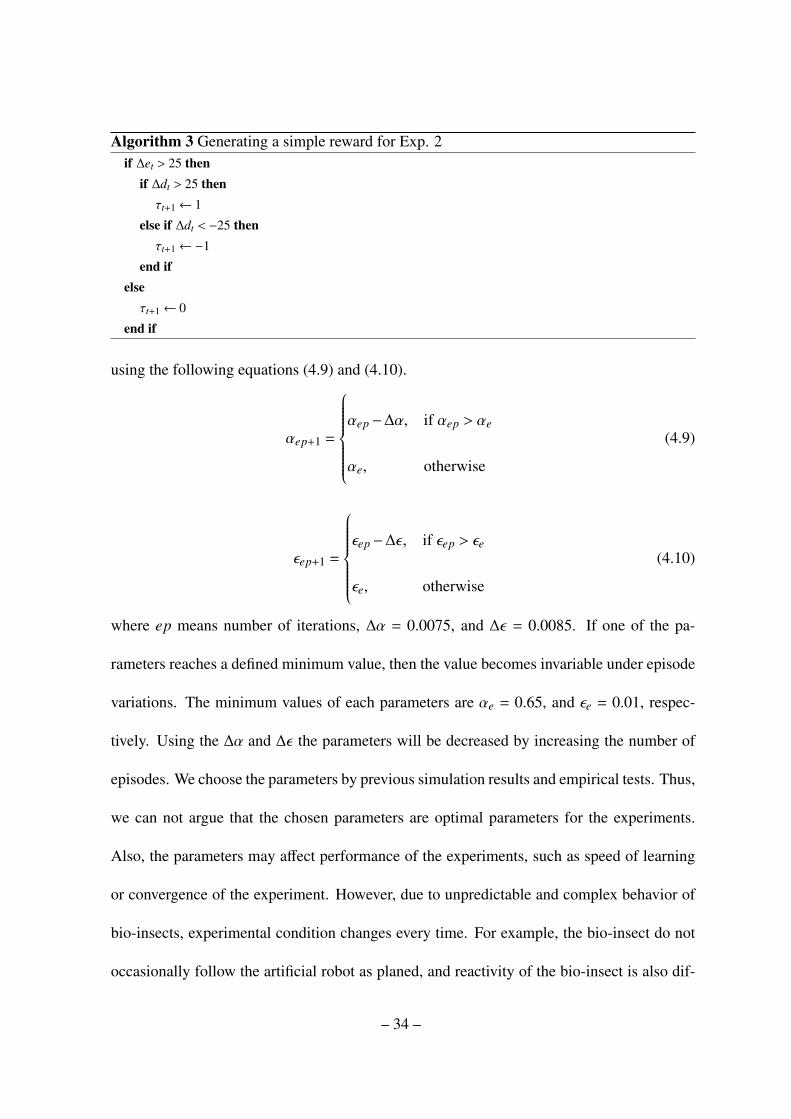
Algorithm 3 Generating a simple reward for Exp. 2if ∆et > 25 then
if ∆dt > 25 thenτt+1← 1
else if ∆dt < −25 thenτt+1←−1
end ifelseτt+1← 0
end if
using the following equations (4.9) and (4.10).
αep+1 =
αep−∆α, if αep > αe
αe, otherwise
(4.9)
εep+1 =
εep−∆ε, if εep > εe
εe, otherwise
(4.10)
where ep means number of iterations, ∆α = 0.0075, and ∆ε = 0.0085. If one of the pa-
rameters reaches a defined minimum value, then the value becomes invariable under episode
variations. The minimum values of each parameters are αe = 0.65, and εe = 0.01, respec-
tively. Using the ∆α and ∆ε the parameters will be decreased by increasing the number of
episodes. We choose the parameters by previous simulation results and empirical tests. Thus,
we can not argue that the chosen parameters are optimal parameters for the experiments.
Also, the parameters may affect performance of the experiments, such as speed of learning
or convergence of the experiment. However, due to unpredictable and complex behavior of
bio-insects, experimental condition changes every time. For example, the bio-insect do not
occasionally follow the artificial robot as planed, and reactivity of the bio-insect is also dif-
– 34 –
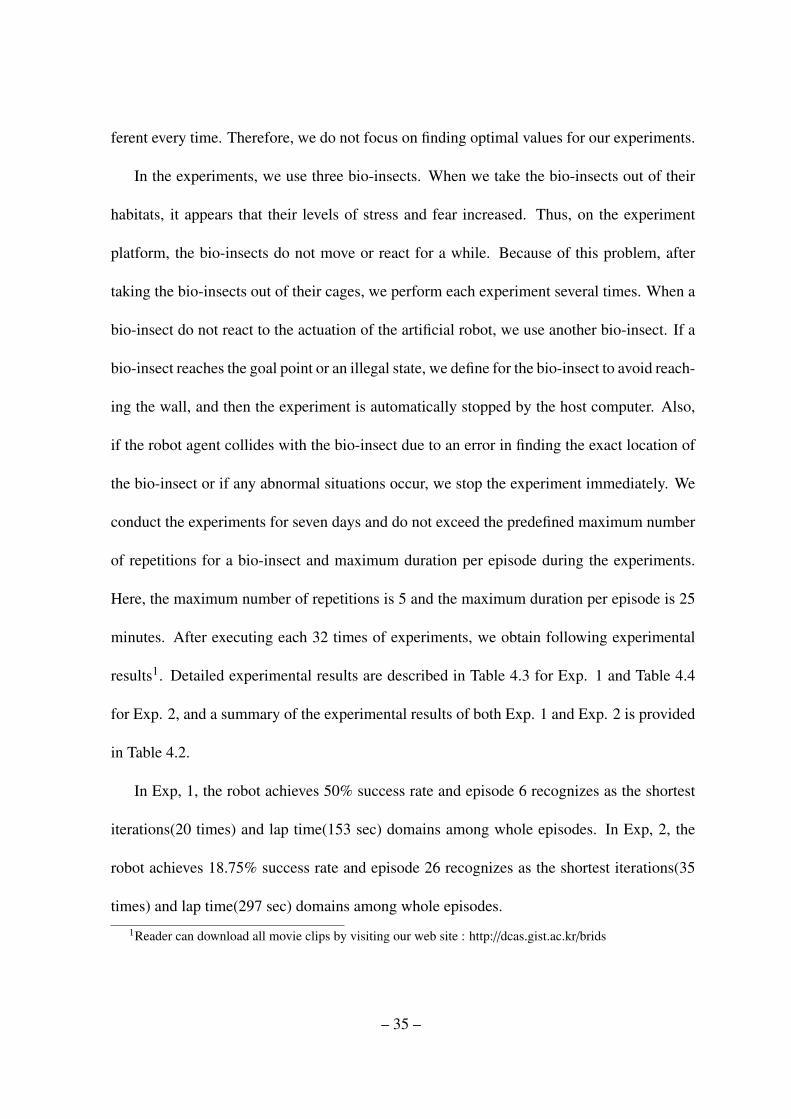
ferent every time. Therefore, we do not focus on finding optimal values for our experiments.
In the experiments, we use three bio-insects. When we take the bio-insects out of their
habitats, it appears that their levels of stress and fear increased. Thus, on the experiment
platform, the bio-insects do not move or react for a while. Because of this problem, after
taking the bio-insects out of their cages, we perform each experiment several times. When a
bio-insect do not react to the actuation of the artificial robot, we use another bio-insect. If a
bio-insect reaches the goal point or an illegal state, we define for the bio-insect to avoid reach-
ing the wall, and then the experiment is automatically stopped by the host computer. Also,
if the robot agent collides with the bio-insect due to an error in finding the exact location of
the bio-insect or if any abnormal situations occur, we stop the experiment immediately. We
conduct the experiments for seven days and do not exceed the predefined maximum number
of repetitions for a bio-insect and maximum duration per episode during the experiments.
Here, the maximum number of repetitions is 5 and the maximum duration per episode is 25
minutes. After executing each 32 times of experiments, we obtain following experimental
results1. Detailed experimental results are described in Table 4.3 for Exp. 1 and Table 4.4
for Exp. 2, and a summary of the experimental results of both Exp. 1 and Exp. 2 is provided
in Table 4.2.
In Exp, 1, the robot achieves 50% success rate and episode 6 recognizes as the shortest
iterations(20 times) and lap time(153 sec) domains among whole episodes. In Exp, 2, the
robot achieves 18.75% success rate and episode 26 recognizes as the shortest iterations(35
times) and lap time(297 sec) domains among whole episodes.
1Reader can download all movie clips by visiting our web site : http://dcas.gist.ac.kr/brids
– 35 –
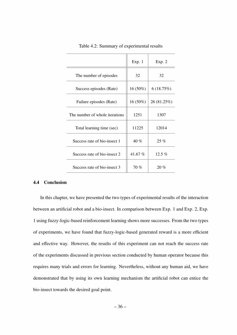
Table 4.2: Summary of experimental results
Exp. 1 Exp. 2
The number of episodes 32 32
Success episodes (Rate) 16 (50%) 6 (18.75%)
Failure episodes (Rate) 16 (50%) 26 (81.25%)
The number of whole iterations 1251 1307
Total learning time (sec) 11225 12014
Success rate of bio-insect 1 40 % 25 %
Success rate of bio-insect 2 41.67 % 12.5 %
Success rate of bio-insect 3 70 % 20 %
4.4 Conclusion
In this chapter, we have presented the two types of experimental results of the interaction
between an artificial robot and a bio-insect. In comparison between Exp. 1 and Exp. 2, Exp.
1 using fuzzy-logic-based reinforcement learning shows more successes. From the two types
of experiments, we have found that fuzzy-logic-based generated reward is a more efficient
and effective way. However, the results of this experiment can not reach the success rate
of the experiments discussed in previous section conducted by human operator because this
requires many trials and errors for learning. Nevertheless, without any human aid, we have
demonstrated that by using its own learning mechanism the artificial robot can entice the
bio-insect towards the desired goal point.
– 36 –
Commonly, due to lack of knowledge, the robot has failed to entice the bio-insect at the
first and second episodes. From the episode 3 in Exp. 1, the number of success cases has
gradually increased with increasing number of episodes. However, the number of iterations
and lap time (drawn with lines) for successful cases fluctuate with increasing number of
episode. These experimental results are caused by the complex and uncertain behavior of
the bio-insect. Normally, the bio-insect follows the artificial well. However, reactivity of the
bio-insect is different in every time. Occasionally, the bio-insect do not follow the artificial
robot and the bio-insect acts as if it trying to escape its current place or to find its real habitat.
To deal with the behavior, the artificial robot needs to learn how to entice the bio-insect at
every recognized state. Therefore, we can not obtain converged results in the number of
iteration and lap time domains. This phenomenon also can be found in Exp. 2. At least, in
Exp. 1, success rate of the episodes has increased with increasing number of episodes. From
the point of view, we can make sure that learning has happened all episodes.
When we tries to find available interaction mechanisms and to entice a bio-insect towards
a specific goal area using a robot by human operator as described in Section 3, a bio-insect
that we have chosen shows uncertain and complex behavior. For example, the bio-insect do
not occasionally follow the artificial robot as planed and reactivity of the bio-insect is also
different every time. These behaviors may be caused by its own intelligence to survive in na-
ture. Therefore the behaviors make an artificial robot difficult to apply artificial intelligence
to entice the bio-insect to control movement of the bio-insect. In these conditions, the robot
needs to learn specific knowledge to entice the bio-insect. As one of the proper solutions,
we use reinforcement learning and fuzzy logic as an intelligence structure. It is well known
– 37 –
that the reinforcement learning is similar to learning mechanism of animal using positive and
negative rewards through trial-and-error process. To apply the reinforcement learning struc-
ture into an artificial robot, it is crucial to generate suitable reward for precise learning. To
generate a reward from unpredictable and complex behavior of a bio-insect, we apply fuzzy
logic to generate a reward.
The main mechanism of the learning architecture is the fuzzy-logic-based reinforcement
learning. When the artificial robot actuates to interact with the bio-insect, the reaction of
the bio-insect features complex and uncertain behavior. The behavior prevents the artificial
robot from obtaining the optimal policy under the actuation in a specific state. To handle
the behavior, we adopt fuzzy logic to express imprecise behavior. Under the defined rules of
fuzzy logic, a robot can receive appropriate reward signal based on its past actions and the
reactions of the bio-insect in a specific state. Then, after many iterations, the robot learns
where the artificial robot should perform the actuation towards the bio-insect to entice it
towards the desired point using reinforcement learning. Then, the experimental results have
showed that the artificial robot can entice the bio-insect towards the desired goal area without
any human aid.
– 38 –
(c)
(a)
(b)
Figure 4.2: Recognizing current area to select sub-goal point. According to algorithm 1,
sub-goal points to entice the bio-insect are illustrated based on current location of the bio-
insect. (a) - Area #1 and S ub−goal #1, (b) - Area #2 and S ub−goal #2, and (c) - Area #3
and S ub−goal #3
– 39 –

Actuation Point
Figure 4.3: Designed state for recognizing current state - in this case, the state of the heading
angle of the bio-insect is (2), and the state of the goal direction for the bio-insect is (4).
– 40 –
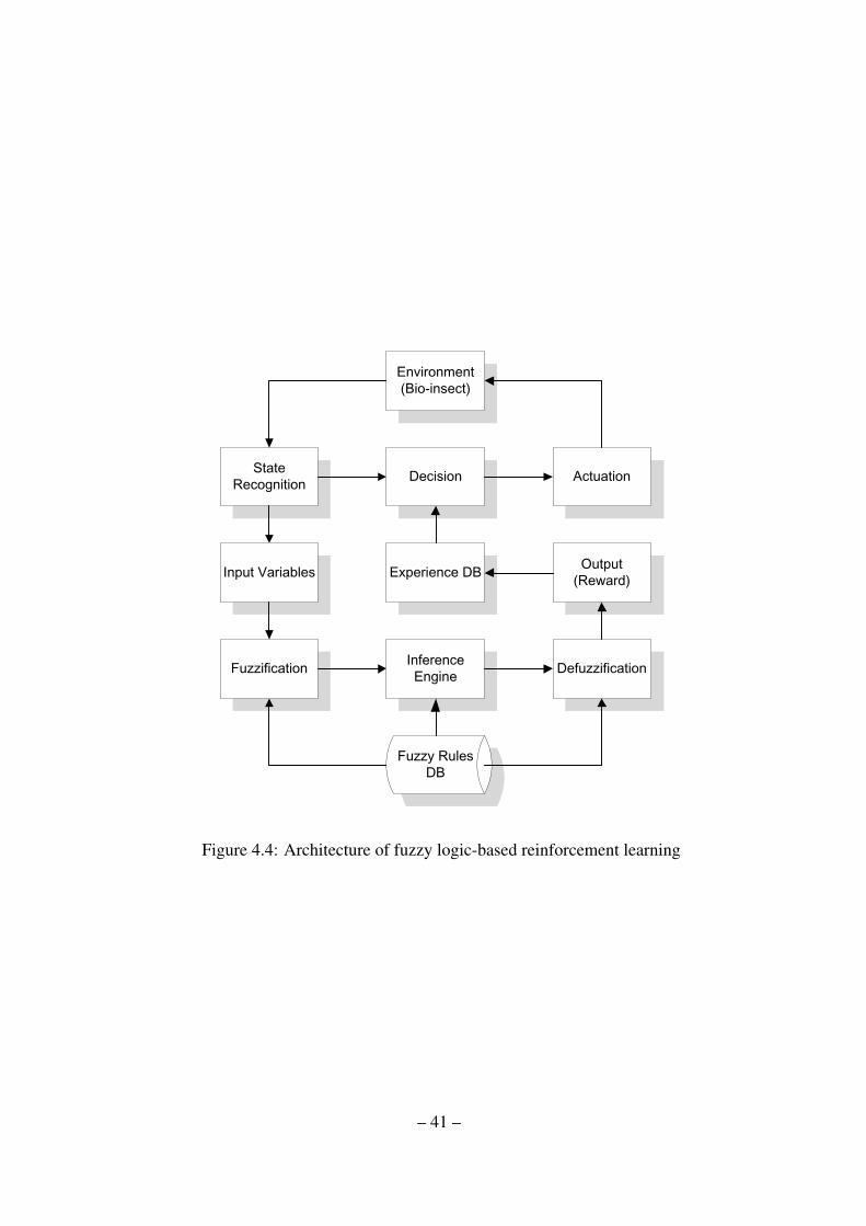
Figure 4.4: Architecture of fuzzy logic-based reinforcement learning
– 41 –
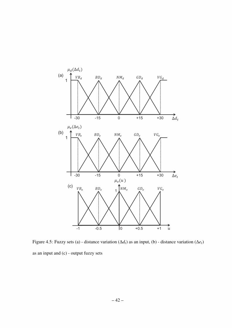
Figure 4.5: Fuzzy sets (a) - distance variation (∆dt) as an input, (b) - distance variation (∆et)
as an input and (c) - output fuzzy sets
– 42 –

Figure 4.6: Flow chart of learning mechanism of fuzzy-logic-based reinforcement learning
– 43 –

Table 4.3: Detailed experimental results for Exp. 1
Episode Iterations Lap Time(sec) Insect Result
1 57 574 BI 1 Failure2 18 153 BI 1 Failure3 37 315 BI 1 Success4 31 280 BI 1 Failure
5 31 277 BI 2 Failure6 20 153 BI 2 Success7 13 107 BI 2 Failure8 11 111 BI 2 Failure
9 43 407 BI 3 Failure10 35 304 BI 3 Success11 22 165 BI 3 Failure12 25 216 BI 3 Failure
13 30 299 BI 2 Success14 24 183 BI 2 Success15 39 407 BI 2 Failure16 34 331 BI 2 Failure
17 59 722 BI 3 Success18 48 497 BI 3 Success19 34 311 BI 3 Failure20 39 360 BI 3 Success
21 30 374 BI 3 Success22 78 744 BI 1 Failure23 36 327 BI 1 Success24 73 518 BI 1 Failure
25 38 266 BI 3 Success26 43 328 BI 3 Success27 94 732 BI 3 Failure28 35 227 BI 3 Failure
29 46 382 BI 1 Success30 37 257 BI 1 Success31 54 596 BI 2 Success32 37 302 BI 2 Success
– 44 –
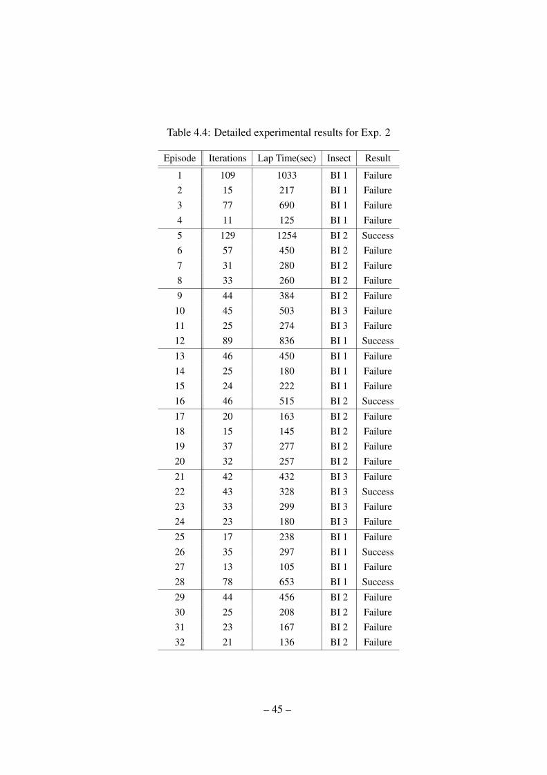
Table 4.4: Detailed experimental results for Exp. 2
Episode Iterations Lap Time(sec) Insect Result
1 109 1033 BI 1 Failure2 15 217 BI 1 Failure3 77 690 BI 1 Failure4 11 125 BI 1 Failure
5 129 1254 BI 2 Success6 57 450 BI 2 Failure7 31 280 BI 2 Failure8 33 260 BI 2 Failure
9 44 384 BI 2 Failure10 45 503 BI 3 Failure11 25 274 BI 3 Failure12 89 836 BI 1 Success
13 46 450 BI 1 Failure14 25 180 BI 1 Failure15 24 222 BI 1 Failure16 46 515 BI 2 Success
17 20 163 BI 2 Failure18 15 145 BI 2 Failure19 37 277 BI 2 Failure20 32 257 BI 2 Failure
21 42 432 BI 3 Failure22 43 328 BI 3 Success23 33 299 BI 3 Failure24 23 180 BI 3 Failure
25 17 238 BI 1 Failure26 35 297 BI 1 Success27 13 105 BI 1 Failure28 78 653 BI 1 Success
29 44 456 BI 2 Failure30 25 208 BI 2 Failure31 23 167 BI 2 Failure32 21 136 BI 2 Failure
– 45 –
10
20
30
40
50
60
70
80
90
100
0 5 10 15 20 25 30
100
200
300
400
500
600
700
800
Nu
mb
er
of
Ite
rati
on
s
La
p T
ime
(se
c)Number of Episodes
Experimental Results
Iteration of Success CaseLab Time of Success Case
Iteration of Failure CaseLab Time of Failure Case
Figure 4.7: Results of the Exp. 1 - In this figure, four types of results are indicated: success
case of iterations and lap time (drawn with lines) and failure case of iterations and lap time,
respectively
– 46 –

0
20
40
60
80
100
120
140
0 5 10 15 20 25 30
0
200
400
600
800
1000
1200
1400
Nu
mb
er
of
Ite
rati
on
s
La
p T
ime
(se
c)Number of Episodes
Experimental Results
Iteration of Success CaseLab Time of Success Case
Iteration of Failure CaseLab Time of Failure Case
Figure 4.8: Results of the Exp. 2 - In this figure, four types of results are indicated: success
case of iterations and lap time (drawn with lines) and failure case of iterations and lap time,
respectively
– 47 –
01 02
03 04
05 06
07 08
09 10
Bio-insect
Goal
Agent
Bio-insect
Bio-insect
Bio-insect
Bio-insect
Bio-insect
Goal Agent
Figure 4.9: Movie clips of Exp. 1- episode No.25 using a bio-insect No. 3 (sequence of
the movie clips follows time flow) - In this figure, the artificial robot starts to entice the bio-
insect towards desired goal point using the odor source. (1-9) - From the initial point of the
bio-insect, it continuously follows the odor source generated by the artificial robot. Then,
finally, (10) - the bio-insect reaches the desired goal area.
– 48 –

Chapter 5
Fuzzy-logic-based expertise measurement system
for cooperative reinforcement learning
5.1 Introduction
In this chapter, we propose cooperative learning mechanism using fuzzy-logic-based ex-
pertise measurement system (Ji-Hwan Son, 2014). Note that we use the term “cooperative
learning” to represent a learning by sharing data among multiple autonomous robots. When
a robot is faced with given commands for which the robot lacks a sufficient knowledge base
and is required to act alone, the robot may not be successful in implementing the commands.
Or the robot takes a long time to complete the task. However, if there are several other robots
and each of the robots possesses their own specialized knowledge about the task, then the
given commands can be more readily completed by mutual cooperation. Moreover, when the
robots learn knowledge from trials and errors, some of the robots may have more specialized
knowledge than the others, as seen in human society. If the robots have the ability to share
knowledge, then the performance of the robots would be enhanced. For these reasons, coop-
erative learning has recently received a lot of attention due to the various benefits it provides.
Therefore, in this chapter, we propose fuzzy-logic-based expertise measurement system for
cooperative reinforcement learning.
– 49 –
This chapter is organized in the following manner. In section In section 5.2, we present
the fuzzy logic-based cooperative reinforcement learning using an expertise measurement
system. Using the aforementioned structure, we present experimental setup and results in
section 5.3. In section 5.4, we present a discussion of our experimental results. Finally,
section 5.5 provides a conclusion of this chapter.
5.2 Cooperative reinforcement learning based on a fuzzy logic-based expertise mea-
surement system
5.2.1 Fuzzy logic-based cooperative reinforcement learning
In this subsection, we design a cooperative reinforcement learning structure using a fuzzy
logic-based expertise measurement system. The structure of new learning logic is composed
of two parts: expertise measurement part and sharing knowledge part. In the expertise mea-
surement part, it helps to evaluate the performance of each robot using various measurements
in the specific field. From the outcomes of each robot in enticing the bio-insect towards spe-
cific directions, the learning logic can evaluate which robot possesses a higher expertise in
specific fields. Here, the specific fields mean specific expert domains of each robot. If robots
are required to learn how to complete complex tasks without any given knowledge, the robots
try to learn how to fulfill the given tasks. Among the robots, some of robots may have more
knowledge in domain A and other robots may have more knowledge in domain B because
the robots rely on randomly chosen action. During the tasks, some of robots may have out-
standing knowledge in each different domain. If the robots can determine which robot is
an expert in specific domain and share knowledge, then the performance of the robots will
– 50 –
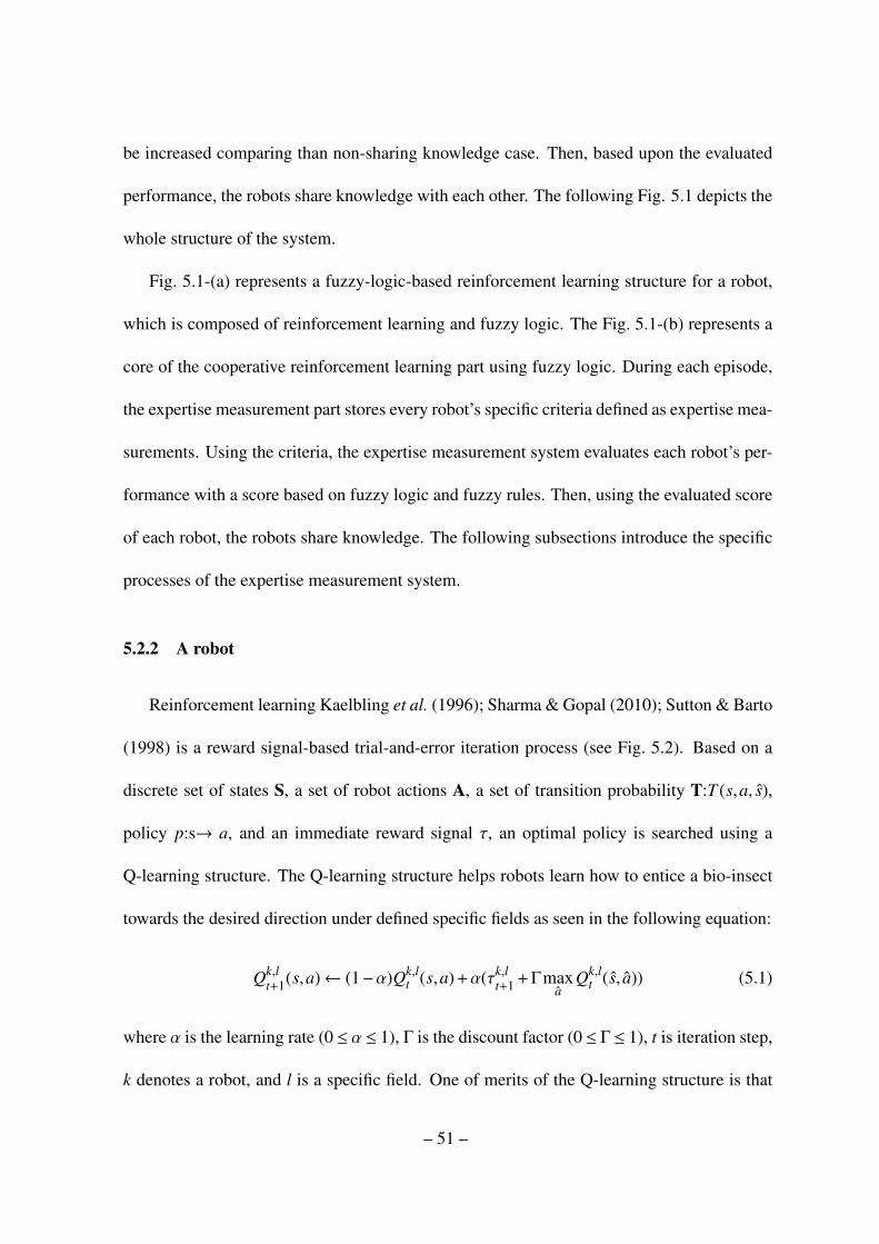
be increased comparing than non-sharing knowledge case. Then, based upon the evaluated
performance, the robots share knowledge with each other. The following Fig. 5.1 depicts the
whole structure of the system.
Fig. 5.1-(a) represents a fuzzy-logic-based reinforcement learning structure for a robot,
which is composed of reinforcement learning and fuzzy logic. The Fig. 5.1-(b) represents a
core of the cooperative reinforcement learning part using fuzzy logic. During each episode,
the expertise measurement part stores every robot’s specific criteria defined as expertise mea-
surements. Using the criteria, the expertise measurement system evaluates each robot’s per-
formance with a score based on fuzzy logic and fuzzy rules. Then, using the evaluated score
of each robot, the robots share knowledge. The following subsections introduce the specific
processes of the expertise measurement system.
5.2.2 A robot
Reinforcement learning Kaelbling et al. (1996); Sharma & Gopal (2010); Sutton & Barto
(1998) is a reward signal-based trial-and-error iteration process (see Fig. 5.2). Based on a
discrete set of states S, a set of robot actions A, a set of transition probability T:T (s,a, s),
policy p:s→ a, and an immediate reward signal τ, an optimal policy is searched using a
Q-learning structure. The Q-learning structure helps robots learn how to entice a bio-insect
towards the desired direction under defined specific fields as seen in the following equation:
Qk,lt+1(s,a)← (1−α)Qk,l
t (s,a) +α(τk,lt+1 +Γmax
aQk,l
t (s, a)) (5.1)
where α is the learning rate (0 ≤ α ≤ 1), Γ is the discount factor (0 ≤ Γ ≤ 1), t is iteration step,
k denotes a robot, and l is a specific field. One of merits of the Q-learning structure is that
– 51 –
it adopts a learning rate α. The learning rate α is a weighting parameter between previously
acquired knowledge and newly acquired knowledge by a reward. When α is near 1, then the
Q-learning structure fully updates newly acquired rewards as part of the exploration process.
Conversely, when α approaches 0, then the structure passes over the newly acquired rewards.
In this case, the structure depends on previous knowledge that a robot has learned as part of
the exploitation process. The value α can be useful for our experiment because the robots
require precise learning knowledge of the complex behavior of bio-insects. If the robots
can control α during the experiment, then performance of the experiment will be enhanced.
In these experiments, we choose the approach where α decreases with an increase in the
number of episodes. Additionally, we adaptively update the specific fields where a robot is
an expert. Using the evaluated performance of each robot, we know which robot is an expert
in the field. Using an initialized Qk,l(s,a) table, (5.1), the k-th robot updates its own table
using the calculated immediate reward at the current state s by the selected action a within a
specific field l.
To understand the behavior of a bio-insect as a result of a given action, we apply a fuzzy
logic to generate rewards for the behavior of a bio-insect, because the fuzzy logic is a good
approach for understanding an imprecise environment, such as understanding emotion of
human behavior Salmeron (2012) and human mind Nikravesh (2008). When the k-th robot
recognizes the current state, then, with a possible set of actions A, it chooses an action a
in the current state s. After the action is executed, the reaction information, including the
variation in distance ∆dbt between the sub-goal point for the b-th bio-insect and the b-th bio-
insect and the variation in distance ∆ekt between the b-th bio-insect and the k-th robot, is
– 52 –
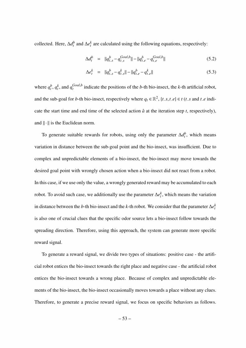
collected. Here, ∆dbt and ∆ek
t are calculated using the following equations, respectively:
∆dbt = ‖qb
t s−qGoal,bt s ‖− ‖qb
t e−qGoal,bt e ‖ (5.2)
∆ekt = ‖qb
t s−qkt s‖− ‖q
bt e−qk
t e‖ (5.3)
where qbt , qk
t , and qGoal,bt indicate the positions of the b-th bio-insect, the k-th artificial robot,
and the sub-goal for b-th bio-insect, respectively where qt ∈ R2, {t s, t e} ∈ t (t s and t e indi-
cate the start time and end time of the selected action a at the iteration step t, respectively),
and ‖ · ‖ is the Euclidean norm.
To generate suitable rewards for robots, using only the parameter ∆dbt , which means
variation in distance between the sub-goal point and the bio-insect, was insufficient. Due to
complex and unpredictable elements of a bio-insect, the bio-insect may move towards the
desired goal point with wrongly chosen action when a bio-insect did not react from a robot.
In this case, if we use only the value, a wrongly generated reward may be accumulated to each
robot. To avoid such case, we additionally use the parameter ∆ekt , which means the variation
in distance between the b-th bio-insect and the k-th robot. We consider that the parameter ∆ekt
is also one of crucial clues that the specific odor source lets a bio-insect follow towards the
spreading direction. Therefore, using this approach, the system can generate more specific
reward signal.
To generate a reward signal, we divide two types of situations: positive case - the artifi-
cial robot entices the bio-insect towards the right place and negative case - the artificial robot
entices the bio-insect towards a wrong place. Because of complex and unpredictable ele-
ments of the bio-insect, the bio-insect occasionally moves towards a place without any clues.
Therefore, to generate a precise reward signal, we focus on specific behaviors as follows.
– 53 –

Positive case: If the bio-insect followed the artificial robot (∆ekt is VG) and the artificial
robot enticed the bio-insect towards the right place (∆dbt is VG), then we consider that this is
a very good case A. Negative Cases: If the bio-insect did not follow the artificial robot (∆ekt is
VB or BD) and the artificial robot moved the bio-insect towards the right place (∆dkt is VG),
then we consider that this is a very bad case E. If the bio-insect followed the artificial robot
(∆ekt is VG or GD) and the artificial robot enticed the bio-insect towards a wrong place, then
we consider that this is very bad case E. The other rules have considered as meaningless
cases C and the rules that are slightly related with above positive and negative cases have
been classified as B or D. Based on the above regulation for generating rewards, detailed
fuzzy rules are developed as shown in Table 5.2.
Based on the fuzzy rules described in Table 5.1, the input variables ∆et and ∆dt are
changed by the following membership functions (5.4) and (5.5) as depicted in Fig. 5.3 - (a)
and (b).
µd = {VGd,GDd,NMd,PRd,VPd} (5.4)
µe = {VGe,GDe,NMe,PRe,VPe} (5.5)
µoutput = {A,B,C,D,E} (5.6)
where VG, GD, NM, PR, and VP indicate very good, good, normal, poor, and very poor,
respectively. In the fuzzy sets, VG, GD, NM, BD, VB, A, B, C, D, and E represent each
fuzzy membership function, and input variables are changed by linguistic process. Next,
the calculated values ∆dbt and ∆ek
t are converted by a fuzzification process using the defined
fuzzy sets as depicted in Fig. 5.3 - (a) and (b).
After the fuzzification process, the converted values are calculated using (5.7) and (5.8)
– 54 –

with a max-min composition process. Then using the fuzzy rules shown in Table 5.1, all of
the values are expressed into output fuzzy sets as depicted in Fig.5.3 - (c) using (5.8). All the
outputs are combined into the aggregation of output fuzzy sets as union process in set theory.
µi = min[min[µid(∆db
t ),µie(∆ek
t )],µioutput] (5.7)
µo(u) =⋃25
i=1µi (5.8)
where parameter i represents number of fuzzy rules and k denotes robot.
An immediate reward is calculated using the center of mass method as follows:
τk,lt+1 =
∫uµo(u)du∫µo(u)du
(5.9)
Based on the reinforcement learning structure, the fuzzy logic generates a reward signal
τk,lt+1 for the k-th robot from the collected reaction of the bio-insect in specific field l. Then
using the reward, a robot updates the Qk,l(s,a) table and tries to optimize the Q-table as
knowledge.
5.2.3 Expertise measurement
When we examine the performance of each robot, various indexes can be used as mea-
surements. In our structure, we choose the following three measurements: average reward,
positive average reward, and percentage of positive rewards. Average reward is calculated as
follows:
τk,lavg =
∑Mk,l
t=1 τk,lt+1
Mk,l (5.10)
where Mk,l is the number of iterations for k-th robot in the specific field l.
– 55 –
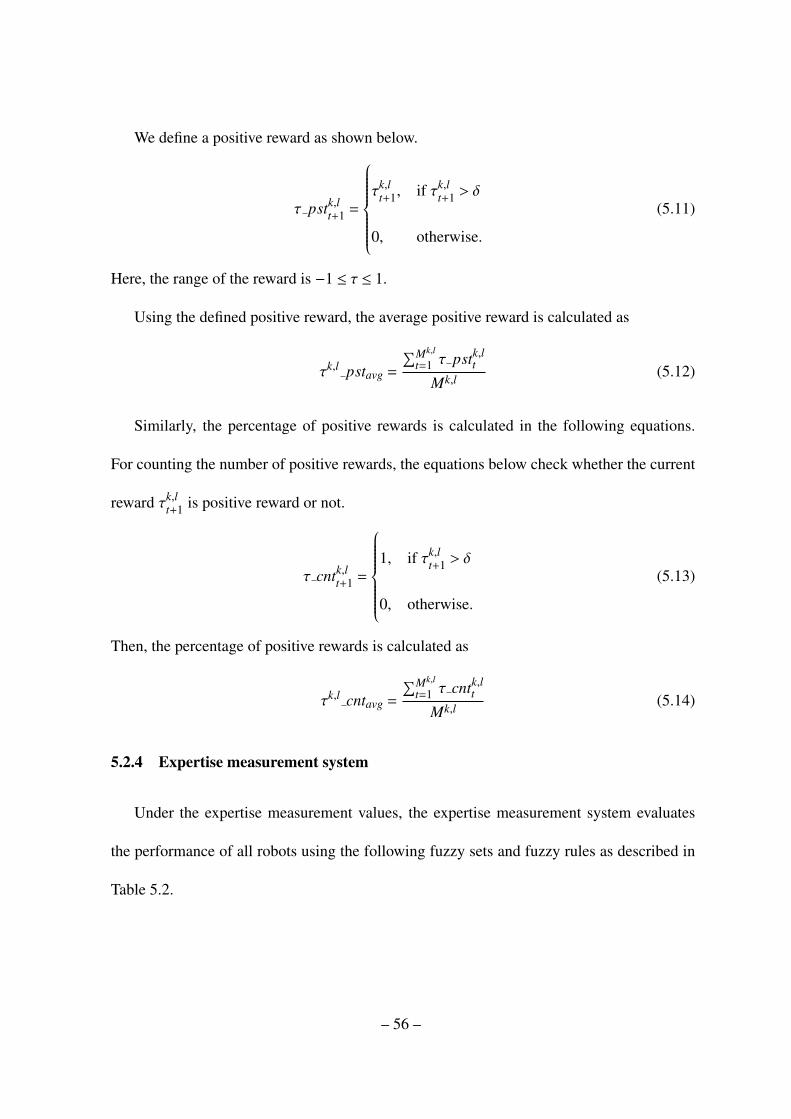
We define a positive reward as shown below.
τ pstk,lt+1 =
τk,l
t+1, if τk,lt+1 > δ
0, otherwise.
(5.11)
Here, the range of the reward is −1 ≤ τ ≤ 1.
Using the defined positive reward, the average positive reward is calculated as
τk,l pstavg =
∑Mk,l
t=1 τ pstk,lt
Mk,l (5.12)
Similarly, the percentage of positive rewards is calculated in the following equations.
For counting the number of positive rewards, the equations below check whether the current
reward τk,lt+1 is positive reward or not.
τ cntk,lt+1 =
1, if τk,l
t+1 > δ
0, otherwise.
(5.13)
Then, the percentage of positive rewards is calculated as
τk,l cntavg =
∑Mk,l
t=1 τ cntk,lt
Mk,l (5.14)
5.2.4 Expertise measurement system
Under the expertise measurement values, the expertise measurement system evaluates
the performance of all robots using the following fuzzy sets and fuzzy rules as described in
Table 5.2.
– 56 –
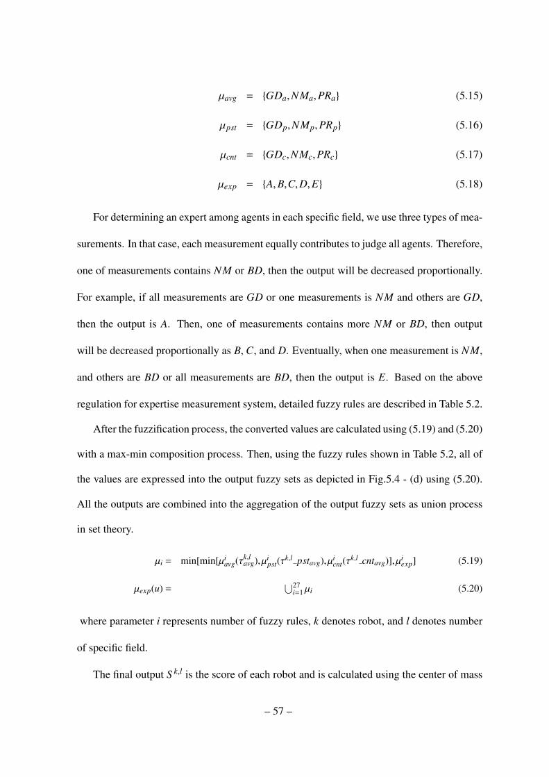
µavg = {GDa,NMa,PRa} (5.15)
µpst = {GDp,NMp,PRp} (5.16)
µcnt = {GDc,NMc,PRc} (5.17)
µexp = {A,B,C,D,E} (5.18)
For determining an expert among agents in each specific field, we use three types of mea-
surements. In that case, each measurement equally contributes to judge all agents. Therefore,
one of measurements contains NM or BD, then the output will be decreased proportionally.
For example, if all measurements are GD or one measurements is NM and others are GD,
then the output is A. Then, one of measurements contains more NM or BD, then output
will be decreased proportionally as B, C, and D. Eventually, when one measurement is NM,
and others are BD or all measurements are BD, then the output is E. Based on the above
regulation for expertise measurement system, detailed fuzzy rules are described in Table 5.2.
After the fuzzification process, the converted values are calculated using (5.19) and (5.20)
with a max-min composition process. Then, using the fuzzy rules shown in Table 5.2, all of
the values are expressed into the output fuzzy sets as depicted in Fig.5.4 - (d) using (5.20).
All the outputs are combined into the aggregation of the output fuzzy sets as union process
in set theory.
µi = min[min[µiavg(τk,l
avg),µipst(τ
k,l pstavg),µicnt(τ
k,l cntavg)],µiexp] (5.19)
µexp(u) =⋃27
i=1µi (5.20)
where parameter i represents number of fuzzy rules, k denotes robot, and l denotes number
of specific field.
The final output S k,l is the score of each robot and is calculated using the center of mass
– 57 –
method:
S k,l =
∫uµexp(u)du∫µexp(u)du
(5.21)
Then, knowledge of each robot is merged as
S l←
N∑k=1
S k,l (5.22)
where N is the number of robots and k denotes a robot k ∈ 1, · · · ,N
Finally, all robots have the shared knowledge as follows:
Ql←
N∑k=1
S k,l
S l ·Qk,l (5.23)
The whole procedures of the fuzzy logic-based expertise measurement system for coop-
erative reinforcement learning are described in the algorithms 4 and 5. In the algorithms,
B denotes the number of bio-insects b ∈ {1, · · · ,B}, L denotes the number of specific fields
l ∈ {1, · · · ,L}, N denotes the number of robots k ∈ {1, · · · ,N}, and Mk,l denotes the number of
iterations of the k-th robot in specific field l.
5.2.5 Comments on reinforcement learning approaches
From literature search, we find several different reinforcement learning approaches as
described in Chapter 1. In order to move the bio-insect towards a given goal point, the robots
need to achieve a common goal together because the robots are supposed to entice the bio-
insect. Therefore, Leng & Lim (2011), Tangamchit et al. (2002), Wang & de Silva (2006),
and Wang & de Silva (2008) may be utilized in our task. On the other hand, Tan (1993) and
Littman (1994) can not be used because they try to achieve opposite goals.
– 58 –
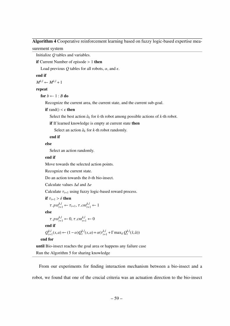
Algorithm 4 Cooperative reinforcement learning based on fuzzy logic-based expertise mea-
surement systemInitialize Q tables and variables.
if Current Number of episode > 1 thenLoad previous Q tables for all robots, α, and ε.
end ifMk,l← Mk,l + 1
repeatfor b← 1 : B do
Recognize the current area, the current state, and the current sub-goal.
if rand() < ε thenSelect the best action ak for k-th robot among possible actions of k-th robot.
if If learned knowledge is empty at current state thenSelect an action ak for k-th robot randomly.
end ifelse
Select an action randomly.
end ifMove towards the selected action points.
Recognize the current state.
Do an action towards the b-th bio-insect.
Calculate values ∆d and ∆e
Calculate τt+1 using fuzzy logic-based reward process.
if τt+1 > δ thenτ pstk,l
t+1← τt+1, τ cntk,lt+1← 1
elseτ pstk,l
t+1← 0, τ cntk,lt+1← 0
end ifQk,l
t+1(s,a)← (1−α)Qk,lt (s,a) +α(τk,l
t+1 +Γmaxa Qk,lt (s, a))
end foruntil Bio-insect reaches the goal area or happens any failure case
Run the Algorithm 5 for sharing knowledge
From our experiments for finding interaction mechanism between a bio-insect and a
robot, we found that one of the crucial criteria was an actuation direction to the bio-insect
– 59 –
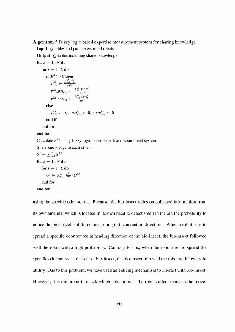
Algorithm 5 Fuzzy logic-based expertise measurement system for sharing knowledgeInput: Q-tables and parameters of all robots
Output: Q-tables including shared knowledge
for k← 1 : N dofor l← 1 : L do
if Mk,l > 0 thenτk,l
avg←
∑Mt=1 τ
k,lt+1
Mk,l
τk,l pstavg←∑M
t=1 τ pstk,ltMk,l
τk,l cntavg←∑M
t=1 τ cntk,ltMk,l
elseτk,l
avg← 0, τ pstk,lavg← 0, τ cntk,l
avg← 0
end ifend for
end forCalculate S k,l using fuzzy logic-based expertise measurement system.
Share knowledge to each other.
S l←∑N
k=1 S k,l
for k← 1 : N dofor l← 1 : L do
Ql←∑N
k=1S k,l
S l ·Qk,l
end forend for
using the specific odor source. Because, the bio-insect relies on collected information from
its own antenna, which is located in its own head to detect smell in the air, the probability to
entice the bio-insect is different according to the actuation directions. When a robot tries to
spread a specific odor source at heading direction of the bio-insect, the bio-insect followed
well the robot with a high probability. Contrary to this, when the robot tries to spread the
specific odor source at the rear of bio-insect, the bio-insect followed the robot with low prob-
ability. Due to this problem, we have used an enticing mechanism to interact with bio-insect.
However, it is important to check which actuations of the robots affect more on the move-
– 60 –
ment of the bio-insect. For example, if two robots locate at the heading side and the rear
side of the bio-insect, then since the heading direction of the bio-insect is right direction that
robots need to entice, the bio-insect only follows a robot located on heading side with a high
probability. However, in that case, even though the bio-insect follows a robot located on
heading direction, two robots (robots locating at the heading side and rear side) will receive
same positive reward since the bio-insect was actuated towards the desired direction. Due
to this problem, in achieving a common goal, the multiple robots may get some problems
in finding the right actions. To handle this problem, in the fuzzy-logic-based expertise mea-
surement system that was introduced in previous sub-sections, each robot only tries to entice
a bio-insect at a chosen action point, and each agent receives a reward and records achieved
performance by expertise measurement. After an episode has been completed, the robots
share knowledge based on own recorded performance using expertise measurement system.
Then, in the next episode, the robots will entice the bio-insect based on shared knowledge.
5.3 Experiment
5.3.1 Experimental setup
As an interaction mechanism between a bio-insect and an artificial robot, we find a spe-
cific odor source that helps the bio-insect follow the artificial robot in Chapter 3. Using
the interaction mechanism, each robot learns how to entice a bio-insect towards the desired
goal point under cooperative manner. To realize this concept, we conduct the following two
experiments using a bio-insect and two artificial robots: Experiment A - without sharing
knowledge as a control group and Experiment B - with sharing knowledge as a experimental
– 61 –

Table 5.1: 25 Fuzzy rules
F01: IF (∆dbt is VGd) and (∆ek
t is VGe), THEN Output is A
F02: IF (∆dbt is VGd) and (∆ek
t is GDe), THEN Output is B
F03: IF (∆dbt is VGd) and (∆ek
t is NMe), THEN Output is C
F04: IF (∆dbt is VGd) and (∆ek
t is BDe), THEN Output is D
F05: IF (∆dbt is VGd) and (∆ek
t is VBe), THEN Output is E
F06: IF (∆dbt is GDd) and (∆ek
t is VGe), THEN Output is B
F07: IF (∆dbt is GDd) and (∆ek
t is GDe), THEN Output is C
F08: IF (∆dbt is GDd) and (∆ek
t is NMe), THEN Output is C
F09: IF (∆dbt is GDd) and (∆ek
t is BDe), THEN Output is D
F10: IF (∆dbt is GDd) and (∆ek
t is VBe), THEN Output is E
F11: IF (∆dbt is NMd) and (∆ek
t is VGe), THEN Output is C
F12: IF (∆dbt is NMd) and (∆ek
t is GDe), THEN Output is C
F13: IF (∆dbt is NMd) and (∆ek
t is NMe), THEN Output is C
F14: IF (∆dbt is NMd) and (∆ek
t is BDe), THEN Output is C
F15: IF (∆dbt is NMd) and (∆ek
t is VBe), THEN Output is C
F16: IF (∆dbt is BDd) and (∆ek
t is VGe), THEN Output is E
F17: IF (∆dbt is BDd) and (∆ek
t is GDe), THEN Output is D
F18: IF (∆dbt is BDd) and (∆ek
t is NMe), THEN Output is C
F19: IF (∆dbt is BDd) and (∆ek
t is BDe), THEN Output is C
F20: IF (∆dbt is BDd) and (∆ek
t is VBe), THEN Output is C
F21: IF (∆dbt is VBd) and (∆ek
t is VGe), THEN Output is E
F22: IF (∆dbt is VBd) and (∆ek
t is GDe), THEN Output is D
F23: IF (∆dbt is VBd) and (∆ek
t is NMe), THEN Output is C
F24: IF (∆dbt is VBd) and (∆ek
t is BDe), THEN Output is C
F25: IF (∆dbt is VBd) and (∆ek
t is VBe), THEN Output is C
– 62 –

group using the fuzzy logic based expertise measurement system as described in previous
section to measure effect of sharing knowledge.
In examining the performance of the cooperative reinforcement learning, we consider
that it is more favorable to increase the number of artificial robots. Because, when the num-
ber of artificial robots is increased, then the number of clues for obtaining knowledge is also
increased by sharing the obtained knowledge. It means that the total learning time can be
reduced if they share knowledge efficiently. However, in our experiments, only two robots
were utilized for single bio-insect due to limited space around the bio-insect. In examining
the performance of the cooperative reinforcement learning, we build the following experi-
mental platforms illustrated in Fig. 5.5 for Experiments. As shown in Fig.5.5-(a) and (c),
robot 1 and robot 2 work as a group for bio-insect 1. In the Experiment A, individual agents
1 and 2 perform to entice the bio-insect together without sharing knowledge. The Experi-
ment B focuses on sharing knowledge between the two artificial robots. In the experiments,
the robot 1 and robot 2 try to entice the bio-insect 1 towards a given sub-goal point while
avoiding artificial walls and common restricted areas. Each sub-goal point is given by Al-
gorithm 6. All sub-goal points and areas are illustrated in Fig. 5.5-(b). Especially, after the
robots have conducted the experiment at every episode, they share their knowledge using the
fuzzy logic-based expertise measurement systems only in the Experiment B. Then, in the
next episode, the robots try to entice the bio-insect using the shared knowledge.
To recognize the current state among the bio-insects and robots, we define states that
consist of a heading angle and a goal direction for the bio-insect, as illustrated in Fig. 5.6-(a).
The heading angle and the goal direction are divided into eight equal parts, each separated by
– 63 –

Algorithm 6 Recognizing the current area and selecting a sub-goal for a bio-insectSub goals for Bio-insect: #2→ #3→ #4 (final goal)
Input: Current area and current sub-goal of the bio-insect
Output: Sub-goal of the bio-insect
if Current area , Final goal area #4 thenChoose a next sub-goal on current area.
elseChoose a final sub-goal #4.
end if
45◦ with drawn dotted lines in Fig. 5.6-(a). To entice the bio-insect, the number of actuation
points is illustrated in Fig. 5.6-(b). The action points consist of three different distance ranges
as d1, d2, and d3 and eight different directions separated by 45◦. At chosen points among the
action points, robots spread a specific odor source towards the bio-insect. To avoid collision,
the robots move around a related bio-insect at a restricted distance range among them.
5.3.2 Experimental results
In this experiment, we use the following parameters: α= 0.85, Γ = 0.95, ε = 0.3, Γe = 0.6,
εe = 0.03, d1 = 23cm, d2 = 26cm, and d3 = 29cm. The parameters Γ and ε are decreased by
0.008 and 0.02 per each episode step e, respectively.
Γ(e + 1) =
Γ(e)−∆Γ, if Γ(e) > Γe
Γe, otherwise
(5.24)
ε(e + 1) =
ε(e)−∆ε, if ε(e) > εe
εe, otherwise
(5.25)
– 64 –

where ∆Γ=0.008 and ∆ε=0.02. If either Γ or ε reaches a defined minimum value, then the
value becomes invariable under the next episode variations. After executing the experiments,
we obtain the following results1.
Every beginning of the experiment, we need to check reactivity of the chosen bio-insect.
If the reactivity of the bio-insect is sufficient to conduct the experiment, then we choose the
bio-insect for the experiment. We conduct the experiment for seven days and do not exceed
the predefined maximum number of repetitions for a bio-insect and maximum duration per
episode during the experiment. Here, the maximum number of repetitions is 4 and the maxi-
mum duration per episode is 15 minutes. After executing a number of experiments, we have
obtained the following experimental results as shown in the Table 5.3. Both experiments
have been performed 30 times with 4 bio-insects. The bio-insects are chosen by a given nu-
merical order and are swapped out when they become exhausted or demonstrate incompliant
reactions with the given actions of a robot.
In Experiment A, the robots achieves 30.0% success rate using the 4 bio-insects as shown
in Fig. 5.7 and as described in Table 5.4. From the first episode, performance of the entic-
ing ability increases with learning process as shown in the Fig. 5.7. The episode No. 27
recognizes as the shortest iterations (12 times) and shorted lap time (160 sec) among whole
episodes in Experiment A. As a control group, the robots do not share knowledge after
finishing current episode domains. Each individual robot only learns knowledge from the
experience.
In Experiment B, the robots achieves 53.3% success rate using 4 bio-insects as shown in
1Reader can view all experimental movie clips by visiting the web site: http://dcas.gist.ac.kr/bridscrl
– 65 –
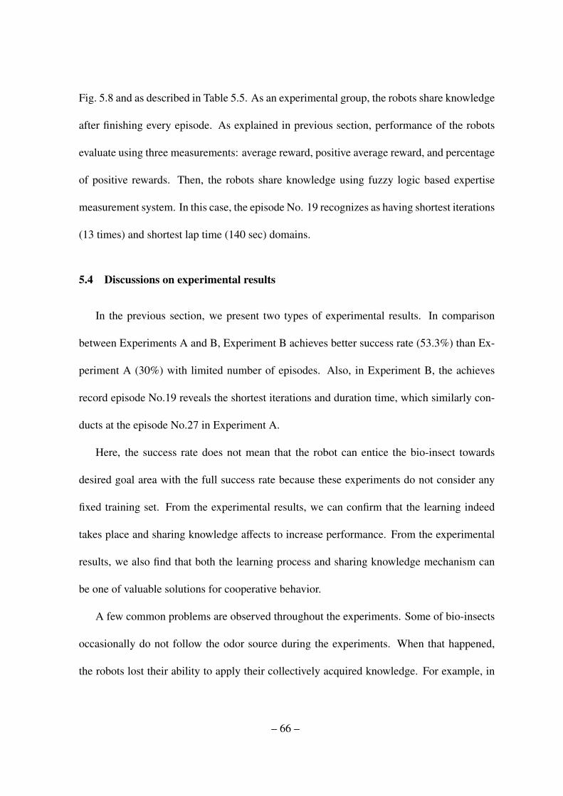
Fig. 5.8 and as described in Table 5.5. As an experimental group, the robots share knowledge
after finishing every episode. As explained in previous section, performance of the robots
evaluate using three measurements: average reward, positive average reward, and percentage
of positive rewards. Then, the robots share knowledge using fuzzy logic based expertise
measurement system. In this case, the episode No. 19 recognizes as having shortest iterations
(13 times) and shortest lap time (140 sec) domains.
5.4 Discussions on experimental results
In the previous section, we present two types of experimental results. In comparison
between Experiments A and B, Experiment B achieves better success rate (53.3%) than Ex-
periment A (30%) with limited number of episodes. Also, in Experiment B, the achieves
record episode No.19 reveals the shortest iterations and duration time, which similarly con-
ducts at the episode No.27 in Experiment A.
Here, the success rate does not mean that the robot can entice the bio-insect towards
desired goal area with the full success rate because these experiments do not consider any
fixed training set. From the experimental results, we can confirm that the learning indeed
takes place and sharing knowledge affects to increase performance. From the experimental
results, we also find that both the learning process and sharing knowledge mechanism can
be one of valuable solutions for cooperative behavior.
A few common problems are observed throughout the experiments. Some of bio-insects
occasionally do not follow the odor source during the experiments. When that happened,
the robots lost their ability to apply their collectively acquired knowledge. For example, in
– 66 –
Experiment A, bio-insect 4 does not make success every time. However, in Experiment B,
the bio-insect 4 achieves about 83.3% success rate. When the bio-insects fails to follow the
robots, no patterns or evidence is observed from the result. Additionally, in our previous
experiments using human operator in Chapter 3, we got only 80% success rate. This means
that even human can not fully entice the bio-insect. This effect might come from the con-
dition (physical strength) or unknown other characteristics of individual bio-insect. As seen
in previous experimental results, the bio-insects frequently show complex and unpredictable
behavior. Those problems therefore cause disturbances to the robots’ learning ability, as seen
by the non-convergence of the number of iterations and the time duration with the increasing
numbers of episodes. Also, sometimes, the robots proceed towards the bio-insect in a wrong
direction or place due to a randomly selected action. Consequently, the bio-insect occasion-
ally moves in a wrong direction. Therefore, the number of iterations do not decrease with
the increasing number of episodes. Therefore, if we conduct more experiments with increas-
ing number of episodes, variations in both number of iterations and lap time domain will
frequently happen again due to complex and unpredictable elements of the bio-insect. How-
ever, taking account all the results, we still confirm that sharing knowledge in the experiment
B shows better performance than non-sharing knowledge case in the experiment A.
5.5 Conclusion
In this chapter, we have presented a cooperative reinforcement learning technique using
a fuzzy logic-based expertise measurement system to entice bio-insects towards desired goal
areas. Based upon our obtained results in previous chapter, we have modified the fuzzy rules
– 67 –
and input values to obtain a more precise knowledge to control the movement of the bio-
insects. We have also addressed the fuzzy logic-based expertise measurement system for
sharing knowledge among the robots. We then obtain meaningful experimental results using
two types of experiments. As a control group, the robots entice the bio-insect without sharing
knowledge in Experiment A, and the robots enticed the bio-insect with sharing knowledge
as the second experimental group in Experiment B. In comparison between the Experiments
A and B, Experiment B shows better results than Experiment A, which means that sharing
knowledge using fuzzy-logic-based expertise measurement system is more efficient way for
our task.
– 68 –

Figure 5.1: Structure of cooperative reinforcement learning based on a fuzzy logic-based
expertise measurement system: (a) fuzzy-logic-based reinforcement learning structure for a
robot i. (b) expertise measurement part for sharing knowledge of robots i, j, · · · ,k
– 69 –

Figure 5.2: Structure of reinforcement learning: The structure is composed of two parts; one
is the robot, and the other one is the environment. Based on the recognized state st, the robot
actuates an action towards the environment as at, following which an output is given to the
robot as a reward τt+1. This circulation process makes the robot acquire knowledge under a
trial-and-error iteration process. This learning mechanism is similar to the learning behavior
of animals that possess intelligence.
Figure 5.3: Input fuzzy sets: (a) - distance variation (∆dbt ) as an input and (b) - distance
variation (∆ekt ) as an input and output fuzzy sets: (c) - output
– 70 –
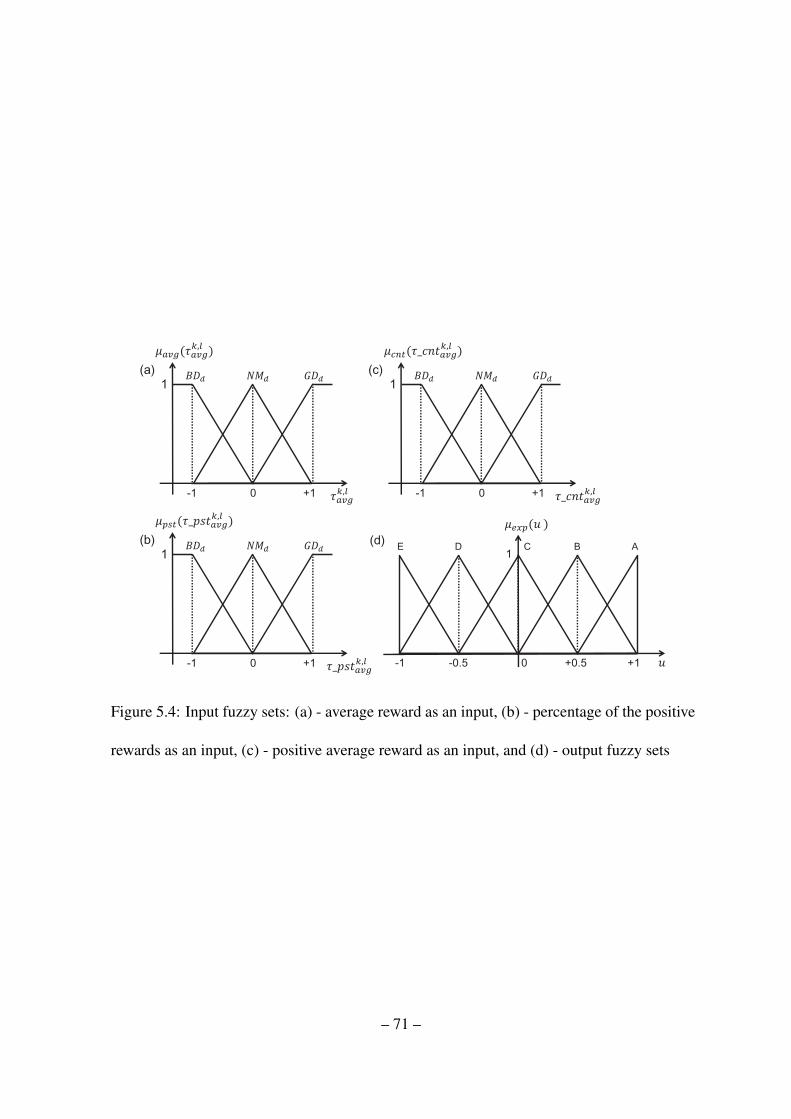
Figure 5.4: Input fuzzy sets: (a) - average reward as an input, (b) - percentage of the positive
rewards as an input, (c) - positive average reward as an input, and (d) - output fuzzy sets
– 71 –
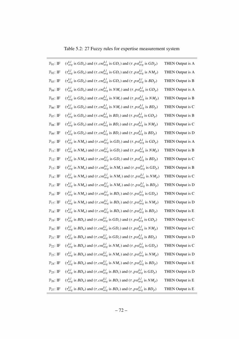
Table 5.2: 27 Fuzzy rules for expertise measurement system
F01: IF (τk,lavg is GDa) and (τ cntk,l
avg is GDc) and (τ pstk,lavg is GDp) THEN Output is A
F02: IF (τk,lavg is GDa) and (τ cntk,l
avg is GDc) and (τ pstk,lavg is NMp) THEN Output is A
F03: IF (τk,lavg is GDa) and (τ cntk,l
avg is GDc) and (τ pstk,lavg is BDp) THEN Output is B
F04: IF (τk,lavg is GDa) and (τ cntk,l
avg is NMc) and (τ pstk,lavg is GDp) THEN Output is A
F05: IF (τk,lavg is GDa) and (τ cntk,l
avg is NMc) and (τ pstk,lavg is NMp) THEN Output is B
F06: IF (τk,lavg is GDa) and (τ cntk,l
avg is NMc) and (τ pstk,lavg is BDp) THEN Output is C
F07: IF (τk,lavg is GDa) and (τ cntk,l
avg is BDc) and (τ pstk,lavg is GDp) THEN Output is B
F08: IF (τk,lavg is GDa) and (τ cntk,l
avg is BDc) and (τ pstk,lavg is NMp) THEN Output is C
F09: IF (τk,lavg is GDa) and (τ cntk,l
avg is BDc) and (τ pstk,lavg is BDp) THEN Output is D
F10: IF (τk,lavg is NMa) and (τ cntk,l
avg is GDc) and (τ pstk,lavg is GDp) THEN Output is A
F11: IF (τk,lavg is NMa) and (τ cntk,l
avg is GDc) and (τ pstk,lavg is NMp) THEN Output is B
F12: IF (τk,lavg is NMa) and (τ cntk,l
avg is GDc) and (τ pstk,lavg is BDp) THEN Output is C
F13: IF (τk,lavg is NMa) and (τ cntk,l
avg is NMc) and (τ pstk,lavg is GDp) THEN Output is B
F14: IF (τk,lavg is NMa) and (τ cntk,l
avg is NMc) and (τ pstk,lavg is NMp) THEN Output is C
F15: IF (τk,lavg is NMa) and (τ cntk,l
avg is NMc) and (τ pstk,lavg is BDp) THEN Output is D
F16: IF (τk,lavg is NMa) and (τ cntk,l
avg is BDc) and (τ pstk,lavg is GDp) THEN Output is C
F17: IF (τk,lavg is NMa) and (τ cntk,l
avg is BDc) and (τ pstk,lavg is NMp) THEN Output is D
F18: IF (τk,lavg is NMa) and (τ cntk,l
avg is BDc) and (τ pstk,lavg is BDp) THEN Output is E
F19: IF (τk,lavg is BDa) and (τ cntk,l
avg is GDc) and (τ pstk,lavg is GDp) THEN Output is C
F20: IF (τk,lavg is BDa) and (τ cntk,l
avg is GDc) and (τ pstk,lavg is NMp) THEN Output is C
F21: IF (τk,lavg is BDa) and (τ cntk,l
avg is GDc) and (τ pstk,lavg is BDp) THEN Output is D
F22: IF (τk,lavg is BDa) and (τ cntk,l
avg is NMc) and (τ pstk,lavg is GDp) THEN Output is C
F23: IF (τk,lavg is BDa) and (τ cntk,l
avg is NMc) and (τ pstk,lavg is NMp) THEN Output is D
F24: IF (τk,lavg is BDa) and (τ cntk,l
avg is NMc) and (τ pstk,lavg is BDp) THEN Output is E
F25: IF (τk,lavg is BDa) and (τ cntk,l
avg is BDc) and (τ pstk,lavg is GDp) THEN Output is D
F26: IF (τk,lavg is BDa) and (τ cntk,l
avg is BDc) and (τ pstk,lavg is NMp) THEN Output is E
F27: IF (τk,lavg is BDa) and (τ cntk,l
avg is BDc) and (τ pstk,lavg is BDp) THEN Output is E
– 72 –

Figure 5.5: Experimental platform for experiments: (a) - designed state for recognizing the
current state of location (b) - defined areas and sub goal points, and (c) - photograph of the
experimental platform
– 73 –

Actuation Point
(a)
(b)
Figure 5.6: Designed states: (a) - designed states for recognizing the current state and (b) -
related actuation points for robots
– 74 –
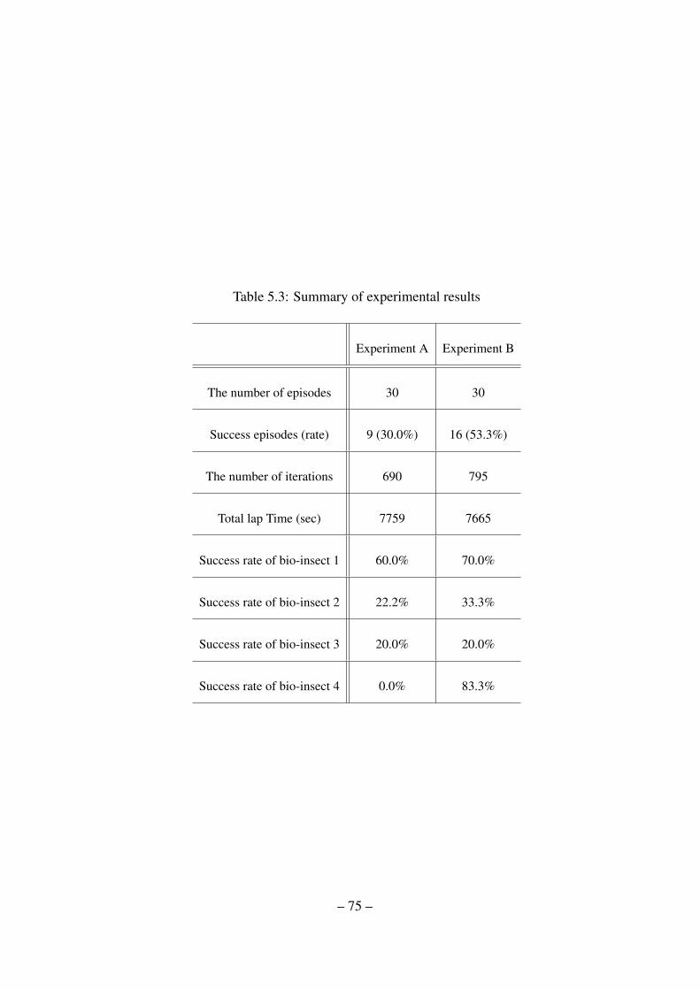
Table 5.3: Summary of experimental results
Experiment A Experiment B
The number of episodes 30 30
Success episodes (rate) 9 (30.0%) 16 (53.3%)
The number of iterations 690 795
Total lap Time (sec) 7759 7665
Success rate of bio-insect 1 60.0% 70.0%
Success rate of bio-insect 2 22.2% 33.3%
Success rate of bio-insect 3 20.0% 20.0%
Success rate of bio-insect 4 0.0% 83.3%
– 75 –

0
10
20
30
40
50
60
70
0 5 10 15 20 25 30
0
100
200
300
400
500
600
700
800
Nu
mb
er
of
Ite
rati
on
s
La
p T
ime
(se
c)Number of Episodes
Experimental Results
Iteration of Success CaseLab Time of Success Case
Iteration of Failure CaseLab Time of Failure Case
Figure 5.7: Results of experiment A - In this figure, four types of results are indicated:
Successful cases of iterations, lap time (drawn with lines), failure cases of iterations, and lap
time
– 76 –
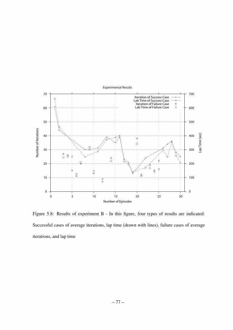
0
10
20
30
40
50
60
70
0 5 10 15 20 25 30
0
100
200
300
400
500
600
700
Nu
mb
er
of
Ite
rati
on
s
La
p T
ime
(se
c)Number of Episodes
Experimental Results
Iteration of Success CaseLab Time of Success Case
Iteration of Failure CaseLab Time of Failure Case
Figure 5.8: Results of experiment B - In this figure, four types of results are indicated:
Successful cases of average iterations, lap time (drawn with lines), failure cases of average
iterations, and lap time
– 77 –
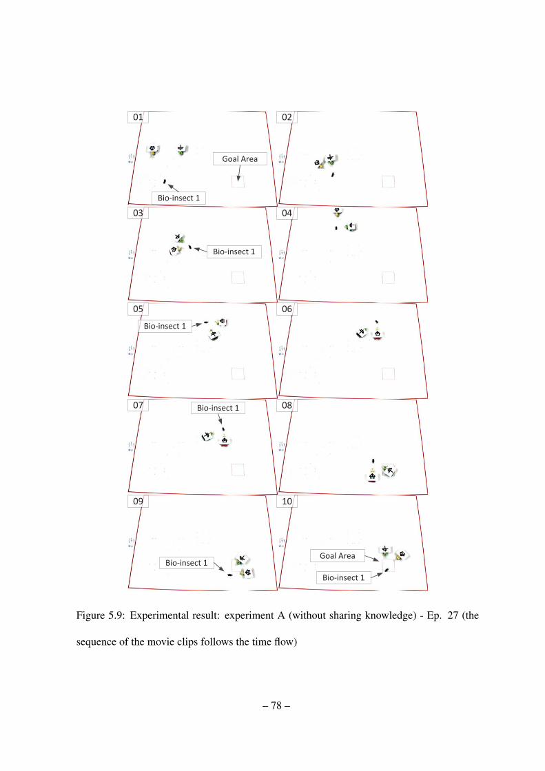
01 02
03 04
05 06
07 08
09 10
Bio-insect 1
Bio-insect 1
Bio-insect 1
Bio-insect 1
Bio-insect 1
Goal Area
Goal Area
Bio-insect 1
Figure 5.9: Experimental result: experiment A (without sharing knowledge) - Ep. 27 (the
sequence of the movie clips follows the time flow)
– 78 –
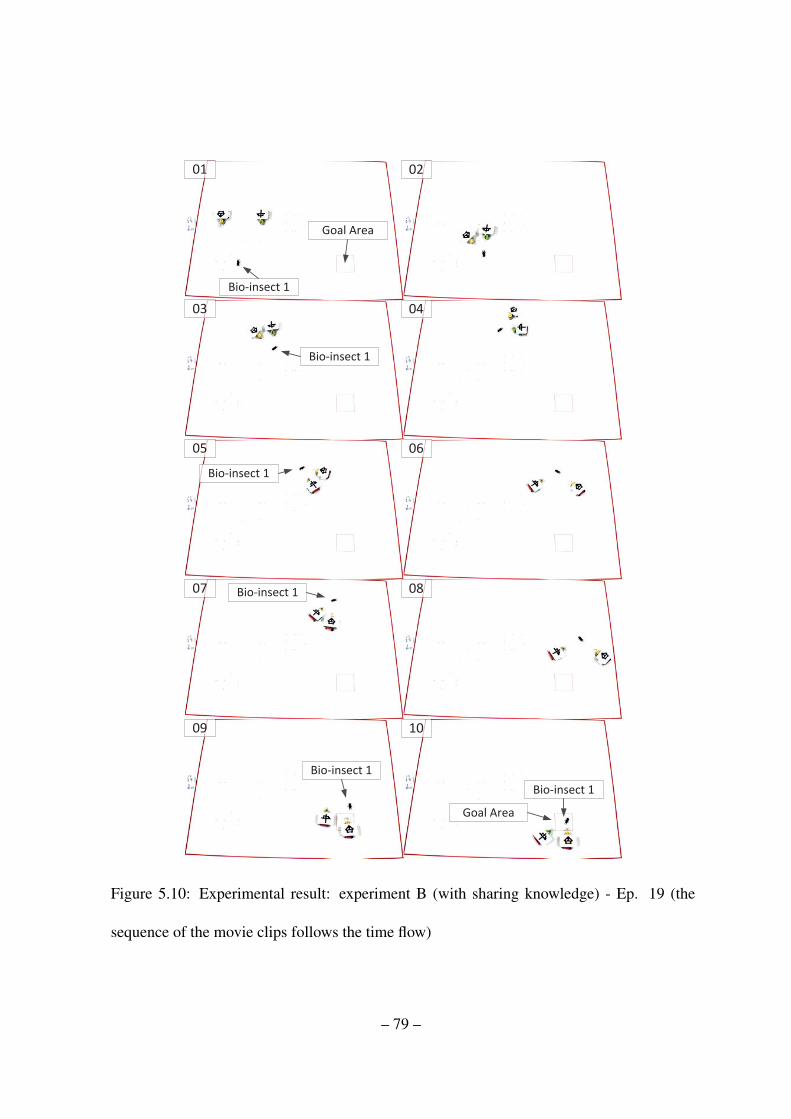
01 02
03 04
05 06
07 08
09 10
Bio-insect 1
Bio-insect 1
Bio-insect 1
Bio-insect 1
Bio-insect 1
Goal Area
Goal Area
Bio-insect 1
Figure 5.10: Experimental result: experiment B (with sharing knowledge) - Ep. 19 (the
sequence of the movie clips follows the time flow)
– 79 –

Table 5.4: Detailed experimental results for experiment A
Episode Iterations Lap Time(sec) Insect No. Result
1 66 710 1 Success
2 11 132 1 Failure
3 39 401 1 Failure
4 15 237 2 Failure
5 44 560 2 Success
6 16 190 2 Failure
7 28 441 3 Success
8 18 176 4 Failure
9 40 353 4 Failure
10 20 205 4 Failure
11 28 303 1 Success
12 37 402 1 Success
13 26 263 1 Success
14 49 609 1 Failure
15 34 343 2 Success
16 28 342 2 Failure
17 6 59 2 Failure
18 15 134 2 Failure
19 20 215 3 Failure
20 9 77 3 Failure
21 13 137 3 Failure
22 10 103 3 Failure
23 11 101 4 Failure
24 14 149 4 Failure
25 10 101 4 Failure
26 16 185 1 Success
27 12 160 1 Success
28 11 119 1 Failure
29 37 462 2 Failure
30 7 90 2 Failure
– 80 –
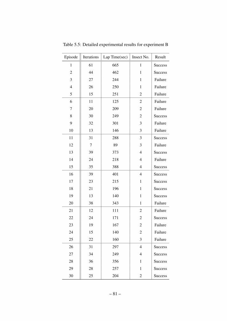
Table 5.5: Detailed experimental results for experiment B
Episode Iterations Lap Time(sec) Insect No. Result
1 61 665 1 Success
2 44 462 1 Success
3 27 244 1 Failure
4 26 250 1 Failure
5 15 251 2 Failure
6 11 125 2 Failure
7 20 209 2 Failure
8 30 249 2 Success
9 32 301 3 Failure
10 13 146 3 Failure
11 31 288 3 Success
12 7 89 3 Failure
13 39 373 4 Success
14 24 218 4 Failure
15 35 388 4 Success
16 39 401 4 Success
17 23 215 1 Success
18 21 196 1 Success
19 13 140 1 Success
20 38 343 1 Failure
21 12 111 2 Failure
22 24 171 2 Success
23 19 167 2 Failure
24 15 140 2 Failure
25 22 160 3 Failure
26 31 297 4 Success
27 34 249 4 Success
28 36 356 1 Success
29 28 257 1 Success
30 25 204 2 Success
– 81 –

Chapter 6
Hierarchical reinforcement learning based inter-
action between bio-insect and artificial robot
6.1 Introduction
In this chapter, we propose hierarchical reinforcement learning based interaction between
bio-insect and artificial robot. In the previous experiments, we have assumed that the position
and heading angle of the bio-insect are exactly known by a camera, which is attached on the
top of the platform. Also, the robot has only needed to entice the each desired goal place on
the each defined area. However, in this paper, the robot requires to find the bio-insect using a
camera, which is attached on the robot and to recognize the position and heading angle of the
bio-insect. Therefore, the robot needs to know position of the bio-insect at every time and
tries to entice the predefined trajectory. So, the robot uses only locally-obtained knowledge
to entice a bio-insect, which demands a more advanced learning ability. At first, it needs to
explore to find the bio-insect; then, using the obtained position and heading angle, the robot
learns how to entice the bio-insect into following closely along the given trajectory. We
consider that the current experimental results are more realistic than previous experimental
results because the robot mainly relies on the attached camera of the robot like animal. Also,
previous experiments have focused on learning how to entice the bio-insect towards desired
– 82 –
direction using fuzzy-logic-based reinforcement learning and fuzzy-logic-based expertise
measurement system for cooperative learning. In this section, the learning structures try to
learn how to make predefined behaviors of a bio-insect and which behavior is necessary to
make the bio-insect follow the given trajectory using hierarchical reinforcement learning.
In the hierarchical reinforcement learning, low level structures focus on learning methods
to make the predefined behaviors of the bio-insect and a high level structure learns which
behavior is necessary to make the robot follow the given trajectory.
6.2 Methodologies
To setup an experimental environment, we built the experimental platform as illustrated
in Fig. 6.1-(b) and (d). The size of the experimental platform is 196 cm x 147cm, and it
contains a camera (1024x768 resolutions) and a computer. Fig. 6.1-(c) shows the shape of
the desired trajectory. To entice the bio-insect along the trajectory, the artificial robot needs
to know where the current location is. In the platform, a camera attached to the ceiling
faced to the experimental platform detects a landmark upon the artificial robot. Here, the
artificial robot only receives its own position from the computer; it does not receive the
position of the bio-insect. A wireless camera attached on the artificial robot detects the bio-
insect and computes the position and heading information of the bio-insect with respect to
the robot. The wireless camera sends the real images to the computer and the computer
recognizes the bio-insect based on the designed recognition algorithm. The artificial robot is
fully controlled by the computer through the wireless signal. The computer conducts all the
image processing, data storage of the learned data, and control of the artificial robot.
– 83 –

Figure 6.1: Experimental setup. (a) the bio-insects (stag beetles - Dorcus titanus castani-
color(left) and Dorcus hopei binodulosus(right). (b) artificial robot - It contains a wireless
camera to detect the bio-insect, two servo-motors to track the bio-insect using the wireless
camera, two air pump motors to spread odor source, an e-puck robot to move onto specific
positions, a landmark to detect the position of the artificial robot, and a Li-Po battery. (c)
experimental platform and the shape of the given trajectory. (d) experimental environment
- To entice the bio-insect on the trajectory, the artificial robot needs position data. In the
hardware platform, a camera is attached to the ceiling faced to the experimental platform,
and the camera detects a landmark installed on the artificial robot.
As a candidate of the bio-insect, we choose two types of living stag beetles: Dorcus
titanus castanicolor (left) and Dorcus hopei binodulosus (right) as shown in Fig. 6.1-(a). The
– 84 –
bio-insects have a physical strength strong enough to endure a number of experiments, a good
mobility over flat surface and around 2-3 years life span. To find interaction mechanisms
between the bio-insect and the artificial robot, we fulfilled a number of experiments using
various stimulus such as light, vibration, air flow, movement of robot, physical contact with
the robot, and sound. The reaction from the bio-insect was not too strong to achieve our goal.
However, we observed that the bio-insect mainly uses three groups of antennas attached on
its head to monitor environment. After conducting experiments, we fortunately found that
the bio-insect strongly reacts to the specific odor source from sawdust of its own habitat Son
& Ahn (2014).
The main task of the robot is to learn the behaviors of the insect in order to entice the bio-
insect towards desired direction. To perform such task, two air pump motors and two bottles
containing the specific odor sources are equipped to the robot. The specific odor sources are
spread by the equipment to the air through a duct. The wireless camera mounted on the two
servo-motors watches and tracks the bio-insect for recognizing and tracking it in real time.
The air pump motors and servo-motors are controlled by Atmega 128 microprocessor. The
landmark marked on the top of the artificial robot is used to compute the current position and
heading angle of the artificial robot. A 7.4v Li-Po battery supplies electricity to the whole
robot systems.
6.3 Experiment
At the beginning, the artificial robot does not know where the bio-insect is. At the current
position, the artificial robot tries to find the bio-insect by rotating its heading and by increas-
– 85 –
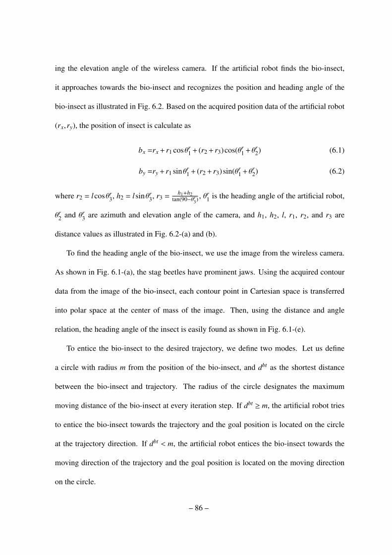
ing the elevation angle of the wireless camera. If the artificial robot finds the bio-insect,
it approaches towards the bio-insect and recognizes the position and heading angle of the
bio-insect as illustrated in Fig. 6.2. Based on the acquired position data of the artificial robot
(rx,ry), the position of insect is calculate as
bx =rx + r1 cosθr1 + (r2 + r3)cos(θr
1 + θr2) (6.1)
by =ry + r1 sinθr1 + (r2 + r3) sin(θr
1 + θr2) (6.2)
where r2 = lcosθr3, h2 = lsinθr
3, r3 =h1+h2
tan(90−θr3) , θ
r1 is the heading angle of the artificial robot,
θr2 and θr
3 are azimuth and elevation angle of the camera, and h1, h2, l, r1, r2, and r3 are
distance values as illustrated in Fig. 6.2-(a) and (b).
To find the heading angle of the bio-insect, we use the image from the wireless camera.
As shown in Fig. 6.1-(a), the stag beetles have prominent jaws. Using the acquired contour
data from the image of the bio-insect, each contour point in Cartesian space is transferred
into polar space at the center of mass of the image. Then, using the distance and angle
relation, the heading angle of the insect is easily found as shown in Fig. 6.1-(e).
To entice the bio-insect to the desired trajectory, we define two modes. Let us define
a circle with radius m from the position of the bio-insect, and dbt as the shortest distance
between the bio-insect and trajectory. The radius of the circle designates the maximum
moving distance of the bio-insect at every iteration step. If dbt ≥ m, the artificial robot tries
to entice the bio-insect towards the trajectory and the goal position is located on the circle
at the trajectory direction. If dbt < m, the artificial robot entices the bio-insect towards the
moving direction of the trajectory and the goal position is located on the moving direction
on the circle.
– 86 –
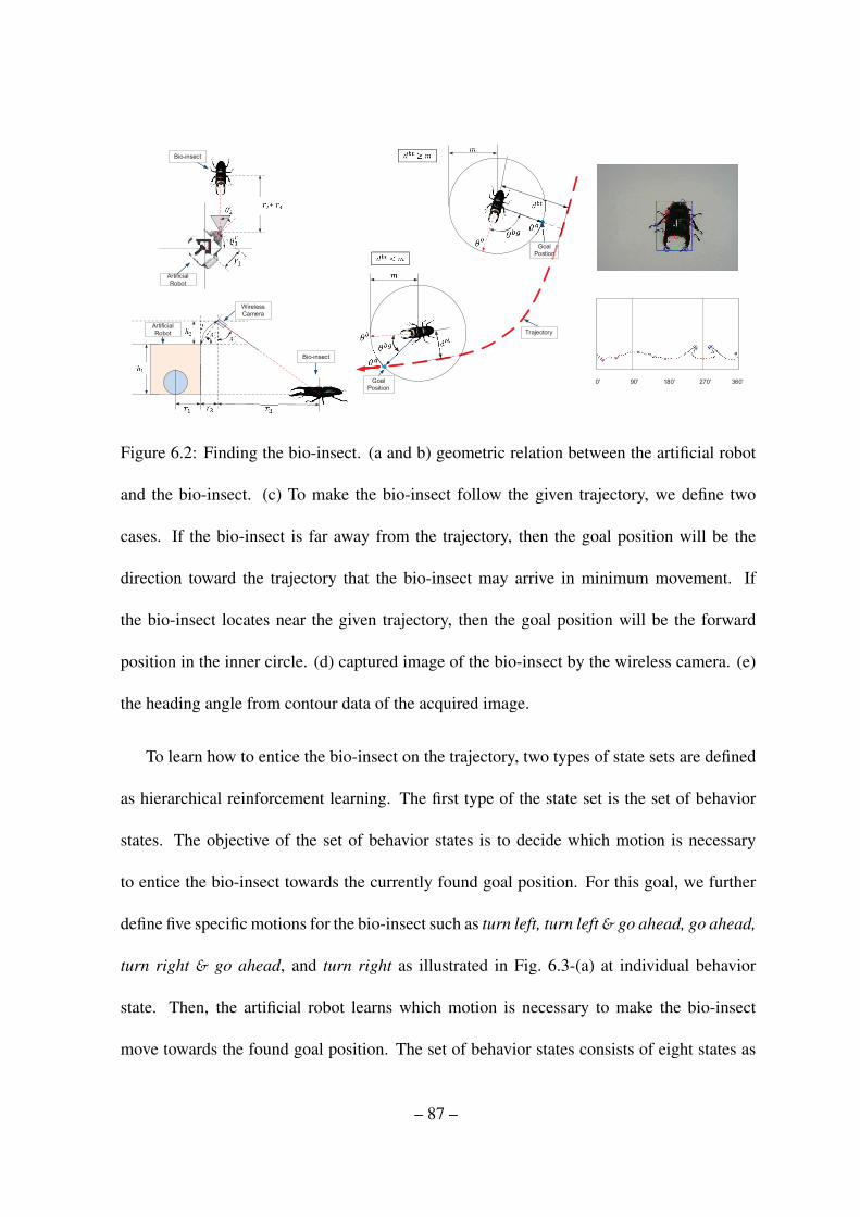
Figure 6.2: Finding the bio-insect. (a and b) geometric relation between the artificial robot
and the bio-insect. (c) To make the bio-insect follow the given trajectory, we define two
cases. If the bio-insect is far away from the trajectory, then the goal position will be the
direction toward the trajectory that the bio-insect may arrive in minimum movement. If
the bio-insect locates near the given trajectory, then the goal position will be the forward
position in the inner circle. (d) captured image of the bio-insect by the wireless camera. (e)
the heading angle from contour data of the acquired image.
To learn how to entice the bio-insect on the trajectory, two types of state sets are defined
as hierarchical reinforcement learning. The first type of the state set is the set of behavior
states. The objective of the set of behavior states is to decide which motion is necessary
to entice the bio-insect towards the currently found goal position. For this goal, we further
define five specific motions for the bio-insect such as turn left, turn left& go ahead, go ahead,
turn right & go ahead, and turn right as illustrated in Fig. 6.3-(a) at individual behavior
state. Then, the artificial robot learns which motion is necessary to make the bio-insect
move towards the found goal position. The set of behavior states consists of eight states as
– 87 –

illustrated in Fig. 6.3-(c). There are seven angular sections between the heading angle of
the bio-insect and goal direction; but at the central angular section, we further consider two
cases according to the distance ranges between goal and the bio-insect.
At recognized individual state, the bio-insect is driven such that it acts like one of the five
specific motions. If the distance between the bio-insect and the goal position dbg is less than
specific value and the heading angle of the bio-insect θbg is within the goal direction section,
then the state updates as 1 and becomes the goal of the behavior state. Then, the artificial
robot updates the behavior states by Q-learning under trial-and-error repetitively.
The second type of the states is a group of action states. The objective of the group of
action states is to make the bio-insect act as the chosen specific motion on the behavior state.
The group of action states contains five action states, and each action state is related with
each specific motion as follow: action state 1 - turn left, action state 2 - turn left & go ahead,
action state 3 - go ahead, action state 4 - turn right& go ahead, and action state 5 - turn right.
The set of action states is a combination of seven angular sections between heading angle of
the bio-insect and artificial robot direction, and three distance ranges between the bio-insect
and the artificial robot as illustrated in Fig. 6.3-(d). The action positions are located in the
center of each cell of the action state. If a specific motion has been chosen on a behavior state,
then the artificial robot finds a suitable action position to spread odor source near the bio-
insect as illustrated in Fig. 6.3-(b). To find a suitable action position, artificial robot explores
the chosen action states under own inner process. In the inner process, the artificial robot
virtually selects nine sub-actions, which consist of eight directions to move (up, down, left,
right, up-left, up-right, down-left, and down-right) and a choice of action position. Within
– 88 –

the limited sub-iteration steps in the inner process, the artificial robot explores to select an
action position and updates the action states by Q-learning. If the artificial robot has selected
an action position through the inner process, then it moves to the selected action position
and spreads the specific odor source to the bio-insect. During the actuation, if the bio-insect
moves into the shaded area of the selected motion as illustrated in the Fig. 6.3-(a), then the
selected action position on the related action state updates as 1, and the position becomes a
goal of the related action state. If the moving distance of the bio-insect or duration of the
actuation time exceeds each predefined value, then the artificial robot stops spreading odor
source at the iteration and tries to entice the bio-insect again. In the each action state, several
goals may exist. Therefore, additionally, the artificial robot counts the number of actions
and the number of achieved cases at every action state. Using the values, the artificial robot
calculates success rate of each goal position. If the artificial robot finds several goals in the
inner process, then it selects the goal, which has the highest successive rate.
6.4 Results
In the experiment, the learning rate for behavior states and action states is 0.9, the dis-
count factor for behavior states and action states is 0.85. The initial positions of the bio-
insect and artificial robot are not decided. To get more interaction opportunities between the
artificial robot and the bio-insect, the experiment always starts at near the center of the ex-
perimental platform. Every beginning of the experiment, we use the bio-insect that showed,
from the previous experiments, good reactivity among 12 numbers of Dorcus titanus castan-
icolor and 4 numbers of Dorcus hopei binodulosus. If reactivity of the bio-insect is getting
– 89 –
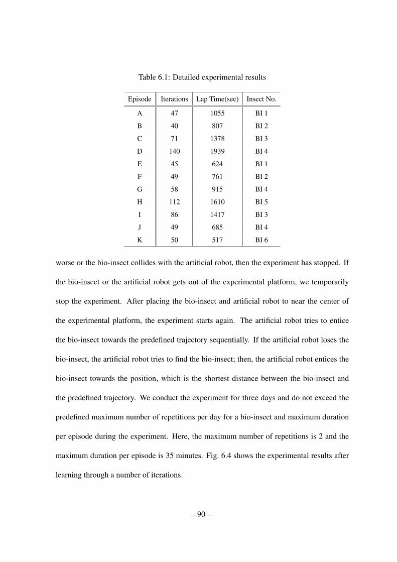
Table 6.1: Detailed experimental results
Episode Iterations Lap Time(sec) Insect No.
A 47 1055 BI 1
B 40 807 BI 2
C 71 1378 BI 3
D 140 1939 BI 4
E 45 624 BI 1
F 49 761 BI 2
G 58 915 BI 4
H 112 1610 BI 5
I 86 1417 BI 3
J 49 685 BI 4
K 50 517 BI 6
worse or the bio-insect collides with the artificial robot, then the experiment has stopped. If
the bio-insect or the artificial robot gets out of the experimental platform, we temporarily
stop the experiment. After placing the bio-insect and artificial robot to near the center of
the experimental platform, the experiment starts again. The artificial robot tries to entice
the bio-insect towards the predefined trajectory sequentially. If the artificial robot loses the
bio-insect, the artificial robot tries to find the bio-insect; then, the artificial robot entices the
bio-insect towards the position, which is the shortest distance between the bio-insect and
the predefined trajectory. We conduct the experiment for three days and do not exceed the
predefined maximum number of repetitions per day for a bio-insect and maximum duration
per episode during the experiment. Here, the maximum number of repetitions is 2 and the
maximum duration per episode is 35 minutes. Fig. 6.4 shows the experimental results after
learning through a number of iterations.
– 90 –

The experiments have been performed 747 iterations for 11708 sec.1. At the beginning
as shown in Fig. 6.4-(a), (b), (c), and (d) the moving path of the bio-insect does not follow
the predefined trajectory. After increasing the number of iterations, the moving paths of
the bio-insect are becoming similar to the shape of the given trajectory. Then, as shown in
Fig. 6.4-(k), we have eventually gotten a similar moving path of the bio-insect compared
with the predefined trajectory. Fig. 6.5-(b) shows the captured image of the moving path of
bio-insect corresponding to Fig. 6.4-(k). The sum of the total rewards of each state can be
considered as amounts of knowledge. The values have increased as the iterations increase as
shown in Fig. 6.5-(a). Then the values have converged to specific optimal quantities stably.
6.5 Conclusion
During the experiments, the bio-insect has shown uncertain and complex behavior occa-
sionally. For instance, when the artificial robot entices the bio-insect, the bio-insect suddenly
changes its moving direction. Then, it did not respond to the odor source spread by the arti-
ficial robot. These behaviors made the experiment difficult to proceed. In addition, reactivity
of the bio-insects to the specific odor source varies every day. A specific bio-insect did not
respond to the spread odor source, even though the specific bio-insect showed good response
from the odor source during the previous experiments. Therefore, we had to check reactive-
ness of the bio-insect before the experiments. These complex and uncertain behaviors of the
bio-insect might be caused from some unknown effects during the experiments. Unfortu-
nately, there were no clues why the behavior happened. One hypothesis is that the bio-insect
1Reader can download all movie clips by visiting the web site : http://dcas.gist.ac.kr/bioinsect
– 91 –

mainly relies on their antenna when sensing. To measure the odor source in air, the bio-insect
might need a break to groom their antenna for keeping its olfactory sensibility as reported
in K. Boroczky (2013). Due to different condition of the antenna of the bio-insect, its re-
activity from the odor source may be different every time. Another hypothesis is that the
bio-insect might learn that the odor source was not valuable from the previous interactions.
It has been known that a species of insects has an organ called mushroom bodies in its brain
and the mushroom bodies are the main organ for learning and memory Y. Li (1997). Several
types of experiments using specific odor sources showed that a cockroach has an olfactory
learning system composed of short-term memory and long-term memory D. D. Lent (2004);
M. Sakura (2001); S. Decker (2007). A bee also has a learning structure for foraging food
using visual and olfactory learning process to distinguish odor, shape, and color of the forag-
ing target Giurfa (2007); M. Hammer (1995). A cricket and a fly also have a similar olfactory
and visual memory structure Heisenberg (2003); S. Scotto-Lomassese (2003). In addition,
several studies reported that beetles also have mushroom bodies in their brain M. C. Lars-
son (2004); S. M. Farris (2005). From the studies, we can also consider that the bio-insect
has olfactory and visual memory structures based on mushroom bodies, and its learning and
memory structure might generate the complex behaviors during the experiments. For exam-
ple, the bio-insect did not receive actual reward during the experiments. Only an attractive
odor source made the bio-insect follow the artificial robot. Therefore, the bio-insect might
have learned that the odor source was useless. In addition, the bio-insect responded to move-
ment of the artificial robot rarely. In that case, the bio-insect turned towards the artificial
robot, even if the artificial robot did not spread the odor source. In the previous chapter 4
– 92 –
to find interaction mechanism between the artificial robot and the bio-insect, the bio-insect
did not respond to any movement of artificial robots and light sources though visual stimuli
might slightly affect the behavior of the bio-insect. In spite of the complex and unpredictable
behaviors during the experiments mentioned in the above, the artificial robot has success-
fully learned how to entice the bio-insect and eventually has made the bio-insect follow the
predefined trajectory.
– 93 –

Figure 6.3: States. (a) - To entice the bio-insect, we define five specific motions of the bio-
insect as follows: go ahead, turn left and go, rotate right, turn left and go, and rotate left. In
this experiment, the artificial robot learns which motion is necessary to make the bio-insect
move towards the found goal position using the behavior state. (b) - To make the bio-insect
act as the chosen motion on the behavior state, the artificial robot finds a suitable action
position to spread odor source near the bio-insect. (c) the set of behavior states - There are
seven angular sections between the heading angle of the bio-insect and goal direction; but at
the central angular section, we further consider two cases according to the distance ranges
between goal and the bio-insect. (d) the set of action states - The set of action states is a
combination of seven angular sections between heading angle of the bio-insect and artificial
robot direction and three distance ranges between the bio-insect and the artificial robot.
– 94 –

0 20 40 60 80 100 120 140 160 180 200
0
10
20
30
40
50
60
70
80
90
100
110
120
130
140
150
0 20 40 60 80 100 120 140 160 180 200
0
10
20
30
40
50
60
70
80
90
100
110
120
130
140
150
0 20 40 60 80 100 120 140 160 180 200
0
10
20
30
40
50
60
70
80
90
100
110
120
130
140
150
0 20 40 60 80 100 120 140 160 180 200
0
10
20
30
40
50
60
70
80
90
100
110
120
130
140
150
0 20 40 60 80 100 120 140 160 180 200
0
10
20
30
40
50
60
70
80
90
100
110
120
130
140
150
0 20 40 60 80 100 120 140 160 180 200
0
10
20
30
40
50
60
70
80
90
100
110
120
130
140
150
0 20 40 60 80 100 120 140 160 180 200
0
10
20
30
40
50
60
70
80
90
100
110
120
130
140
150
0 20 40 60 80 100 120 140 160 180 200
0
10
20
30
40
50
60
70
80
90
100
110
120
130
140
150
0 20 40 60 80 100 120 140 160 180 200
0
10
20
30
40
50
60
70
80
90
100
110
120
130
140
150
0 20 40 60 80 100 120 140 160 180 200
0
10
20
30
40
50
60
70
80
90
100
110
120
130
140
150
0 20 40 60 80 100 120 140 160 180 200
0
10
20
30
40
50
60
70
80
90
100
110
120
130
140
150
(a) - 0~47 Iterations (b) - 48~88 Iterations (c) - 89~158 Iterations
(d) - 159~298 Iterations (e) - 299~343 Iterations (f ) - 344~392 Iterations
(g) - 393~450 Iterations (h) - 451~563 Iterations (i)- 564~648 Iterations
(j) - 649~697 Iterations (k) - 698~747 Iterations
Trajectory
Bio-insect
X Axis (cm)
Y A
xis
(cm
)
X Axis (cm)
X Axis (cm)
Y A
xis
(cm
)Y
Axi
s (c
m)
Y A
xis
(cm
)
Figure 6.4: Experimental results - transition of the moving path of the bio-insect (blue dots)
as iterations increase.
– 95 –
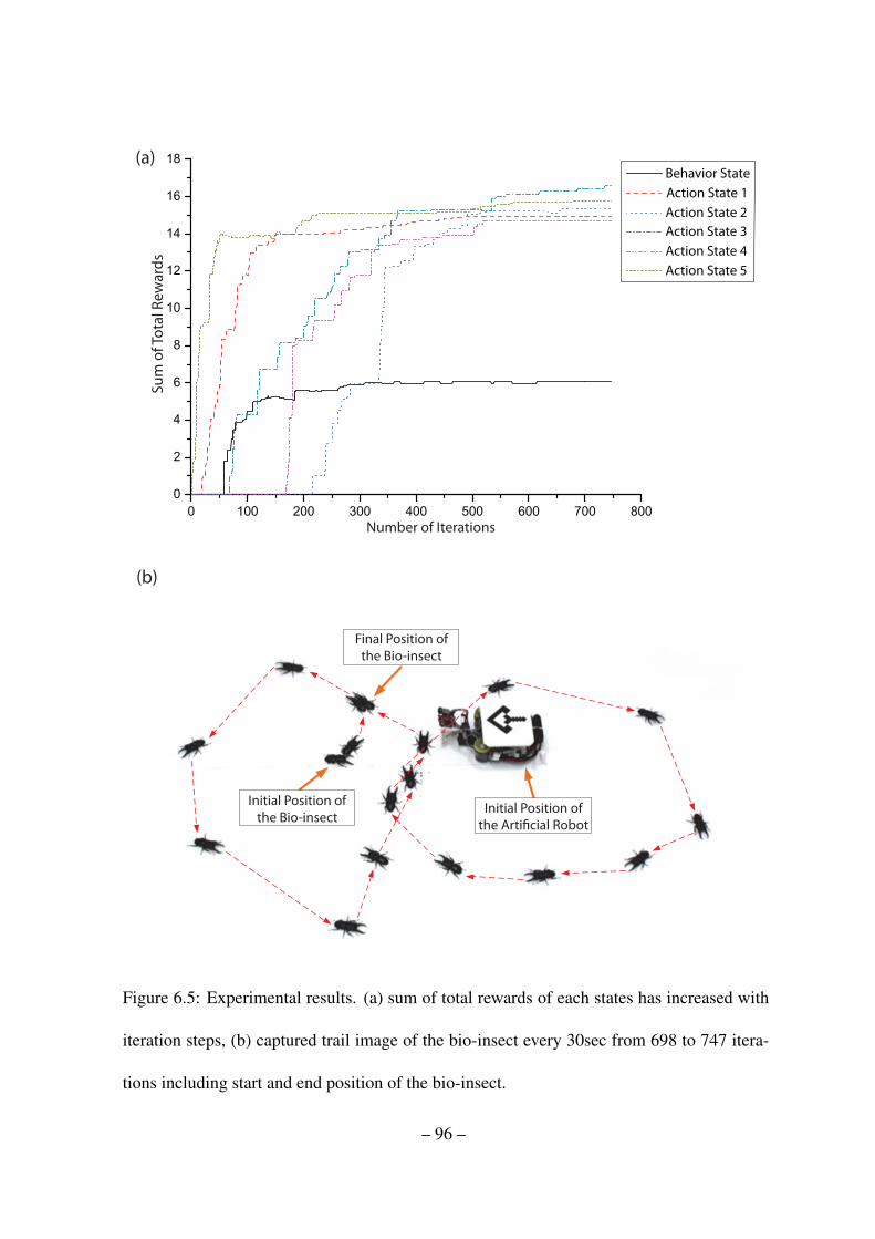
Su
m o
f T
ota
l R
ew
ard
s(a)
Behavior State
Action State 1
Action State 2
Action State 3
Action State 4
Action State 5
(b)
Number of Iterations
Final Position of
the Bio-insect
Initial Position of
the Bio-insect Initial Position of
the Arti!cial Robot
Figure 6.5: Experimental results. (a) sum of total rewards of each states has increased with
iteration steps, (b) captured trail image of the bio-insect every 30sec from 698 to 747 itera-
tions including start and end position of the bio-insect.
– 96 –
Chapter 7
Conclusion
In this thesis, we have presented interaction mechanism between bio-insect and artificial
robot, fuzzy-logic-based reinforcement learning, fuzzy-logic-based cooperative reinforce-
ment learning and hierarchical reinforcement learning to entice the bio-insect towards a de-
sired point or a predefined trajectory.
In Chapter 3, using the proposed interaction mechanism we discovered, the bio-insect
exhibits good reactivity from an odor source. However, the experimental results could not
reach a reliable success rate due to uncertain reactions of the bio-insect.
In Chapter 4, to entice the bio-insect in the real experiments, we have used a fuzzy-logic-
based reinforcement learning architecture to cope with the uncertain reaction conditions. In
this architecture, we have adopted fuzzy logic to generate a reward signal for an artificial
robot. It is not an easy task to generate a reward signal from the reaction of a bio-insect
under the selected actuation of the artificial robot. Applying fuzzy logic to distinguish the
reactions of the bio-insect helps generate a valuable reward signal for the artificial robot. In
this way, the reinforcement learning component learns what the artificial robot agent should
do to entice the bio-insect towards the given goal point by supplying a reward signal. Based
on the architecture, the robot agent can acquire knowledge of regarding how to entice the
bio-insect.
In Chapter 5, for multiple interactions between bio-insects and artificial robots, we have
– 97 –
presented a cooperative reinforcement learning technique using a fuzzy logic-based exper-
tise measurement system. Based on fuzzy-logic-based reinforcement learning, we have de-
signed a fuzzy-logic-based expertise measurement system to enhance the learning ability.
This structure enables the artificial robots to share knowledge while evaluating and measur-
ing the performance of each robot.
In Chapter 6, to conduct the experiment in realistic environment, the artificial robot only
uses a camera, which is attached on the body of the robot, for detecting and finding the po-
sition and heading angle of the bio-insect. Thus, the robot only relies on locally-obtained
knowledge for enticing the bio-insect. To deal with the limitation, we have presented hierar-
chical reinforcement learning for interaction between the bio-insect and the artificial robot.
Using the hierarchical reinforcement learning, the artificial robot has learned how to entice
the bio-insect into following closely along the given trajectory using hierarchical reinforce-
ment learning. Based on the learning architecture, the artificial robot has attempted to learn
the reactions of the bio-insect.
In the experiments, we do not consider repeatability of the experiments. To conduct the
experiments, we have to check status and physical strength of the bio-insect every time and
the learning algorithms still need a huge amount of time to achieve the goals. Thus, it is
difficult to conduct numerous experiments to show repeatability of the algorithms. At least,
we may argue that the experiments will show similar experimental results if we conduct the
experiments again. Because we mainly use reinforcement learning and it is well known that
the reinforcement learning converges to an optimal policy. Therefore, if the bio-insect shows
good reactivity from the actuation method we have found, then the artificial robot fully learns
– 98 –

how to entice the bio-insect and achieves the goals to entice the bio-insect towards predefined
goal area or trajectory. In spite of the complex and unpredictable behaviors of the bio-insect
during the experiments mentioned in the above, the artificial robot has successfully learned
how to entice the bio-insect and eventually has made the bio-insect follow the predefined goal
or trajectory. From the experimental results, we can reach the conclusion that an artificial
robot could learn, without any human aid, how to interact with a living bio-insect for a
specific simple task in ideal circumstances.
We believe that these results will provide clues in developing a dominant architecture for
robot intelligence. In these experiments, we have only considered the interaction between
an artificial robot(s) and a bio-insect based on several robot intelligence structures as a basic
step. There are still some problems to be addressed: learning still consumes a huge amount
of time, and the learning structures still can not fully handle the uncertain and complex
behavior of the bio-insect. We will discuss these problems in future research.
– 99 –
References
A. Bozkurt, et al (2009). Insect-machine interface based neurocybernetics.. IEEE Transac-
tions on Biomedical Engineering 56(6), 1727–1733.
Abbeel, Pieter, Coates, Adam, Quigley, Morgan, & Ng, Andrew Y (2007). An application
of reinforcement learning to aerobatic helicopter flight. Advances in neural information
processing systems 19, 1.
Abdulhai, Baher, Pringle, Rob, & Karakoulas, Grigoris J (2003). Reinforcement learning for
true adaptive traffic signal control. Journal of Transportation Engineering 129(3), 278–
285.
Ahmadabadi, MN, & Asadpour, M. (2002). Expertness based cooperative Q-learning. IEEE
Trans. Syst. Man Cybern. B, Cybern. 32(1), 66–76.
Ahmadabadi, MN, Imanipour, A., Araabi, BN, Asadpour, M., & Siegwart, R. (2006).
Knowledge-based Extraction of Area of Expertise for Cooperation in Learning. In the
Proceedings of 2006 IEEE/RSJ Int. Conf. on Intelligent Robots and Systems. pp. 3700–
3705.
Araabi, B.N., Mastoureshgh, S., & Ahmadabadi, M.N. (2007). A Study on Expertise of
Agents and Its Effects on Cooperative Q-Learning. IEEE Trans. Syst. Man Cybern. B,
Cybern. 37(2), 398–409.
Barto, A, & Crites, RH (1996). Improving elevator performance using reinforcement learn-
ing. Advances in neural information processing systems 8, 1017–1023.
– 100 –
Bohlen, M. (1999). A robot in a cage. In International Symposium on Computational Intel-
ligence in Robotics and Automation pp. 214–219.
Boyan, Justin A, & Littman, Michael L (1994). Packet routing in dynamically changing
networks: A reinforcement learning approach. Advances in neural information processing
systems pp. 671–671.
Courses, E., & Surveys, T. (2008). A Comprehensive Survey of Multiagent Reinforcement
Learning. IEEE Trans. Syst. Man Cybern. C, Appl. Rev. 38(2), 156–172.
D. D. Lent, H. W. Kwon (2004). Antennal movements reveal associative learning in the
american cockroach periplaneta americana. Journal of experimental biology 207(2), 369–
375.
Duan, Yong, Liu, Qiang, & Xu, XinHe (2007). Application of reinforcement learning in
robot soccer. Engineering Applications of Artificial Intelligence 20(7), 936–950.
Erus, G., & Polat, F. (2007). A layered approach to learning coordination knowledge in
multiagent environments. Applied Intelligence 27(3), 249–267.
Gambardella, Luca Maria, Dorigo, Marco et al. (1995). Ant-q: A reinforcement learning
approach to the traveling salesman problem. pp. 252–260.
Giurfa, M. (2007). Behavioral and neural analysis of associative learning in the honeybee: a
taste from the magic well. Journal of Comparative Physiology A 193(8), 801–824.
H. Sato, et al. (2008). A cyborg beetle: insect flight control through an implantable, tetherless
– 101 –

microsystem. IEEE 21st International Conference on Micro Electro Mechanical Systems
pp. 164–167.
H. Sato, et al. (2009). Radio-controlled cyborg beetles: a radio-frequency system for insect
neural flight control. IEEE 22nd International Conference on Micro Electro Mechanical
Systems pp. 216–219.
Heisenberg, M. (2003). Mushroom body memoir: from maps to models. Nature Reviews
Neuroscience 4(4), 266–275.
Hopgood, A.A. (2003). Artificial intelligence: hype or reality?. IEEE Computer Magazine
36(5), 24–28.
J. Halloy, et al. (2007). Social integration of robots into groups of cockroaches to control
self-organized choices. Science 318(5853), 1155–1158.
Ji-Hwan Son, Young-Cheol Choi, Hyo-Sung Ahn (2014). Bio-insect and artificial robot in-
teraction using cooperative reinforcement learning. Applied Soft Computing 25, 322–335.
K. Boroczky, et al. (2013). Insects groom their antennae to enhance olfactory acuity. Pro-
ceedings of the National Academy of Sciences 110(9), 3615–3620.
K. Kawabata, H. Aonuma, K. Hosoda J. Xue (2013). Active interaction utilizing micro
mobile robot and on-line data gathering for experiments in cricket pheromone behavior.
Robotics and Autonomous Systems 61(12), 1529–1538.
Kaelbling, L. P., Littman, M. L., & Moore, A. W. (1996). Reinforcement Learning: A Sur-
vey. J. Artif. Intell. Res. 4, 237–285.
– 102 –
Kok, J.R., & Vlassis, N. (2006). Collaborative Multiagent Reinforcement Learning by Payoff
Propagation. The Journal of Machine Learning Research 7, 1789–1828.
Lanzi, Pier Luca (2002). Learning classifier systems from a reinforcement learning perspec-
tive. Soft Computing-A Fusion of Foundations, Methodologies and Applications 6(3), 162–
170.
Leng, Jinsong, & Lim, Chee Peng (2011). Reinforcement learning of competitive and coop-
erative skills in soccer agents. Applied soft computing 11(1), 1353–1362.
Littman, M.L. (1994). Markov games as a framework for multi-agent reinforcement learning.
Proc. of the Eleventh Int. Conf. on Machine Learning.
M. C. Larsson, B. S. Hansson, N. J. Strausfeld (2004). A simple mushroom body in an
african scarabid beetle. Journal of Comparative Neurology 478(3), 219–232.
M. Hammer, R. Menzel (1995). Learning and memory in the honeybee. The Journal of Neu-
roscience 15(3), 1617–1630.
M. Sakura, M. Mizunami (2001). Olfactory learning and memory in the cockroach periplan-
eta americana. Zoological Science 18(1), 21–28.
Merrick, Kathryn Elizabeth (2010). A comparative study of value systems for self-motivated
exploration and learning by robots. IEEE Transactions on Autonomous Mental Develop-
ment 2(2), 119–131.
Nikravesh, Masoud (2008). Evolution of fuzzy logic: from intelligent systems and computa-
tion to human mind. Soft Computing 12(2), 207–214.
– 103 –
Nunes, L., & Oliveira, E. (2003). Advice-Exchange Amongst Heterogeneous Learning
Agents: Experiments in the Pursuit Domain. poster abstract) Autonomous Agents and
Multiagent Systems (AAMAS03).
Panait, L., & Luke, S. (2005). Cooperative Multi-Agent Learning: The State of the Art.
Autonomous Agents and Multi-Agent Systems 11(3), 387–434.
Peters, Jan, Vijayakumar, Sethu, & Schaal, Stefan (2003). Reinforcement learning for hu-
manoid robotics. pp. 1–20.
Purnamadjaja, A. H., & Russell, R. A. (2007). Guiding robots behaviors using pheromone
communication. Autonomous Robots 23(2), 113–130.
Q. Shi, et al. (2013). Modulation of rat behaviour by using a rat-like robot. Bioinspiration &
biomimetics.
R. Holzer, I., Shimoyama (1997). Locomotion control of a bio-robotic system via electric
stimulation. Proceedings of the /RSJ International Conference on Intelligent Robots and
Systems 3, 1514–1519.
R. Vaughan, et al. (2000). Experiments in automatic flock control. Robotics and Autonomous
Systems 31(1), 109–117.
Ritthipravat, P., Maneewarn, T., Wyatt, J., & Laowattana, D. (2006). Comparison and Anal-
ysis of Expertness Measure in Knowledge Sharing Among Robots. Lecture Notes in Com-
puter Science 4031, 60.
– 104 –
S. Decker, S. McConnaughey, T. L. Page (2007). Circadian regulation of insect olfactory
learning. Proceedings of the National Academy of Sciences 104(40), 15905–15910.
S. Lee, et al. (2013). Remote guidance of untrained turtles by controlling voluntary instinct
behavior.. PloS one.
S. M. Farris, N. S. Roberts (2005). Coevolution of generalist feeding ecologies and gyren-
cephalic mushroom bodies in insects. Proceedings of the National Academy of Sciences
of the United States of America 102(48), 17394–17399.
S. Marras, M. Porfiri (2012). Fish and robots swimming together: attraction towards
the robot demands biomimetic locomotion. Journal of the Royal Society Interface
9(73), 1856–1868.
S. Scotto-Lomassese, et al. (2003). Suppression of adult neurogenesis impairs olfactory
learning and memory in an adult insect. The Journal of neuroscience 23(28), 9289–9296.
Salmeron, Jose L (2012). Fuzzy cognitive maps for artificial emotions forecasting. Applied
Soft Computing 12(12), 3704–3710.
Sharma, Rajneesh, & Gopal, Madan (2010). Synergizing reinforcement learning and game
theory - a new direction for control. Applied Soft Computing 10(3), 675–688.
Son, J.-H., & Ahn, H.-S. (Oct. 2008). Cooperative Reinforcement Learning: Brief Sur-
vey and Application to Bio-insect and Artificial Robot Interaction. In the Proceedings of
IEEE/ASME Int. Conf. on Mechtronic and Embedded Syst. and Applicat.. Beijing, China.
pp. 71–76.
– 105 –

Son, Ji-Hwan, & Ahn, Hyo-Sung (2014). Bio-insect and artificial robot interaction: Learning
mechanism and experiment. Soft Computing 18(6), 1127–1141.
Sugeno, M., & Yasukawa, T. (1993). A fuzzy-logic-based approach to qualitative modeling.
IEEE Trans. Fuzzy Syst. 1(1), 7–31.
Sutton, R. S., & Barto, A. G. (1998). Reinforcement Learning: An Introduction. MIT Press.
Tan, M (1993). Multi-agent reinforcement learning : Independent vs. cooperative agents.
In the Proceedings of in ‘Proc., Tenth Int. Conf. on Machine Learning’. Vol. 1. Amherst.
pp. 330–337.
Tangamchit, P., Dolan, J.M., & Khosla, P.K. (2002). The necessity of average rewards in
cooperative multirobot learning. In the Proceedings of IEEE Int. Conf. on Robotics and
Automation, 2002. Vol. 2. IEEE. pp. 1296–1301.
Tesauro, Gerald, Jong, Nicholas K, Das, Rajarshi, & Bennani, Mohamed N (2006). A hybrid
reinforcement learning approach to autonomic resource allocation. pp. 65–73.
W. M. Tsang, et al. (2010). Remote control of a cyborg moth using carbon nanotube-
enhanced flexible neuroprosthetic probe.. IEEE 23rd International Conference on Micro
Electro Mechanical Systems pp. 39–42.
Walker, Marilyn A (2000). An application of reinforcement learning to dialogue strategy
selection in a spoken dialogue system. Journal of Artificial Intelligence Research 12, 387–
416.
– 106 –

Wang, Y., & de Silva, CW (2006). Multi-robot Box-pushing: Single-Agent Q-Learning vs.
Team Q-Learning. Intelligent Robots and Systems, 2006 IEEE/RSJ Int. Conf. on pp. 3694–
3699.
Wang, Y., & de Silva, C.W. (2008). A machine-learning approach to multi-robot coordina-
tion. Engineering Applications of Artificial Intelligence 21(3), 470–484.
Wang, Yi-Chi, & Usher, John M (2005). Application of reinforcement learning for
agent-based production scheduling. Engineering Applications of Artificial Intelligence
18(1), 73–82.
Y. Kuwana, S. Nagasawa, I. Shimoyama R. Kanzaki (1999). Synthesis of the pheromone-
oriented behaviour of silkworm moths by a mobile robot with moth antennae as
pheromone sensors. Biosensors and Bioelectronics 14(2), 195–202.
Y. Li, N. J. Strausfeld (1997). Morphology and sensory modality of mushroom body extrinsic
neurons in the brain of the cockroach, periplaneta americana. Journal of Comparative
Neurology 387(4), 631–650.
Zadeh, L. A. (1975). The concept of a linguistic variable and its application to approximate
reasoning-I. Inform. Sci. 8(3), 199–249.
– 107 –

감사의글
짧지 않은 대학원 생활을 마무리 하며 지난 시간을 뒤돌아 보니 아쉬움과 후회가 남
습니다. 학업적 성취에 있어서의 아쉬움만이 아닌, 고마운 분들께 감사의 마음을 제
대로 전달하지 못해 더욱 그러한 것 같습니다. 그 동안 저에게 많은 격려와 힘을 주
시고 올바른 방향으로 이끌어 주신 많은 분들께 감사의 마음을 전하고자 합니다. 먼
저,학위과정동안독립된연구자가될수있도록지도를해주신안효성교수님께진
심으로 감사 드립니다. 아낌없는 지도와 가르침 속에 대학원 생활을 무사히 마칠 수
있었습니다. 또한몸소보여주셨던연구자로서의열정은귀중한가르침이되었습니
다. 논문심사과정에서도아낌없는지도로많은가르침을주신기전공학부고광희교
수님, 이종호 교수님, 정보통신공학부 전문구 교수님, 전성찬 교수님께도 감사 드립
니다. 석사및박사기간동안항상저를믿고도와준분산제어및자동화시스템연구
실의환이형,광교형,병연이,영철이형,상철이형,승주,영훈,명철,병훈,성모,귀한,
재경,석영,국환,영훈, Minh Hoang Trinh,유빈, Yan Geng에게도고맙다는말을전하
고자합니다. 학위과정을진행하면서인연이되었던태경이형,한얼,상혁이형,윤태,
재영, 그리고 타지에서도 계속 소식을 주고받으면서 격려해 준 Tong Duy Son, Stefan
Dukov에게도감사의말을전합니다. 특히,환이형과광교형은연구실의든든한조언
자이자인생의선배로서많이배우고의지할수있었습니다. 병연이는석사과정부터
동기로서쉽지않았던학위기간동안든든한동반자역할을해주었습니다. 언제나든
든한조언자역할을해주시는아버지와항상저를따듯하게품어주시는어머니,가족
에게많은신경을쓰지못하는저를대신해서항상가족을챙겨준동생지영 (그래,딸
이최고다!),그리고우리가족의막둥이애교담당토리에게도감사의말을전합니다.
또한이곳에언급하지못했지만지금까지제가성장해올수있도록도움을주신많은
– 108 –

분들께도감사의말을전합니다. 박사과정의졸업이하나의막을내리고연구자로서
서막을올리는중요한시점이라고생각합니다. 이시점에서독립된연구자로서계속
성장해나가겠다는다짐을하며글을맺고자합니다.
– 109 –

Curriculum vitae
• Name: Ji-Hwan Son
• Birth date: Jun. 4, 1983
• Birth place: Gwangmyeong-si, Gyeonggi-do, South Korea
• Address: Gwangju, South Korea
Education
• Ph.D., School of Mechatronics, Gwangju Institute of Science and Technology, Gwangju,
South Korea, Feb. 2015.
• M.S., Information and Mechatronics, Gwangju Institute of Science and Technology,
Gwangju, South Korea, Feb. 2010.
• B.S., Electronics Engineering, Sejong University, Seoul, South Korea, Feb. 2008.
Professional Activities
IEEE student member, 2008-Present
– 110 –

Publications
Journal papers
1. Ji-Hwan Son, Young-Cheol Choi and Hyo-Sung Ahn, “Bio-insect and Artificial RobotInteraction using Cooperative Reinforcement Learning,” Applied Soft Computing, Vol-ume 25, Pages 322-335, Dec. 2014.
2. Ji-Hwan Son and Hyo-Sung Ahn, “Formation Coordination for Self-mobile Localiza-tion: Algorithms and Experiment,” IEEE Systems Journal, 2014.
3. Ji-Hwan Son and Hyo-Sung Ahn, “Bio-insect and Artificial Robot Interaction: Learn-ing Mechanism and Experiment,” Soft Computing, Volume 18, Issue 6, Pages 1127-1141, Jun. 2014.
4. Hyo-Sung Ahn, Okchul Jung, Sujin Choi, Ji-Hwan Son, Daewon Chung, and GyusunKim, “An optimal satellite antenna profile using reinforcement learning,” IEEE Trans-actions on System, Man and Cybernetics Part-C, Volume 41, Issue 3, Pages 393-406,May 2011.
5. Ji-Hwan Son and Hyo-Sung Ahn, “A Robot Learns How to Entice a Bio-insect,” (1strevision).
Conference papers
1. Ji-Hwan Son and Hyo-Sung Ahn, “Bio-insect and Artificial Robot Interaction usingCooperative Reinforcement Learning,” Proceedings of the 2012 IEEE Multi-Conferenceon Systems and Control (MSC), Dubrovnik, Croatia, 2012.
2. Ji-Hwan Son and Hyo-Sung Ahn, “Fuzzy reward based cooperative reinforcementlearning for bio-insect and artificial robot interaction,” Proceedings of the 2009 IEEE/ASMEInt. Conf. Mechatronics and Embedded Systems and Applications, San diego, Califor-nia, USA, 2009.
3. Ji-Hwan Son and Hyo-Sung Ahn, “Bio-insect and Artificial Robots Interaction: ADragging Mechanism and Experimental Results,” Proceedings of the 2009 IEEE In-ternational Symposium on Computational Intelligence in Robotics and Automation,Daejeon, Korea, 2009.
4. Ji-Hwan Son and Hyo-Sung Ahn, “Cooperative reinforcement learning: Brief sur-vey and application to bio-insect and artificial robot interaction,” Proceedings of the2008 IEEE/ASME Int. Conf. Mechatronics and Embedded Systems and Applications,Beijing, China, 2008.
Domestic Conference papers
– 111 –

1. 손지환,안효성, “협동강화학습실험을위한바이오곤충과로봇의상호작용플랫폼설계”한국자동제어학술회의 (KACC 2009),부산, 2009.
2. 이남수,안효성,이재청,김병연,손지환, “Embedded system기반의퍼지제어기를통한이동로봇의장애물회피및주행제어기”제 3회한국지능로봇종합학술대회,창원, 2008.
– 112 –