Embed Size (px)
Citation preview
The deterioration of concrete
The
dete
rior
atio
n of
con
crete
C.P.
MK
6851
30 (G
B) 0
7/11
HEADQUARTERSMAPEI SpA Via Cafiero, 2220158 Milan - ItalyTel. +39 02 37673.1Fax +39 02 37673.214Internet: www.mapei.comE-mail: [email protected]
The deterioration of concrete
The
dete
rior
atio
n of
con
cret
e
C.P.
MK
6851
30 (G
B) 0
7/11
HEADQUARTERSMAPEI SpA Via Cafiero, 2220158 Milan - ItalyTel. +39 02 37673.1Fax +39 02 37673.214Internet: www.mapei.comE-mail: [email protected]
C.P
. MK
725
130
(GB
) 07/
11
Rep
airs
to b
ridg
es a
nd v
iadu
cts
Repairs to bridges and viaducts
HEADQUARTERSMAPEI SpA Via Cafiero, 2220158 Milan - ItalyTel. +39 02 37673.1Fax +39 02 37673.214Internet: www.mapei.comE-mail: [email protected]
C.P
. MK
661
530
(GB
) 06/
11
Prot
ecti
on a
nd R
epai
r of c
oncr
ete
in c
ompl
ianc
e w
ith
Euro
pean
Sta
ndar
d U
NI E
N 15
04
Protection and Repair of concretein compliance with European Standard UNI EN 1504
HEADQUARTERSMAPEI SpA Via Cafiero, 22 - 20158 MilanTel. +39-02-37673.1 Fax +39-02-37673.214Internet: www.mapei.comE-mail: [email protected]
C.P.
MK
7151
30 (G
B) 0
7/09
Rep
airs
to fa
çade
s
Repairs to façades
MAPEI SpA Via Cafiero, 22 - 20158 MilanTel. +39 02 37673.1Fax +39 02 37673.214Internet: www.mapei.comE-mail: [email protected]
C.P.
MK
6951
30 (G
B) 0
7/09
Rep
airs
to W
ater
Ret
aini
ng S
truc
ture
s
Repairs toWater Retaining Structures
MAPEI SpA Via Cafiero, 22 - 20158 MilanTel. +39 02 37673.1Fax +39 02 37673.214Internet: www.mapei.comE-mail: [email protected]
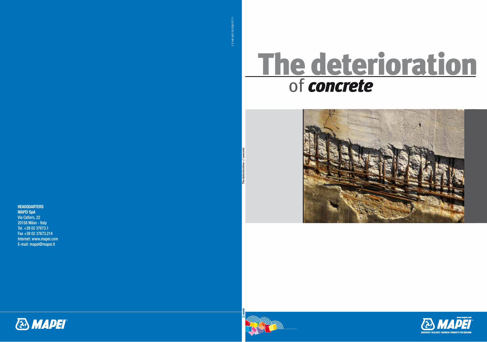
Mapei produces a series of technical manuals so that the subject of the deterioration of concrete may
be analysed in depth, and to offer a professional approach to the problems regarding repair work.
The subject of this manual is:
The deterioration of concrete
The manuals are available upon request.
The other manuals available in the series are:
C.P.
MK
7029
10 (I
) 01/
10
Il ri
pris
ino
delle
str
uttu
re fo
gnar
ie
The repair of sewage systems
SEDEMAPEI Spa Via Cafiero, 22 - 20158 MilanoTel. +39-02-37673.1 Fax +39-02-37673.214Internet: www.mapei.comE-mail: [email protected]
C.P.
MK
8388
10 (I
) 01/
10
La p
rote
zion
e ca
todi
ca g
alva
nica
Cathodic GalvanicProtection
SEDEMAPEI Spa Via Cafiero, 22 - 20158 MilanoTel. +39-02-37673.1 Fax +39-02-37673.214Internet: www.mapei.comE-mail: [email protected]
|1
The deterioration of concrete
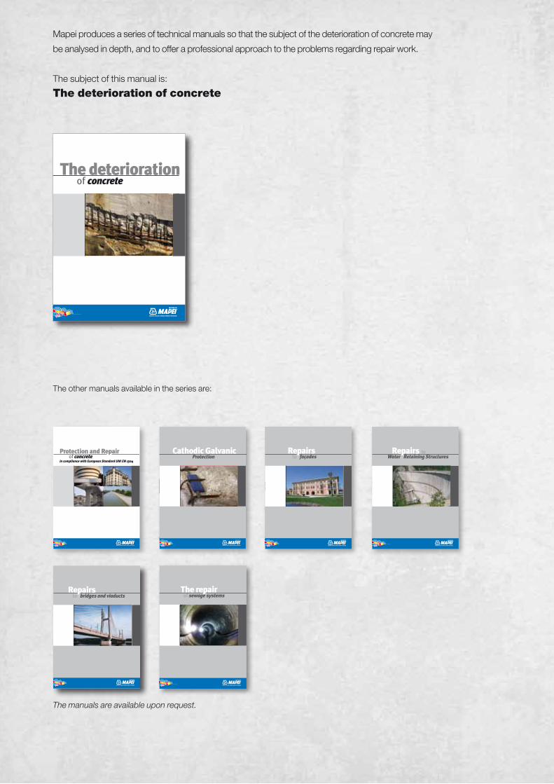
Index 1| Introduction 2
2| The deterioration of concrete 4
3| Aggression by chemicals 5
3.1| Aggression by carbon dioxide 5 3.1.1| Diagnosis of deterioration due to carbonatation 7 3.1.2| Diagnosis of deterioration due to leaching 8 3.2| Aggression by sulphates 9 3.2.1| Diagnosis of deterioration due to sulphate attack 10 3.3| Aggression by chlorides 11 3.3.1| Diagnosis of deterioration due to attack by chlorides 12 3.4| Alkali-aggregates reaction 13 3.4.1| Diagnosis of deterioration due to alkali-aggregates reaction 14
4| Aggression by physical elements 15 4.1| Freezing and thawing 15 4.2| High temperatures 17 4.3| Shrinkage and cracking 19
5| Aggression by mechanical elements 20 5.1| Abrasion 20 5.2| Impact 21 5.3| Erosion 22 5.4| Cavitation 22
6| Defects 22
7| Exposition classes 25
2|
1| Introduction
around 25 BC, the use of conglomerates, or “opus caementitium” in Latin, defined as a blend
of lime, sand and water mixed together with pieces of stone and bricks is discussed. These
examples clearly illustrate the antique origins of the material we will try to analyse. In order to
discuss “modern” concrete, we must go to the beginning of the 19th century. The binder used
in the mix derived from baking earth made up of clay and limestone, at temperatures of up to
1500°C, to form clinker pellets. When mixed with suitable grinding additives and then ground
up, it took the name of Portland cement, because of its resemblance to Portland stone.
Concrete used in the modern era is a mixture of water, cement, aggregates and, where
required, admixtures (plasticisers, super-plasticisers, etc.), added according to EN 934-
2:2002 Standards, which modify its rheology, properties and performance characteristics.
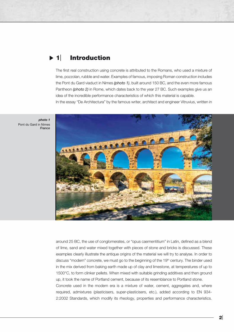
photo 1Pont du Gard in Nimes
France
The first real construction using concrete is attributed to the Romans, who used a mixture of
lime, pozzolan, rubble and water. Examples of famous, imposing Roman construction includes
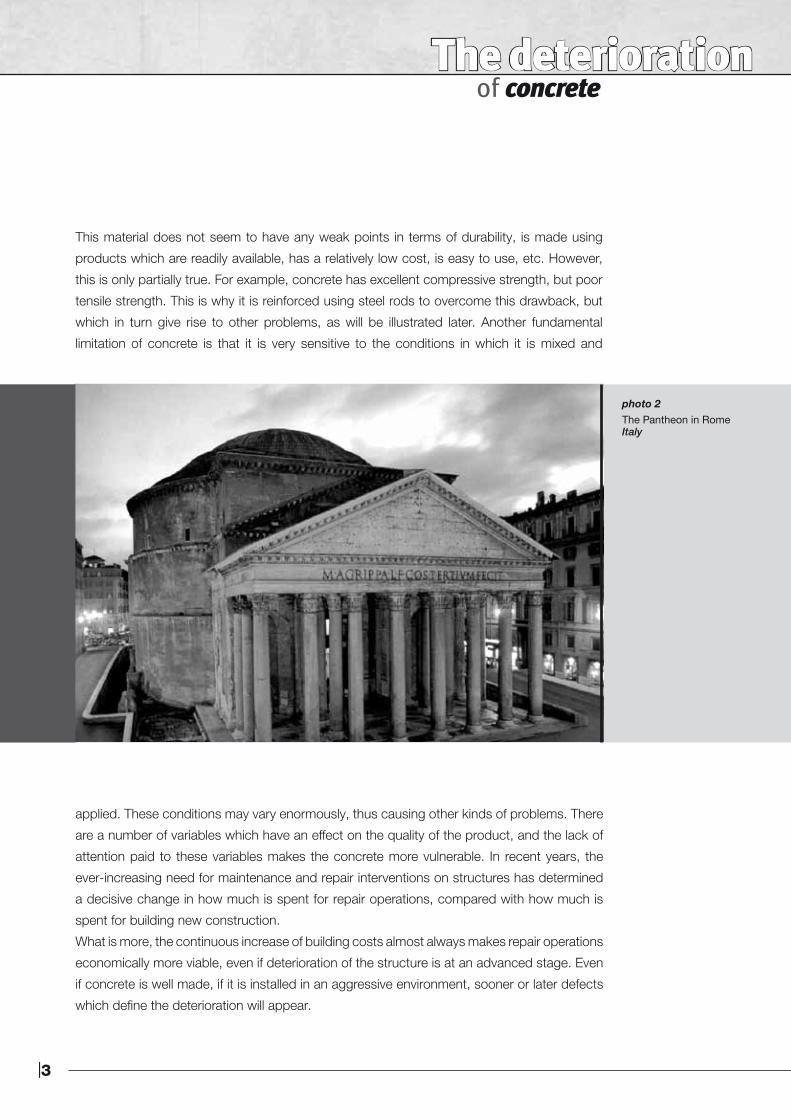
the Pont du Gard viaduct in Nimes (photo 1), built around 150 BC, and the even more famous
Pantheon (photo 2) in Rome, which dates back to the year 27 BC. Such examples give us an
idea of the incredible performance characteristics of which this material is capable.
In the essay “De Architectura” by the famous writer, architect and engineer Vitruvius, written in
|3
The deterioration of concrete
This material does not seem to have any weak points in terms of durability, is made using
products which are readily available, has a relatively low cost, is easy to use, etc. However,
this is only partially true. For example, concrete has excellent compressive strength, but poor
tensile strength. This is why it is reinforced using steel rods to overcome this drawback, but
which in turn give rise to other problems, as will be illustrated later. Another fundamental
limitation of concrete is that it is very sensitive to the conditions in which it is mixed and
applied. These conditions may vary enormously, thus causing other kinds of problems. There
are a number of variables which have an effect on the quality of the product, and the lack of
attention paid to these variables makes the concrete more vulnerable. In recent years, the
ever-increasing need for maintenance and repair interventions on structures has determined
a decisive change in how much is spent for repair operations, compared with how much is
spent for building new construction.
What is more, the continuous increase of building costs almost always makes repair operations
economically more viable, even if deterioration of the structure is at an advanced stage. Even
if concrete is well made, if it is installed in an aggressive environment, sooner or later defects
which define the deterioration will appear.
photo 2The Pantheon in RomeItaly
4|
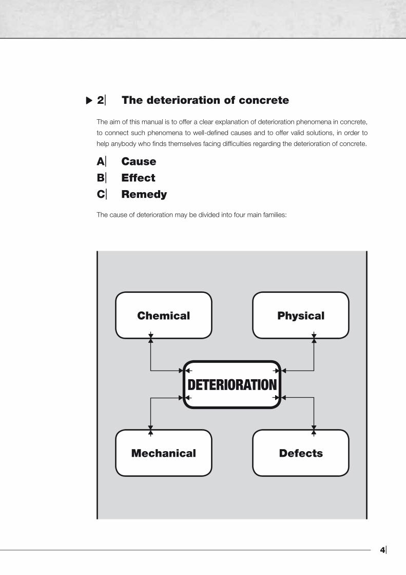
DETERIORATION
Chemical
Mechanical
Physical
Defects
2| The deterioration of concrete
The aim of this manual is to offer a clear explanation of deterioration phenomena in concrete,
to connect such phenomena to well-defined causes and to offer valid solutions, in order to
help anybody who finds themselves facing difficulties regarding the deterioration of concrete.
A| CauseB| EffectC| Remedy
The cause of deterioration may be divided into four main families:
|5
3.1| Aggression by carbon dioxide 3.2| Aggression by sulphates 3.3| Aggression by chlorides 3.4| Alkali-aggregates reaction
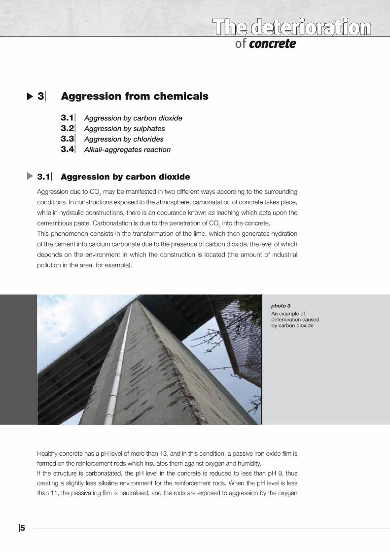
3.1| Aggression by carbon dioxide
Aggression due to CO2 may be manifested in two different ways according to the surrounding
conditions. In constructions exposed to the atmosphere, carbonatation of concrete takes place,
while in hydraulic constructions, there is an occurance known as leaching which acts upon the
cementitious paste. Carbonatation is due to the penetration of CO2 into the concrete.
This phenomenon consists in the transformation of the lime, which then generates hydration
of the cement into calcium carbonate due to the presence of carbon dioxide, the level of which
depends on the environment in which the construction is located (the amount of industrial
pollution in the area, for example).
Healthy concrete has a pH level of more than 13, and in this condition, a passive iron oxide film is formed on the reinforcement rods which insulates them against oxygen and humidity.If the structure is carbonatated, the pH level in the concrete is reduced to less than pH 9, thus creating a slightly less alkaline environment for the reinforcement rods. When the pH level is less than 11, the passivating film is neutralised, and the rods are exposed to aggression by the oxygen
The deterioration of concrete
photo 3An example ofdeterioration causedby carbon dioxide
3| Aggression from chemicals
6|
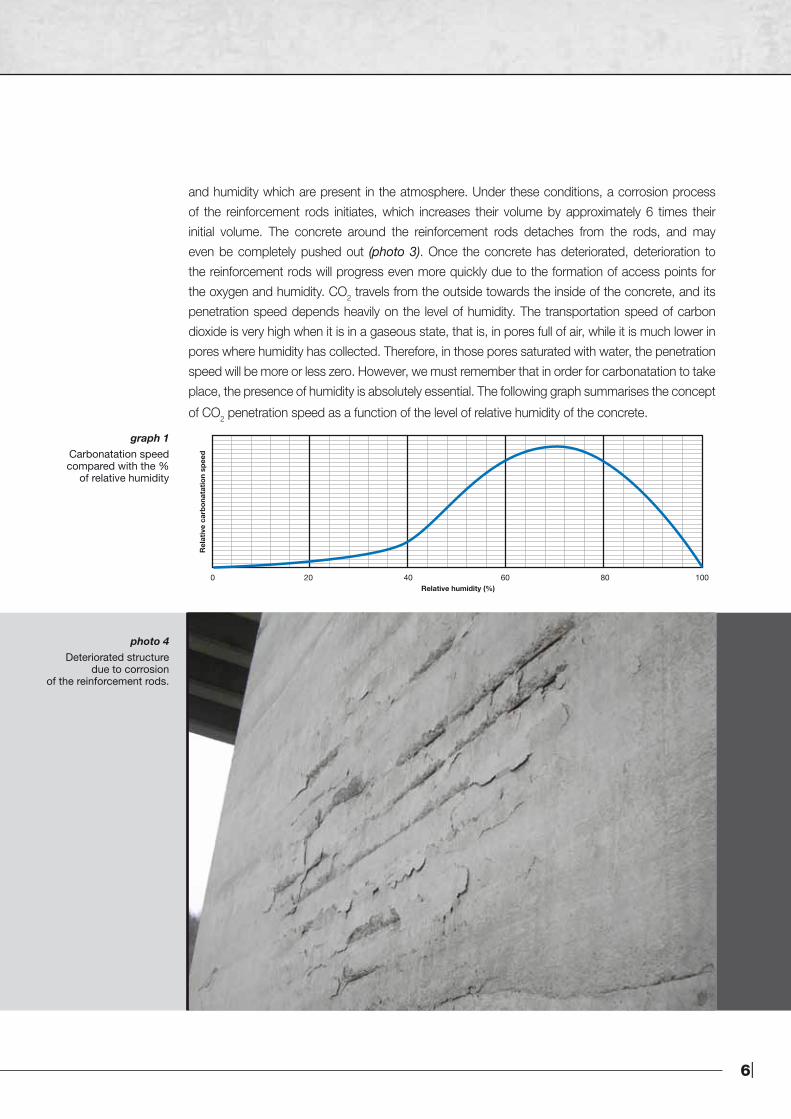
and humidity which are present in the atmosphere. Under these conditions, a corrosion process of the reinforcement rods initiates, which increases their volume by approximately 6 times their initial volume. The concrete around the reinforcement rods detaches from the rods, and may even be completely pushed out (photo 3). Once the concrete has deteriorated, deterioration to the reinforcement rods will progress even more quickly due to the formation of access points for the oxygen and humidity. CO2 travels from the outside towards the inside of the concrete, and its penetration speed depends heavily on the level of humidity. The transportation speed of carbon dioxide is very high when it is in a gaseous state, that is, in pores full of air, while it is much lower in pores where humidity has collected. Therefore, in those pores saturated with water, the penetration speed will be more or less zero. However, we must remember that in order for carbonatation to take place, the presence of humidity is absolutely essential. The following graph summarises the concept
of CO2 penetration speed as a function of the level of relative humidity of the concrete.
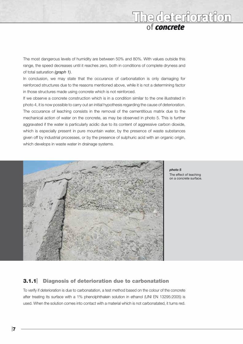
photo 4 Deteriorated structure
due to corrosionof the reinforcement rods.
0 20 40 60 80 100Relative humidity (%)
Rel
ativ
e ca
rbo
nata
tion
spee
d
graph 1 Carbonatation speedcompared with the %
of relative humidity
|7
The deterioration of concrete
photo 5 The effect of leachingon a concrete surface.
The most dangerous levels of humidity are between 50% and 80%. With values outside this
range, the speed decreases until it reaches zero, both in conditions of complete dryness and
of total saturation (graph 1).
In conclusion, we may state that the occurance of carbonatation is only damaging for
reinforced structures due to the reasons mentioned above, while it is not a determining factor
in those structures made using concrete which is not reinforced.
If we observe a concrete construction which is in a condition similar to the one illustrated in
photo 4, it is now possible to carry out an initial hypothesis regarding the cause of deterioration.
The occurance of leaching consists in the removal of the cementitious matrix due to the
mechanical action of water on the concrete, as may be observed in photo 5. This is further
aggravated if the water is particularly acidic due to its content of aggressive carbon dioxide,
which is especially present in pure mountain water, by the presence of waste substances
given off by industrial processes, or by the presence of sulphuric acid with an organic origin,
which develops in waste water in drainage systems.
3.1.1| Diagnosis of deterioration due to carbonatation
To verify if deterioration is due to carbonatation, a test method based on the colour of the concrete
after treating its surface with a 1% phenolphthalein solution in ethanol (UNI EN 13295:2005) is
used. When the solution comes into contact with a material which is not carbonatated, it turns red.
8|
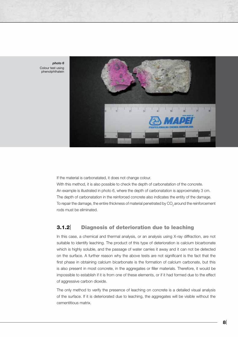
photo 6 Colour test usingphenolphthalein
If the material is carbonatated, it does not change colour.
With this method, it is also possible to check the depth of carbonatation of the concrete.
An example is illustrated in photo 6, where the depth of carbonatation is approximately 3 cm.
The depth of carbonatation in the reinforced concrete also indicates the entity of the damage.
To repair the damage, the entire thickness of material penetrated by CO2 around the reinforcement
rods must be eliminated.
3.1.2| Diagnosis of deterioration due to leaching
In this case, a chemical and thermal analysis, or an analysis using X-ray diffraction, are not
suitable to identify leaching. The product of this type of deterioration is calcium bicarbonate
which is highly soluble, and the passage of water carries it away and it can not be detected
on the surface. A further reason why the above tests are not significant is the fact that the
first phase in obtaining calcium bicarbonate is the formation of calcium carbonate, but this
is also present in most concrete, in the aggregates or filler materials. Therefore, it would be
impossible to establish if it is from one of these elements, or if it had formed due to the effect
of aggressive carbon dioxide.
The only method to verify the presence of leaching on concrete is a detailed visual analysis
of the surface. If it is deteriorated due to leaching, the aggregates will be visible without the
cementitious matrix.
|9
The deterioration of concrete
3.2| Aggression by sulphates
The most common soluble sulphates in the ground, in water and in industrial processes are calcium
and sodium. There are also magnesium sulphates, but these are less common, although they are
more destructive. Sulphate ions may be present in water and in the ground, and they may also
be found directly in the aggregates as impurities. If the sulphates come from the ground or from
the water in contact with the structure, the sulphate ions carried inside the cementitious matrix by
water (fundamental for transportation) reacts with the calcium hydroxide to form gypsum.
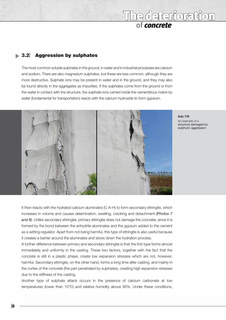
foto 7/8 An example of astructure damaged bysulphuric aggression
It then reacts with the hydrated calcium aluminates (C-A-H) to form secondary ettringite, which
increases in volume and causes delamination, swelling, cracking and detachment (Photos 7
and 8). Unlike secondary ettringite, primary ettringite does not damage the concrete, since it is
formed by the bond between the anhydrite aluminates and the gypsum added to the cement
as a setting regulator. Apart from not being harmful, this type of ettringite is also useful because
it creates a barrier around the aluminates and slows down the hydration process.
A further difference between primary and secondary ettringite is that the first type forms almost
immediately and uniformly in the casting. These two factors, together with the fact that the
concrete is still in a plastic phase, create low expansion stresses which are not, however,
harmful. Secondary ettringite, on the other hand, forms a long time after casting, and mainly in
the cortex of the concrete (the part penetrated by sulphates), creating high expansion stresses
due to the stiffness of the casting.
Another type of sulphate attack occurs in the presence of calcium carbonate at low
temperatures (lower than 10°C) and relative humidity above 95%. Under these conditions,
10|
thaumasite is formed which provokes decalcification and the concrete being reduced to pulp.
Sulphates may also come from within the concrete, in the form of natural impurities in the
aggregates, such as gypsum or anhydrite. The size of the gypsum in the aggregates is higher
compared with the gypsum added to the cement for setting, and is therefore less soluble in
water. This means that it is not immediately available to form primary ettringite, but will later
form secondary ettringite in the cured concrete, causing cracks.
3.2.1| Diagnosis of deterioration due to sulphate attack
To establish whether deterioration of the concrete is due to sulphate attack, chemical analysis
is carried out to measure the level of sulphate present. There is normally a small amount of
calcium sulphate in the concrete, which is added to the cement during the grinding cycle and
acts as a setting regulator. A normal content level in the concrete is around 0.4% to 0.6%.
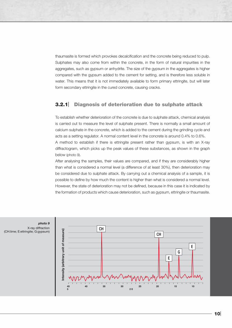
A method to establish if there is ettringite present rather than gypsum, is with an X-ray
diffractogram, which picks up the peak values of these substances, as shown in the graph
below (photo 9).
After analysing the samples, their values are compared, and if they are considerably higher
than what is considered a normal level (a difference of at least 30%), then deterioration may
be considered due to sulphate attack. By carrying out a chemical analysis of a sample, it is
possible to define by how much the content is higher than what is considered a normal level.
However, the state of deterioration may not be defined, because in this case it is indicated by
the formation of products which cause deterioration, such as gypsum, ettringite or thaumasite.
photo 9X-ray diffraction
(CH:lime; E:ettringite; G:gypsum)CH
CH
EG
E
45 40 35 30 25 20 15 10 5 2 θ
Inte
nsity
(arb
itrar
y un
it o
f m
easu
re)
|11
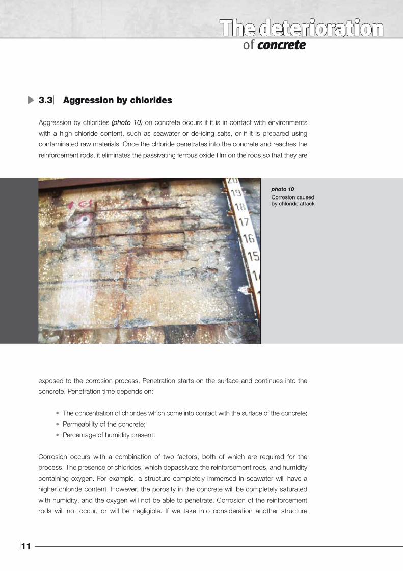
photo 10 Corrosion causedby chloride attack
The deterioration of concrete
3.3| Aggression by chlorides
Aggression by chlorides (photo 10) on concrete occurs if it is in contact with environments
with a high chloride content, such as seawater or de-icing salts, or if it is prepared using
contaminated raw materials. Once the chloride penetrates into the concrete and reaches the
reinforcement rods, it eliminates the passivating ferrous oxide film on the rods so that they are
exposed to the corrosion process. Penetration starts on the surface and continues into the
concrete. Penetration time depends on:
• The concentration of chlorides which come into contact with the surface of the concrete;
• Permeability of the concrete;
• Percentage of humidity present.
Corrosion occurs with a combination of two factors, both of which are required for the
process. The presence of chlorides, which depassivate the reinforcement rods, and humidity
containing oxygen. For example, a structure completely immersed in seawater will have a
higher chloride content. However, the porosity in the concrete will be completely saturated
with humidity, and the oxygen will not be able to penetrate. Corrosion of the reinforcement
rods will not occur, or will be negligible. If we take into consideration another structure
12|
immersed in seawater, the area most exposed to chloride deterioration is the splash zone,
the area which is dry and then wet due to the movement of the waves and high and low
tides. De-icing salts spread on road surfaces during the winter penetrate into the structure
when it rains causing corrosion and deterioration.
Once the process has started, wherever the structure is located, corrosion is faster because
access routes may be found more easily. The concentration of chlorides required to promote
corrosion of the reinforcement rods is directly proportional to the pH of the concrete; the
higher the alkalinity of the concrete, the higher the concentration of chlorides required to start
the process. With reference to this consideration, the phenomenon of deterioration due to
carbonatation may be connected to deterioration by chlorides, in that carbonatation lowers
the pH of the concrete so that even those areas of the structure with a lower concentration
of chlorides will be more vulnerable.
3.3.1| Diagnosis of deterioration due to attack by chlorides
The presence of chlorides may also be verified by a simple laboratory test by chemical analysis.
In this case, chloride of around 0.2% to 0.4% compared with the weight of cement may be
considered normal in concrete. If the level is higher, then the chloride has infiltrated into the
concrete and has damaged it.
Apart from chemical analysis, there are two other tests which may be carried out:
• Colour test, using fluorescein and silver nitrate (UNI 7928 Standards);
• X-ray diffraction analysis.
The first test consists in spraying a core sample with a solution of fluorescein and silver nitrate. A
chemical reaction takes place, and the portion of concrete penetrated by chlorides turns a light
pink colour, while the healthy part turns a dark colour. The line which delimits the colour change
indicates the thickness of deteriorated concrete, and whether the chlorides have reached the
reinforcement rods.
The second test shows the products developed by the chlorides inside the concrete. There are
two types of chlorides from de-icing salts, sodium chloride (NaCl) and calcium chloride (CaCl2).
The first type provokes an alkali-aggregate reaction, and pop-out phenomenon in the floor. The
second test, which is no longer very widely used, causes the formation of oxychloride, a product
which provokes serious deterioration of concrete by removing the cementitious matrix, similar to
deterioration due to leaching.
|13
The deterioration of concrete
3.4| Alkali-aggregates reaction
An alkali-aggregates reaction may cause considerable expansion and serious deterioration of
concrete structures. Some types of aggregate, such as those which contain reactive silicon,
react with two alkalis contained in the cement, potassium and sodium, or as mentioned in
the previous paragraph, with those which come from the surrounding environment in the
form of sodium chloride (NaCl) (de-icing salts or seawater). This reaction forms a gel which is
highly expansive if exposed to humidity, and the gel creates forces which break the concrete
around the aggregates. The alkali-aggregate reaction is a process which takes place slowly and
heterogenously, since it is bound to the composition of the aggregates containing amorphous
silicon. The product of the reaction under such conditions are sodium silicates and hydrated
potassium, which are very voluminous.
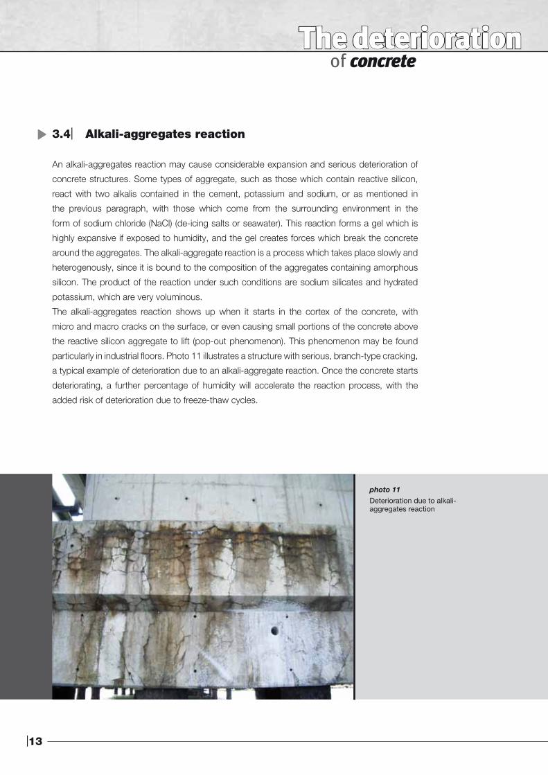
The alkali-aggregates reaction shows up when it starts in the cortex of the concrete, with
micro and macro cracks on the surface, or even causing small portions of the concrete above
the reactive silicon aggregate to lift (pop-out phenomenon). This phenomenon may be found
particularly in industrial floors. Photo 11 illustrates a structure with serious, branch-type cracking,
a typical example of deterioration due to an alkali-aggregate reaction. Once the concrete starts
deteriorating, a further percentage of humidity will accelerate the reaction process, with the
added risk of deterioration due to freeze-thaw cycles.
photo 11Deterioration due to alkali-aggregates reaction
14|
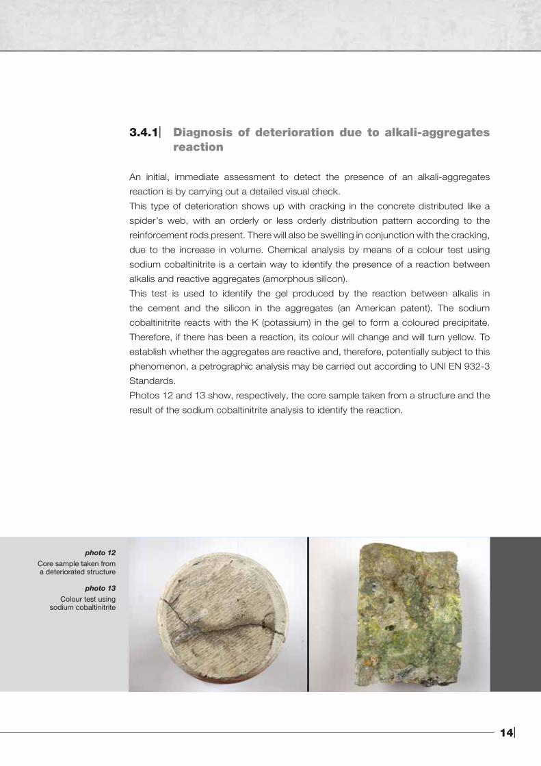
3.4.1| Diagnosis of deterioration due to alkali-aggregates reaction
An initial, immediate assessment to detect the presence of an alkali-aggregates
reaction is by carrying out a detailed visual check.
This type of deterioration shows up with cracking in the concrete distributed like a
spider’s web, with an orderly or less orderly distribution pattern according to the
reinforcement rods present. There will also be swelling in conjunction with the cracking,
due to the increase in volume. Chemical analysis by means of a colour test using
sodium cobaltinitrite is a certain way to identify the presence of a reaction between
alkalis and reactive aggregates (amorphous silicon).
This test is used to identify the gel produced by the reaction between alkalis in
the cement and the silicon in the aggregates (an American patent). The sodium
cobaltinitrite reacts with the K (potassium) in the gel to form a coloured precipitate.
Therefore, if there has been a reaction, its colour will change and will turn yellow. To
establish whether the aggregates are reactive and, therefore, potentially subject to this
phenomenon, a petrographic analysis may be carried out according to UNI EN 932-3
Standards.
Photos 12 and 13 show, respectively, the core sample taken from a structure and the
result of the sodium cobaltinitrite analysis to identify the reaction.
photo 12Core sample taken froma deteriorated structure
photo 13Colour test using
sodium cobaltinitrite
|15
The deterioration of concrete
4| Aggression by physical elements
4.1| Freezing and thawing 4.2| High temperatures 4.3| Shrinkage and cracking
4.1| Freezing and thawing
The effect of ice is negative only in the case of the presence of water at its liquid state inside the
concrete. This does not necessarily mean that the concrete must be perfectly dry, but the level of
humidity must not be higher than a determined level, known as “critical saturation”.
This means that the amount of water present in the porosity must be lower than this value, so
that even when it expands when it turns to ice, it still manages to remain within the pores without
creating stresses. However, if the water fills, or almost fills, the entire volume of the pores, when
it freezes it will break the concrete because of the pressure it exerts (when water turns to ice, its
initial volume increases by 9%).
Also, even if the critical saturation level is not exceeded, the concrete may still be broken due
to the presence of water. If we take into consideration the percentage of water present in all the
concrete, we do not consider the heterogenous distribution of the water inside the casting.
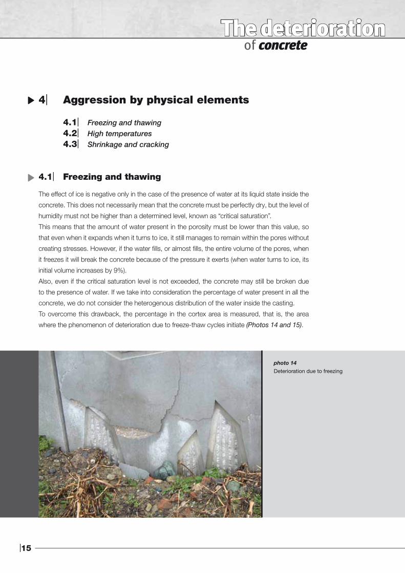
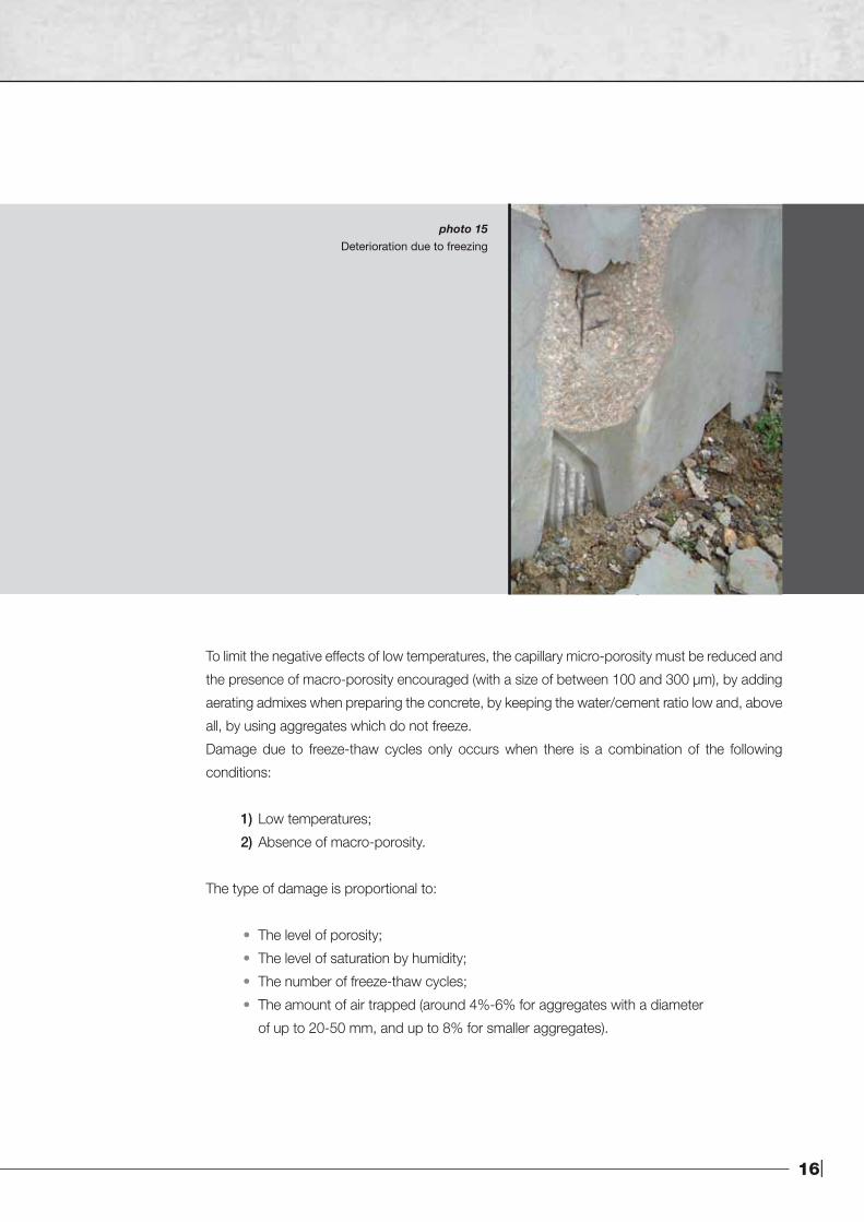
To overcome this drawback, the percentage in the cortex area is measured, that is, the area
where the phenomenon of deterioration due to freeze-thaw cycles initiate (Photos 14 and 15).
photo 14 Deterioration due to freezing
16|
To limit the negative effects of low temperatures, the capillary micro-porosity must be reduced and
the presence of macro-porosity encouraged (with a size of between 100 and 300 µm), by adding
aerating admixes when preparing the concrete, by keeping the water/cement ratio low and, above
all, by using aggregates which do not freeze.
Damage due to freeze-thaw cycles only occurs when there is a combination of the following
conditions:
1) Low temperatures;
2) Absence of macro-porosity.
The type of damage is proportional to:
• The level of porosity;
• The level of saturation by humidity;
• The number of freeze-thaw cycles;
• The amount of air trapped (around 4%-6% for aggregates with a diameter
of up to 20-50 mm, and up to 8% for smaller aggregates).
photo 15 Deterioration due to freezing
|17
The deterioration of concrete
4.2| High temperatures
The effect of high temperatures on concrete is destructive. The reinforcement rods resist
at temperatures of up to 500°C, while concrete resists at up to 650°C. The function of the
concrete around the reinforcement rods in this case is fundamental, in that it slows down
propagation of heat. The thicker the concrete, the longer it takes for the reinforcement rods to
reach their failure temperature of 500°C.
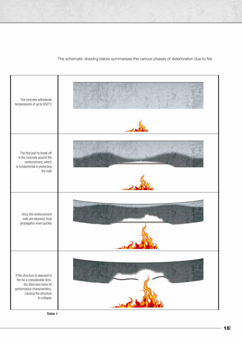
Fire may provoke many types of damage to concrete, and the damage may also be very
serious:
• Even if the reinforcement rods are protected by concrete, when they heat up, their
volume increases and they create stresses in the concrete, this may lead to parts of
the concrete breaking off.
• Once the reinforcement rods are exposed to fire, they expand much more quickly
than the concrete in which they are embedded, causing a loss in adherence and to
them being expelled.
• Even if the failure temperature is not reached, the concrete may lose its performance
characteristics if it is suddenly cooled down, a condition which usually occurs when
fires are extinguished. In this situation, the oxide which forms due to the heat is
transformed into lime, which disintegrates the concrete.
• On the face closest to the fire, spalling takes place due to rapid expansion, and some
of the aggregates explode and may detach the surrounding concrete, the same result
as when humidity is quickly transformed into water vapour, creating small explosions.
• If exposure to fire is prolongued, the reinforcement rods reach their failure temperature
and there is a loss in tensile strength, which causes the entire structure to collapse.
18|
The concrete withstandstemperatures of up to 650°C
The first part to break off is the concrete around the
reinforcement, whichis fundamental in protecting
the rods
Once the reinforcementrods are exposed, heat
propagates more quickly
If the structure is exposed to fire for a considerable time,
the steel also loses its performance characteristics,
causing the structureto collapse
The schematic drawing below summarises the various phases of deterioration due to fire.
Table 1
|19
The deterioration of concrete
4.3| Shrinkage and cracking
This section discusses two types of shrinkage, plastic and hygrometric. Plastic shrinkage
occurs during the plastic phase of concrete, when it releases part of the humidity contained
within it into the surrounding environment, causing it to contract. Cracking in this case depends
on the surrounding conditions when the concrete is cast. When cast into formwork, for obvious
reasons, evaporation does not take place, whereas if the concrete is in direct contact with the
surrounding environment, evaporation occurs because of the temperature, very low external
humidity or strong winds. When plastic shrinkage occurs while the concrete is fresh, micro-
cracks may form on the surface. Hygrometric shrinkage is due to the release of humidity into the
environment with a low level of R.H. during the entire service life of the structure.
In order to avoid the problems due to plastic shrinkage, precautions must be taken to avoid the
water present in the mix evaporating too quickly, which may be done in various ways:
1) By laying waterproof sheets on the casting, to block evaporation
2) By spraying the entire surface during the first few days after casting
3) By applying a protective anti-evaporation filming product on the concrete while still fresh
Since the large majority of hygrometric shrinkage takes place within the first six months of
casting, it is impossible to keep it wet for the entire duration. Therefore, we must act upon other
factors, such as reducing the water/cement ratio and increasing the inert/cement ratio.
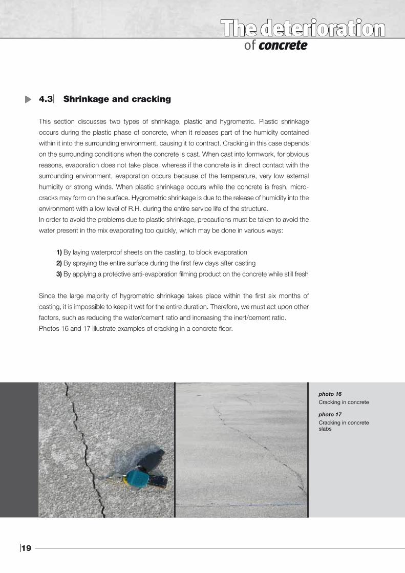
Photos 16 and 17 illustrate examples of cracking in a concrete floor.
photo 16Cracking in concrete
photo 17Cracking in concreteslabs
20|
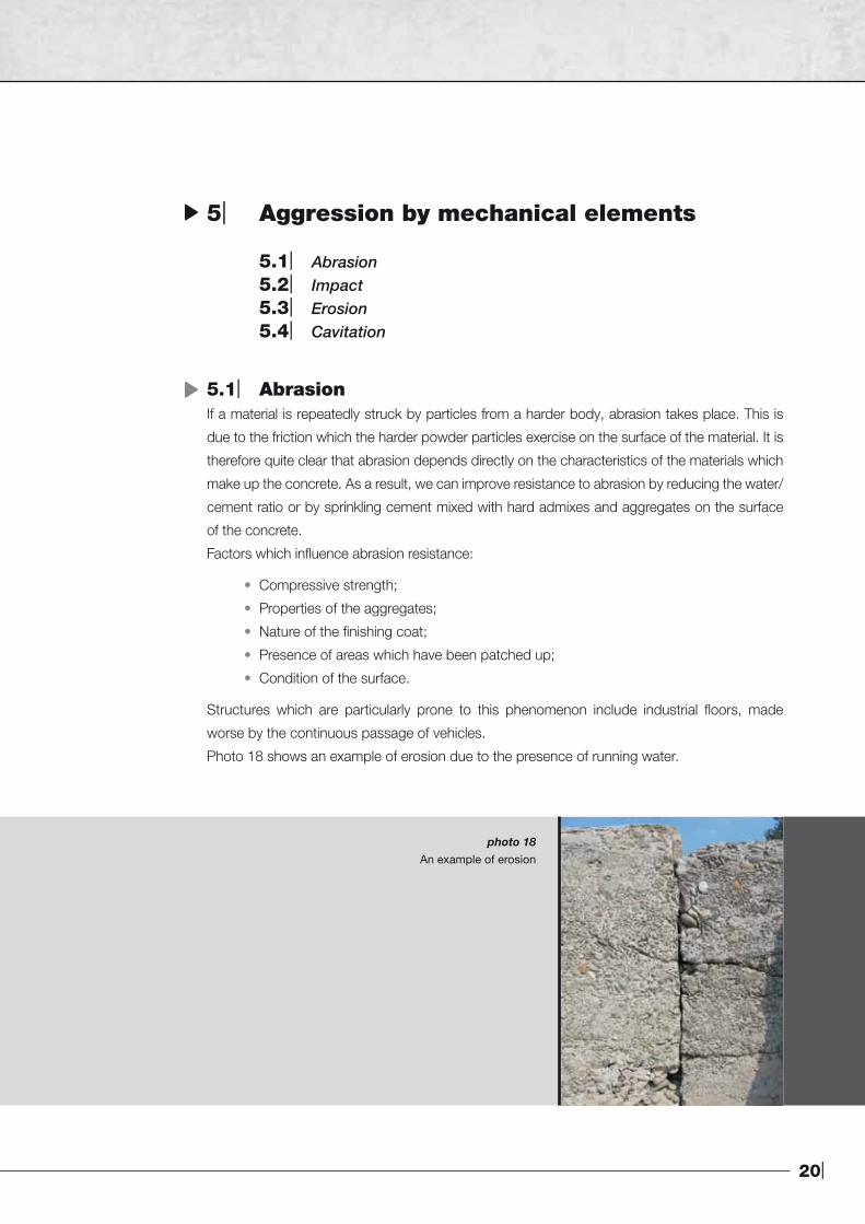
photo 18An example of erosion
5| Aggression by mechanical elements
5.1| Abrasion 5.2| Impact 5.3| Erosion 5.4| Cavitation
5.1| AbrasionIf a material is repeatedly struck by particles from a harder body, abrasion takes place. This is
due to the friction which the harder powder particles exercise on the surface of the material. It is
therefore quite clear that abrasion depends directly on the characteristics of the materials which
make up the concrete. As a result, we can improve resistance to abrasion by reducing the water/
cement ratio or by sprinkling cement mixed with hard admixes and aggregates on the surface
of the concrete.
Factors which influence abrasion resistance:
• Compressive strength;
• Properties of the aggregates;
• Nature of the finishing coat;
• Presence of areas which have been patched up;
• Condition of the surface.
Structures which are particularly prone to this phenomenon include industrial floors, made
worse by the continuous passage of vehicles.
Photo 18 shows an example of erosion due to the presence of running water.
|21
The deterioration of concrete
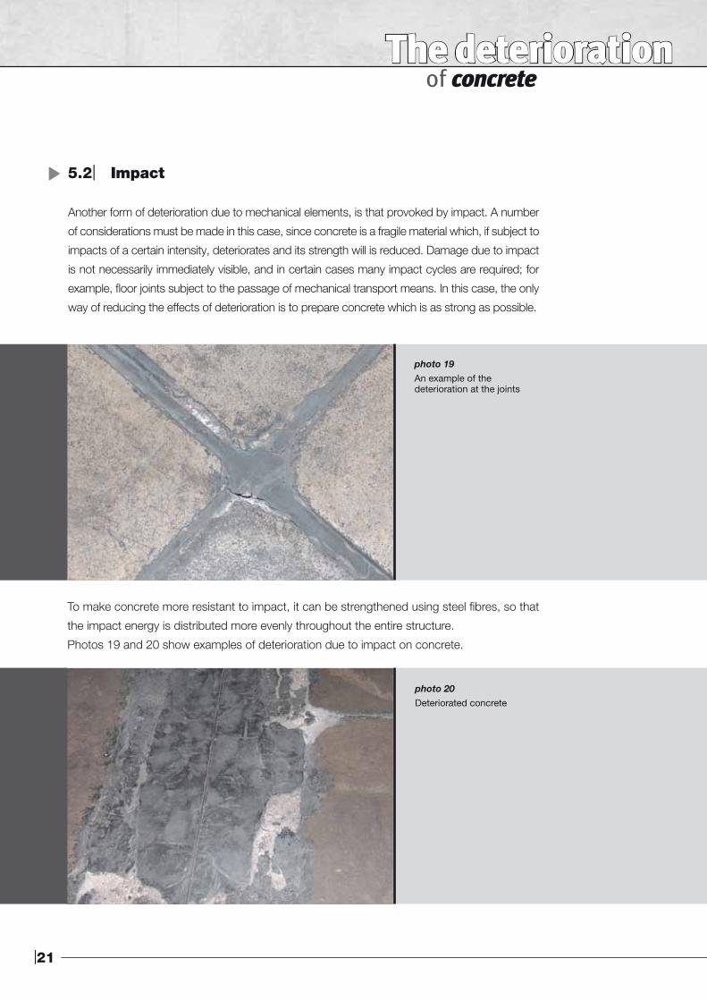
photo 19 An example of thedeterioration at the joints
5.2| Impact
Another form of deterioration due to mechanical elements, is that provoked by impact. A number
of considerations must be made in this case, since concrete is a fragile material which, if subject to
impacts of a certain intensity, deteriorates and its strength will is reduced. Damage due to impact
is not necessarily immediately visible, and in certain cases many impact cycles are required; for
example, floor joints subject to the passage of mechanical transport means. In this case, the only
way of reducing the effects of deterioration is to prepare concrete which is as strong as possible.
To make concrete more resistant to impact, it can be strengthened using steel fibres, so that
the impact energy is distributed more evenly throughout the entire structure.
Photos 19 and 20 show examples of deterioration due to impact on concrete.
photo 20 Deteriorated concrete
22|
5.3| Erosion
Erosion is a particular form of wear due to wind, water or ice which provokes the removal of
material from the surface. It depends on the speed, the content of hard dust particles and the
quality of the concrete. In this case, the only remedy is to take special care when mixing the
concrete. The same guidelines as for abrasion should be followed.
5.4| Cavitation
Cavitation is a problem where flowing water (> 12 m/s) is present. The high speed of the water,
together with an irregular surface where the water flows, provoke turbulence and areas of low
pressure, and vortexes will form which erode the substrate. The air bubbles which form in the
water flow downstream, and when they run into an area of high pressure, implode and cause
a strong impact, resulting in erosion. If the speed of the water is particularly high, erosion due
to cavitation may be serious. The occurance of cavitation may be avoided by laying smooth
surfaces without obstacles along the water course.
6| Defects
Concrete is a mixture of a number of elements. The way it is prepared depends on each
project’s single requirements; the higher the requirements, the more delicate the design of the
mix will be. The main components are cement, aggregates, water and admixtures. If any of
these elements are used incorrectly, one or more weak points in the concrete could develop.
If we consider a case where the best products available on the market are used, but due to a
lack of experience, or for any of a number of other reasons, they are blended together using
incorrect mixing ratios, the result will be the same as if poorer quality products had been used.
The quality of the materials used is vitally important, but it is even more crucial that they are
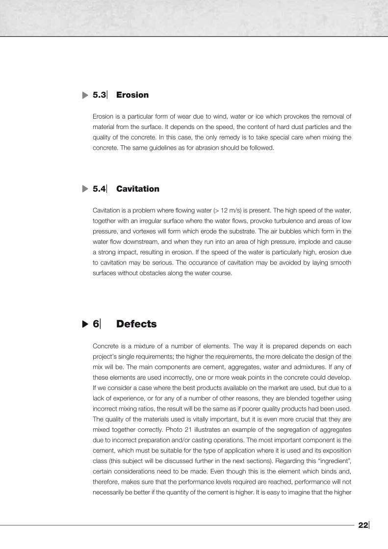
mixed together correctly. Photo 21 illustrates an example of the segregation of aggregates
due to incorrect preparation and/or casting operations. The most important component is the
cement, which must be suitable for the type of application where it is used and its exposition
class (this subject will be discussed further in the next sections). Regarding this “ingredient”,
certain considerations need to be made. Even though this is the element which binds and,
therefore, makes sure that the performance levels required are reached, performance will not
necessarily be better if the quantity of the cement is higher. It is easy to imagine that the higher
|23
The deterioration of concrete
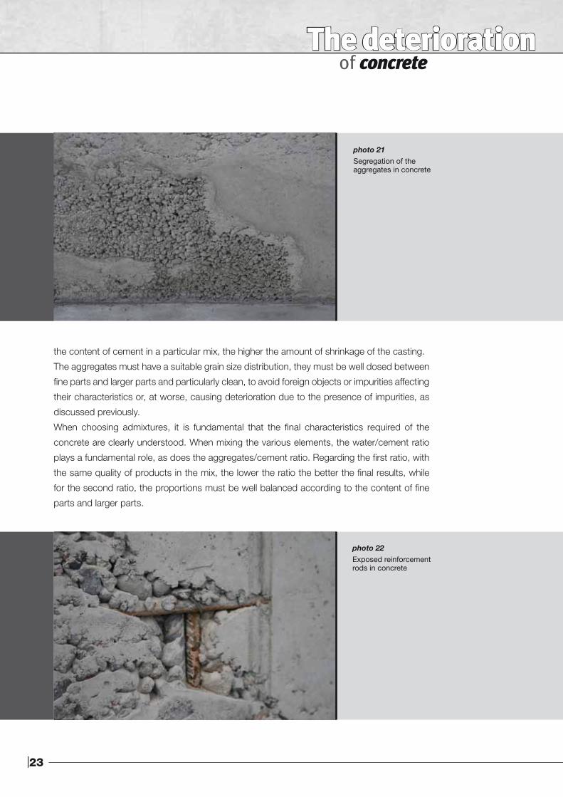
photo 21 Segregation of theaggregates in concrete
the content of cement in a particular mix, the higher the amount of shrinkage of the casting.
The aggregates must have a suitable grain size distribution, they must be well dosed between
fine parts and larger parts and particularly clean, to avoid foreign objects or impurities affecting
their characteristics or, at worse, causing deterioration due to the presence of impurities, as
discussed previously.
When choosing admixtures, it is fundamental that the final characteristics required of the
concrete are clearly understood. When mixing the various elements, the water/cement ratio
plays a fundamental role, as does the aggregates/cement ratio. Regarding the first ratio, with
the same quality of products in the mix, the lower the ratio the better the final results, while
for the second ratio, the proportions must be well balanced according to the content of fine
parts and larger parts.
photo 22Exposed reinforcementrods in concrete
24|
In photo 22, apart from the evident segregation of the aggregates, we can also see the exposed
reinforcement rods, a symptom of incorrect casting of the concrete. If the reinforcement rods
are not protected sufficiently by the concrete, problems due to the penetration of agents
which cause deterioration will be provoked more easily.
To summarise the defects in concrete, they may be divided into three main categories:
• Defects due to poor/incorrect deign of the mix;
• Defects due to the wrong composition;
• Defects due to incorrect/poor quality installation.
|25
The deterioration of concrete
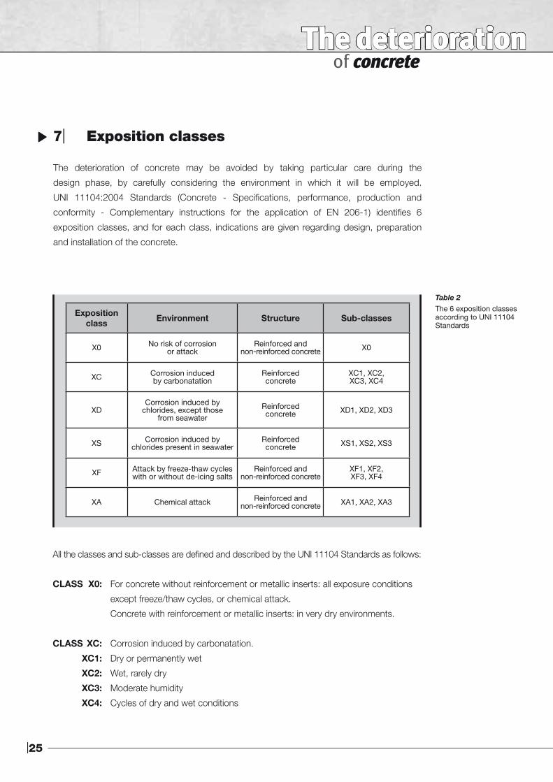
7| Exposition classes
The deterioration of concrete may be avoided by taking particular care during the
design phase, by carefully considering the environment in which it will be employed.
UNI 11104:2004 Standards (Concrete - Specifications, performance, production and
conformity - Complementary instructions for the application of EN 206-1) identifies 6
exposition classes, and for each class, indications are given regarding design, preparation
and installation of the concrete.
All the classes and sub-classes are defined and described by the UNI 11104 Standards as follows:
CLASS X0: For concrete without reinforcement or metallic inserts: all exposure conditions
except freeze/thaw cycles, or chemical attack.
Concrete with reinforcement or metallic inserts: in very dry environments.
CLASS XC: Corrosion induced by carbonatation.
XC1: Dry or permanently wet
XC2: Wet, rarely dry
XC3: Moderate humidity
XC4: Cycles of dry and wet conditions
Exposition class Environment Structure Sub-classes
X0 No risk of corrosionor attack
Reinforced andnon-reinforced concrete X0
XC Corrosion inducedby carbonatation
Reinforcedconcrete
XC1, XC2, XC3, XC4
XDCorrosion induced by
chlorides, except thosefrom seawater
Reinforcedconcrete XD1, XD2, XD3
XS Corrosion induced bychlorides present in seawater
Reinforcedconcrete XS1, XS2, XS3
XF Attack by freeze-thaw cycles with or without de-icing salts
Reinforced andnon-reinforced concrete
XF1, XF2, XF3, XF4
XA Chemical attack Reinforced andnon-reinforced concrete XA1, XA2, XA3
Table 2The 6 exposition classesaccording to UNI 11104Standards
26|
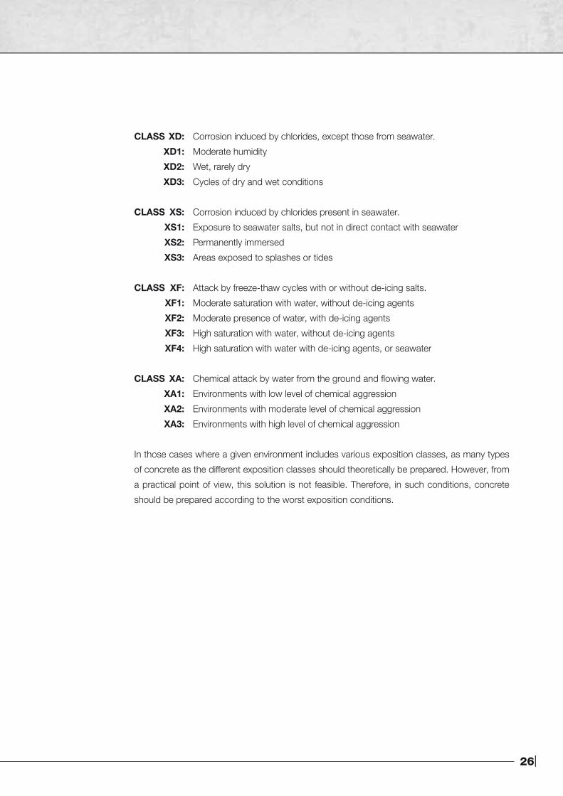
CLASS XD: Corrosion induced by chlorides, except those from seawater.
XD1: Moderate humidity
XD2: Wet, rarely dry
XD3: Cycles of dry and wet conditions
CLASS XS: Corrosion induced by chlorides present in seawater.
XS1: Exposure to seawater salts, but not in direct contact with seawater
XS2: Permanently immersed
XS3: Areas exposed to splashes or tides
CLASS XF: Attack by freeze-thaw cycles with or without de-icing salts.
XF1: Moderate saturation with water, without de-icing agents
XF2: Moderate presence of water, with de-icing agents
XF3: High saturation with water, without de-icing agents
XF4: High saturation with water with de-icing agents, or seawater
CLASS XA: Chemical attack by water from the ground and flowing water.
XA1: Environments with low level of chemical aggression
XA2: Environments with moderate level of chemical aggression
XA3: Environments with high level of chemical aggression
In those cases where a given environment includes various exposition classes, as many types
of concrete as the different exposition classes should theoretically be prepared. However, from
a practical point of view, this solution is not feasible. Therefore, in such conditions, concrete
should be prepared according to the worst exposition conditions.
|27
The deterioration of concrete
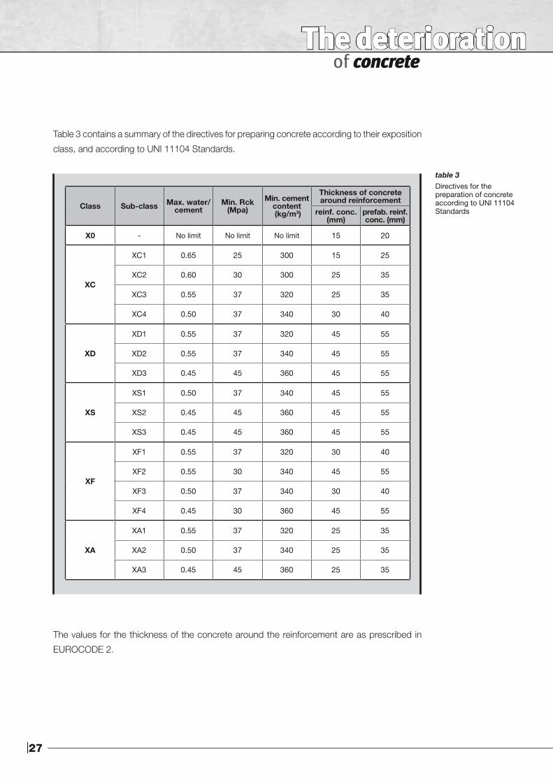
Table 3 contains a summary of the directives for preparing concrete according to their exposition
class, and according to UNI 11104 Standards.
Class Sub-class Max. water/cement
Min. Rck (Mpa)
Min. cement content (kg/m3)
Thickness of concrete around reinforcement
reinf. conc. (mm)
prefab. reinf. conc. (mm)
X0 - No limit No limit No limit 15 20
XC
XC1 0.65 25 300 15 25
XC2 0.60 30 300 25 35
XC3 0.55 37 320 25 35
XC4 0.50 37 340 30 40
XD
XD1 0.55 37 320 45 55
XD2 0.55 37 340 45 55
XD3 0.45 45 360 45 55
XS
XS1 0.50 37 340 45 55
XS2 0.45 45 360 45 55
XS3 0.45 45 360 45 55
XF
XF1 0.55 37 320 30 40
XF2 0.55 30 340 45 55
XF3 0.50 37 340 30 40
XF4 0.45 30 360 45 55
XA
XA1 0.55 37 320 25 35
XA2 0.50 37 340 25 35
XA3 0.45 45 360 25 35
The values for the thickness of the concrete around the reinforcement are as prescribed in
EUROCODE 2.
table 3Directives for thepreparation of concreteaccording to UNI 11104Standards

28|
Notes:
The deterioration of concrete
Notes: