Embed Size (px)
Citation preview

A study of the geometry and parameter dependence of vortex breakdownM. C. Jones, K. Hourigan, and M. C. Thompson Citation: Physics of Fluids (1994-present) 27, 044102 (2015); doi: 10.1063/1.4916352 View online: http://dx.doi.org/10.1063/1.4916352 View Table of Contents: http://scitation.aip.org/content/aip/journal/pof2/27/4?ver=pdfcov Published by the AIP Publishing Articles you may be interested in Interaction of viscous and inviscid instability modes in separation–bubble transition Phys. Fluids 23, 124102 (2011); 10.1063/1.3666844 Control of axisymmetric vortex breakdown in a constricted pipe: Nonlinear steady states and weaklynonlinear asymptotic expansions Phys. Fluids 23, 084102 (2011); 10.1063/1.3610380 Three-dimensional transitions in a swirling jet impinging against a solid wall at moderate Reynoldsnumbers Phys. Fluids 21, 034107 (2009); 10.1063/1.3103364 On the development of three-dimensional vortex breakdown in cylindrical regions Phys. Fluids 18, 084105 (2006); 10.1063/1.2338065 Numerical simulation of bubble-type vortex breakdown within a tube-and-vane apparatus Phys. Fluids 12, 603 (2000); 10.1063/1.870266
This article is copyrighted as indicated in the article. Reuse of AIP content is subject to the terms at: http://scitation.aip.org/termsconditions. Downloaded
to IP: 58.175.18.214 On: Mon, 06 Apr 2015 23:54:27
PHYSICS OF FLUIDS 27, 044102 (2015)
A study of the geometry and parameter dependenceof vortex breakdown
M. C. Jones,1,a) K. Hourigan,1,2 and M. C. Thompson11Fluids Laboratory for Aeronautical and Industrial Research (FLAIR), Departmentof Mechanical and Aerospace Engineering, Monash University, Melbourne, Australia2Laboratory for Biomedical Engineering, Monash University, Melbourne, Australia
(Received 26 July 2014; accepted 3 March 2015; published online 3 April 2015)
The types of vortex breakdown observed in the torsionally driven cylinder (TDC)flow and in the flow through an open-ended pipe are compared. The connectionbetween the various breakdown types is specifically addressed, and the differencesin manifestation of breakdown are attributed to the different Reynolds number re-gimes involved. Here, in both cases, the Reynolds number is based on quantitiesassociated with the vortex core immediately upstream of breakdown, rather thanthe more geometry-specific Reynolds number defined in the previous work. Thus,the relationship between the TDC flow and the flows observed in other, more opengeometries, is clarified. The predominantly asymmetric breakdown observed in openhigh Reynolds number flows is replaced by a closed bubble form with decreasingReynolds number in the TDC. Three-dimensional numerical simulations supportthis interpretation, showing that the 3D spiral type of breakdown is replaced bya TDC-type axisymmetric breakdown in an open pipe as the Reynolds numberis reduced. The stability of the three-dimensional solutions indicates that spiralbreakdown modes stabilise at lower Reynolds number, leading to an axisymmetricbreakdown state as a stable evolved flow solution. C 2015 AIP Publishing LLC.[http://dx.doi.org/10.1063/1.4916352]
I. INTRODUCTION
Recent years have seen an increasing interest in vortex breakdown, due to its association withhighly manoeuvrable aircraft, which continue to adopt variants of the delta wing planform. Break-down has long been associated with the highly swept delta planform of the F/A-18 leading-edgeextension, for example, and the effect of breakdown for this aircraft, in particular, is well known: theunsteadiness downstream of breakdown leads to tail buffetting and hence increased fatigue. Some ofthe next generation of proposed unmanned combat air vehicles and micro-air vehicles also have adelta planform, often with lower sweep. Lower sweep results in an increased propensity toward theappearance of vortex breakdown. Since these aircraft will be capable of extreme manoeuvres wherebreakdown can manifest, the phenomenon must be considered as part of the aerodynamics of suchwings (Gursul, Gordnier, and Visbal1).
Breakdown can also be observed in the swirling flow in a confined cylinder. The mixingproperties of the flow in a confined cylinder have practical importance for cell culture and tissueengineering following initial experimental investigations,2,3 computational studies,4–10 and cell cul-ture.11 The structure and stability of the vortex breakdown bubble in such bioreactors has importantimplications for the rate of nutrient transfer and waste disposal, and whether the vortex breakdownbubble itself could be used as a “virtual reactor” in which constructs such as scaffolds could beplaced or cells cultured.
The measures which have thus far been applied to control vortex breakdown have relied onmanipulation of parameters that have long been known to influence breakdown. These parameters
a)Present address: Equos Research Co., Ltd., Anjo, Japan.
1070-6631/2015/27(4)/044102/13/$30.00 27, 044102-1 ©2015 AIP Publishing LLC
This article is copyrighted as indicated in the article. Reuse of AIP content is subject to the terms at: http://scitation.aip.org/termsconditions. Downloaded
to IP: 58.175.18.214 On: Mon, 06 Apr 2015 23:54:27
044102-2 Jones, Hourigan, and Thompson Phys. Fluids 27, 044102 (2015)
include the swirl level of the base vortical flow and the pressure gradient (up to a limit, high swirland an adverse pressure gradient promote the onset of breakdown). One review of the progressmade in breakdown control is Mitchell and Delery,12 and research into control methods is continu-ing.13–17 Despite the significant control demonstrated however, these methods appear not to havecontributed to breakdown control in practice. The current solution for the F/A-18, for instance, isthe placement of a vortex generator on the surface of the leading-edge extension to divert the vortexoutboard of the vertical stabilizers, where breakdown when it does occur can do less harm.
In addition to studies of breakdown control, theoretical research has contributed much to theunderstanding of the mechanism for breakdown. It is now widely considered that breakdown resultsfrom the waveguide nature of vortical flows, as described by Benjamin.18 In this context, breakdownhas been associated with a point where the vortex core becomes capable of supporting upstreamtravelling disturbances. At this point, disturbances on the vortex core “pile up,” resulting in expansionof the vortex, and eventually stagnation and the formation of a recirculation region in the case of thebubble form of breakdown. A description of this model is given by Randall and Leibovich.19 Therelationship between this mechanism and the stability of the flow is described in Wang and Rusak20
and Rusak, Whiting, and Wang.21 In addition, the generation of negative azimuthal vorticity has beenshown to be a necessary condition for the onset of breakdown,22,23 and Darmofal and Murman24
described the generation of this negative azimuthal vorticity by disturbance trapping.The description of a mechanism for breakdown is complicated by the fact that a number
of different flow phenomena have been described as breakdown. The experimental study of aswirling jet by Billant, Chomaz, and Huerre25 revealed both axisymmetric and asymmetric bubbleand conical structures. Asymmetry was shown to occur at higher Reynolds number relative tothe axisymmetric forms. A stability analysis26 of this flow predicted the onset of a double helixstructure at a swirl below that required for breakdown, and the double helix was observed in theexperiments. However, the analysis could not predict the axisymmetric bubble mode also observedexperimentally. In a later study,27 the spiral form of breakdown, which is often observed down-stream of the bubble form, was shown to be associated with a global instability in the wake of theaxisymmetric bubble.28
In a study of more direct relevance to aeronautical flows, Rusak and Lamb29 showed that break-down onset over slender delta wings could be predicted from the swirl ratio of the leading-edgevortex. The linear stability and critical state analyses of Renac and Jacquin30 indicated that fordelta wings, disturbances upstream of breakdown are either damped or weakly amplified, and thatdownstream of breakdown, asymmetric modes are amplified. This supported the previous workthat indicated a role for instability in the transition to asymmetric breakdown,27 but not for theaxisymmetric (bubble) mode.
In contrast to that work, studies of the mechanism for breakdown are generally conducted atmuch lower Reynolds numbers, and for very different geometries, compared with the typical flightregime for real aircraft. The behaviour of breakdown in simplified geometries at very low Reynoldsnumber is significantly different to the behaviour observed over real wings. As discussed in Herradaand Fernandez-Feria31 at low Reynolds number in the torsionally driven cylinder (TDC), the break-down form is axisymmetric, but at higher Reynolds number (for example, over delta wings), break-down is predominantly asymmetric. (Some observations of asymmetric breakdown in the TDC at lowReynolds number have been reported. Experiments and calculations have indicated that very slightasymmetries in the TDC geometry, i.e., very slight structural asymmetries, can lead to clearly asym-metric flows.32,33 In addition, slight visualisation technique asymmetries, such as slight misalign-ments in dye injection34 and dye diffusion35 can lead to strongly asymmetric visualisations even forstrictly symmetric flows. The onset of precession of the breakdown bubbles in the TDC has, however,been observed for high Reynolds numbers36,37 and at cylinder aspect ratios above 3.3, asymmetryhas also been observed.38,39
The different observations of breakdown in the low Reynolds number confined flows, and thehigh Reynolds number open flows, have caused some to question the relationship between thebreakdowns observed in these different situations. Importantly, although there may be some degreeof implicit understanding of the relationship between different breakdown states by experiencedworkers in the field, to the authors’ knowledge, few papers have specifically addressed the reasons
This article is copyrighted as indicated in the article. Reuse of AIP content is subject to the terms at: http://scitation.aip.org/termsconditions. Downloaded
to IP: 58.175.18.214 On: Mon, 06 Apr 2015 23:54:27
044102-3 Jones, Hourigan, and Thompson Phys. Fluids 27, 044102 (2015)
for the different manifestations. The intention here is to directly address this issue, and both clarifyand quantify the relationship between the various breakdown forms observed.
We suggest that the relationship between the TDC and open flows can be more easily under-stood using parameters that are more consistently related to the physical conditions leading tobreakdown. In the current work, we directly compare the various flows which support breakdownusing such parameters. Following this, we show how observations of symmetric breakdown in theTDC follow from the much lower effective Reynolds number of the TDC flow, as confirmed bythe observation that reducing the Reynolds number in a pipe to a level similar to that in the TDC,the asymmetry in that geometry also disappears.
The analysis proceeds as follows:
1. The nature of the flows resulting in breakdown in open pipe and TDC geometries are comparedinitially by examining the flow upstream of breakdown.
2. More appropriate definitions of Reynolds number and swirl are proposed to allow more directcomparison of the TDC and open pipe flows.
3. In light of the above analysis, the variation in breakdown observations between geometries isdiscussed.
4. A final three-dimensional modelling exercise of a pipe flow at very low Reynolds number isused to confirm the main assertions.
II. NUMERICAL METHOD
Variants of spectral-element codes were used for the simulations. These codes have been exten-sively validated previously so only brief descriptions will be provided here, with further detailsfound in the articles referenced.
A. Steady axisymmetric code
Steady axisymmetric flows were computed using an axisymmetric steady solver based on New-ton iteration and enforcing continuity using the penalty approach.40 Within each spectral element,the internal nodes are distributed based on the Gauss-Legendre-Lobatto quadrature points, with flowvariables represented through tensor-product Lagrange polynomial expansions, and in turn GLLquadrature is used to evaluate the integrals from the application of the weighted residual method.The number of internal nodes can be chosen at runtime, allowing resolution studies to be conductedto verify the predictions are converged. This method has been previously applied to flows withvortex breakdown in Thompson and Hourigan.32
B. Spectral/spectral-element code
For the three-dimensional pipe calculations, a spectral/spectral-element method was used.The method is described in Thompson, Hourigan, and Sheridan41 and a more detailed descrip-tion of the formulation of the spectral-element method can be found in the study by Karni-adakis and Triantafyllou.42 The aim of the technique is to balance the superior convergence ofhigher-order global spectral methods with the ability to model a greater variety of geometries.For the pipe geometry considered here, solutions in an axial-radial plane can be obtained using atwo-dimensional spectral element mesh. For each element, high-order Lagrangian polynomial inter-polation is used to represent the spatial variation of the solution variables. The method is extendedto three dimensions by the addition of a Fourier spectral decomposition in the azimuthal direction.Time integration is performed in three steps, accounting for convection, pressure, and diffusionterms. The third-order Adams-Bashforth method is employed for the convection equation, and theCrank-Nicholson scheme for the diffusion equation. To evaluate the pressure, the divergence of theequation for the pressure substep is taken, and continuity is enforced at the completion of eachtimestep. More details on the general method and application to similar problems can be found inthe following papers: Thompson et al.,43 Griffith et al.,44 Stewart et al.,45 and Thompson, Leweke,and Provansal.46
This article is copyrighted as indicated in the article. Reuse of AIP content is subject to the terms at: http://scitation.aip.org/termsconditions. Downloaded
to IP: 58.175.18.214 On: Mon, 06 Apr 2015 23:54:27
044102-4 Jones, Hourigan, and Thompson Phys. Fluids 27, 044102 (2015)
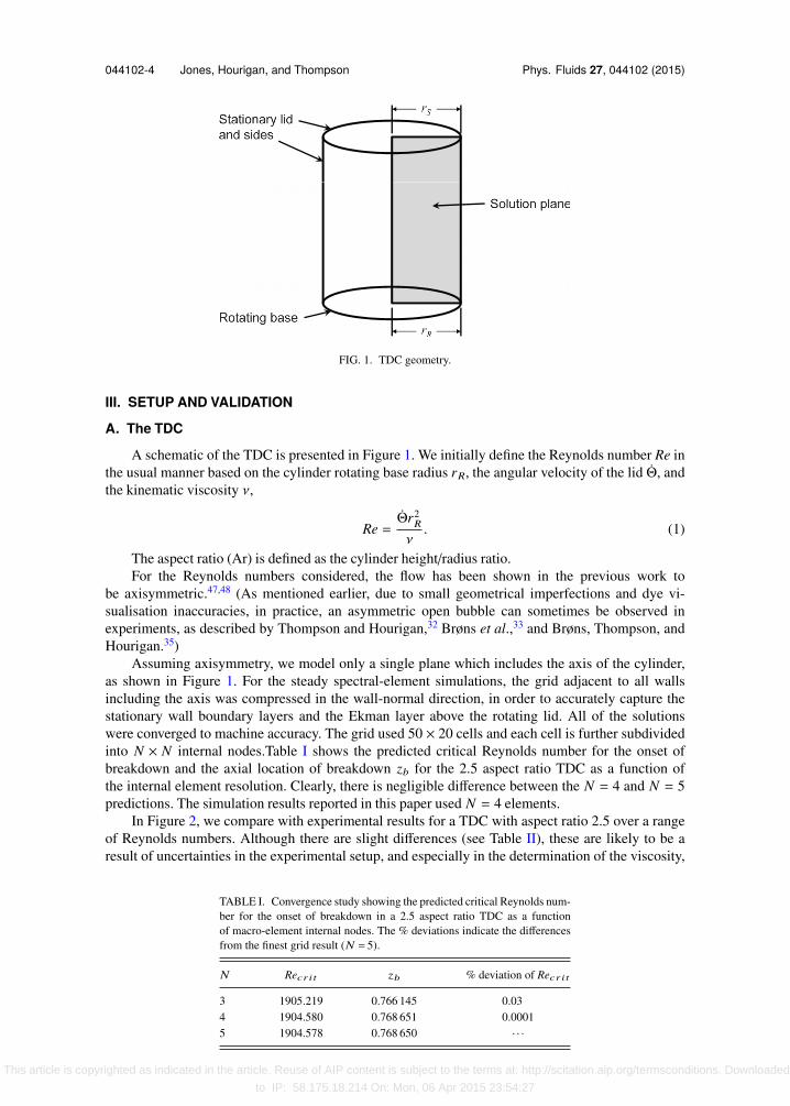
FIG. 1. TDC geometry.
III. SETUP AND VALIDATION
A. The TDC
A schematic of the TDC is presented in Figure 1. We initially define the Reynolds number Re inthe usual manner based on the cylinder rotating base radius rR, the angular velocity of the lid Θ, andthe kinematic viscosity ν,
Re =Θr2
R
ν. (1)
The aspect ratio (Ar) is defined as the cylinder height/radius ratio.For the Reynolds numbers considered, the flow has been shown in the previous work to
be axisymmetric.47,48 (As mentioned earlier, due to small geometrical imperfections and dye vi-sualisation inaccuracies, in practice, an asymmetric open bubble can sometimes be observed inexperiments, as described by Thompson and Hourigan,32 Brøns et al.,33 and Brøns, Thompson, andHourigan.35)
Assuming axisymmetry, we model only a single plane which includes the axis of the cylinder,as shown in Figure 1. For the steady spectral-element simulations, the grid adjacent to all wallsincluding the axis was compressed in the wall-normal direction, in order to accurately capture thestationary wall boundary layers and the Ekman layer above the rotating lid. All of the solutionswere converged to machine accuracy. The grid used 50 × 20 cells and each cell is further subdividedinto N × N internal nodes.Table I shows the predicted critical Reynolds number for the onset ofbreakdown and the axial location of breakdown zb for the 2.5 aspect ratio TDC as a function ofthe internal element resolution. Clearly, there is negligible difference between the N = 4 and N = 5predictions. The simulation results reported in this paper used N = 4 elements.
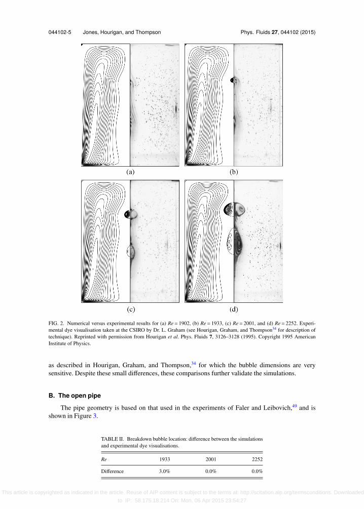
In Figure 2, we compare with experimental results for a TDC with aspect ratio 2.5 over a rangeof Reynolds numbers. Although there are slight differences (see Table II), these are likely to be aresult of uncertainties in the experimental setup, and especially in the determination of the viscosity,
TABLE I. Convergence study showing the predicted critical Reynolds num-ber for the onset of breakdown in a 2.5 aspect ratio TDC as a functionof macro-element internal nodes. The % deviations indicate the differencesfrom the finest grid result (N = 5).
N Recr it zb % deviation of Recr it
3 1905.219 0.766 145 0.034 1904.580 0.768 651 0.00015 1904.578 0.768 650 · · ·
This article is copyrighted as indicated in the article. Reuse of AIP content is subject to the terms at: http://scitation.aip.org/termsconditions. Downloaded
to IP: 58.175.18.214 On: Mon, 06 Apr 2015 23:54:27
044102-5 Jones, Hourigan, and Thompson Phys. Fluids 27, 044102 (2015)
FIG. 2. Numerical versus experimental results for (a) Re= 1902, (b) Re= 1933, (c) Re= 2001, and (d) Re= 2252. Experi-mental dye visualisation taken at the CSIRO by Dr. L. Graham (see Hourigan, Graham, and Thompson34 for description oftechnique). Reprinted with permission from Hourigan et al. Phys. Fluids 7, 3126–3128 (1995). Copyright 1995 AmericanInstitute of Physics.
as described in Hourigan, Graham, and Thompson,34 for which the bubble dimensions are verysensitive. Despite these small differences, these comparisons further validate the simulations.
B. The open pipe
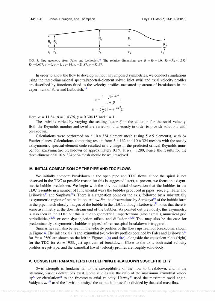
The pipe geometry is based on that used in the experiments of Faler and Leibovich,49 and isshown in Figure 3.
TABLE II. Breakdown bubble location: difference between the simulationsand experimental dye visualisations.
Re 1933 2001 2252
Difference 3.0% 0.0% 0.0%
This article is copyrighted as indicated in the article. Reuse of AIP content is subject to the terms at: http://scitation.aip.org/termsconditions. Downloaded
to IP: 58.175.18.214 On: Mon, 06 Apr 2015 23:54:27
044102-6 Jones, Hourigan, and Thompson Phys. Fluids 27, 044102 (2015)
FIG. 3. Pipe geometry from Faler and Leibovich.49 The relative dimensions are R1= R2= 1.0, R3= R4= 1.333,R5= 0.667; z1= 0, z2= 1, z3= 14, z4= 21.87, z5= 32.37.
In order to allow the flow to develop without any imposed symmetries, we conduct simulationsusing the three-dimensional spectral/spectral-element solver. Inlet swirl and axial velocity profilesare described by functions fitted to the velocity profiles measured upstream of breakdown in theexperiment of Faler and Leibovich,49
u =1 + βe−αr
2
1 + β,
w = ζγ
r(1 − e−αr
2).Here, α = 11.84, β = 1.4376, γ = 0.304 15, and ζ = 1.
The swirl is varied by varying the scaling factor ζ in the equation for the swirl velocity.Both the Reynolds number and swirl are varied simultaneously in order to provide solutions withbreakdown.
Calculations were performed on a 10 × 324 element mesh (using 5 × 5 elements), with 64Fourier planes. Calculations comparing results from 5 × 162 and 10 × 324 meshes with the steadyaxisymmetric spectral-element code resulted in a change in the predicted critical Reynolds num-ber for axisymmetric breakdown of approximately 0.1% at Re = 1280, hence the results for thethree-dimensional 10 × 324 × 64 mesh should be well resolved.
IV. INITIAL COMPARISON OF THE PIPE AND TDC FLOWS
We initially compare breakdown in the open pipe and TDC flows. Since the spiral is notobserved in the TDC (a possible reason for this is suggested later), at present, we focus on axisym-metric bubble breakdown. We begin with the obvious initial observation that the bubbles in theTDC resemble in a number of fundamental ways the bubbles produced in pipes (see, e.g., Faler andLeibovich49 and Sarpkaya50). There is a stagnation point on the axis, followed by a substantiallyaxisymmetric region of recirculation. At low Re, the observations by Sarpkaya50 of the bubble formin the pipe match closely images of the bubble in the TDC, although Leibovich51 notes that there issome asymmetry at the downstream end of the bubbles. As pointed out previously, this asymmetryis also seen in the TDC, but this is due to geometrical imperfections (albeit small), numerical gridperiodicities,32,33 or even dye injection offsets and diffusion.34,35 This may also be the case forpredominantly axisymmetric bubbles in pipes before true spiral breakdown is triggered.
Similarities can also be seen in the velocity profiles of the flows upstream of breakdown, shownin Figure 4. The inlet axial (u) and azimuthal (w) velocity profiles obtained by Faler and Leibovich52
for Re = 2560 are shown on the left in Figures 4(a) and 4(c), alongside the equivalent plots (right)for the TDC for Re = 1933, just upstream of breakdown. Close to the axis, both axial velocityprofiles are jet-type, and the azimuthal (swirl) velocity profiles are roughly solid-body.
V. CONSISTENT PARAMETERS FOR DEFINING BREAKDOWN SUSCEPTIBILITY
Swirl strength is fundamental to the susceptibility of the flow to breakdown, and in theliterature, various definitions exist. Some studies use the ratio of the maximum azimuthal veloc-ity53 or circulation24 to the freestream axial velocity. Harvey54 used the maximum swirl angle.Vaidya et al.55 used the “swirl intensity,” the azimuthal mass flux divided by the axial mass flux.
This article is copyrighted as indicated in the article. Reuse of AIP content is subject to the terms at: http://scitation.aip.org/termsconditions. Downloaded
to IP: 58.175.18.214 On: Mon, 06 Apr 2015 23:54:27

044102-7 Jones, Hourigan, and Thompson Phys. Fluids 27, 044102 (2015)
FIG. 4. ((a) and (b)) Normalized axial velocity u and ((c) and (d)) normalised swirl velocity w profiles upstream ofbreakdown for the pipe from Faler and Leibovich52 (Re= 2560, Ω= 1.777), left, and the TDC (Re= 1933), right. (a) F&L (b)TDC (c) F&L (d) TDC.
All of these definitions (with the possible exception of that of Harvey54) include one or morequantities that represent the flow outside the vortex core. In the current work, we suggest a defini-tion that describes the characteristics of the vortex core only. Since the nature of the vortex core,rather than the external flow, is presumably fundamental to the onset of breakdown, we suggestthat this allows a better description of the susceptibility of the flow to breakdown. Also, sinceconsideration of the external geometry is excluded, the definitions can be applied to both the openpipe and TDC geometries, and allow direct comparison of these two flows, which is the purpose ofthe current study.
We first define the following quantities:
1. umax, the maximum axial velocity (positive in the flow direction, and upstream of breakdown ifbreakdown is present);
2. wmax, the maximum azimuthal velocity on a line, extending radially from the axial location ofumax;
3. rc, the radial location of wmax (rc defines the vortex core radius).
We can then define Re′ andΩ′ by
Re′ =umaxrc
ν, (2)
Ω′ =
wmax
umax. (3)
These definitions are not new; as mentioned above, the maximum azimuthal velocity has previ-ously been used to define the level of swirl in the vortex core, and the radius of the vortex core hasalso previously been defined as the point at which the azimuthal velocity becomes a maximum. Thenovelty will lie in the use of these definitions for flows where they are not readily applied, in thepresent case for flow in the TDC.
This article is copyrighted as indicated in the article. Reuse of AIP content is subject to the terms at: http://scitation.aip.org/termsconditions. Downloaded
to IP: 58.175.18.214 On: Mon, 06 Apr 2015 23:54:27
044102-8 Jones, Hourigan, and Thompson Phys. Fluids 27, 044102 (2015)
TABLE III. Typical Re′ and Ω′ values for the TDC.
TDC Re Breakdown state Re′ Ω′
1902 No bubble 59.7 0.8741933 1 bubble 59.8 0.8902001 2 bubbles 60.3 0.9302252 2 bubbles 61.3 1.121
The values of Re′ and Ω′ determined for the TDC for the cases shown in Figure 2 are presentedin Table III. We first note the very low Re′ compared with Re. Amongst other things, this is anindication of the relatively small velocity magnitudes in the breakdown bubbles of the TDC. Inaddition, Re′ is almost constant with Re, whileΩ′ increases roughly linearly with Re.
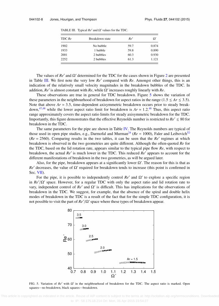
These observations are true in general for TDC breakdown. Figure 5 shows the variation ofthese parameters in the neighbourhood of breakdown for aspect ratios in the range (1.5 ≤ Ar ≤ 3.5).Note that above Ar ≃ 3.5, time-dependent axisymmetric breakdown occurs prior to steady break-down,47,48 while the lower aspect ratio limit for breakdown is Ar ≃ 1.2.48 Thus, this aspect ratiorange approximately covers the aspect ratio limits for steady axisymmetric breakdown for the TDC.Importantly, this figure demonstrates that the effective Reynolds number is restricted to Re′ . 80 forbreakdown in the TDC.
The same parameters for the pipe are shown in Table IV. The Reynolds numbers are typical ofthose used in open pipe studies, e.g., Darmofal and Murman24 (Re = 1000), Faler and Leibovich52
(Re = 2560). Comparing results in the two tables, it can be seen that the Re′ regimes at whichbreakdown is observed in the two geometries are quite different. Although the often-quoted Re forthe TDC, based on the lid rotation rate, appears similar to the typical pipe flow Re, with respect tobreakdown, the actual Re′ is much lower in the TDC. This reduced Re′ appears to account for thedifferent manifestations of breakdown in the two geometries, as will be argued later.
Also, for the pipe, breakdown appears at a significantly lower Ω′. The reason for this is that asRe′ decreases, the value of Ω′ required for breakdown tends to increase (this point is confirmed inSec. VII).
For the pipe, it is possible to independently control Re′ and Ω′ to explore a specific regionin Re′/Ω′ space. However, for a regular TDC with only the aspect ratio and lid rotation rate tovary, independent control of Re′ and Ω′ is difficult. This has implications for the observations ofbreakdown in the TDC. We suggest, for example, that the absence of the spiral and double helixmodes of breakdown in the TDC is a result of the fact that for the simple TDC configuration, it isnot possible to visit the part of Re′/Ω′ space where these types of breakdown appear.
FIG. 5. Variation of Re′ with Ω′ in the neighbourhood of breakdown for the TDC. The aspect ratio is marked. Opensquares—no breakdown, black squares—breakdown.
This article is copyrighted as indicated in the article. Reuse of AIP content is subject to the terms at: http://scitation.aip.org/termsconditions. Downloaded
to IP: 58.175.18.214 On: Mon, 06 Apr 2015 23:54:27
044102-9 Jones, Hourigan, and Thompson Phys. Fluids 27, 044102 (2015)
TABLE IV. Typical Re′ and Ω′ values for breakdown in the pipe of Falerand Leibovich.52
Pipe Re Ω Breakdown state Re′ Ω′
F&L 2560 1.0 Spiral 832 0.574F&L 1280 1.0 Spiral 416 0.588
VI. BREAKDOWN VARIATION BETWEEN GEOMETRIES AND THE CLASSIFICATIONOF BREAKDOWN
The vortex breakdown observed in open pipes and over delta wings has been characterised asa jump transition of the entire steady flow to another steady flow state.56 It is difficult to reconcilethe gradual transformation from parallel streamline flow to progressive streamline expansion andeventual development of a stagnation point and recirculation region in the TDC (Figure 2) with thispicture of breakdown.
However, in Sec. V, the very different Re′/Ω′ regimes normally occupied by the pipe andTDC flows were highlighted, and at sufficiently low Reynolds number, the gradual transition tobreakdown in the open pipe does resemble that observed in the TDC.
The difference in Re′/Ω′ regime also potentially provides an explanation for the absence of thespiral form of breakdown in the TDC. We propose that the reason for the lack of a (completely)axisymmetric bubble, and prevalence of the spiral form in the pipe, is the comparatively muchhigher Re′ at which pipe studies are conducted. The higher effective Reynolds number means thatviscous damping is lower, perhaps allowing spiral modes to be amplified. Experimentally, it wouldbe very difficult to obtain results in the pipe for the Re′ and Ω′ values that result in breakdown in theTDC. However, it is a relatively simple matter to investigate these flows numerically. This will beundertaken in Sec. VII.
VII. THREE-DIMENSIONAL SIMULATION OF THE PIPE FLOW
To test the hypothesis that the spiralling asymmetry in the pipe is due to the high Reynoldsnumbers normally used, we examine solutions for decreasing Reynolds number and observe whetherthe flow (with breakdown) subsequently becomes axisymmetric. As expected, decreasing Reynoldsnumber led to an increase in the amount of swirl necessary for breakdown.
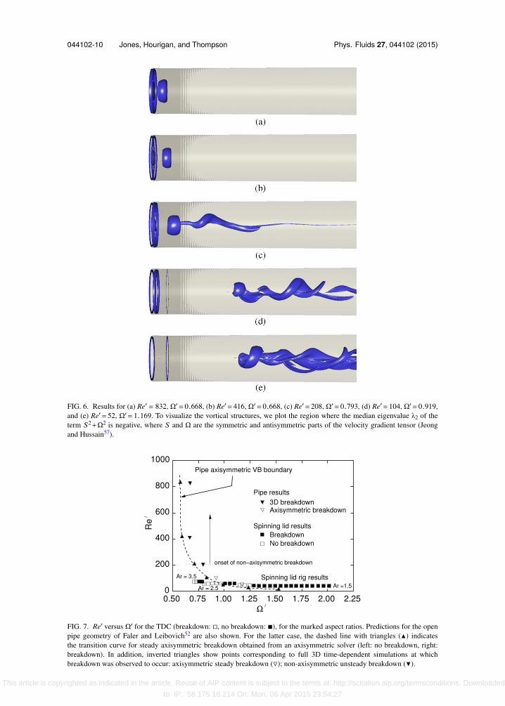
Some three-dimensional solutions are visualised in Figure 6.As Re′decreases, the three-dimensionality that is present from Re′ = 832 to Re′ = 208 completely
disappears by Re′ = 104. In addition, at Re′ = 104, the bubble resembles much more closely the typeof bubble observed in the TDC; the downstream end of the bubble has become closed. (This trendcan also be inferred from computations by Ruith et al.58 where, at constant swirl, increase in Refrom Re = 100 to Re = 300 resulted in a transition from axisymmetric bubble to spiral, then finallyto double helix breakdown.)
For Re′ = 104 and Re′ = 52, the bubble manifests very close to the inlet—compare this with theTDC, where breakdown also settles close to the upstream TDC wall. This type of breakdown wouldbe difficult to produce in the pipe experimentally because it would be difficult to constrain withinthe test section; in our case, the bubble is fixed by the inlet boundary condition. Hence, the absenceof the completely axisymmetric breakdown form (with no downstream spiral form) in open pipeexperiments is not unexpected.
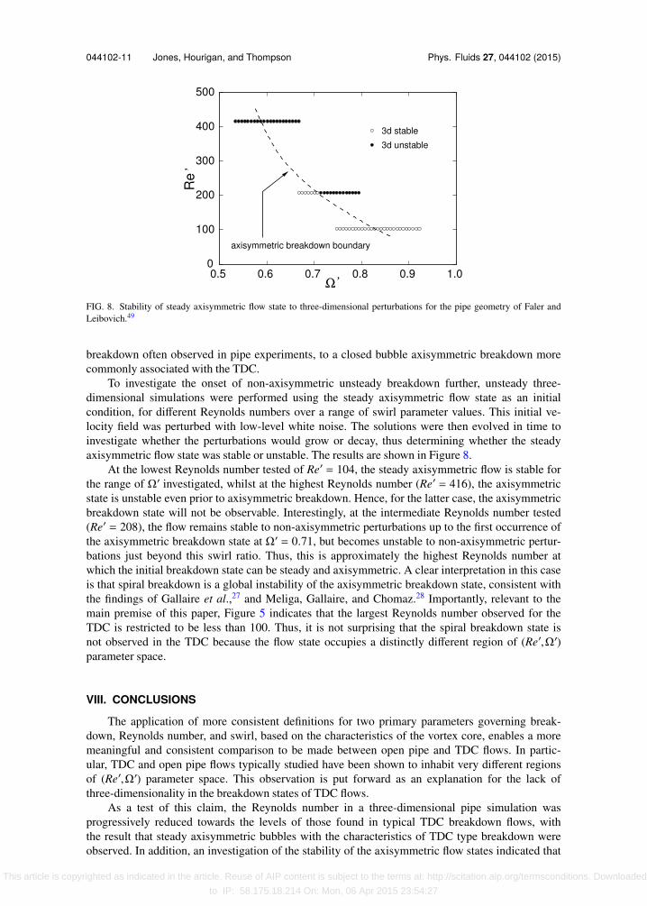
Re′ and Ω′ values for the three-dimensional pipe are plotted in Figure 7 along with values forthe TDC at various Reynolds numbers and aspect ratios. In addition, for the open pipe, the dottedline shows the transition from no breakdown (at low swirl) to breakdown (at high swirl), for steadyaxisymmetric breakdown. Those results are obtained from the steady axisymmetric solver.
It can be seen from this plot that with decreasing Re′ in the open pipe, the Ω′ required forbreakdown increases, until at the Re′where TDC breakdowns appear, the values of Ω′ nearly match.Hence, with decreasing Reynolds number, there is a gradual transition from the open spiral type
This article is copyrighted as indicated in the article. Reuse of AIP content is subject to the terms at: http://scitation.aip.org/termsconditions. Downloaded
to IP: 58.175.18.214 On: Mon, 06 Apr 2015 23:54:27
044102-10 Jones, Hourigan, and Thompson Phys. Fluids 27, 044102 (2015)
FIG. 6. Results for (a) Re′ = 832, Ω′= 0.668, (b) Re′= 416, Ω′= 0.668, (c) Re′= 208, Ω′= 0.793, (d) Re′= 104, Ω′= 0.919,and (e) Re′= 52, Ω′= 1.169. To visualize the vortical structures, we plot the region where the median eigenvalue λ2 of theterm S2+Ω2 is negative, where S and Ω are the symmetric and antisymmetric parts of the velocity gradient tensor (Jeongand Hussain57).
FIG. 7. Re′ versus Ω′ for the TDC (breakdown: , no breakdown: ), for the marked aspect ratios. Predictions for the openpipe geometry of Faler and Leibovich52 are also shown. For the latter case, the dashed line with triangles (N) indicatesthe transition curve for steady axisymmetric breakdown obtained from an axisymmetric solver (left: no breakdown, right:breakdown). In addition, inverted triangles show points corresponding to full 3D time-dependent simulations at whichbreakdown was observed to occur: axisymmetric steady breakdown (); non-axisymmetric unsteady breakdown ().
This article is copyrighted as indicated in the article. Reuse of AIP content is subject to the terms at: http://scitation.aip.org/termsconditions. Downloaded
to IP: 58.175.18.214 On: Mon, 06 Apr 2015 23:54:27
044102-11 Jones, Hourigan, and Thompson Phys. Fluids 27, 044102 (2015)
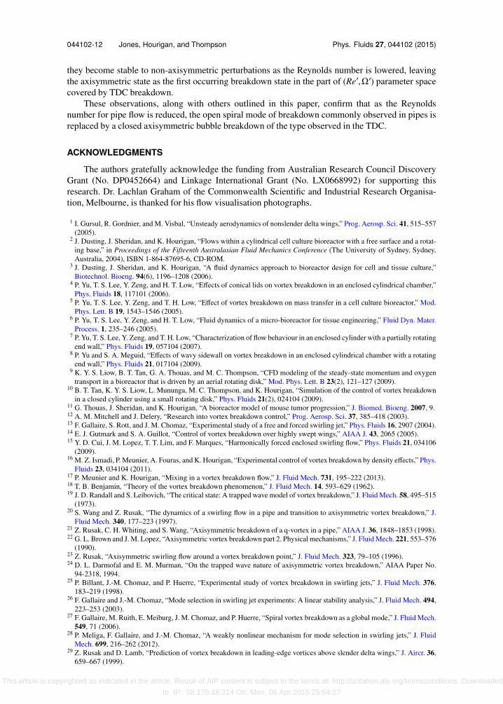
FIG. 8. Stability of steady axisymmetric flow state to three-dimensional perturbations for the pipe geometry of Faler andLeibovich.49
breakdown often observed in pipe experiments, to a closed bubble axisymmetric breakdown morecommonly associated with the TDC.
To investigate the onset of non-axisymmetric unsteady breakdown further, unsteady three-dimensional simulations were performed using the steady axisymmetric flow state as an initialcondition, for different Reynolds numbers over a range of swirl parameter values. This initial ve-locity field was perturbed with low-level white noise. The solutions were then evolved in time toinvestigate whether the perturbations would grow or decay, thus determining whether the steadyaxisymmetric flow state was stable or unstable. The results are shown in Figure 8.
At the lowest Reynolds number tested of Re′ = 104, the steady axisymmetric flow is stable forthe range of Ω′ investigated, whilst at the highest Reynolds number (Re′ = 416), the axisymmetricstate is unstable even prior to axisymmetric breakdown. Hence, for the latter case, the axisymmetricbreakdown state will not be observable. Interestingly, at the intermediate Reynolds number tested(Re′ = 208), the flow remains stable to non-axisymmetric perturbations up to the first occurrence ofthe axisymmetric breakdown state at Ω′ = 0.71, but becomes unstable to non-axisymmetric pertur-bations just beyond this swirl ratio. Thus, this is approximately the highest Reynolds number atwhich the initial breakdown state can be steady and axisymmetric. A clear interpretation in this caseis that spiral breakdown is a global instability of the axisymmetric breakdown state, consistent withthe findings of Gallaire et al.,27 and Meliga, Gallaire, and Chomaz.28 Importantly, relevant to themain premise of this paper, Figure 5 indicates that the largest Reynolds number observed for theTDC is restricted to be less than 100. Thus, it is not surprising that the spiral breakdown state isnot observed in the TDC because the flow state occupies a distinctly different region of (Re′,Ω′)parameter space.
VIII. CONCLUSIONS
The application of more consistent definitions for two primary parameters governing break-down, Reynolds number, and swirl, based on the characteristics of the vortex core, enables a moremeaningful and consistent comparison to be made between open pipe and TDC flows. In partic-ular, TDC and open pipe flows typically studied have been shown to inhabit very different regionsof (Re′,Ω′) parameter space. This observation is put forward as an explanation for the lack ofthree-dimensionality in the breakdown states of TDC flows.
As a test of this claim, the Reynolds number in a three-dimensional pipe simulation wasprogressively reduced towards the levels of those found in typical TDC breakdown flows, withthe result that steady axisymmetric bubbles with the characteristics of TDC type breakdown wereobserved. In addition, an investigation of the stability of the axisymmetric flow states indicated that
This article is copyrighted as indicated in the article. Reuse of AIP content is subject to the terms at: http://scitation.aip.org/termsconditions. Downloaded
to IP: 58.175.18.214 On: Mon, 06 Apr 2015 23:54:27
044102-12 Jones, Hourigan, and Thompson Phys. Fluids 27, 044102 (2015)
they become stable to non-axisymmetric perturbations as the Reynolds number is lowered, leavingthe axisymmetric state as the first occurring breakdown state in the part of (Re′,Ω′) parameter spacecovered by TDC breakdown.
These observations, along with others outlined in this paper, confirm that as the Reynoldsnumber for pipe flow is reduced, the open spiral mode of breakdown commonly observed in pipes isreplaced by a closed axisymmetric bubble breakdown of the type observed in the TDC.
ACKNOWLEDGMENTS
The authors gratefully acknowledge the funding from Australian Research Council DiscoveryGrant (No. DP0452664) and Linkage International Grant (No. LX0668992) for supporting thisresearch. Dr. Lachlan Graham of the Commonwealth Scientific and Industrial Research Organisa-tion, Melbourne, is thanked for his flow visualisation photographs.
1 I. Gursul, R. Gordnier, and M. Visbal, “Unsteady aerodynamics of nonslender delta wings,” Prog. Aerosp. Sci. 41, 515–557(2005).
2 J. Dusting, J. Sheridan, and K. Hourigan, “Flows within a cylindrical cell culture bioreactor with a free surface and a rotat-ing base,” in Proceedings of the Fifteenth Australasian Fluid Mechanics Conference (The University of Sydney, Sydney,Australia, 2004), ISBN 1-864-87695-6, CD-ROM.
3 J. Dusting, J. Sheridan, and K. Hourigan, “A fluid dynamics approach to bioreactor design for cell and tissue culture,”Biotechnol. Bioeng. 94(6), 1196–1208 (2006).
4 P. Yu, T. S. Lee, Y. Zeng, and H. T. Low, “Effects of conical lids on vortex breakdown in an enclosed cylindrical chamber,”Phys. Fluids 18, 117101 (2006).
5 P. Yu, T. S. Lee, Y. Zeng, and T. H. Low, “Effect of vortex breakdown on mass transfer in a cell culture bioreactor,” Mod.Phys. Lett. B 19, 1543–1546 (2005).
6 P. Yu, T. S. Lee, Y. Zeng, and H. T. Low, “Fluid dynamics of a micro-bioreactor for tissue engineering,” Fluid Dyn. Mater.Process. 1, 235–246 (2005).
7 P. Yu, T. S. Lee, Y. Zeng, and T. H. Low, “Characterization of flow behaviour in an enclosed cylinder with a partially rotatingend wall,” Phys. Fluids 19, 057104 (2007).
8 P. Yu and S. A. Meguid, “Effects of wavy sidewall on vortex breakdown in an enclosed cylindrical chamber with a rotatingend wall,” Phys. Fluids 21, 017104 (2009).
9 K. Y. S. Liow, B. T. Tan, G. A. Thouas, and M. C. Thompson, “CFD modeling of the steady-state momentum and oxygentransport in a bioreactor that is driven by an aerial rotating disk,” Mod. Phys. Lett. B 23(2), 121–127 (2009).
10 B. T. Tan, K. Y. S. Liow, L. Mununga, M. C. Thompson, and K. Hourigan, “Simulation of the control of vortex breakdownin a closed cylinder using a small rotating disk,” Phys. Fluids 21(2), 024104 (2009).
11 G. Thouas, J. Sheridan, and K. Hourigan, “A bioreactor model of mouse tumor progression,” J. Biomed. Bioeng. 2007, 9.12 A. M. Mitchell and J. Delery, “Research into vortex breakdown control,” Prog. Aerosp. Sci. 37, 385–418 (2003).13 F. Gallaire, S. Rott, and J. M. Chomaz, “Experimental study of a free and forced swirling jet,” Phys. Fluids 16, 2907 (2004).14 E. J. Gutmark and S. A. Guillot, “Control of vortex breakdown over highly swept wings,” AIAA J. 43, 2065 (2005).15 Y. D. Cui, J. M. Lopez, T. T. Lim, and F. Marques, “Harmonically forced enclosed swirling flow,” Phys. Fluids 21, 034106
(2009).16 M. Z. Ismadi, P. Meunier, A. Fouras, and K. Hourigan, “Experimental control of vortex breakdown by density effects,” Phys.
Fluids 23, 034104 (2011).17 P. Meunier and K. Hourigan, “Mixing in a vortex breakdown flow,” J. Fluid Mech. 731, 195–222 (2013).18 T. B. Benjamin, “Theory of the vortex breakdown phenomenon,” J. Fluid Mech. 14, 593–629 (1962).19 J. D. Randall and S. Leibovich, “The critical state: A trapped wave model of vortex breakdown,” J. Fluid Mech. 58, 495–515
(1973).20 S. Wang and Z. Rusak, “The dynamics of a swirling flow in a pipe and transition to axisymmetric vortex breakdown,” J.
Fluid Mech. 340, 177–223 (1997).21 Z. Rusak, C. H. Whiting, and S. Wang, “Axisymmetric breakdown of a q-vortex in a pipe,” AIAA J. 36, 1848–1853 (1998).22 G. L. Brown and J. M. Lopez, “Axisymmetric vortex breakdown part 2. Physical mechanisms,” J. Fluid Mech. 221, 553–576
(1990).23 Z. Rusak, “Axisymmetric swirling flow around a vortex breakdown point,” J. Fluid Mech. 323, 79–105 (1996).24 D. L. Darmofal and E. M. Murman, “On the trapped wave nature of axisymmetric vortex breakdown,” AIAA Paper No.
94-2318, 1994.25 P. Billant, J.-M. Chomaz, and P. Huerre, “Experimental study of vortex breakdown in swirling jets,” J. Fluid Mech. 376,
183–219 (1998).26 F. Gallaire and J.-M. Chomaz, “Mode selection in swirling jet experiments: A linear stability analysis,” J. Fluid Mech. 494,
223–253 (2003).27 F. Gallaire, M. Ruith, E. Meiburg, J. M. Chomaz, and P. Huerre, “Spiral vortex breakdown as a global mode,” J. Fluid Mech.
549, 71 (2006).28 P. Meliga, F. Gallaire, and J.-M. Chomaz, “A weakly nonlinear mechanism for mode selection in swirling jets,” J. Fluid
Mech. 699, 216–262 (2012).29 Z. Rusak and D. Lamb, “Prediction of vortex breakdown in leading-edge vortices above slender delta wings,” J. Aircr. 36,
659–667 (1999).
This article is copyrighted as indicated in the article. Reuse of AIP content is subject to the terms at: http://scitation.aip.org/termsconditions. Downloaded
to IP: 58.175.18.214 On: Mon, 06 Apr 2015 23:54:27
044102-13 Jones, Hourigan, and Thompson Phys. Fluids 27, 044102 (2015)
30 F. Renac and L. Jacquin, “Linear stability properties of lifting vortices over delta wings,” AIAA J. 45, 1942–1951 (2007).31 M. A. Herrada and R. Fernandez-Feria, “On the development of three-dimensional vortex breakdown in cylindrical regions,”
Phys. Fluids 18, 084105 (2006).32 M. C. Thompson and K. Hourigan, “The sensitivity of steady vortex breakdown bubbles in confined cylinder flows to rotating
lid misalignment,” J. Fluid Mech. 496, 129–138 (2003).33 M. Brøns, W. Z. Shen, J. N. Sørensen, and W. J. Zhu, “The influence of imperfections on the flow structure of steady vortex
breakdown bubbles,” J. Fluid Mech. 578, 453–466 (2007).34 K. Hourigan, L. W. Graham, and M. C. Thompson, “Spiral streaklines in pre-vortex breakdown regions of axisymmetric
swirling flows,” Phys. Fluids 7, 3126–3128 (1995).35 M. Brøns, M. C. Thompson, and K. Hourigan, “Dye visualization near a 3D stagnation point: Application to the vortex
breakdown bubble,” J. Fluid Mech. 622, 177–194 (2009).36 F. Marques and J. M. Lopez, “Precessing vortex breakdown mode in an enclosed cylinder flow,” Phys. Fluids 13, 1679–1682
(2001).37 J. M. Lopez, “Rotating and modulated rotating waves in transitions of an enclosed swirling flow,” J. Fluid Mech. 553,
323–346 (2006).38 J. N. Sørensen, V. Naumov, and V. L. Okulov, “Multiple helical modes of vortex breakdown,” J. Fluid Mech. 683, 430–441
(2011).39 J. M. Lopez, “Three-dimensional swirling flows in a tall cylinder driven by a rotating endwall,” Phys. Fluids 24, 014101
(2012).40 O. C. Zienkiewicz, The Finite Element Method, 3rd ed. (McGraw-Hill, London, 1977).41 M. C. Thompson, K. Hourigan, and J. Sheridan, “Three-dimensional instabilities in the wake of a circular cylinder,” Exp.
Therm. Fluid Sci. 12, 190–196 (1996).42 G. E. Karniadakis and G. Triantafyllou, “Three-dimensional dynamics and transition to turbulence in the wake of bluff
bodies,” J. Fluid Mech. 238, 1–30 (1992).43 M. C. Thompson, K. Hourigan, A. Cheung, and T. Leweke, “Hydrodynamics of a particle impact on a wall,” Appl. Math.
Model. 30, 1356–1369 (2006).44 M. D. Griffith, T. Leweke, M. C. Thompson, and K. Hourigan, “Pulsatile flow in stenotic geometries: Flow behaviour and
stability,” J. Fluid Mech. 622, 291–320 (2009).45 B. E. Stewart, M. C. Thompson, T. Leweke, and K. Hourigan, “Numerical and experimental studies of the rolling sphere
wake,” J. Fluid Mech. 643, 137–162 (2010).46 M. C. Thompson, T. Leweke, and M. Provansal, “Kinematics and dynamics of sphere wake transition,” J. Fluids Struct. 15,
575–586 (2001).47 J. M. Lopez, “Axisymmetric vortex breakdown part 1. Confined swirling flow,” J. Fluid Mech. 221, 533–552 (1990).48 M. P. Escudier, “Observations of the flow produced in a cylindrical container by a rotating endwall,” Exp. Fluids 2, 189–196
(1984).49 J. H. Faler and S. Leibovich, “Disrupted states of vortex flow and vortex breakdown,” Phys. Fluids 20, 1385–1400 (1977).50 T. Sarpkaya, “On stationary and travelling vortex breakdowns,” J. Fluid Mech. 45, 545–559 (1971).51 S. Leibovich, “Vortex stability and breakdown: Survey and extension,” AIAA J. 22, 1192–1206 (1984).52 J. H. Faler and S. Leibovich, “An experimental map of the internal structure of a vortex breakdown,” J. Fluid Mech. 86,
313–335 (1978).53 J. M. Delery, “Aspects of vortex breakdown,” Prog. Aerospace Sci. 30, 1–59 (1994).54 J. K. Harvey, “Some observations of the vortex breakdown phenomenon,” J. Fluid Mech. 14, 585–592 (1962).55 H. A. Vaidya, Ö. Ertunç, B. Genç, F. Beyer, Ç. Köksoy, and A. Delgado, “Numerical simulations of swirling pipe flows—
decay of swirl and occurrence of vortex structures,” J. Phys.: Conf. Ser. 318, 1–10 (2011).56 M. Goldshtik and F. Hussain, “Analysis of inviscid vortex breakdown in a semi-infinite pipe,” Fluid Dyn. Res. 23, 189–234
(1998).57 J. Jeong and F. Hussain, “On the identification of a vortex,” J. Fluid Mech. 285, 69–94 (1995).58 M. R. Ruith, P. Chen, E. Meiburg, and T. Maxworthy, “Three-dimensional vortex breakdown in swirling jets and wakes:
Direct numerical simulation,” J. Fluid Mech. 486, 331–378 (2003).
This article is copyrighted as indicated in the article. Reuse of AIP content is subject to the terms at: http://scitation.aip.org/termsconditions. Downloaded
to IP: 58.175.18.214 On: Mon, 06 Apr 2015 23:54:27