Embed Size (px)
Citation preview
A Study of Inclusions in Steel
Part I, ~ a t e r b ~ Segregation of Nonrnetallics in Steel Ingots
METALLOGRAPHIC methods provide the quickest and least expensive means for microscopic examination of nonmetallic inclusions in steel. Industry has used these methods for more than 30 years to determine the relative amounts of non- metallic~ present, either by counting and measuring the inclusions or by comparing the appearance of the steel under the nlicroscope with standard charts and photographs to which arbitrary ratings have been assigned. Considering thc very small area examined in cach test, such ratings are reasonably dependable and can be reproduced with surprising con- sistency. Inclusions can even be divided into general groups such as sulphides, silicates, and oxides.
To identify specific phases and tell mhcther they represcnt refractory matter, slag. or products of deoxidation is entirely another matter; and when the anlounts of dirt in the steel bccomc so grcat as to be critical, such identification can become a vital matter to both steelmaker and mctallographcr. Positive identification of the offending inclusion, especially with regard to its source, is thc first step Icad- ing to orderly elimination from heats _vet, to be made.
Chief difficulties in making positive identifications of nonnletallics by metallo- graphic methods sccm to be: (1) limita- tions in thc kinds of testing that may be used for inclusio~~s ~vhilc thcy remain embedded in steel; and (2) dependence of the metallographcr upon photographs
1
and \vritten descriptions, for the appear- ance of inclusions of known identity, to comparc with his samples undcr observation.
The present study was unclertakcn to aid in decreasing the time and cxpense required for positive identification of noninctallics in steel, by providing metal- lographic salnplcs with inclusions of known identity. Such samples could be kept for reference by a labcratory to compare with unknown inclusions in commercial steels, and for the training of mctallographers and technicians. Actual samples offer o~,~,ortunities for obscrva- tion and testing not otherwise available.
To providc the samplcs, a scries of 500- lb ingots was manufactured, containing inclusions developed either by deoxidation or by addition of extraneous nonnletallics such as slag and fireclay. The ingots werc melted and cast by a commercial foundry. Republic Stcel, where much of thc testing was carried out, rolled the bottom half of cach ingot, while the tops wcre retained in the as-cast state. This cnabled 01)- servers in both steel mills and foundries to examine samplcs in forms with which they were most familiar; and it pro- vided a study regarding the effects of a hot-working operation upon nonmetallic phases present.
JJThile the primary purpose of this project lies in thc idcntification of in- clusions, a nu~nbcr of significant details havc been rcvealcd during nlanufacturc and processing of the steel, which relate
06
Operating Metallurgy 107
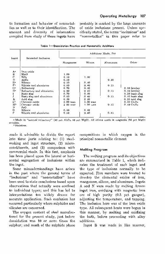
to formation and behavior of nonmctal- probably is maskcd by the largc amounts lics as \\rcll as to thcir identification. The of oxide inclusions present. Unless spe- amount and diversity of information cifically stated, the terms L'inclusions" and compiled from study of thesc ingots have "nonmetallics" in this paper refer to
Table 1-Deoxidation Practice and Nonmetallic Additions
Ingot
Iron oxide hlnO SiOz A1208 Silicate Silicate nnd aluminum Refractory Refractory and nlu~ninn~n Basic slag Basic slag and nl~llninnln Acid slug Chron~ic oxide Chronlic oxide FeO Silicate Silicatc and nluminuln
-
Intended Incl~lsion
0.10 fireclny 0.10 fireclay 0.10 basic slag 0.10 basic slag 0.10 acid slag 0.10 Crn01 0.10 Ct-203
- - - - - -
Additions Made, Pet
Manganese Silicon Aluminum Other
a Made in "nent,ral rcfrnctol.~" (40 pct A1103. 60 pct MgO). All others made in magnesia (98 yct MgO) cntcible.
Stainless.
made i t advisable to divide thc report into three parts rclating to: (1) steel- making and ingot structure, (2) micro- constituents, and (3) comparison with commercial steels. In this first, emphasis has been placcd upon the lateral or hori- zontal segregation of inclusions within the ingot.
Some misunderstandings have arisen in the past where the general terms of "inclusions" and "nonmetallics" havc been uscd to state conclusions bascd upon observations that actually wcre confined to individual types; and this has led to interpretations too widely drawn for accurate application. Such confusion has occurred particularly where sulphides and silicates are concerned.
The oxygen content of steel manufac- tured for the present study, just before deoxidation \vas 10 or more times thc sulphur; and much of thc sulphidc phasc
compositions in which oxygen is the principal nonmetallic element
Melting Program
The melting program and its objectives are summarized in Table 1, which indi- cates the treatment of each ingot and thc type of inclusions normally to be expected. Five members were treated to develop the elemental oxides of iron, manganese, silicon, and aluminum. Ingots A and N were made by melting Armco ingot iron, oxidizing with magnetic iron ore of high purity (0.5 pct gangue), adjusting the temperature, and tapping. The inclusion here was of the iron oxide type. All subsequent heats were begun in this manner, by melting and oxidizing the bath, before proceeding with alloy additions.
Ingot B was made in like manner,
108 Proceedings of Electric Furnace Conference, 1961
csccpt that 1 pct nlrtnganesc was added bout five minutcs beforc tap; whilc in ingot C, I pct silicon w3.s used. To ingot C a sm;tll amount (0. LO pct) of manganese
Table 2-Chemical Analysis of Production Materials PER CENT
was added to aid hot-workability: i t probably could have been omitted.
The only major breakdown in procedure took place with ingot D, where thc aluminum addition wcnt into the slag instead of the metal. No aluminum was recovered in the stecl, and the inclusions arc of the iron oxide typc. The ingot has been retained in this study for whatevcr valuc might dcvclop.
Ingots E through K, and 0 and P, wcrc deoxidized with mixtures of man- ganese and silicon about five minutes before tap. All these except K were made in pairs, one being treated mith aluminum 15 to 60 sec bcfore tap, the other remain- ing untreated. Some of these (El I?, 0, and P) were made to determine the kinds of inclusions formed through deosidation, and the effects of aluminum treatment upon them. Once the products of deoxi- dation had been established, powdered fireclay and furnace slag were added to other ingots madc by similar practice (ingots G, H, I, 5, K).
Thc last two ingots, L and M, were chromium stainless. Ingot M was treated with aluminum, L was not; to both, green
Con- stitu-
ent
c:hromium oxide (CrZOs) was atlcletl as tllcy wcrc cast into thc mold.
1\11 ingots were made from low-imp~l.ity gradcs of commercial materials: Armco
Low- *lectro- Irnpu-
lytic rity Nanga- 65 p ct
nese FeSi
Table 3-Chemical Analysis of Nonmetallic Additions PER CENT
I I I i
Armeo Ingot Iron
a Baker's C.P. grade.
SiOz AlrOa CaO MgO FeO
ingot iron, electrolytic manganese, and others. These, with typical analyses, are listed in Table 2.
The primary purpose of adding ex- traneous materials such as fireclay and slag was to obtain steel containing them or their alteration products as inclusions. Chemical compositions of the additions are givcn in Table 3. By carcful sizing of these nonmetallics, i t was hoped some insight into the validity of Stokes Law might be obtained either through dimen- sion frequency curves a t different levels in the ingot, or by determination of somc critical size above which the particles would not remain in the steel. Screen analyses are shown in Table 4, with fireclay and furnace slags ranging from +8 and +14 mesh to -325 mesh. Thc uniform fineness of chromium oxide was due to purchase of this chemical as a powder.
Three kinds of furnace refractories were used. Five ingots (Table 1) were made in a crucible of "neutral refractory" (60 pct MgO, 37 pct A1203) mith the pouring spout built up of an aluminum silicate con~position. The remaining 11 heats were made in magnesia (98 pct
Ferro- ehro- ~nii i rn
Grade
nulu Shot
61 .60 27.44 0 . 1 8 0 . 9 6
1 6 . 6 8 2 . 9 6
40 .99 10 .08 18.72
55 .20 7 . 5 2 7 . 1 7 0 . 5 9
1 0 . 2 2
Operating Metallurgy 109
MgO) with pouring spout also of mag- graphic samples of the as-cast metal. Addi- ~icsia. Compositions of these refractories tional slices were taken from the tops ad- are given in Table 5 . , jacent t o the surface already cut. These
To avoid the accidental introduction of were numbered consecutively, beginning
Toble 4-Screen Analysis of Nonmetallic Additions PER CENT
]:ireclay Basic O.H. Slag
Size, Mesh.
Acid E.1.'. Slag Chroniic Oxide
+ and - arc, respecti\.ely, larger than nnd smaller than the given mesh siac. b Fraction.
Cumulative.
ladle refractories, each ingot was cast di- with the first slice rcnloved fro111 thc mid- rcctly from the furnace into the iron mold. dle of the ingot as shown in Fig 1. For the same reason, the bottom of the Bottom halves each yielded 7 or 8 bars mold was closed by a cast-iron plug, and no l~rotective coating was applied t o the 1va11s.
The high degree of osidatio~i within the steel before alloys \$-ere added assured liberal amounts of inclusion-forming prod- ucts. To keep them in the metal, low tem- pcraturcs were maintained, especially a t tap, and the rate of freezing was acceler- ated by use of an ingot of long, narrow design. Where nonlnetallics were added, they were used in the mold. This provided steel not only saturated with inclusion- forming materials in solution but carry- ing in suspension large amounts of non- mctallics already precipitated, or added from the outside.
when rolled t o 1-in. diam. These were
Table 5-Chemical Analyses of Refractories" PER CENT
Magnesia Neutral A l n ~ n i n u i ~ ~ Refractory Refractory Silicate I 1
SiOl AlzOa CaO hlgO FexOs C r z 0 ~ Ti02
a Supl~licrs' typical analyses.
When the ingot was cold, i ts surface numbered corlsecutively, also beginning a t was examined, and the top dross or ingot the middle of thc ingot. Bars wcrc sam- scum was samplcd. Rclnoval of a cross- pled in 2-in. lcngths, split t o rcvcal the scctionsl etch slice a t the mid-point di- cross section. Mctallogral~hic samples of vided the ingot into top and bottom. After as-cast slices usually represented edge, bcing esamined and photographed, the midway, and center of a given ingot, each etch slice was used t o prepare metallo- piece slightly more than 1 in. long. Be-
110 Proceedings of Electric Furnace Conference, 1961
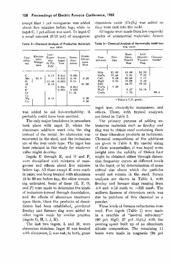
cause of the interest aroused in the edge after the slag had been removed, and sections, multiple san~ples were cut as 15 to 60 sec before tap. shown in Fig 1. Micrographs of rolled Temperatures werc measured by im- bars were cut longitudinally to expose the mersion thermocouple. Most tapping tem- entire cross section. peraturcs were around 2850°F, although
R O L L E D S E C T I O N A S - C A S T S E C T I O N
B A R NO. I
1 Fig 1-location of tests.
2
Melting and Casting Detail
5 1/4" 5
3 Z
All heats were made in the same 500-lb induction furnace and cast into the same iron ingot mold. Each heat was oxidized by 2 lb high-purity iron ore after melting was complete; and a few minutes were given for its digestion.
All alloys were added to the furnace. Where manganese and ferrosilicon were used in thc same heat, they werc mixed before being added. These two alloys mere given 5 minutes or more in thc fur- nace before tap. Aluminum was added
0 L m m. I
TESTS FROM INGOT SLICE
ingot F was recorded a t 2825" and ingot a t 2900".
Heats were lip-poured from the furnacc into the mold, which was suspcnded from an overhead crane. The mold was of com- mercial design used regularly in making tool steels. I ts ingot was 44 in. high by 7% in. square a t the top and 5% in. square a t the bottom, weighing 1180 lb. No hot top or mold wash was used. Ratio of mold weight to ingot was 2.36. At the beginning of each pour, thc cast-iron plug mas sealcd by a small amount of metal spilled from the furnace, arid then per-
Operating Metallurgy 11 1
~nit tcd to frccxc bcforc tlic rcm:rintlcr of thc ingot was C:LS~.
Powdcrcd fireclay, furnace sl:tgs, and chromium oxidc ncrc addcd to the mold in paper bags, each containing j/4 lb. One bag was drolq~ed into the mold imrnediatcly after thc plug had been sealed. When pouring had been rcsumecl and the metal being cast had riscn about 6 in. in the mold, a sccond bag as addcd, making a total of 35 lb, or 0.10 pct, based upon weight of thc ingot.
No covering was placed upon the tops of ingots. Timc for tops t o chill was 8 t o 20 sec. The ingots were stripped about 25 min. after completion of casting. They were placed upright in air to cool.
When stripped, the mold was cooled to about 200°F by running water and cleaned by brushing. When this was completed, thc nest heat was usually ready to tap.
Hot Working
After the surface had been examined, each ingot was divided into top and bot- tom sections, by removal of a cross-sec- tional etch slice a t the midway point. The bottom halves, 22 in. long by about 7 in. square a t thc upper end and 534 in. square a t the lower end, were not long enough to fit on the mill; so they were first heated to 2150°F and forged to 3%-in. square bars.
The bars were then rolled at 2200°F to 1-in. rounds. Each bottom yielded 7 or 8 bars, which were numbered consccutivcly beginning with the topmost. Saml~les of %in. lengths were cut from the bars, and these also were numbered consecutively beginning with the upper end.
Observations on Steelmaking
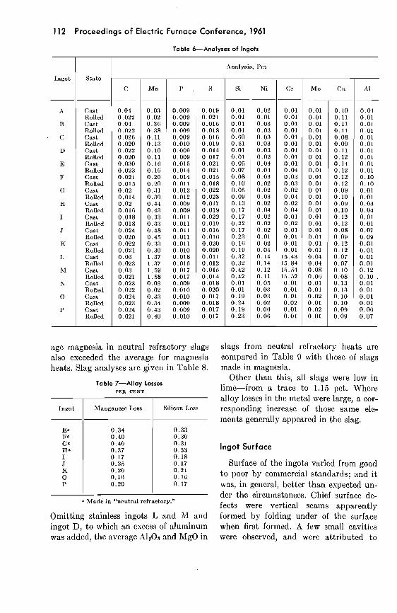
Analyses of both rolled and as-cast parts of each ingot are given in Table 6. Drillings from the cast section were taken midway between edge and center of cross- sectional slice No. 1. Bar No. 1, which
c:imc from mctal :itljncent t o this slicc in thc origin:~l ingot form, was drilled for :inalgsis of t l ~ c rolletl section. In calcu- lations of alloy losses (Tablc 7) and other data, analgscs of rolled scctions have been uscd.
Osygcn in the molten bath was not dutermined, but a high level of osidation was indicated by very low carbon and by substantial losses of manganese, silicon, and aluminum. Osggcn equivalents of thc total alloys lost from undivided heats rangcd from 0.211 pct to 0.565 pct.
Where mclting practice was compara- ble-for esample, in the heats deoxidized by 0.40 pct silicon and 0.40 to 0.80 pct manganese there was a striking differ- ence in Iosscs of alloys. Tablc 7 shows that heats E through H, made with "neutral refractory" lining and aluminum silicate pouring lip, sustained much heavier losses than heats made with thc magncsia lining and pouring lip. The average manganese loss for heats made with the composition lining was 0.38 pct against 0.20 pct for heats made in magnesia, while the average silicon losses were 0.32 pct and 0.18 pct, respectively.
I n drawing conclusions regarding chemi- cal relationships, it must be remembered that thc steel in this study was madc highly oxidized and low in temperature, and some of the circumstances wcre prone to prevent establishment of equilibrium conditions rather than promote thcm. While the alloy losses just given are fac- tual, they should by no means be used as the sole criteria in evaluating the worth of these refractories. For esamplc, such losses might become insignificant un- dcr circumstances where low-temperature bonding of the refractory would be all important.
Slags from the neutral refractory heats contained about twice as much alumina as slags from magnesia heats, 13.47 pct against 6.67 pct; and this probably is re- lated to thc higher losses of alloys. Avcr-
112 Proceedings of Electric Furnace Conference, 1961
Table 6-Analyses of Ingots
a Made in "neutml refractory."
Omitting stainless ingots L and M and ingot Dl to which an excess of aluminum was added, the average A1203 and MgO in
lngot
-
i\
13
C
D
E
F
C
H
I
J
K
L
R.1
N
0
P
age magnesia in neutral refractory slags also exceeded the average for magnesia heats. Slag analyses are given in Table 8.
Table 7-Alloy Losses PER CENT
slags from neutral refractory heats are compared in Table 9 with those of slags made in magnesia.
Other than this, all slags were low in lime-from a trace to 1.15 pct. Where alloy losses in the metal mere large, a cor- responding increase of those same ele- ments generally appeared in the slag.
State
Cast Rolled Cast Rolled Cnst Rolled Cnst Rolled Cnst Rolled Cast Rolled Cnst Rolled Cnst Rolled Cast Rolled Cast Rolled Cast Rolled Cast Rolled Cast Rolled Cnst Rolled Cnst Rolled Cast Rolled
Analysis, I'ct
Ingot Manganese Loss
lngot Surface
Silicon Loss
Surface of the ingots varied from good to poor by con~mercial standards; and i t was, in general, better than expected un- der the circumstances. Chief surface de- fects were vertical seams apparently formed by folding under of the surface when first formed. A few small cavities were observed, and were attributed to
C --
0.04 0.022 0.04 0.022 0.02G 0.020 0.022 0.020 0.030 0.023 0.021 0.015 0.02 0.014 0.02 0.016 0.018 0.018 0.024 0.020 0.022 0.021 0.03 0,023 0.08 0.021 0.023 0.022 0.024 0.023 0.024 0.021
P . 9 -
0.019 0.021 0.016 0.018 0.01G 0.019 0.014 0.017 0.021 0.021 0.015 0.018 0.022 0.023 0.017 0.019 0.022 0.019 0.01G 0.016 0.020 0.020 0.011 0.012 0.016 0.014 0.018 0.020 0.017 0.018 0.017 0.017
Mn
0.03 0.02 0.3G 0.38 0.11 0.13 0.10 0.11 0.1G 0.16 0.20 0.20 0.31 0.30 0.44 0.43 0.33 0.33 0.48 0.45 0.83 0.30 1.37 1.37 1.59 1.58 0.03 0.02 0.33 0.34 0.43 0.40
Si -
0.01 0.01 0.01 0.01 O.GO 0.61 0.01 0.01 0.05 0.07 0.08 0.10 0.0.5 0.09 0.13 0.17 0.17 0.22 0.17 0.23 O.l(i 0.19 0.32 0.32 0.42 0.42 0.01 0.01 0.19 0.24 0.19 0.23
-
0.009 0.009 0.009 0.009 0.009 0.010 0.009 0.009 0.015 0.014 0.014 0.011 0.012 0.012 0.009 0.009 0.011 0.011 0.011 0.011 0.011 0.010 0.018 0.016 0.017 0.017 0.009 0.010 0.010 0.009 0.009 0.010
Ni
-
0.02 0.01 0.03 0.03 0.03 0.03 0.03 0.02 0.04 0.04 0.03 0.02 0.02 0.03 0.02 0.04 0.02 0.02 0.02 0.01 0.02 0.04 0.14 0.14 0.12 0.11 0.05 0.03 0.08 0.02 0.06 0.06
Cr -
0.01 0.01 0.01 0.01 0.01 0.01 0.01 0.01 0.01 0.04 0.03 0.03 0.02 0.04 0.02 0.04 0.01 0.02 0.01 0.01 0.01 0.01 15.43 15.84 15.64 1.5.52 0.01 0.01 0.01 0.02 0.01 0.01
Mo
0.01 0.01 0.01 0.01 0.01 0.01 0.01 0.01 0.01 0.01 0.01 0.01 0.01 0.01 0.01 0.01 0.01 0.01 0.01 0.01 0.01 0.01 0.04 0.04 0.08 O.OG 0.01 0.01 0.02 0.01 0.02 0.01
Cu --
0.10 0.11 0.11 0.11 0.08 0.09 0.11 0.12 0.14 0.12 0.12 0.12 0.09 0.10 0.09 0.10 0.12 0.12 0.08 0.09 0.12 0.12 0.07 0.07 0.10 0.08 0.13 0.13 0.10 0.10 0.09 0.09
A1
-
0.01 0.01 0.01 0.01 0.01 0.01 0.01 0.01 0.01 0.01 0.10 0.10 0.01 0.01 0.03 0.04 0.01 0.01 0.07 0.09 0.01 0.01 0.01 0.01 0.12 0.10 . 0.01 0.01 0.01 0.01 0.06 0.07
Operating Metallurgy 113
lo\\. pouring temperatures. As production continued, effects of mold wear became noticeable, but were not serious. Some washing was observed around the plug hole, but no plug leaks developed.
Table 8-Slag Compositions
Composition. P c t
Ingot
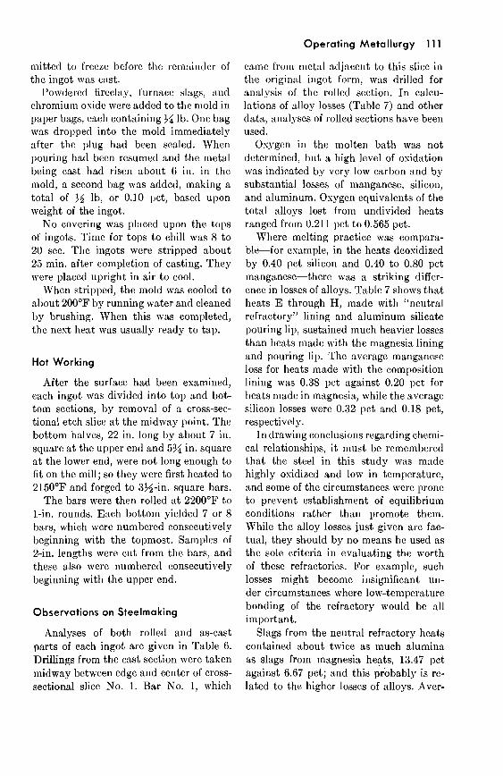
the addition had been completed with only 6 in. of metal in the mold. The nuin- ber of cases in which this occurred-all seven t h a t werc given mold additions- and the consistent pattern in the area
,Vhere nonmetallic materials had been Fig 2-Area covered by coatings of nonmetallic
additions. added t o a n ingot as i t was cast-ingots G, H, I, J, K, L and M-a part of this covcrcd seemed t o indicatc thc work of material appeared on thc vertical surfaces orderly forces, rather than accidental or
casual deposit of thesc residues. Table 9-Effects of Furnace Linings Upon Slags
PER CENT
mhcn the ingot was stripped. While such costings diffcrcd in dcnsity and did not account for any total addition, thcy were present on all four sides, and within about the samc area on all ingots. They began about 10 t o 12 in. from thc bottom and extended t o within 6 in. of the top, as sliown in Fig 2. The coatings adhered tightly and could not bc rctnoved easily from the surface.
The location of the coated area was of interest because i t began a t a height of 10 to 12 in, and extended upward, whereas
'I'yl~e Crucible
Neutral rcfractory.. . Magnesia.. . . . . . . . . .
Ingot Scum
Prcvious investigators1~3 have suggested tha t the dross or scum tha t collects on thc tops of ingots should indicate the compo- sition of inclusions remaining inside thc steel. This seems reasonable, sincc these slags have been described2 as, "consisting of deosidation products and eroded refrac- tory t h a t floats on the rising steel . . . ."
Only a few ingots in this s tudy bore a n y appreciable aniount of ingot scum or top dross, and in several cases i t was difficult t o collect enough for an analytical sample.
It mas espccted t h a t a t least the larger particles of noiii~~etallics addcd t o thc molds would join some deoxidation prod-
Heats
5 7
1 References are on page 127.
Avg MgO ---
13.49 11.41
Avg AlzOr
13.47 6.67
114 Proceedings of Electric Furnace Conference, 1961
ucts in forming the top dross on these ingots. The rate of ascent through liquid steel for a particle 1 mm in diameter is given in Basic Open Hearth Steelmaking3
Table 10-Ingot Scum
I Composition, Pct
SiOz A1208 CaO hlgO Mr10 FeO CrzOz l l l g Y t I I I ~
as 2 ft per sccond: the corresponding rate for a particle of 20-mcsh size would be 1.4 ft per second. Granted that the parti- cles actually prcsent would not be spheres, and that viscosity of the stcel would be on the high side, the 8 to 20 sec required for thc tops of thcse ingots to chill over should still have bcen more than enough time for them to rise the entire height of the ingot. Since the +20-mesh fractions amounted to about one half of thc addi- tions of fireclay mid basic open hearth slag, and 18 pct that of the acid slag, the amount of top dross from these sources alone should have been much greater than thc total amounts actually observed.
Ingot scum must be sampled carefully, since i t can vary greatly in composition and appearance a t locations only a few inches apart. Furthermore, in a lip-pour- ing operation, carc must be exercised to prevent furnacc slag from draining onto the casting after the stcel has been poured. In sampling, scale may be included inad-
vertently, or even mistaken for dross. The samples from A, B, C, D, and N were so high in iron oxide that i t is difficult to be certain they were entirely formed from an excess of oxide rejected by the metal.
Ingots G and H, to which fireclay had been added, contained hardly any top scum, in contrast t o the coatings found on the sides of these ingots. I t was difi- cult to gather the few grams requircd for chemical analysis. Ingots I, J, and K pos- sessed a little more scum than G and H, but the amounts were small in view of the nonmetallics adhering to their vertical sur- faces. The stainless ingots, which werc coated with the bright grcen chromium oxide Cr203, had a top dross of brown or tan.
Compositions of ingot scum are given in Table 10. The iron oxide of some of these has been mentioned: in five the FeO ex- ceeded 93 pct, while in the others i t ranged from 4 pct t o 82.4 pct.
All samples were low in CaO, from a trace to 1.17 pct. This was esl)ecially sig- nificant in I, J, and I<, t o which furnacc slags containing 40.99 pct and 7.17 pct CaO had been addcd. Lime contents of 0.66 pct, 0.50 pet, and 0.61 pet showed that little if any of thc slag addcd to the mold had risen to the tops and become incorporated into the ingot scum.
There was only a trace of MgO in scum samples very high in FeO (A, 13, C, D, and N) and in those from the stainlcss ingots (L and M). Tn scum from remain- ing ingots, the lowest was 5.38 pct and the highest 15.07 pct MgO; but no further pattern could be discenled. The only ma- terial actually addcd to the steel with a substantial MgO content mas basic open hearth slag with 10.08 pct, the acid elec- tric slag containing only 0.59 pct. Yet thc ingot scum from I, J (basic), and K (acid), to which these materials \Irere added, showed 7.70 pct, 6.11 pct, and 5.38 pct, respectively, indicating that little MgO, if any, came from the mold additions.
Operating Metallurgy 11 5
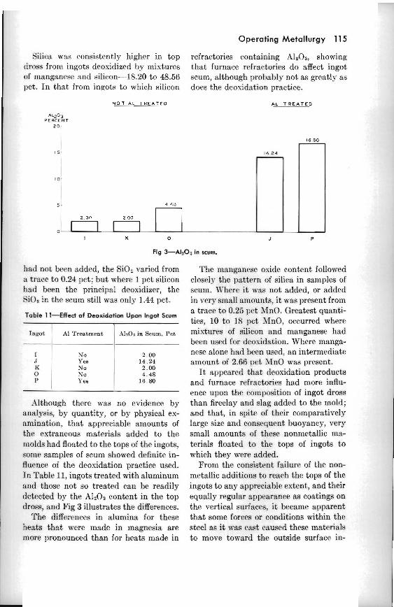
Silica was cor~sistcwtly higher in top refractories containing AI203, showing clross from ingots deoxidized by mixtures that furnace refractories do affect ingot of manganese and silicon-18.20 to 48.56 scum, although prohably not M greatly as pct. In that from ingots to which silicon does the dcosidation practice.
N O T A L T R E A T E D AL T R E A T E D
AL203 PERCENT
Fig +A1203 in scum.
had not been added, the Si02 varied from :I trace to 0.24 pct; but wherc 1 pct silicon had been the principal deosidizrr, the SiOz in the scum still was only 1.44 pct.
Table 11-Effect of Deoxidation Upon Ingot Scum
Inmt --
I .I I< 0 I'
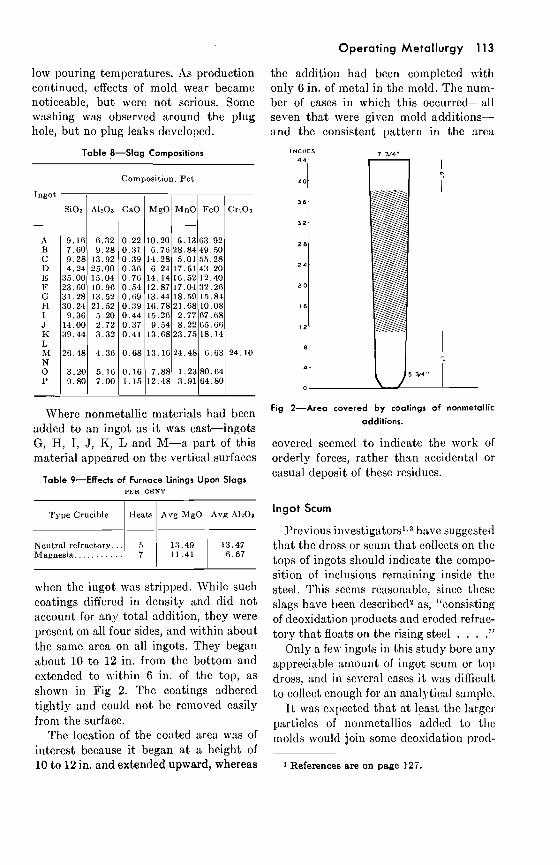
.L\lthough there was no evidence by ansIysis, by quantity, or by physical es- amination, that appreciable amounts of the extraneous materials added to the molds had floated to the tops of the ingots, some samples of scum showed definite in- fluence of the deosidation practice used. In Table 11, ingots treated with aluminum and those not so trented can he readily detected by the A1203 content in the top dross. and Fig 3 illustrates the differences.
The differrnces in alumina for these heats that were made in magnesia are more pronounced than for heats made in
A1 Treatment
No Yes No No Ye8
The manganese osidc content fo l lo~ed closely the pattern of silica in samples of scum. '\\'here it was not added, or added in very snlall an~ounts, it was present from a trace to 0.25 11ct AtnO. Greatest quanti- ties, 10 to I 8 pct NnO, occurred where mixtures of silicon and mnnganese had been used for dcouidation. \'herr manga- nese alone had bccn used, an internlediatr amount of 2.66 pr t >In0 was present.
It uppearcd that deosidation products and furnace refractories had more influ- ence upon the composition of ingot dross than fireclay and slag added to the mold; and that, in spite of their comparatively large size and consequent buoyancy, vcry small amounts of these nonmetallic ma- terials floated to the tops of ingots t~ which they were added.
From the consistent failure of the non- metallic additions to reach the tops of the ingots to any appreciable extent, and their equalIy regular nppearsnce as coatings on the vertical surfaces, i t became apparent that some forces or conditions within the steel as it was cant caused these materials to move toward the outside surface in-
AlsOr in Scum. Pet
2 . 0 0 1 4 . 2 1 2.00 4 . 4 8
16 81)
116 Proceedings of Electric Furnace Conference, 1961
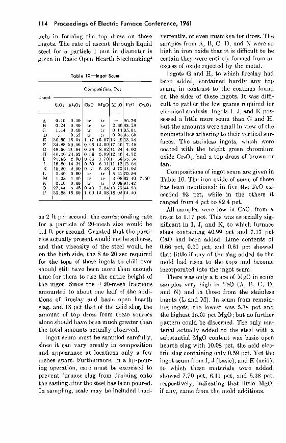
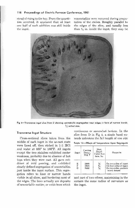
stead of rising to the top. From the quanti- nonmetallics were rcnloved during prcpa- ties ~nvolved, i t appeared that a.t Iemt ration of the etches. Roughly parallel to one half of each addition \\.as still inside the edges of the dice, and usually less the ingot. than % in. inside the ingot, they may be
Fig 4-Transverse ingot slice from D showing nonmetallic segregation near edges in form of narrow bands.
j/2 actual size.
Transverse Ingot Structure continuous or somewhat broken. In the slice from D in Fig 4, a single band es-
Cross-sectional slices taken from the tends unbroken the full length of one side of each ingot in the as-cast state Table 12-Effects of Temperature Upon Segregate
were faced off, then etched in 1:1 HC1 and water a t 160' to 180°F. All ingots except the two stainless exhibited center weakness, probably due to absence of hot tops when they were cast. All gave evi- dence of cold pouring, and exhibited clearly defined segregation of nonmetallics just inside the ingot surface. This sege- gation refers to lines or narrow bands visible in all slices, and bordering most of and part of two others, mtbintaining in the
Ingot
E F 0
the edges. The lines actually are deposits corners the same radius of curvature 3,s
of nonmetallic matter, or voids from which the ingot.
Remarks
On two sides of i n ~ o t On four sides of ingot On two sides, pockets
much deeper
Casting Temp., Deg
---
2900 2825 2850
Ma". Dept'h
Under Sur- face, In.
% 6 41
Operating Metallurgy 117
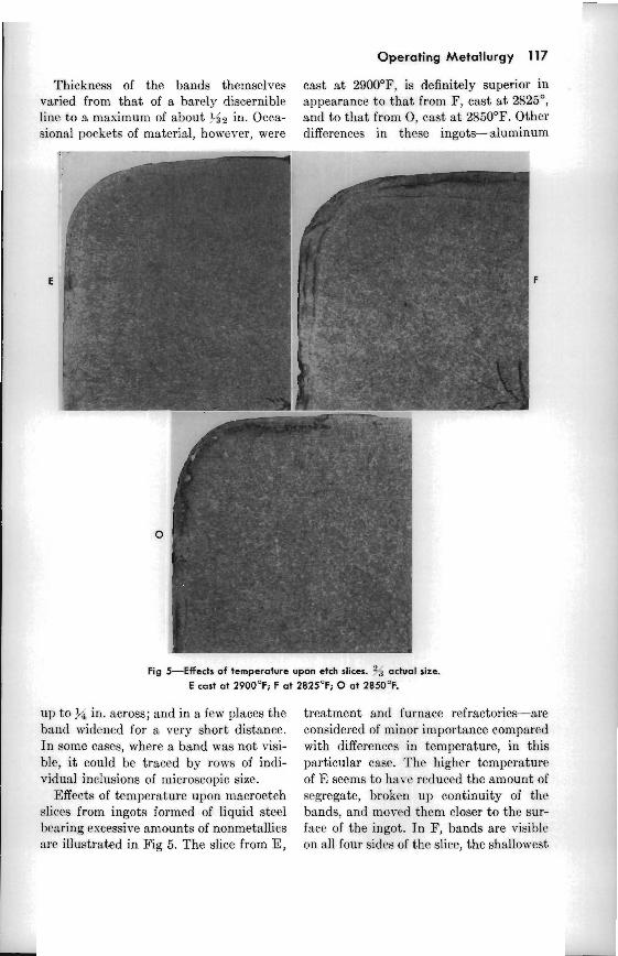
Thickness of the bands themselves cnst a t 2900°F, is definitely superior in varied from that of a barely discernible appearance to that from I?, cnst at 2825", line to a maximum of about 3$2 in. Occa- and to that from 0 , cast a t 2850°F. Other sionnl pockets of material, however, were differences in thcsc ingots-aluminum
Fig S E f f e d s of temperature upon etch slices. :"-i actual sire. E cast at 2900°F; F at 2825'F; 0 at 2850°F.
up to $i in. across; and in a few places the band widened for a very short distance. In some cases, where a band was not visi- ble, i t could be traced by rows of indi- vidual inclusions of microscopic size.
Effects of temperature upon macroctch slices from ingots formed of liquid steel bearing escessive amounts of nonmetallics :err illustrated in Fig 5. The slice from E,
treatment and furnace refractories-are considered of minor importance compared with differences in temperature, in this particular case. 'l'he higher temperature of E seems to hsv' reduced the amount of segregate, b r o k ~ n up continuity of the bands, and moved them closer to the sur- fnce of the ingot. In F, bands are visible on 311 four sides of the slice, the shallo\~cst
118 Proceedings of Electric Furnace Conference, 1961
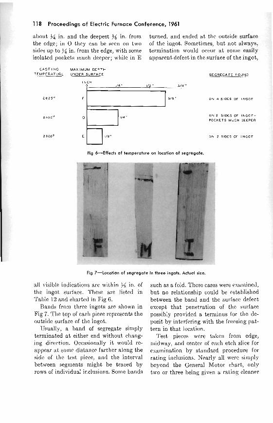
about in. and the deepest % in. from turned, and ended a t the outside surface the edge; in 0 they can be seen on two of the ingot. Sometimes, but not always, sides up to $/4 in. from the edge, with some termination would occur a t sonlo easily isolated pockets much deeper; while in E apparent defect in the surface of the ingot,
C A S T ING MAX IMUM DEPTH TEMPERATURE UNDER SURFACE Sf GREGATE FOUND
I N C H I " I ' , 3 4 '.
~ 8 2 5 ~ O N 4 SIDES OF I N G O T
O N 2 SIDES OF I N G O T -
POCKETS MUCH DEEPER
ON 2 SIDES OF I N G O T
Fig &Effects of temperature on location of segregate.
Fig 7-Location of segregate in three ingots. Actual size.
all visible indications are within M in. of the ingot surface. These are listed in Table 12 and charted in Fig 6.
Bands from three ingots are shown in Fig 7. The top of each piece represents the outside surface of the ingot.
Usually, a band of segregate simply terminated a t either end without chang- ing direction. Occasionrtlly i t would re- appear a t some distance farther along the side of the test piece, and the interval between segments might be traced by rows of individual inclusions. Some bands
such as a. fold. Thesc cases were examined, but no relationship could be established between the band and the surface defect except that penetration of the surface possibly provided a terminus for the de- posit by intrrfcring with the freezing pat- tern in that location.
Test pieces were taken from edge, midway, and center of each etch slice for examination by standard procedure for rating inclusions. Nearly all were simply beyond the General blotor chart, only two or three being given a rating cleaner
than 8. Edge samples containing the segre- gated zone were, of course, outstanding.
I n the chill zone, the ~nclusions were small and equiased; and they were well disperscd among grains of mctal. Between the nonmetallic bands or segregate and the center of the ingot, the inclusions again tended t o be of cqual axes, but size, dispersion, and actual shape varied greatly among the different ingots. Some had been formed by prec~pitat~ion; others, sltJhorigh suspended in the liquid steel, apparently had not been included in the segregation near the surface. Some small chromium inclusions in stainless occurred in rows on u line from edge to renter, probably be- tween columnar crystals. KO segregation mas so great as in the sl~bsurfare bands or curtain, although some treces could be ob- served in the secondnry pipe of one etch slice.
Further descr~ption of the individual inclusions will be taken up in part I1 of this study, t o be published later.
Composition of Segregate
The subsurfnce segregate was a hetero- geneous conglomeration of different non- metal l ic~ t h a t were suspendetl in the liquid steel-that is, deosidation products, bits of refractory, and particles of slag, and in some ingots, the nonmetallics tha t had hecn added to the mold. Most esami- nations thus far have been based upon samples from the first etch slices cut, those from the middle of each ingot.
Bssir and acid slags added t o the molds werc found in the segregate in different degees of alteration. Changes in particles of these oxidizing furnace slags added t o I, J , and K seemed t o follow a distinct pattern:
1. The FeO and a t least a par t of the X n O were reduced by sillcon and slumi- num contained in the steel.
2. Silica and aIumina formed in these I-cnctions were absorbed by the remainder
Operating Metallurgy 119
of the slag particle, rendering it more acid, and prohshly making the basic slags, a t least, more fluid.
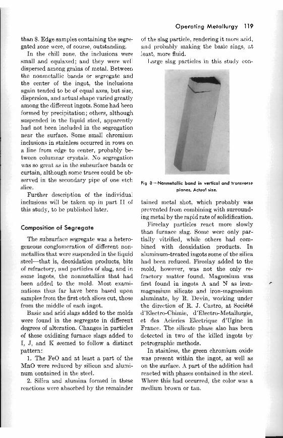
Lurge slag 1)~rticIes in this study con- - -
P.
Fig 8-Nonmetallic band in vertical and transverse
planes. Actual size.
tained mt.taI shot, which probably was prevented from combining with surround- ing metal by the rapid rate of solidification.
Fireclz~y particles react more slowly than furnace slae;. Some were only par- tially vitrified, while others had com- bined with deoxidstion products. I n aluminum-treated ingots some of the silira had b w n reduced. Fireclay added to the mold, however, was not the only re- fractory matter found. hIagnesium was first found in ingots A and N as iron- magnesium silicat,e anti iron-mngnesium aluminate, bj- H . Devin, working under the d i r ~ r t i o n of R. J . Castro, a t SociBtk dlElectro-Chimie, d'Electro-Metallurgir, e t des Acieries Electrique d'Ugine in France. The silicate phase also has been detected in two of the kiiled ingots by petrographic methods.
I n stainless, the green chromium ovide was present within the ingot, as well as on the surface. .I part of the addition had reacted with phases contained in the steel. \$-here this had occurred, the color was a medium brown or tan.
120 Proceedings of Electric Furnace Conference, 1961
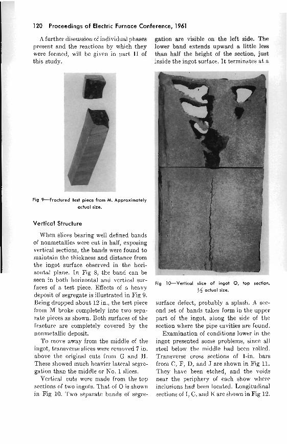
A further discussion of individual phases gation are visible on the left side. The present and the reactions by which they lower band extends upward a little less were formed, will be given in part I1 of than half the height of the section, just this study. inside the ingot surface. I t terminates a t a.
Fig 9-Fractured test piece from M. Approximately
actual size.
Vertical Structure
When slices bearing well defined bands of nonmetallics were cut in half, exposing vertical sections, the bands were found to maintain the thickness and distance from the ingot surface observed in the hori- zontal plane. In Fig S, the band can be - seen in both horizontal and vertical sur- faces of a test piece. Effects of a heavy deposit of segregate is illustrated in Fig 9. Being dropped about 12 in., the test piece from M broke completely into two sepa- rate pieces as shown. Both surfaces of the fracture are completely covered by the nonmetallic deposit.
To move away from the middle of the ingot, transverse slices were removed 7 in. above the original cuts from G and H. These showed much heavier lateral segre- gation than the middle or No. 1 slices.
Vertical cuts were made from the top sections of two ingots. That of 0 is shown in Fig 10. Two separate bands of segre-
Fig IWVer t ica l slice of ingot 0, top section.
J.i actual size.
surface defect, probably a splash. A sec- ond set of bands takes form in the upper part of the ingot, along the side of the section where the pipe cavities are found.
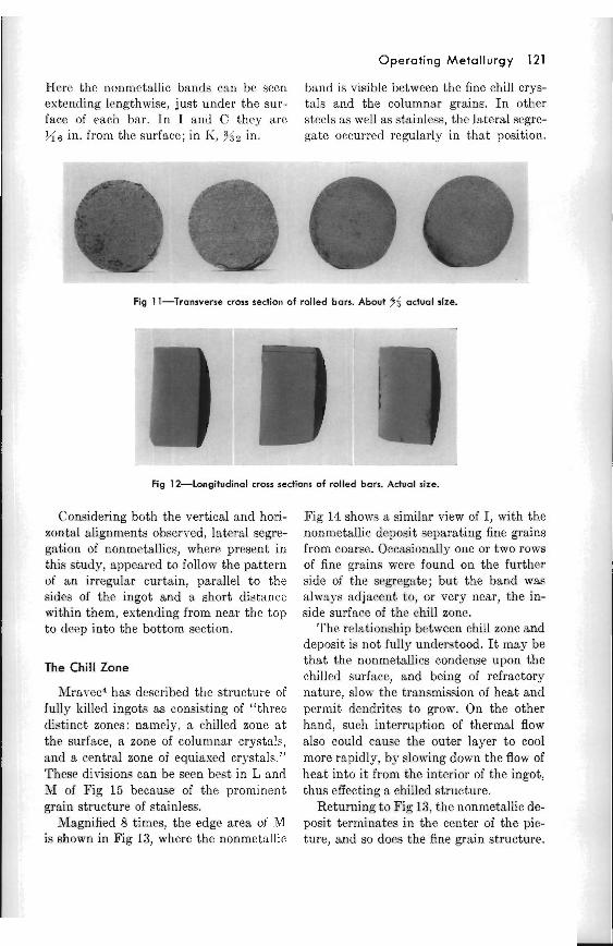
Examination of conditions lower in the ingot presented some problems, since all steel below the middle had been rolled. Transverse cross sections of 1-in. bars from C, F, D, and J are shown in Fig 11. They ha.ve been etched, and the voids near the periphery of each show whcrc i~lclusions had been located. Longitudinal sections of I, C, and K are shown in Fig 12.
Operating Metallurgy 121
H(src the nonn~ct:dlic bands c:in be scen band is visible between the fine chill crys- estending Itngthwise, just under the sur- tals and the columnar grains. I n other faco of each bar. In [ and C thry are stecls as well as stainless, the lateral segre- Ms in. from the surface; in I i , ? s z in. gate occurred regularly in that position.
Fig 11-Transverse cross section of rolled bars. About $5 actual size.
Fig 1 SLongitudinal cross sections of rolled bars. Actual size.
Considering both the vertical and hori- zontal alignments obscrvcd, lateral segre- gation of nonrnetallics, where present in this study, appeared to follow the pattern of an irregular curtain, parallel to the sides of the ingot and a short distance within them, extending from near the top to drep into the bottom section.
The Chill Zone
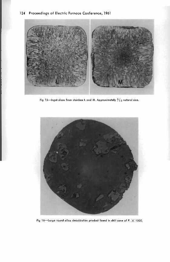
'i\Travec4 has described the structure of fully killed ingots as consisting of "three distinct zones: namrly, a chilled zone a t the surfme, a zone of colun~nar crystals, and a central zone of equiased crystals." These divisions can be seen best in L and M of Fig 15 because of the prominent grain structure of stainless.
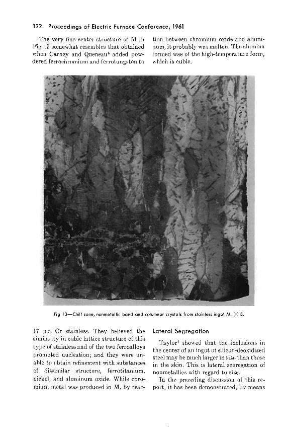
Magnified 8 times, the edge area of M is shown in Fig 13, where the nonmetallic
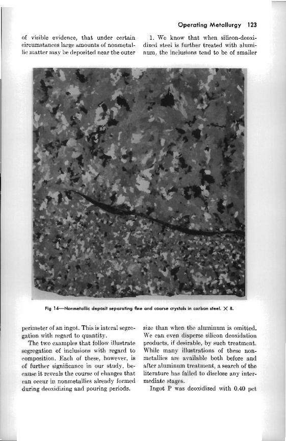
Fig 14 shows n similar view of I, with the nonmetallic deposit separating fine ga ins from coarse. Occasionally one or two rows of fine grains were found on the further side of the segregate; but the band was always adjacent to, or very near, the in- side surfarc of the chill zonc.
The relationship between chill zone and deposit is not fully understood. It may be that the nonmetdIics condense upon the chilled surface, and being of refractory nature, slow thc transmission of heat and permit dendrites to grow. On thc other hand, such interruption of thermal flow also could cause the outer layer to cool more rapidly, by slowing down the flow of heat into i t from the interior of the ingot, thus effecting a chilled structure.
Returning to Fig 13, the nonmetallic de- posit terminates in the center of the pic- ture, and so does the fine grain structure.
122 Proceedings of Electric Furnace Conference, 1961
The very fine center structure of M in tion between chromium oxide and alumi- Fig 15 somewhat resembles that obtained num, i t probably was molten. The alumina when Carney and Queneau6 added pow- formed was of the high-temperature form, dered ferrochromium and ferrotungsten to which is cubic.
Fig 13-Chill zone, nonmetallic band and columnar crystals from stainless ingot M. X 8.
17 pct Cr stainless. They believed the Lateral Segregation - -
similarity in cubic lattice structure of this Taylor0 showed that the inclusions in
of stainless and of the two ferroallO~s the center of an ingot of silicon-deoxidized promoted nucleation; and were "- steel may be larger in size than those able to obtain refinement with substances in the skin. hi^ is lateral segregation of of dissimilar structure, ferrotitanium, nonmetallics with regard to size. nickel, and aluminum oxide. While chro- I n the preceding discussion of this re- mium metal was produced in M, by reac- port, i t has been demonstrated, by means
Operating Metallurgy 123
of visible evidence, that under certain 1. We know that when silicon-deoxi- circumstances largc amounts of nonmetal- dized steel is further treated with alumi- lic matter may be deposited near the outer num, the inclusions tend to be of smaller
Fig 14-Nonmetallic deposit separating flne and coarse crystals in carbon steel. X 8.
perimeter of an ingot. This is lateral segre- gation ~ i t h regard to quantity.
The two examples that follo\v illustrate segregation of inclusions with regard to con~position. Each of these, however, is of further significance in our study, be- cause i t reveals the course of rhsnges that ran occur in nonmetallics already formed during deosidizing and pouring periods.
size than when the aluminunl is omitted. Ke can even disperse silicon deoxidation products, if desirable, by such trcstment. 14-hilc many illustrations of these non- n~etallics arc available both before and after aluminum trcatment, a search of the literature has failed to disclose any intcr- mediate stages.
Ingot P \~l.as deoxidized with 0.40 pct
124 Proceedings of Electric Furnace Conference, 1961
- - .
Fig I j l n g o t slices from stainless L and M. Approximately K2 natural size.
Fig 1 M a r g e round silica deoxidation product found in chill zone of P. X 1000.
Operating Metallurgy 125
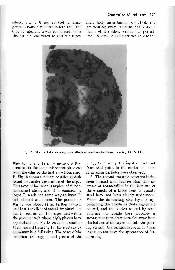
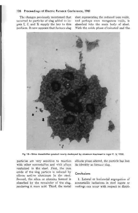
silicon and 0.60 pct electrolytic man- main body have become detached, and ganese about 5 n ~ ~ n u t e s before tap, and are floating away. i \ lun~ins has replsccstl 0.15 pct aluminum mas added just before much of t h r silica \\lt,hin the par t i ,~ l i~ the furnace, was tilted to cast the ingot. itself. Several of such particles p ere found
Fig 17-Silica inclusion showing some effects o f aluminum treatment, from ingot P. X 1000.
Figs 16, 17 and 18 show incalusions tlint oc*c,i~rrrd in the same micro test piece cut from the edge of the first slice from ingot P. Fig 16 shon-s a silicate or silica globule found just under the surface of the ingot. This type of inclusion is typical of silicon- deoxidized steels, and i t is common in ingot 0 , nlarle the same way as ingot P, hut without aluminum. The particle in Fig 17 was about >/4 in. further inward, and here the effect of a t tack by aluminum can be seen around the edges, and within the partirlr itself where .4l2O3 phases have crystallized out. Fig 18 was about another !$ in. in\vard from Fig 17. Here attack by aluminum is in full swing. The edges of the inc.lusion are ragged, and pieccs of the
about $6 In. under the ingot surface, but froln tha t point to the center, no morc large silica particles were observed.
2. Thc second example concerns inclu- sions formed from furnace slag. The in- crease of nonmetallirs in the last two or three ingots of n k~l lcd heat of quality steel have not been clearly understood. IYhile the descending slag layer is ap- proaching the nozzle as these ~ n g o t s are poured, and the vortcs caused by steel entcring the nozzle bore probably is strong enough to draw particles away from the bottom of the layer and into the pour- lng strcnm, the inclusions found in thcsc ingots d o not have the appearance of fur- nace slag.
126 Proceedings o f Electric Furnace Conference, 1961
The changes previously mentioned that shot representing the reduced iron oxide, occurred to particles of slag added to in- and perhaps even manganese oxide, is gots I, J, and K supply the key to this absorbed into the nlain body of steel. problem. I t now appears that furna,ce slag With the oxide phase eliminated and the
Fig 18-Silica deoxidation produd nearly destroyed by aluminum treatment in ingot P. X 1000.
particles are very sensitive to reaction silicate phase altered, the particle has lost with other nonmetallics and with alloys its identity as furtlacc slag. contained in the steel. First, the iron oxide of the slag particle is reduced by
Conclusions silicon and/or aluminum in the steel. Second, the silica or alumina formed is 1. Lateral or horizontal segregation of absorbed by the remainder of the slag, nonmetallic inclusions in steel ingots or rendering i t more acid. Third, the metal castings can occur with respect to distri-
Operating Metallurgy 127
bution of the quantities present and to different compositions present; as well as to size of particles, which was demon- strated by Taylor.
2. When steel containing appreciable amounts of nonmetallic matter is cast as an ingot, especially if the rate of solidifi- cation is rapid, the nonmetallics tend to segregate near the outer periphery of the casting in the form of curtain-like de- posits that are roughly parallel to the ingots' vertical surfaces.
3. Such segregation is converted into subsurface seams and stringers in prod- ucts rolled or forged from the ingot.
4. Increased casting temperatures re- duce the amount of lateral segregation and narrow the distance it occurs under the ingot surface.
5. The lateral displacement of non- metallic~ toward the outer perimeter of the ingot probably is caused by forces generated by the pouring stream; and it precedes any general movcment of inclu- sions caused by gravitation forces. This subsurface segregation takes place under different conditions and a t a different stage of ingot formation from the segre- gation a t the bottom center of the ingot, or thc flotation of individual particles.
6. The location of lateral segregation very near the surface, and its ap1~eamnce, probably have caused it to be coilfused in the past with defects due to pouring, such as splashes or scabs, "bootlegs" and \\,ash- ing caused by slanted nozzles, and to en- trapped ingot scum.
7. When a particle of open henrth slag or other slags high in iron oside are im- mcrsed in killed steel, the iron oside is reduced and the silica or alumina formed are absorbed by thc remainder of the particle.
8. Magnesium has been found in inclu- sions as an iron-magnesium silicate and as an aluininate or spinel.
9. When aluminum in steel reacts with large silica or silicate inclusions, the prod-
ucts of the reaction are of much smaller size.
10. In ingots that solidify rapidly, the top dross or scum may show greater influ- ence from deosidation practice and fur- nace refractories than from additions made to the molds.
11. Losses of manganese and silicon were greater for heats melted in a neutral refractory (60 pet illgo, 38 pct 1\120a) than for those made in very high magncsia (98 pct MgO).
Acknowledgments
This project was made possiblc by the generous aid of Republic Steel Corpo- ration, which rolled the steel and did most of the testing; and also supplied most of the illustrations shown in this report. The help of Vanadium Corporation of America also is gratefully acknowledged for its analyses of slags, ingot scum, and raw materials. The author is also indebted to R. J. Castro and the Soci6t6 d1Electro- Chimie for assistance.
References
1. l lai t , J . R. and H. W. Pindcr: Ol.igiri and Const~tutiorl of Certain Non-Metallic Inclusions in Steel. J . Iron n r ~ d Steel m s t . (1946) 4 , 371 K.
2. Forsyth, I-I. J., and L. G. Eckholm: Rlolds and l'ouring Practice. Basic Open Hearth Steelmaking, 428. A I M E , 1951.
3. Sims, C. E : Nonmetallic Inclusions. Basic Open Hearth Steelmaking, 459 ff. AIRIE, 1951.
4. h4ravec, J. G.: Control of Segregation and Ingot Stlwctures in Low Alloy Steels. Qual~ ty Rcquirements of Super-Duty Steels, 183. A I M E , 1958.
5. Carney, D. J.. and B. R. Queneau: Solidifi- cation of Stainless Steel Ingots. The Physical Chemistry of Steelmaking, 209 ff. &lass. Inst. of Tech. and John Wiley and Sons, 1959.
6. Taylor, C. R.: Sonre observations on the Metallurgy of Electric Furnace Melting. Elec. Fur. Steel Proc., A I M E (1950) 8, 96.
128 Proceedings of Electric Furnace Conference, 1961
Discussion G. G. ZIPF, DISCUSSION LEADER-htr.
Franklin has assumcd a tremendous job here in trying to cut down and simplify this thing in order to present it here today. An amazing amount of work was put into this article and, in all fairness to him, I think we should give him credit for the work that has been done.
Thc papcr, quitc frankly, is an attempt to simulate the most adverse conditions as far as stecl pouring is concerned; doing the rcvcrsc of what we all attempt to try to do in our shop, to keep the dirt and non- nletallics out, but to put them in there deliberately and attcmpt to try to deter- mine thc orientation and the position of thosc nonmctallics, forcign bodies in the
solidifying ingot. The paper gives idcas and thoughts as to places where we should be looking and things that we should bc doing. Most assuredly, we should strive to do everything possible to kcep out the undesirables.
B. H. BROWN, CHAIRMAN-For our next paper, me are indcbted to the Allegheny Ludlum Steel Corporation. I t is by hilr. S. Ramachandran, Research Metallurgist, Mr. R. A. Walsh, Research Rtctallurgist, and Mr. J. C. Fulton, Chief Research Nletallurgist, Allegheny Ludlum Steel Corporation. Mr. Fulton will present the paper.
Calculation of Oxygen Contents
in Molten Stainless Steels
FOR about thirty years continuous effort has been directed toward the appli- cation of physical chemistry to steel- making. While the benefits derived from numerous developments have been most rewarding, there continues to be a need for further progress in the use of thermo- dynamics to meet the more stringent rc- quircments for cleaner stcel. Rcsidual osygcn content is one of the most impor- tant factors that dctermine the inclusio~l content of stainless steels. For this reason, electric furnace practices have been devel- oped around this important consideration. Thus, the process may differ in the nature
of charge materials and source of osygcn for elimination of carbon, but it is uni- versal to have a finishing period a t the end of the heat cycle to deoxidize the bath. Although this featurc of elcctric furnace practice has long been in use, only in recent years has fundamental information been published coilccrning the ther~no- dynamics of alloying elerncnts that arc prcscnt in the finishing pcriod of the corn- moner staiillcss steels.
In order to understand the i~nl,ortunt factors in formation of ~lorln~ctallics in stainless steel, a long-range program was started a t Allegheny Ludlum Steel Corpo-