Embed Size (px)
Citation preview
International Research Journal of Applied and Basic Sciences © 2013 Available online at www.irjabs.com ISSN 2251-838X / Vol, 6 (2): 241-252 Science Explorer Publications
A study of CFRP composites effects in seismic retrofitting of concrete connections using ABAQUS
software
Ali Ghods1, Mahyar Mir2, Fahimeh Miri3
1,2,3. Azad university of Zahedan Branch, Civil Engineering faculty
Corresponding Author: Ali Ghods
ABSTRACT: It is for more than a decade that the category of improvement and quality enhancement of structural engineering infrastructures is considered as one of the most important issues. Devastation and annihilation of pillars, beams, connections and etc. are mainly attributed to aging of structure, harmful and destructive environmental factors, poor design or implementation of configurations, poor maintenance or incidents such as earthquakes. Meanwhile, using carbon-fibre-reinforced polymer composite materials (CFRP) as a practical solution is increasingly getting developed. Although formation of connections is one of the gravest factors affecting the behaviour of reinforced concrete, it is less paid attention and connections are usually brittle from this point. Thus, reinforcement of connections is a significant issue in civil engineering. In this article behaviour and deformation of applied beams in armed concrete which are reinforced with CFRP sheets is investigated. Designing procedure to determine the structures resistance is based on rigidity assessment of connection zone between carbon fibres and concrete. For this purpose the reinforced connection with CFRP sheets simulated by means of ABAQUS finite element software and an improvement in behaviour of the connection in terms of load capacity increase was observed. Keywords: Reinforcement and improvement, Carbon-fibre-reinforced polymer composite materials (CFRP), RC structures connections, Deflection of concrete beams, external reinforcement.
INTRODUCTION
It is known that most of RC structures in Iran and other parts of the world have lives of over several decades. Because of notability and abundance of these structures, it is not economically justified to replace them with new ones. Besides, it is an extremely time-consuming and practically impossible operation. Whereas, repairing and reinforcing of these buildings is usually an essential and affordable task. Therefore, observed weaknesses in infrastructures with demand to enhance and improve the quality have led to more complete and convincing requirements to be considered. At the same time, seismic retrofitting has become equally important. These days, various methods such as FRP
1 are used to repair and reinforce the RC structures.
Proper maintenance and safety of concrete structures under operation increases their efficiency. By recognition of cracks and deformations in structural components, sudden failure of the entire structure could be prevented. Thus, it is vital to reinforce significant infrastructures such as buildings and bridges which their number has grown due to expansion of cities and roads. Most of concrete buildings which are designed and built based on past regulations would show improper behaviours such as insufficient lateral resistance, poor dissipation of energy, rapid reduction of resistance and incorrect mechanisms to form plastic hinge. These improper behaviours may cause serious displacements and eventually destroy the building due to insufficient reinforcement detailing (fig.1).
1 - Fibre reinforced polymer
Intl. Res. J. Appl. Basic. Sci. Vol., 6 (2), 241-252, 2013
242
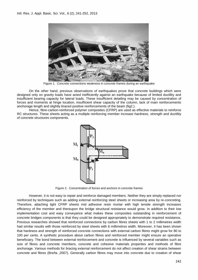
Figure 1. Concrete connections weakness in concrete frames during an earthquake
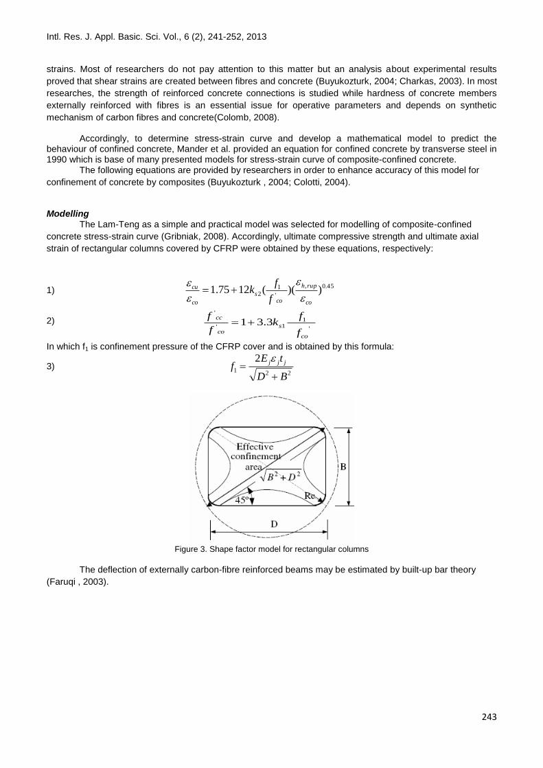
On the other hand, previous observations of earthquakes prove that concrete buildings which were designed only on gravity loads have acted inefficiently against an earthquake because of limited ductility and insufficient bearing capacity for lateral loads. These insufficient detailing may be caused by concentration of forces and moments at hinge location, insufficient shear capacity of the column, lack of main reinforcements anchorage length and slightly braced positive reinforcements of the beam (fig2.). Hence, fibre-carbon-reinforced polymer composites (CFRP) are used as effective materials to reinforce RC structures. These sheets acting as a multiple reinforcing member increase hardness, strength and ductility of concrete structures components.
Figure 2. Concentration of forces and anchors in concrete frames
However, it is not easy to repair and reinforce damaged members. Neither they are simply replaced nor
reinforced by techniques such as adding external reinforcing steel sheets or increasing area by re-concreting.
Therefore, attaching light CFRP sheets mid adhesive resin mortar with high tensile strength increases
efficiency of the member and thereupon the bridge structural resistance would grow. In addition to their low
implementation cost and easy conveyance what makes these composites outstanding in reinforcement of
concrete bridges components is that they could be designed appropriately to demonstrate required resistance.
Previous researches showed that reinforced connections by carbon fibres sheets with 1 to 2 millimetres width
had similar results with those reinforced by steel sheets with 6 millimetres width. Moreover, it has been shown
that hardness and strength of reinforced concrete connections with external carbon fibres might grow for 80 to
100 per cents. A synthetic procedure about carbon fibres and reinforced member might ensure an operative
beneficiary. The bond between external reinforcement and concrete is influenced by several variables such as
size of fibres and concrete members, concrete and cohesive materials properties and methods of fibre
anchorage. Various methods for bracing external reinforcement do not affect creation of shear strains between
concrete and fibres (Breña ,2007). Generally carbon fibres may move into concrete due to creation of shear
Intl. Res. J. Appl. Basic. Sci. Vol., 6 (2), 241-252, 2013
243
strains. Most of researchers do not pay attention to this matter but an analysis about experimental results
proved that shear strains are created between fibres and concrete (Buyukozturk, 2004; Charkas, 2003). In most
researches, the strength of reinforced concrete connections is studied while hardness of concrete members
externally reinforced with fibres is an essential issue for operative parameters and depends on synthetic
mechanism of carbon fibres and concrete(Colomb, 2008).
Accordingly, to determine stress-strain curve and develop a mathematical model to predict the behaviour of confined concrete, Mander et al. provided an equation for confined concrete by transverse steel in 1990 which is base of many presented models for stress-strain curve of composite-confined concrete. The following equations are provided by researchers in order to enhance accuracy of this model for
confinement of concrete by composites (Buyukozturk , 2004; Colotti, 2004).
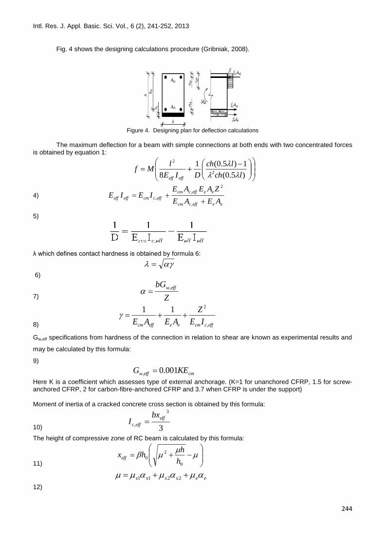
Modelling The Lam-Teng as a simple and practical model was selected for modelling of composite-confined
concrete stress-strain curve (Gribniak, 2008). Accordingly, ultimate compressive strength and ultimate axial
strain of rectangular columns covered by CFRP were obtained by these equations, respectively:
1) 45.0,
'
12 ))((1275.1
co
ruph
cos
co
cu
f
fk
2) '
11'
'
3.31
co
sco
cc
f
fk
f
f
In which f1 is confinement pressure of the CFRP cover and is obtained by this formula:
3) 221
2
BD
tEf
jjj
Figure 3. Shape factor model for rectangular columns
The deflection of externally carbon-fibre reinforced beams may be estimated by built-up bar theory
(Faruqi , 2003).
Intl. Res. J. Appl. Basic. Sci. Vol., 6 (2), 241-252, 2013
244
Fig. 4 shows the designing calculations procedure (Gribniak, 2008).
Figure 4. Designing plan for deflection calculations
The maximum deflection for a beam with simple connections at both ends with two concentrated forces is obtained by equation 1:
)5.0(
1)5.0(1
8 2
2
lch
lch
DIE
lMf
effeff
4)
eeeffccm
eeeffccm
effccmeffeffAEAE
ZAEAEIEIE
,
2
,
,
5)
λ which defines contact hardness is obtained by formula 6:
6)
7)
Z
bG effw,
8) effccmeeeffcm IE
Z
AEAE ,
211
Gw,eff specifications from hardness of the connection in relation to shear are known as experimental results and
may be calculated by this formula:
9)
cmeffw KEG 001.0,
Here K is a coefficient which assesses type of external anchorage. (K=1 for unanchored CFRP, 1.5 for screw-anchored CFRP, 2 for carbon-fibre-anchored CFRP and 3.7 when CFRP is under the support) Moment of inertia of a cracked concrete cross section is obtained by this formula:
10) 3
3
,
eff
effc
bxI
The height of compressive zone of RC beam is calculated by this formula:
11)
0
2
0h
hhxeff
12)
eessss 2211
Intl. Res. J. Appl. Basic. Sci. Vol., 6 (2), 241-252, 2013
245
13) eeesssss hahh 02220112
β factor may be calculated by this formula:
14) crcm
e
ME
ME04.0
It may be concluded from experimental data that deflection of RC beams which are reinforced with
carbon fibres are mainly influenced by shear deformation and appears in joint point of carbon fibres and
concrete. Therefore, analysing such structures requires evaluation of carbon fibres slip into concrete. Carbon
fibres were epoxied to RC beams in order to reinforce them. All of the beams and columns surfaces had been
already cleaned and degreased with metallic brushes (fig. 5).
Figure 5. Preparation of a bar surface for experiment
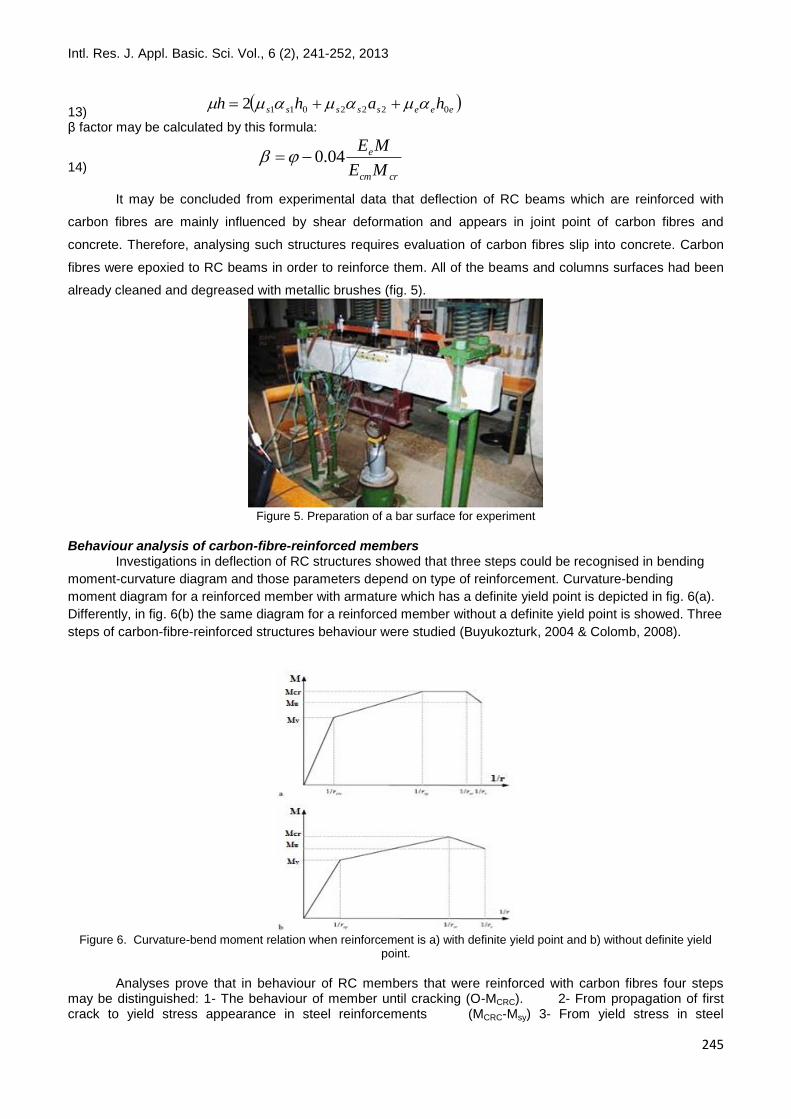
Behaviour analysis of carbon-fibre-reinforced members Investigations in deflection of RC structures showed that three steps could be recognised in bending
moment-curvature diagram and those parameters depend on type of reinforcement. Curvature-bending
moment diagram for a reinforced member with armature which has a definite yield point is depicted in fig. 6(a).
Differently, in fig. 6(b) the same diagram for a reinforced member without a definite yield point is showed. Three
steps of carbon-fibre-reinforced structures behaviour were studied (Buyukozturk, 2004 & Colomb, 2008).
Figure 6. Curvature-bend moment relation when reinforcement is a) with definite yield point and b) without definite yield
point.
Analyses prove that in behaviour of RC members that were reinforced with carbon fibres four steps may be distinguished: 1- The behaviour of member until cracking (O-MCRC). 2- From propagation of first crack to yield stress appearance in steel reinforcements (MCRC-Msy) 3- From yield stress in steel
Intl. Res. J. Appl. Basic. Sci. Vol., 6 (2), 241-252, 2013
246
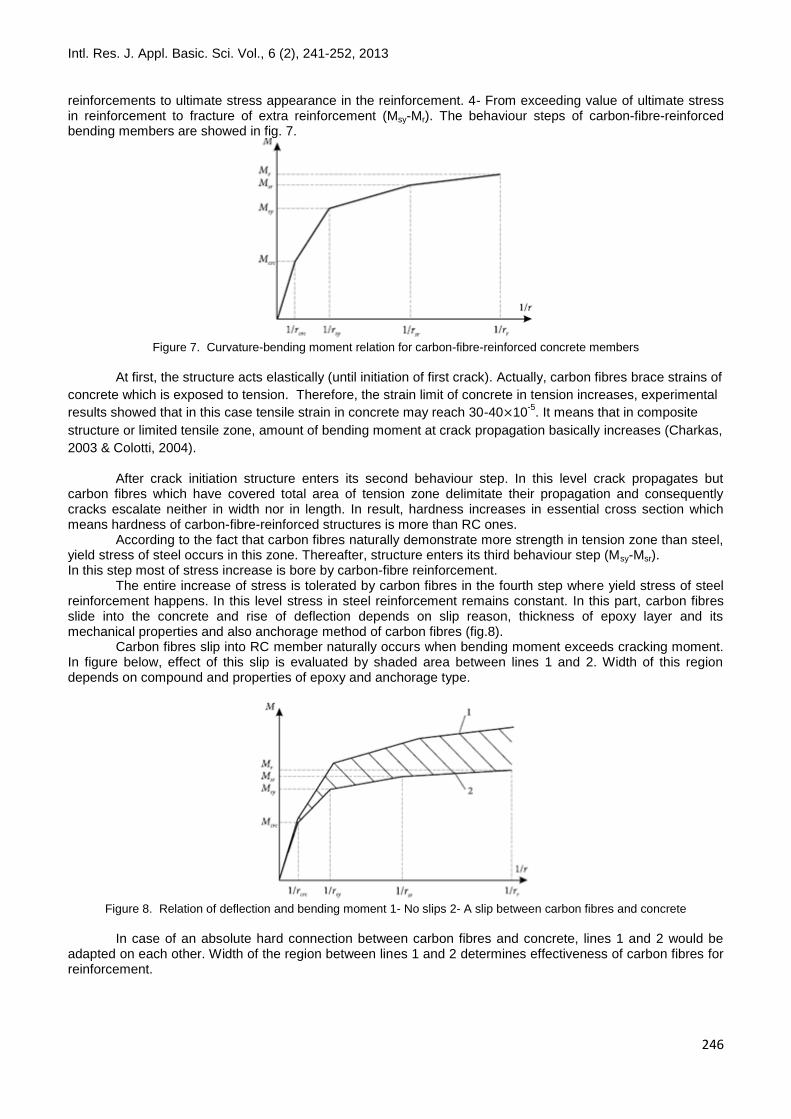
reinforcements to ultimate stress appearance in the reinforcement. 4- From exceeding value of ultimate stress in reinforcement to fracture of extra reinforcement (Msy-Mr). The behaviour steps of carbon-fibre-reinforced bending members are showed in fig. 7.
Figure 7. Curvature-bending moment relation for carbon-fibre-reinforced concrete members
At first, the structure acts elastically (until initiation of first crack). Actually, carbon fibres brace strains of
concrete which is exposed to tension. Therefore, the strain limit of concrete in tension increases, experimental
results showed that in this case tensile strain in concrete may reach 30-40 10-5
. It means that in composite
structure or limited tensile zone, amount of bending moment at crack propagation basically increases (Charkas,
2003 & Colotti, 2004).
After crack initiation structure enters its second behaviour step. In this level crack propagates but carbon fibres which have covered total area of tension zone delimitate their propagation and consequently cracks escalate neither in width nor in length. In result, hardness increases in essential cross section which means hardness of carbon-fibre-reinforced structures is more than RC ones. According to the fact that carbon fibres naturally demonstrate more strength in tension zone than steel, yield stress of steel occurs in this zone. Thereafter, structure enters its third behaviour step (Msy-Msr). In this step most of stress increase is bore by carbon-fibre reinforcement. The entire increase of stress is tolerated by carbon fibres in the fourth step where yield stress of steel reinforcement happens. In this level stress in steel reinforcement remains constant. In this part, carbon fibres slide into the concrete and rise of deflection depends on slip reason, thickness of epoxy layer and its mechanical properties and also anchorage method of carbon fibres (fig.8). Carbon fibres slip into RC member naturally occurs when bending moment exceeds cracking moment. In figure below, effect of this slip is evaluated by shaded area between lines 1 and 2. Width of this region depends on compound and properties of epoxy and anchorage type.
Figure 8. Relation of deflection and bending moment 1- No slips 2- A slip between carbon fibres and concrete
In case of an absolute hard connection between carbon fibres and concrete, lines 1 and 2 would be adapted on each other. Width of the region between lines 1 and 2 determines effectiveness of carbon fibres for reinforcement.
Intl. Res. J. Appl. Basic. Sci. Vol., 6 (2), 241-252, 2013
247
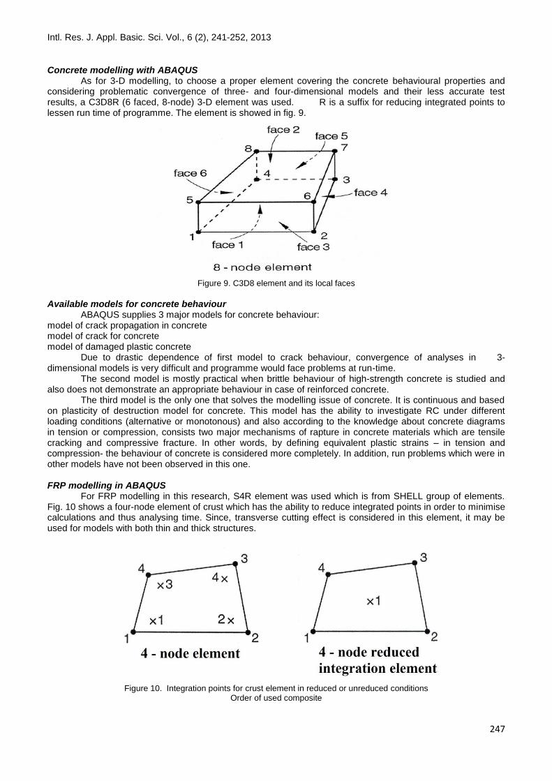
Concrete modelling with ABAQUS As for 3-D modelling, to choose a proper element covering the concrete behavioural properties and considering problematic convergence of three- and four-dimensional models and their less accurate test results, a C3D8R (6 faced, 8-node) 3-D element was used. R is a suffix for reducing integrated points to lessen run time of programme. The element is showed in fig. 9.
Figure 9. C3D8 element and its local faces
Available models for concrete behaviour ABAQUS supplies 3 major models for concrete behaviour: model of crack propagation in concrete model of crack for concrete model of damaged plastic concrete Due to drastic dependence of first model to crack behaviour, convergence of analyses in 3-dimensional models is very difficult and programme would face problems at run-time. The second model is mostly practical when brittle behaviour of high-strength concrete is studied and also does not demonstrate an appropriate behaviour in case of reinforced concrete. The third model is the only one that solves the modelling issue of concrete. It is continuous and based on plasticity of destruction model for concrete. This model has the ability to investigate RC under different loading conditions (alternative or monotonous) and also according to the knowledge about concrete diagrams in tension or compression, consists two major mechanisms of rapture in concrete materials which are tensile cracking and compressive fracture. In other words, by defining equivalent plastic strains – in tension and compression- the behaviour of concrete is considered more completely. In addition, run problems which were in other models have not been observed in this one. FRP modelling in ABAQUS For FRP modelling in this research, S4R element was used which is from SHELL group of elements. Fig. 10 shows a four-node element of crust which has the ability to reduce integrated points in order to minimise calculations and thus analysing time. Since, transverse cutting effect is considered in this element, it may be used for models with both thin and thick structures.
Figure 10. Integration points for crust element in reduced or unreduced conditions
Order of used composite
Intl. Res. J. Appl. Basic. Sci. Vol., 6 (2), 241-252, 2013
248
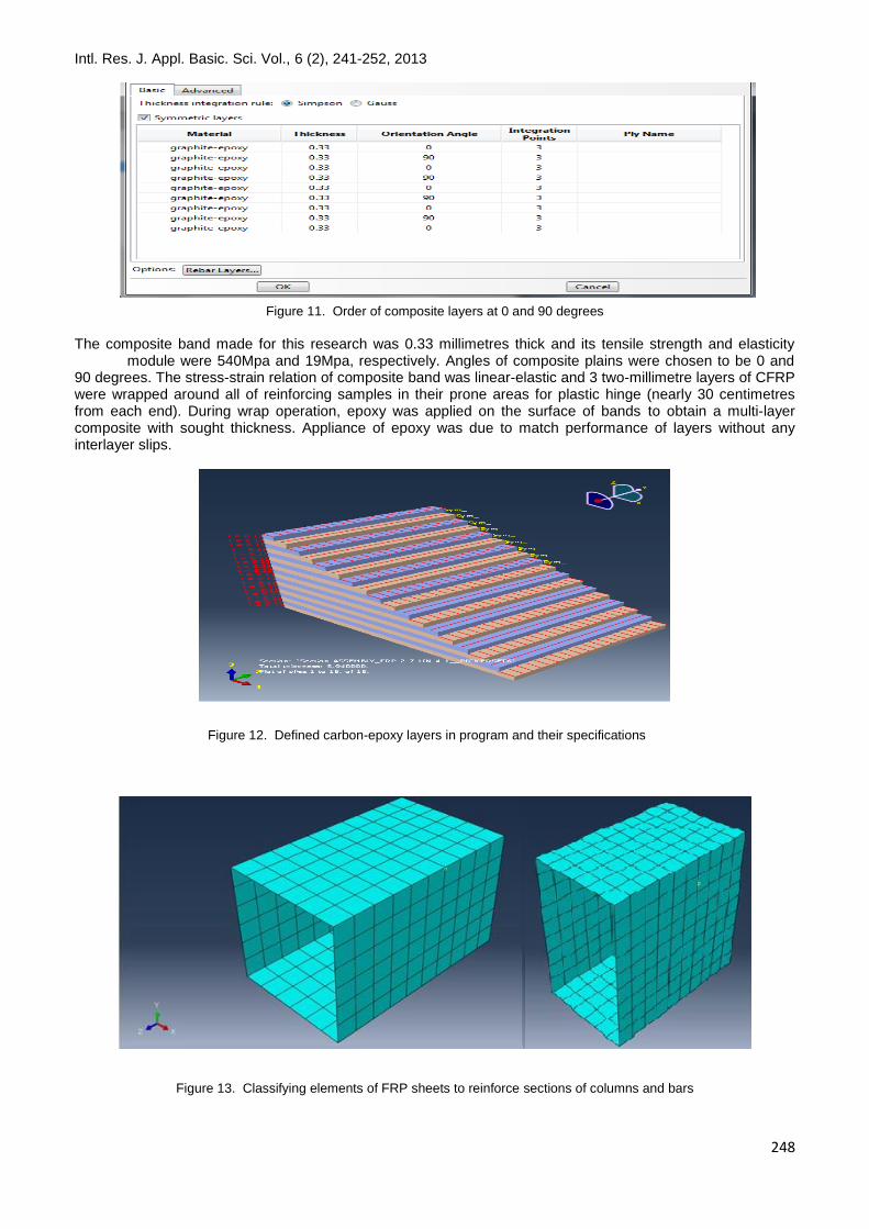
Figure 11. Order of composite layers at 0 and 90 degrees
The composite band made for this research was 0.33 millimetres thick and its tensile strength and elasticity module were 540Mpa and 19Mpa, respectively. Angles of composite plains were chosen to be 0 and 90 degrees. The stress-strain relation of composite band was linear-elastic and 3 two-millimetre layers of CFRP were wrapped around all of reinforcing samples in their prone areas for plastic hinge (nearly 30 centimetres from each end). During wrap operation, epoxy was applied on the surface of bands to obtain a multi-layer composite with sought thickness. Appliance of epoxy was due to match performance of layers without any interlayer slips.
Figure 13. Classifying elements of FRP sheets to reinforce sections of columns and bars
Figure 12. Defined carbon-epoxy layers in program and their specifications
Intl. Res. J. Appl. Basic. Sci. Vol., 6 (2), 241-252, 2013
249
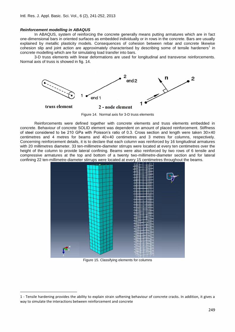
Reinforcement modelling in ABAQUS In ABAQUS, system of reinforcing the concrete generally means putting armatures which are in fact one-dimensional bars in oriented surfaces as embedded individually or in rows in the concrete. Bars are usually explained by metallic plasticity models. Consequences of cohesion between rebar and concrete likewise cohesion slip and joint action are approximately characterised by describing some of tensile hardeners
1 in
concrete modelling which are for simulating load transfer into bars. 3-D truss elements with linear deformations are used for longitudinal and transverse reinforcements. Normal axis of truss is showed in fig. 14.
Figure 14. Normal axis for 3-D truss elements
Reinforcements were defined together with concrete elements and truss elements embedded in concrete. Behaviour of concrete SOLID element was dependent on amount of placed reinforcement. Stiffness of steel considered to be 210 GPa with Poisson’s ratio of 0.3. Cross section and length were taken 30 40 centimetres and 4 metres for beams and 40 40 centimetres and 3 metres for columns, respectively. Concerning reinforcement details, it is to declare that each column was reinforced by 16 longitudinal armatures with 20 millimetres diameter. 33 ten-millimetre-diameter stirrups were located at every ten centimetres over the height of the column to provide lateral confining. Beams were also reinforced by two rows of 6 tensile and compressive armatures at the top and bottom of a twenty two-millimetre-diameter section and for lateral confining 22 ten-millimetre-diameter stirrups were located at every 15 centimetres throughout the beams.
Figure 15. Classifying elements for columns
1 - Tensile hardening provides the ability to explain strain softening behaviour of concrete cracks. In addition, it gives a way to simulate the interactions between reinforcement and concrete
Intl. Res. J. Appl. Basic. Sci. Vol., 6 (2), 241-252, 2013
250
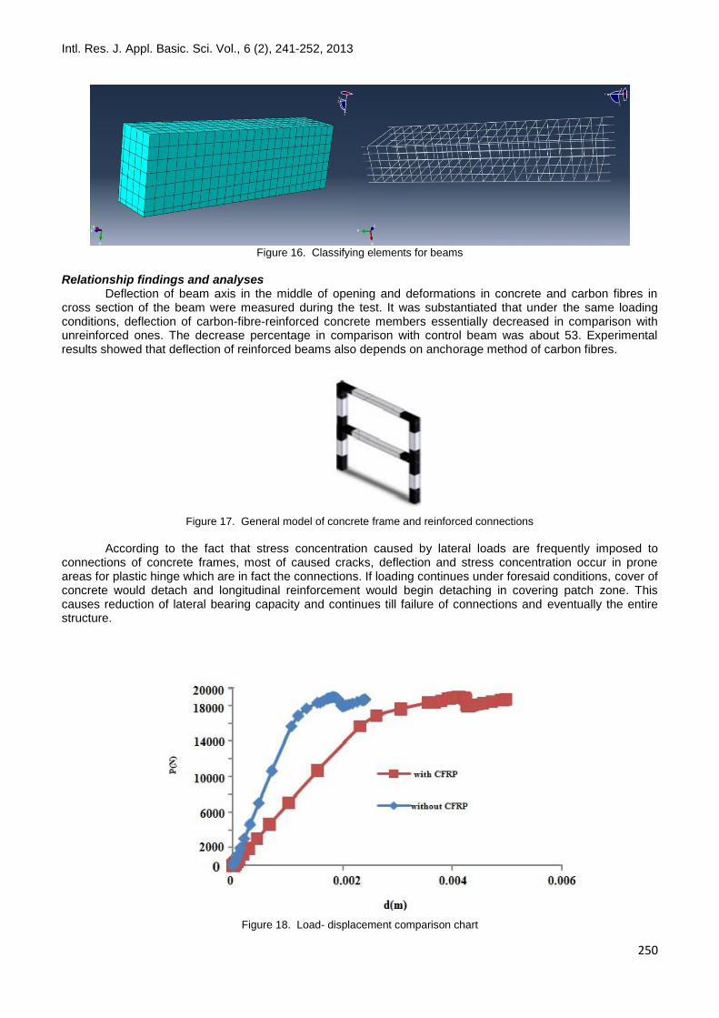
Figure 16. Classifying elements for beams
Relationship findings and analyses Deflection of beam axis in the middle of opening and deformations in concrete and carbon fibres in cross section of the beam were measured during the test. It was substantiated that under the same loading conditions, deflection of carbon-fibre-reinforced concrete members essentially decreased in comparison with unreinforced ones. The decrease percentage in comparison with control beam was about 53. Experimental results showed that deflection of reinforced beams also depends on anchorage method of carbon fibres.
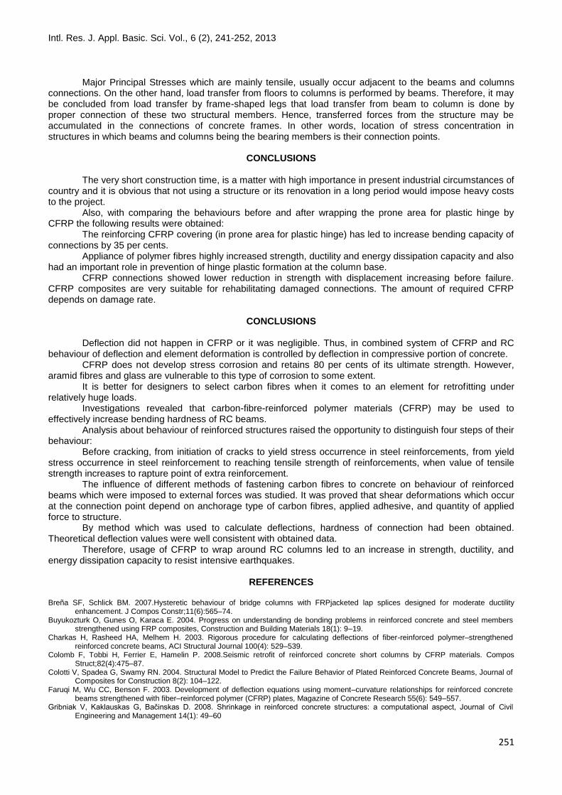
Figure 17. General model of concrete frame and reinforced connections
According to the fact that stress concentration caused by lateral loads are frequently imposed to connections of concrete frames, most of caused cracks, deflection and stress concentration occur in prone areas for plastic hinge which are in fact the connections. If loading continues under foresaid conditions, cover of concrete would detach and longitudinal reinforcement would begin detaching in covering patch zone. This causes reduction of lateral bearing capacity and continues till failure of connections and eventually the entire structure.
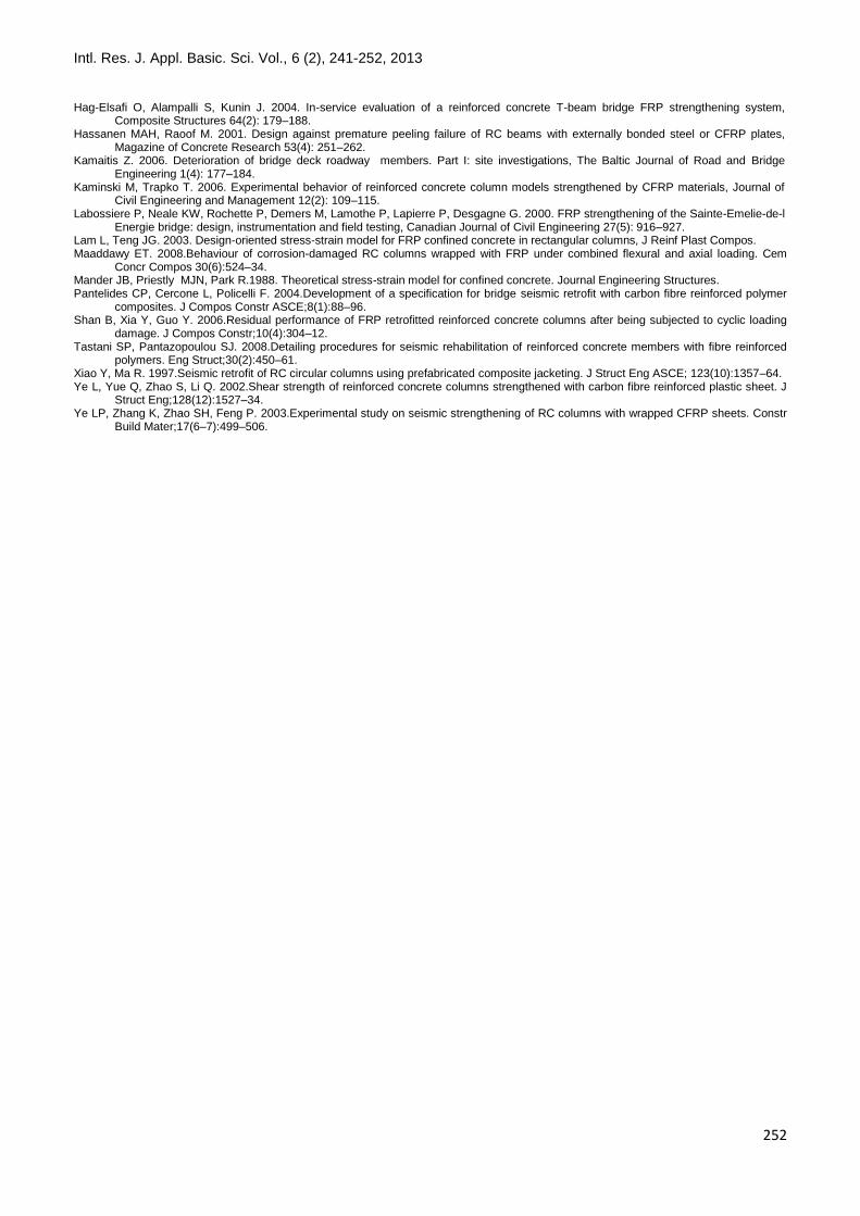
Figure 18. Load- displacement comparison chart
Intl. Res. J. Appl. Basic. Sci. Vol., 6 (2), 241-252, 2013
251
Major Principal Stresses which are mainly tensile, usually occur adjacent to the beams and columns connections. On the other hand, load transfer from floors to columns is performed by beams. Therefore, it may be concluded from load transfer by frame-shaped legs that load transfer from beam to column is done by proper connection of these two structural members. Hence, transferred forces from the structure may be accumulated in the connections of concrete frames. In other words, location of stress concentration in structures in which beams and columns being the bearing members is their connection points.
CONCLUSIONS The very short construction time, is a matter with high importance in present industrial circumstances of country and it is obvious that not using a structure or its renovation in a long period would impose heavy costs to the project. Also, with comparing the behaviours before and after wrapping the prone area for plastic hinge by CFRP the following results were obtained: The reinforcing CFRP covering (in prone area for plastic hinge) has led to increase bending capacity of connections by 35 per cents. Appliance of polymer fibres highly increased strength, ductility and energy dissipation capacity and also had an important role in prevention of hinge plastic formation at the column base. CFRP connections showed lower reduction in strength with displacement increasing before failure. CFRP composites are very suitable for rehabilitating damaged connections. The amount of required CFRP depends on damage rate.
CONCLUSIONS
Deflection did not happen in CFRP or it was negligible. Thus, in combined system of CFRP and RC behaviour of deflection and element deformation is controlled by deflection in compressive portion of concrete. CFRP does not develop stress corrosion and retains 80 per cents of its ultimate strength. However, aramid fibres and glass are vulnerable to this type of corrosion to some extent. It is better for designers to select carbon fibres when it comes to an element for retrofitting under relatively huge loads. Investigations revealed that carbon-fibre-reinforced polymer materials (CFRP) may be used to effectively increase bending hardness of RC beams. Analysis about behaviour of reinforced structures raised the opportunity to distinguish four steps of their behaviour: Before cracking, from initiation of cracks to yield stress occurrence in steel reinforcements, from yield stress occurrence in steel reinforcement to reaching tensile strength of reinforcements, when value of tensile strength increases to rapture point of extra reinforcement. The influence of different methods of fastening carbon fibres to concrete on behaviour of reinforced beams which were imposed to external forces was studied. It was proved that shear deformations which occur at the connection point depend on anchorage type of carbon fibres, applied adhesive, and quantity of applied force to structure. By method which was used to calculate deflections, hardness of connection had been obtained. Theoretical deflection values were well consistent with obtained data. Therefore, usage of CFRP to wrap around RC columns led to an increase in strength, ductility, and energy dissipation capacity to resist intensive earthquakes.
REFERENCES Breña SF, Schlick BM. 2007.Hysteretic behaviour of bridge columns with FRPjacketed lap splices designed for moderate ductility
enhancement. J Compos Constr;11(6):565–74. Buyukozturk O, Gunes O, Karaca E. 2004. Progress on understanding de bonding problems in reinforced concrete and steel members
strengthened using FRP composites, Construction and Building Materials 18(1): 9–19. Charkas H, Rasheed HA, Melhem H. 2003. Rigorous procedure for calculating deflections of fiber-reinforced polymer–strengthened
reinforced concrete beams, ACI Structural Journal 100(4): 529–539. Colomb F, Tobbi H, Ferrier E, Hamelin P. 2008.Seismic retrofit of reinforced concrete short columns by CFRP materials. Compos
Struct;82(4):475–87. Colotti V, Spadea G, Swamy RN. 2004. Structural Model to Predict the Failure Behavior of Plated Reinforced Concrete Beams, Journal of
Composites for Construction 8(2): 104–122. Faruqi M, Wu CC, Benson F. 2003. Development of deflection equations using moment–curvature relationships for reinforced concrete
beams strengthened with fiber–reinforced polymer (CFRP) plates, Magazine of Concrete Research 55(6): 549–557. Gribniak V, Kaklauskas G, Bačinskas D. 2008. Shrinkage in reinforced concrete structures: a computational aspect, Journal of Civil
Engineering and Management 14(1): 49–60
Intl. Res. J. Appl. Basic. Sci. Vol., 6 (2), 241-252, 2013
252
Hag-Elsafi O, Alampalli S, Kunin J. 2004. In-service evaluation of a reinforced concrete T-beam bridge FRP strengthening system, Composite Structures 64(2): 179–188.
Hassanen MAH, Raoof M. 2001. Design against premature peeling failure of RC beams with externally bonded steel or CFRP plates, Magazine of Concrete Research 53(4): 251–262.
Kamaitis Z. 2006. Deterioration of bridge deck roadway members. Part I: site investigations, The Baltic Journal of Road and Bridge Engineering 1(4): 177–184.
Kaminski M, Trapko T. 2006. Experimental behavior of reinforced concrete column models strengthened by CFRP materials, Journal of Civil Engineering and Management 12(2): 109–115.
Labossiere P, Neale KW, Rochette P, Demers M, Lamothe P, Lapierre P, Desgagne G. 2000. FRP strengthening of the Sainte-Emelie-de-l Energie bridge: design, instrumentation and field testing, Canadian Journal of Civil Engineering 27(5): 916–927.
Lam L, Teng JG. 2003. Design-oriented stress-strain model for FRP confined concrete in rectangular columns, J Reinf Plast Compos. Maaddawy ET. 2008.Behaviour of corrosion-damaged RC columns wrapped with FRP under combined flexural and axial loading. Cem
Concr Compos 30(6):524–34. Mander JB, Priestly MJN, Park R.1988. Theoretical stress-strain model for confined concrete. Journal Engineering Structures. Pantelides CP, Cercone L, Policelli F. 2004.Development of a specification for bridge seismic retrofit with carbon fibre reinforced polymer
composites. J Compos Constr ASCE;8(1):88–96. Shan B, Xia Y, Guo Y. 2006.Residual performance of FRP retrofitted reinforced concrete columns after being subjected to cyclic loading
damage. J Compos Constr;10(4):304–12. Tastani SP, Pantazopoulou SJ. 2008.Detailing procedures for seismic rehabilitation of reinforced concrete members with fibre reinforced
polymers. Eng Struct;30(2):450–61. Xiao Y, Ma R. 1997.Seismic retrofit of RC circular columns using prefabricated composite jacketing. J Struct Eng ASCE; 123(10):1357–64. Ye L, Yue Q, Zhao S, Li Q. 2002.Shear strength of reinforced concrete columns strengthened with carbon fibre reinforced plastic sheet. J
Struct Eng;128(12):1527–34. Ye LP, Zhang K, Zhao SH, Feng P. 2003.Experimental study on seismic strengthening of RC columns with wrapped CFRP sheets. Constr
Build Mater;17(6–7):499–506.