Embed Size (px)
Citation preview

A stationary wave is formed on a stretched string. Discuss the formation of this wave.Your answer should include:
• an explanation of how the stationary wave is formed• a description of the features of the stationary wave• a description of the processes that produce these features.
The quality of your written communication will be assessed in your answer.
(Total 6 marks)
1
A single slit diffraction pattern is produced on a screen using a laser. The intensity of the centralmaximum is plotted on the axes in the figure below.
(a) On the figure above, sketch how the intensity varies across the screen to the right of thecentral maximum.
(2)
2
(b) A laser is a source of monochromatic, coherent light. State what is meant by
monochromatic light __________________________________________________
___________________________________________________________________
coherent light _______________________________________________________
___________________________________________________________________
(2)
(c) Describe how the pattern would change if light of a longer wavelength was used.
___________________________________________________________________
___________________________________________________________________
(1)
Page 1 of 36

(d) State two ways in which the appearance of the fringes would change if the slit was madenarrower.
___________________________________________________________________
___________________________________________________________________
(2)
(e) The laser is replaced with a lamp that produces a narrow beam of white light. Sketch andlabel the appearance of the fringes as you would see them on a screen.
(3)
(Total 10 marks)
(a) Define the amplitude of a wave.
___________________________________________________________________
___________________________________________________________________
(1)
3
(b) (i) Other than electromagnetic radiation, give one example of a wave that is transverse.
______________________________________________________________
(1)
(ii) State one difference between a transverse wave and a longitudinal wave.
______________________________________________________________
______________________________________________________________
(1)
Page 2 of 36

(c) The figure below shows two identical polarising filters, A and B, and an unpolarised lightsource. The arrows indicate the plane in which the electric field of the wave oscillates.
(i) If polarised light is reaching the observer, draw the direction of the transmission axison filter B in the figure below.
(1)
(ii) The polarising filter B is rotated clockwise through 360º about line XY from theposition shown in the figure above. On the axes below, sketch how the light intensityreaching the observer varies as this is done.
(2)
(d) State one application, other than in education, of a polarising filter and give a reason for itsuse.
___________________________________________________________________
___________________________________________________________________
___________________________________________________________________
___________________________________________________________________
(2)
(Total 8 marks)
Page 3 of 36

(a) State what is meant by coherent sources of light.
___________________________________________________________________
___________________________________________________________________
___________________________________________________________________
___________________________________________________________________
(2)
4
(b)
Figure 1
Young’s fringes are produced on the screen from the monochromatic source by thearrangement shown in Figure 1.
You may be awarded marks for the quality of written communication in your answers.
(i) Explain why slit S should be narrow.
______________________________________________________________
______________________________________________________________
______________________________________________________________
______________________________________________________________
(ii) Why do slits S1 and S2 act as coherent sources?
______________________________________________________________
______________________________________________________________
______________________________________________________________
______________________________________________________________
(4)
Page 4 of 36

(c) The pattern on the screen may be represented as a graph of intensity against position onthe screen. The central fringe is shown on the graph in Figure 2. Complete this graph torepresent the rest of the pattern by drawing on Figure 2.
Figure 2
(2)
(Total 8 marks)
Page 5 of 36

Figure 1 is a diagram of a microwave oven.
Figure 1
A student wants to use the stationary waves formed in the microwave oven to measure thefrequency of the microwaves emitted by the transmitter.
(a) Suggest how stationary waves are formed in the microwave oven.
___________________________________________________________________
___________________________________________________________________
___________________________________________________________________
___________________________________________________________________
___________________________________________________________________
___________________________________________________________________
___________________________________________________________________
(2)
5
Page 6 of 36

(b) The student removes the turntable and places a bar of chocolate on the floor of the oven.He then switches the oven on for about one minute. When the chocolate is removed thestudent observes that there are three small patches of melted chocolate with unmeltedchocolate between them. Figure 2 is a full-sized diagram of the chocolate bar.
Figure 2
Suggest why the chocolate only melts in the positions shown.
___________________________________________________________________
___________________________________________________________________
___________________________________________________________________
___________________________________________________________________
(2)
(c) Calculate, by making suitable measurements on Figure 2, the frequency of the microwavesused by the oven.
frequency = ____________________ Hz
(5)
(d) Explain why most microwave ovens contain a rotating turntable on which the food is placedduring cooking.
___________________________________________________________________
___________________________________________________________________
___________________________________________________________________
(1)
(Total 10 marks)
Page 7 of 36

(a) Explain what is meant by a progressive wave.
___________________________________________________________________
___________________________________________________________________
___________________________________________________________________
(2)
6
(b) Figure 1 shows the variation with time of the displacement of one point in a progressivewave.
Figure 1
Figure 2 shows the variation of displacement of the same wave with distance.
Figure 2
Page 8 of 36

Use Figures 1 and 2 to determine
(i) the amplitude of the wave
amplitude = ____________________ mm
(1)
(ii) the wavelength of the wave
wavelength = ____________________ m
(1)
(iii) the frequency of the wave
frequency = ____________________ Hz
(1)
(iv) the speed of the wave
speed = ____________________ m s−1
(1)
(c) Which of the following statements apply?Place a tick (✔) in the right-hand column for each correct statement.
✔ if correct
sound waves are transverse
sound waves are longitudinal
sound waves can interfere
sound waves can bepolarised
(1)
Page 9 of 36

(d) In an investigation, a single loudspeaker is positioned behind a wall with a narrow gap asshown in Figure 3.
A microphone attached to an oscilloscope enables changes in the amplitude of the soundto be determined for different positions of the microphone.
Figure 3
The amplitude of sound is recorded as the microphone position is moved along the line ABa large distance from the gap.
Page 10 of 36

The result of the measurements is shown in Figure 4.
Figure 4
The signal generator is adjusted so that sound waves of the same amplitude but of a higherfrequency are emitted by the loudspeaker. The investigation using the apparatus shown inFigure 3 is then repeated.Explain the effect this has on Figure 4.
___________________________________________________________________
___________________________________________________________________
___________________________________________________________________
___________________________________________________________________
___________________________________________________________________
___________________________________________________________________
___________________________________________________________________
___________________________________________________________________
___________________________________________________________________
___________________________________________________________________
(3)
(Total 10 marks)
Page 11 of 36

Diamond jewels sparkle because light that enters the diamond at different incident angles isreflected back to an observer. Figure 1 shows the path of one of these incident rays through adiamond.
Figure 1
7
(a) (i) Calculate the critical angle for diamond.
Refractive index of diamond = 2.42
critical angle = ____________________ degree
(2)
(ii) The ray shown in Figure 1 enters at an angle of incidence of 50.2°.Calculate the angle of refraction θ.
θ = ____________________ degree
(2)
Page 12 of 36
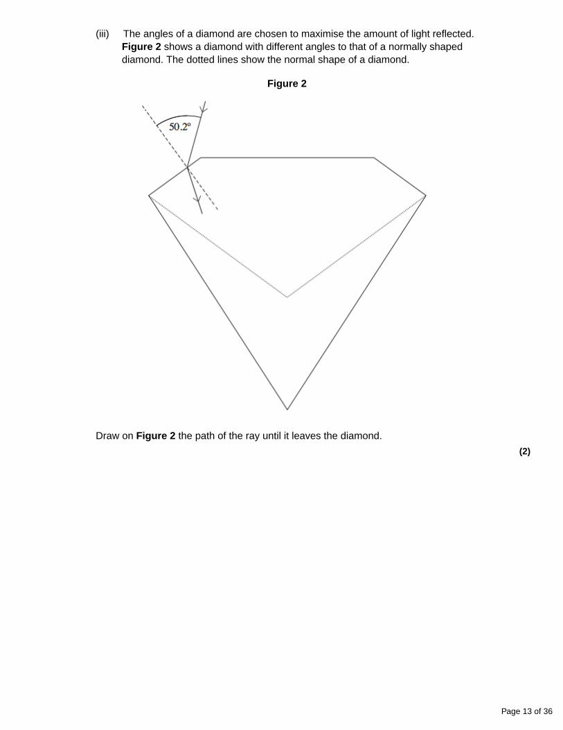
(iii) The angles of a diamond are chosen to maximise the amount of light reflected.Figure 2 shows a diamond with different angles to that of a normally shapeddiamond. The dotted lines show the normal shape of a diamond.
Figure 2
Draw on Figure 2 the path of the ray until it leaves the diamond.
(2)
Page 13 of 36

(iv) Moissanite is a transparent material with a refractive index of 2.67.
Discuss whether this material, if made to the diamond shape shown in Figure 1,would reflect light back more or less than diamond.
______________________________________________________________
______________________________________________________________
______________________________________________________________
______________________________________________________________
______________________________________________________________
______________________________________________________________
______________________________________________________________
______________________________________________________________
(2)
(b) Figure 3 shows an infrared ray entering an optical fibre. The refractive index of the core is1.55 at infrared frequencies.
Figure 3
(i) Calculate the speed at which infrared radiation travels in the core.
speed = ____________________ m s−1
(1)
Page 14 of 36

(ii) The wavelength of this infrared radiation is 1300 nm in air.Calculate the wavelength of infrared in the core.
wavelength = ____________________ m
(2)
(iii) State one reason for surrounding the core with cladding.
______________________________________________________________
______________________________________________________________
(1)
(Total 12 marks)
Musicians can use tuning forks to tune their instruments.A tuning fork produces a specific frequency when it vibrates.
Figure 1 shows a tuning fork vibrating in air at a single instant in time.The circles represent the positions of air particles in the sound wave.
Figure 1
8
(a) The tuning fork emits a wave that has a frequency of 0.51 kHz.
(i) State the meaning of the term frequency of a wave.
______________________________________________________________
(1)
Page 15 of 36

(ii) Air particles vibrate in different phases in the direction in which the wave is travelling.
Calculate the minimum separation of particles that vibrate 180° out of phase.
speed of sound in air = 340 m s–1
minimum separation ____________________ m
(3)
(b) A student sets a tuning fork of lower frequency vibrating at the same time as the 0.51 kHztuning fork in part (a).
The student detects the resultant sound wave with a microphone. The variation with time ofthe voltage generated by the microphone is shown in Figure 2.
Figure 2
(i) Explain why the two tuning forks are not coherent sources of sound waves.
______________________________________________________________
______________________________________________________________
______________________________________________________________
______________________________________________________________
(2)
Page 16 of 36

(ii) Explain why the resultant sound has a minimum amplitude at 50 ms.
______________________________________________________________
______________________________________________________________
______________________________________________________________
______________________________________________________________
______________________________________________________________
(3)
(iii) Calculate the frequency of the tuning fork that emits the lower frequency.
frequency ____________________ Hz
(3)
(c) A signal generator connected to a loudspeaker produces a sinusoidal sound wave with afrequency of 440 Hz.
The variation in air pressure with time for this sound is shown in Figure 3.
Figure 3
Page 17 of 36

A violin string has a fundamental frequency (first harmonic) of 440 Hz.
Figure 4 shows the variation in air pressure with time for the sound created by the violinstring.
Figure 4
(i) The two sounds have the same pitch but sound different.
What term describes the difference between the sounds heard?Tick (✔) the correct answer.
Frequency modulation
Octaves
Path difference
Quality
(1)
(ii) The complex sound in Figure 4 can be electronically synthesised.
Describe the process of electronically synthesising this sound.
______________________________________________________________
______________________________________________________________
______________________________________________________________
______________________________________________________________
______________________________________________________________
______________________________________________________________
______________________________________________________________
(3)
(Total 16 marks)
Page 18 of 36

The diagram shows a ray of light passing from air into a glass prism at an angle of incidence θi.The light emerges from face BC as shown.refractive index of the glass = 1.55
(a) (i) Mark the critical angle along the path of the ray with the symbol θc.
9
(ii) Calculate the critical angle, θc.
______________________________________________________________
______________________________________________________________
______________________________________________________________
______________________________________________________________
(3)
(b) For the ray shown calculate the angle of incidence, θi.
___________________________________________________________________
___________________________________________________________________
___________________________________________________________________
___________________________________________________________________
(2)
(c) Without further calculations draw the path of another ray of light incident at the same pointon the prism but with a smaller angle of incidence. The path should show the ray emergingfrom the prism into the air.
(3)
(Total 8 marks)
Page 19 of 36

Two waves with amplitudes a and 3a interfere.
The ratio is
A 2
B 3
C 4
D infinity
(Total 1 mark)
10
The diagram represents the experimental arrangement used to produce interference fringes inYoung’s double slit experiment.
The spacing of the fringes on the screen will increase if
A the width of the single slit is increased
B the distance XY between the two slits is increased
C a light source of lower frequency is used
D the distance between the single and double slits is decreased
(Total 1 mark)
11
Young’s two slit interference pattern with red light of wavelength 7.0 × 10 –7 m gives a fringeseparation of 2.0 mm.
What separation, in mm, would be observed at the same place using blue light of wavelength45 × 10–7 m?
A 0.65
B 1.3
C 2.6
D 3.1
(Total 1 mark)
12
Page 20 of 36

Figures 1 and 2 each show a ray of light incident on a water-air boundary. A, B, C and D showray directions at the interface.
Figure 1 Figure 2
13
(a) Circle the letter below that corresponds to a direction in which a ray cannot occur.
A B C D
(1)
(b) Circle the letter below that corresponds to the direction of the faintest ray.
A B C D
(1)
(Total 2 marks)
Which one of the following statements about stationary waves is true?
A Particles between adjacent nodes all have the same amplitude.
B Particles between adjacent nodes are out of phase with each other.
C Particles immediately on either side of a node are moving in opposite directions.
D There is minimum disturbance of the medium at an antinode.
(Total 1 mark)
14
Page 21 of 36

Mark schemes
Page 22 of 36

The student’s writing should be legible and the spelling, punctuation and grammar shouldbe sufficiently accurate for the meaning to be clear.
The student’s answer will be assessed holistically. The answer will be assigned to one ofthree levels according to the following criteria.
Answers may cover some of the following points:• (1) a wave and its reflection / waves travelling in opposite directions
meet / interact / overlap / cross / pass through etc
point (1) must be stated together i.e it should not be necessary tosearch the whole script to find the two parts namely the directions ofthe waves and their meeting
• (2) same wavelength (or frequency)• (3) node − point of minimum or no disturbance
points (3) may come from a diagram but only if the node is written infull and the y-axis is labelled amplitude or displacement
• (4) antinode − is a point of maximum amplitudepoint (4) may come from a diagram but only if the antinode iswritten in full and the y-axis is labelled amplitude or displacement
• (5) node - two waves (always) cancel / destructive interference / 180° phasedifference / in antiphase [out of phase is not enough] (of the two waves at thenode) [not peak meets trough]
• (6) antinode − reinforcement / constructive interference occurs /(displacements) in phase
• (7) mention of superposition [not superimpose] of the two waves• (8) energy is not transferred (along in a standing wave).
if any point made appears to be contradicted elsewhere the point islost − no bod’s
High Level (Good to excellent): 5 or 6 marksThe information conveyed by the answer is clearly organised, logical and coherent, usingappropriate specialist vocabulary correctly. The form and style of writing is appropriate toanswer the question.
6 marks: points (1) AND (2) with 4 other points which must include point (4) or the passagemust indicate that the wave is oscillating at an antinode
5 marks: points (1) AND (2) with any three other points
although point (1) may not be given as a mark the script can besearched to see if its meaning has been conveyed as a wholebefore restricting the mark and not allowing 5 or 6 marks
Intermediate Level (Modest to adequate): 3 or 4 marksThe information conveyed by the answer may be less well organised and not fully coherent.There is less use of specialist vocabulary, or specialist vocabulary may be used incorrectly.The form and style of writing is less appropriate.
4 marks: (1) OR (2) AND any three other points3 marks: any three points
Low Level (Poor to limited): 1 or 2 marksThe information conveyed by the answer is poorly organised and may not be relevant or
1
Page 23 of 36

coherent. There is little correct use of specialist vocabulary.The form and style of writing may be only partly appropriate.
2 marks: any two points1 marks: any point or a reference is made to both nodes and antinodes
[6]
(a) 3 subsidiary maxima in correct positions (1)
intensity decreasing (1)
2
2
(b) a single wavelength (1)
constant phase relationship/difference (1)2
(c) maxima further apart/central maximum wider/subsidiary maximumwider/maxima are wider (1)
1
(d) wider/increased separation (1)
lower intensity (1)2
(e) distinct fringes shown with subsidiary maxima (1)
indication that colours are present within each subsidiary maxima (1)
blue/violet on the inner edge or red outer for at least one subsidiarymaximum (1)
(middle of) central maximum white (1)3
[10]
Page 24 of 36

(a) maximum displacement from equilibrium/meanposition/mid-point/etc (1)
1
(b) (i) any one from:
surface of water/water waves/in ripple tank (1)
rope (1)
slinky clearly qualified as transverse (1)
secondary (‘s’) waves (1)max 1
3
(ii) transverse wave: oscillation (of medium) is perpendicular towave travel
or transverse can be polarised
or all longitudinal require a medium (1)1
(c) (i) vertical line on B ± 5° (1)1
(ii)
max 0, 180, 360 + min 90, 270 (1)
and line reaches same minimum and maximum every timeand reasonable shape (1)
2
Page 25 of 36

(d) appropriate use (1)
reason for Polaroid filter being used (1)
eg
Polaroid glasses/sunglasses/ to reduce glare windscreens
camera reduce glare/enhance image
(in a) microscope to identify minerals/rocks
polarimeter to analyse chemicals/concentration or type of sugar
stress analysis reveals areas of high/low stress/ other relevant detail
LCD displays very low power/other relevant detail
3D glasses enhance viewing experience, etc2
[8]
(a) same wavelength or frequency (1)(same phase or) constant phase difference (1)
2
4
(b) (i) narrow slit gives wide diffraction (1)(to ensure that) both S1 and S2 are illuminated (1)
(ii) slit S acts as a point source (1)S1 and S2 are illuminated from same source givingmonochromatic/same λ (1)paths to S1 and S2 are of constant length giving constant phasedifference (1)[or SS1 = SS2 so waves are in phase]
Max 4QWC 1
(c) graph to show:maxima of similar intensity to central maximum (1)[or some decrease in intensity outwards from centre]all fringes same width as central fringe (1)
2
[8]
(a) waves are reflected (from the oven wall) ✔1
and superpose/interfere with wave travelling in opposite direction/incidentwaves/transmitted wave ✔
NOT superimpose1
5
Page 26 of 36

(b) energy/amplitude is maximum ✔1
(chocolate melts at) antinode ✔if refer to node can still be awarded first mark
1
(c) clear evidence that used first and third antinode ✔can be from diagram
1distance from first to third antinodes = 0.118 ± 0.001 (m) ORdistance between two adjacent antinodes = 0.059 ± 0.001(m) ✔
mark for either value
carry their value forward for subsequent marks even if outsidetolerance
1
wavelength = 0.118 (m) ✔mark for using their wavelength (range 0.112 to 0.124)
1
frequency = 3.0 × 10⁸ /0.118 ✔
mark for use of v = fλ allow this mark if use 0.0591
frequency = 2.5 × 10⁹ (Hz) ✔
must be in range 2.40 × 10⁹ − 2.60 × 10⁹
if use 330 for speed lose last 2 marks1
(d) position of antinode/maximum energy/maximumamplitude/nodes (in food) continually changes ✔
must be clear antinode maximum energy/maximum amplitudechanges location
1[10]
(a) A wave transfers energy from one point to another ✔without transferring material / (causing permanent displacement of the medium) ✔ owtte
2
6
(b) (i) 0.6 (mm) or 0.60 (mm) ✔1
(ii) 0.080 (m) ✔Allow 1 sig fig
1
(iii) f = 1/T = 1/0.044 = 23 (Hz) ✔ (22.7 Hz)1
(iv) v = f λ = 22.7 × 0.080 = 1.8 (m s-1) ✔ (1.82 m s-1)
allow CE v = (biii) × (bii) but working must be shown
1 sig fig not acceptable1
Page 27 of 36

(c)
soundwaves aretransverse
soundwaves arelongitudinal
soundwaves caninterfere
soundwaves can
bepolarised
√ √ 1
(d) the wavelength would be smallersmaller spread in main peak or more peaks (between A and B)the central peak is higher (owtte)as the energy is concentrated over a smaller area (owtte)
reference to (sin θmin = λ/d)✔ ✔ ✔ any 3 lines max 3
Note that the marks here are for use of knowledge rather thanperforming calculations.
No bod if writing does not make increase or decrease clearlydistinct.
Marking should be lenient.3
[10]
(a) (i) sinC = 1/n = 1/2.42 ✔ (= 0.413)C = 24.4° ✔ (allow 2 or more sig figs)
Answer only gains both marks2
7
(ii) sin θdia = sin θair / n = sin 50.2 / 2.42 ✔ (= 0.317)
θdia = 18.5° ✔ (allow 2 or more sig figs)
Answer only gains both marks
Answer can be 18° or 19° depending on rounding2
(iii) TIR shown at bottom left surface ✔(If the reflected ray were extended it would passthrough the writing below the diagram between the ‘i’ in ‘it’ and the full stop at the endof ‘diamond’.) ray leaves bottom right surface either with an increased emergentangle or straight though if hitting normally ✔(The second mark is consequential on gaining the first mark)
acceptable emergent rays2
Page 28 of 36

(iv) it has smaller critical angle / critical angle is 22°allowing more / same number / greater chance / increased probability of TIR’soccurringgreater/same sparkle ✔✔ max 2
‘reflect more’ is insufficient for a mark2
(b) (i) ccore = cair / n = 3.00 × 10⁸ /1.55 = 1.9 × 10⁸ (ms-1)✔(1.94× 10⁸ ms-1)
1 sig fig is not acceptable if no other answer is given1
(ii) (n = cair / ccore = f λair / fλcore =λair /λcore )
λcore = λair / n or 1300 × (10-9) / 1.55✔= 8.4 × 10⁻⁷ (m)✔(8.39 × 10⁻⁷ m or 839 nm)
The first mark is for the equation or substitution ignoring powers of10 errors
1st mark can be gained from calculating the frequency ( f = 3.0 ×10⁸ / 1300 × 10-9 = 2.3 × 10¹⁴ (Hz) which then can be used to findthe the wavelength
Using this method the answer can range between 8.4 × 10⁻⁷ → 8.7× 10⁻⁷ (m) and consider ecf’s from (b)(i)
2
(iii) protects the core (from scratches etc)prevents crosstalk / stops signal crossing from one fibre to another / increases criticalangle / reduces pulse broadening / reduces smearing / prevents multipath dispersionallows fibre to be supported / touched (without losing light)
✔any one point
Preventing signal loss is not enough for the mark.1
[12]
(a) (i) Number of complete waves passing a point in one second / number of completewaves produced by a source in one second / number of complete vibrations(oscillations) per second / number of compressions passing a fixed point persecond
1
8
(ii) 180° phase difference corresponds to ½ λUse of v = fλ with correct powers of 100.33 (m)
3
(b) (i) Do not have the same frequencydo not have a constant phase difference
2
(ii) Waves meet antiphaseUndergo superpositionResulting in destructive interference
3
Page 29 of 36

(iii) T = 100 ms
Use of T = 1 / f or beat frequency (∆f) = 10 Hz500 (Hz) (allow 510 –their beat frequency)
3
(c) (i) Only box ticked: Quality1
(ii) Add regular alternating voltages togetherWith appropriate amplitudesWhere frequencies of voltages match the harmonics of sound / where frequenciesare multiples of 440 Hz
Allow 2 for sampling sound (at twice max frequency ) B1
Convert to binary ( and replay through D to A converter). B13
[16]
(a) (i) θc marked (1)
(ii) sin θc = (1)
θc = 40.2° (1)3
9
(b) n = (1)
(θ2 = 90 – 75.2 = 14.8°)
θ1 (= sin–1{1.55 sin 14.8}) = 23.3° (1)2
(c) Mark scheme not available.3
[8]
A
[1]10
C
[1]11
B
[1]12
(a) A
B1
(b) D
B1
[2]
13
Page 30 of 36

C
[1]14
Page 31 of 36
Examiner reports
Almost all students made a good effort at answering this question and almost all of those knewthat standing waves are constructed from two waves. This being the case it was appropriate thatthis question was the basis of the quality of written communication assessment in thisexamination. Weaker students often spent too long setting the scene. They gave details of theapparatus and explained how the string was plucked or vibrated before the bullet points wereaddressed. Often at this stage these were answered with very brief responses that gave verylittle detail. The middle ability group of students fared much better. They could describe whatnodes and antinodes were and how they came about in terms of the interference of two waves.What was often missing was the fact that the two waves that superpose have the samefrequency or wavelength. Many of this group and a large percentage of the top ability groupunderstood that an antinode was a maximum of the motion but they referred to the maximumdisplacement rather than the maximum amplitude. A couple of points separated this top groupfrom the middle students as well as the quality of the structure of their writing and spelling. Firstthey referred to the waves superposing unlike the majority who thought the waves superimposedon each other. Secondly, they sometimes included a point about the lack of energy transmissionin a standing wave.
1
Most candidates gained at least one mark in part (a) for showing that the intensity of peaksreduced with distance from the centre. However, many did not recall the key difference betweenthe pattern for single and double slits – the single slit pattern has a central maximum which isdouble the width of the subsidiary maxima.
There were many correct definitions of monochromatic and coherent in part (b). A few stated‘same colour’ for monochromatic and ‘in phase’ for coherent. Neither of these were accepted.
In part (c), many candidates incorrectly used the equation for two slits to show that the maximawere further apart. This was not penalised since an explanation was not asked for.
2
Many candidates got part (d) the wrong way around, saying that the fringes would be moreclosely spaced and more intense. There seemed to be some guess work evident here.Candidates need to be able to describe the appearance of the single slit pattern and be aware ofhow it will change for different wavelengths, slit widths and for monochromatic and white light.Some teachers introduce the equation for the single slit although it is not in the specification. Thisis not necessary but can certainly help the more mathematically minded students. To illustratethe change in the pattern, a simple demonstration can be carried out with a red and a green lasershone through the same slit onto a screen.
A pleasing number of candidates produced very detailed and high quality answers to part (e),with many gaining all three marks. Some drew a graph of intensity, which did not gain a mark onits own.
Page 32 of 36

In part (a), the strict definition of amplitude was expected. Candidates needed to say ‘maximumdisplacement’ and then indicate in some way that this was relative to the equilibrium position.
The majority, however, chose to define amplitude as the distance between the centre and thepeak.
For part (b) (i), the majority of candidates could not give an example of a transverse wave otherthan electromagnetic waves. Most gave a form of electromagnetic radiation (most commonly‘light’) or even sound. Common answers that were accepted included ‘water waves’, ‘waves onstrings’ or ‘s-waves’.
Most candidates realised that a comparison between the direction of wave travel and theoscillation of the medium was a good way to answer part (b) (ii). It was common, however, forcandidates to struggle to express this clearly. The most common error was to say that atransverse wave ‘moves’ perpendicular to the direction of wave travel rather than ‘oscillation isperpendicular to direction of wave travel’.
3
The vast majority of candidates found part (c) (ii) very straight forward.
The majority of candidates had no problem with part (c) (ii). The exact shape of the line was notimportant as long as the maximum and minimum intensities appeared in the right place.
There were many very good answers to part (d), such as ‘sunglasses/ski goggles reduce glarefrom light reflected from water/snow’ and ‘a camera filter reduces unwanted reflections’. Commoninadequate responses included saying that polarising sunglasses ‘reduce light intensity’ becausethe lenses are ‘darker’, or that polarising filters reduce UV.
Whilst it was generally recognised in part (a) that coherent sources provide waves of the samewavelength (or frequency), the requirement about phase was less well understood. The commonanswer was that the waves must be ‘in phase’, whilst the accepted answer was that there has tobe a constant phase relation between them. Although monochromatic sources that are in phasewill be coherent, coherence does not require the sources to be in phase. In part (b), the singlemonochromatic source is the reason for fulfilling the same A criterion; this was correctly quotedby most. Satisfactory explanations of how the phase criterion is satisfied were very rare indeed,with few references to the paths SS1 and SS2.
Had part (c) required candidates to sketch Young’s fringes, there can be no doubt that theresponses would have been much more rewarding. Most candidates were unable to translatetheir knowledge of the appearance of a familiar phenomenon into the required intensity/positiongraph. Near the centre of the pattern, the fringes are all of very similar intensity and all shouldhave been drawn with the same width as the central fringe. The majority of wrong answersshowed either the single slit diffraction pattern, or fringes having the same width as the centralone but with much lower intensity.
4
Page 33 of 36

This question about the formation of stationary waves in a microwave oven was answered wellby a good proportion of students. In part (a) the idea of reflection taking place was clearly statedin the majority of answers. The second marking point explaining how this resulted in the reflectedand incident wave superposing was more discriminating. A significant proportion of studentsstated that the waves superimposed rather than superposed. Part (b) was only fully answered bythose students who, having identified the melted chocolate positions as antinodes were then ableto explain that this is where the amplitude of the wave was a maximum. Weaker responsestended to identify these positions as nodes or did not link the melted chocolate to stationarywaves at all. Part (c) was a five mark calculation and this produced very good discrimination.About a third of students were awarded 4 or 5 marks. To obtain full marks students were requiredto give a clear indication, either on the diagram or in their working, that they had measured thedistance between the first and third dot rather than measuring from the first to second dot andthen doubling. It was sometimes hard to establish exactly what students had measured and itshould be appreciated that showing full working in these extended calculations is very important.A lot of vague answers were seen to question 2.4 and it was the physics that needed to beexplained. A common response was ‘to cook the food evenly’ and this was not seen as a physicsexplanation.
5
(a) For a majority this was a piece of work that was never committed to memory and the markswere low. Only about half the students scored the mark about the wave being able totransport energy from one place to another. Then only a small subgroup of these studentsreferred to matter not being transported.
(b) (i) Almost all students found this basic question straightforward.
(ii) Almost all students found this basic question straightforward.
(iii) Again the vast majority of students had no problems but a few got into difficulty inreading the time scale correctly.
(iv) The equation for velocity was known by almost all the students and most scored themark.
(c) A majority of students chose the correct responses but there was a significant numbertempted away by one or more of the distractors.
(d) This question discriminated between students very effectively. Many did appreciate that ahigher frequency meant a shorter wavelength. This in turn had the effect of compressingthe diffraction pattern. Students had some difficulty in expressing this idea. Instead ofsimply saying the central peak was narrower they might say the wave is shorter. Only thevery able students obtained a third mark. Most said the pattern shown would have thesame height because the amplitude was the same.
6
Page 34 of 36

(a) Both the geometric optics calculations in parts (i) and (ii) were done very well by students.
(iii) This question gave a good spread of marks. Although a majority scored well, errorswere seen at each stage. The most common error was to simply copy whathappened in the figure, which resulted in an incorrect angle of reflection on the firstsurface. In other cases the reflections were drawn from the dotted lines in the figure.The other common mistake was for the TIR on the first surface to be drawn with theangle of reflection not looking close to the angle of incidence.
(iv) This question was very discriminating. More able students knew exactly what theywere doing but many others either simply suggested it would reflect more or less andgave the reason as the refractive index was higher. Even when they related therefractive index to the critical angle they often related this to the conclusion in thewrong way. For example they may have said 'lower critical angle so the rays of lightare less likely to be reflected.
(b) (i) This straightforward calculation was done well by a majority.
(ii) This was again done well but it gave rise to a few more errors compared to theprevious part.
(iii) There was a huge number of correct possible answers for using cladding and amajority of students chose one of them. However a significant number of studentsthought that the cladding made TIR more likely or prevented light escaping from thecore.
7
Page 35 of 36

(a) (i) Acceptable definitions were given by a good majority of the students. Those whofailed to produce a satisfactory response usually omitted reference to time.
(ii) Most gained credit for the use of v = fλ . The common errors were ignoring the k inkHz and not calculating λ/2.
(b) (i) This question was a ‘twist’ on a commonly asked question that requires students toexplain what is meant by waves being coherent. This question required students to identifythat the tuning forks had different frequencies and would not have a constant phasedifference when they arrive at a point so would not be coherent. This proved to be toochallenging for many students.
(ii) This was poorly done and fewer than half the students were able to give at least oneacceptable point worthy of credit and there were relatively few who gained full credit.One can only speculate that students have difficulty understanding interference thatoccurs due to changes in phase difference that take place at a point with time as isthe case in this instance.
(iii) A high proportion of the students gained credit for use of f = 1/T and many of thesearrived at the correct beat frequency. Many did no more than this and relatively few ofthese went on to calculate the correct frequency of the fork that emitted the lowerfrequency.
(c) (i) Almost three quarters of the students selected the correct response to this question.
(ii) Relatively few appreciated the meaning of synthesis of sound ie the process ofadding together sinusoidal waves of appropriate frequencies and amplitude toproduce a required sound. Students were given compensatory credit for explainingthe process of sampling a sound and storing it digitally.
8
Not for the first time in the history of this paper the optics question proved to be the most difficultin the paper. Only the best candidates could identify the critical angle. Candidates were a littlemore successful in calculating the critical angle but the units of degree were frequently omitted.In (b) candidates failed to get the correct answer because they did not calculate the angle in theglass as (90.0° – 75.2°) and often did not use the correct equation. The ray diagram in part (c)was done badly by a vast majority of candidates and the average mark was about one out ofpossible three.
9
Although many candidates scored full marks on this simple opening question, there was asignificant number who could not relate the diagram on the paper to the practical situation of lightrays moving across the boundary between two media.
13
Page 36 of 36


![ASSESSMENT UNIT PH2: WAVES AND PARTICLES · 2015-09-29 · stationary wave is shown as if it were a stationary wave on a stretched string.] [2] 2L n (b) For a particular semiconductor](https://img.pdfslide.us/doc/110x75/5f75d6c79631da5cc712baf4/assessment-unit-ph2-waves-and-particles-2015-09-29-stationary-wave-is-shown-as.jpg)