Embed Size (px)
Citation preview

Athens Journal of Technology and Engineering - Volume 8, Issue 3, September 2021 –
Pages 259-282
https://doi.org/10.30958/ajte.8-3-4 doi=10.30958/ajte.8-3-4
A Software Model for Parameters Affecting the
Dimensions of Reinforced Concrete Prefabricated Facade
Elements
By Mustafa Tosun* & Enes Yasa
±
In this study, a model software of a computer program related to determining
dimensional behavior, which will contribute to the multi-layered units used on
the facade of industrial buildings to be standardized, has been prepared. By
means of this model software, the factors determining the width (A), the height
(h) and the section (d) of the units of a building facade, could be evaluated.
These factors, at the same time, from the dimensions of building facade units
providing “thermal insulation, sound insulation statically behavior and
coordination dimension of facade unit.” In the program (named as MT2
Prefabrike), these four factors could be evaluated by providing the optimization
in sequence and within themselves. Thus, by developing a new method of
approach in the standardizing of facade units, apart from the visible
characteristics of the units, the idea of standardizing the performance and
behavior expected from the units, are put forward. In the model program formed
with this idea, before producing of the facade units, the optimization is to be
provided by analyzing the factors which are effective in giving dimension to the
units, in abstract condition (computerized).
Keywords: a model software, building facade unit, prefabrication, thermal and
sound ınsulation, static behavior analysis, the facades of ındustrial buildings
Introduction
There are many studies on building modeling. They bring all the stages of
construction closer to a predictable system. Building information modeling (BIM)
is one of the most promising recent developments in the architecture, engineering,
and construction (AEC) industry. With BIM technology, an accurate virtual model
of a building is digitally constructed. This model, known as a building information
model, can be used for planning, design, construction, and operation of a facility.
It helps architects, engineers, and constructors visualize what is to be built in a
simulated environment to identify any potential design, construction, or
operational issues. BIM represents a new paradigm within AEC— one that
encourages integration of the roles of all stakeholders on a project. The
architecture, engineering, and construction (AEC) industry has long sought out
techniques to decrease project cost, increase productivity and quality, and reduce
project delivery time. Building information modeling (BIM) offers the potential to
achieve these objectives (Azhar et al. 2008). When completed, the building
*Associate Professor,
Konya Technical University, Turkey.
±Associate Professor, Istanbul University, Turkey.

Vol. 8, No. 3 Tosun & Yasa: A Software Model for Parameters Affecting…
260
information model contains precise geometry and relevant data needed to support
the design, procurement, fabrication, and construction activities required to realize
the building (Eastman et al. 2008).
The future of BIM is both exciting and challenging. It is hoped that the
increased use of BIM will enhance collaboration and reduce fragmentation in the
AEC industry and will eventually lead to improved performance and reduced
project costs (Azhar 2011).
This study conducts analyses in order to determine (static) behaviors in terms
of thermal, sound and conveying features expected from an element while forming
the element cross-section in order to make use of ―Coordination Dimensions‖ in
defining the dimensions of reinforced concrete pre-fabricated facade elements
which are used in industrial structures‘ facades (Wang-Dong et al. 2011). A
computer software was created in order to conduct these analyses. For this
software, Delphi was used. Delphi is a visual software development tool which
was developed by Borland. It is Pascal-based and object-oriented (Lantim 1998).
In the study, the ―MT2 Prefabrike‖ program was prepared for dimensional
analysis.
With the ―MT2 Prefabrike‖ analysis program, analyses can be done on
―thermal insulation, sound insulation, sizing and conveying properties (static)‖ for
non-conveying reinforced concrete pre-fabricated and multi-layered facade
elements used in Industrial structures‘ facades. For this purpose in this program, a
―Program Flow Diagram‖ was prepared which indicates the relationship and
transitions among data (Figure 1). This developed model works with the system
outlined in the flowchart in Figure 1 and reaches the result. The model is
definitively completed when all the stages in Figure 1 are concluded in accordance
with the calculations.
Figure 1. Flow Diagram for “MT2 Prefabrike” Analysis Program

Athens Journal of Technology & Engineering September 2021
261
Model Introduction and Application of Model
The limitations which define the dimensions of reinforced concrete pre-
fabricated industrial structures should be regarded as data intended to standardize
the element (Cansun 1989). The element has three dimensions, namely horizontal
dimension (width), vertical dimension (height) and cross-section (Christiane et al.
2018).
Factors Which Affect the Cross-Section Size of Facade Elements
In the ―MT2 Prefabrike‖ program the analyses (thermal insulation, sizing,
static and sound insulation) were represented in separate menus and these were
optimized in their interactions among each other.
Heat Insulation of Facade Elements
Heat transmission coefficient in construction elements is expressed with the
―U‖ symbol and its value is explained as ―W/M2k‖. It is expressed in ―watt‖ units
(Joule/sec). It describes air which transitions from a 1 m2 surface to another
surface under 10 C0 temperature (TSE 825 1999, Chudley 1994).
For this reason, ―MT2 Prefabrike‖ was prepared in line with the ―thermal
insulation requirements for buildings‖ directive which was published on 18
December 2013. Separating Turkey into five zones in terms of thermal insulation
applications (Table 1), the directive prescribes that structures be insulated in
accordance with environmental conditions and properties, and indicated of such
insulation by drawing up a heat insulation project (TSE 825. 1999).
Table 1. Heat Transmission Coefficients (U) of Facade Element According to
Zones (Eriç 1994) UD (W/m
2K) UT (W/m
2K) Ut (W/m
2K) UP (W/m
2K)
Region-I 0.66 0.43 0.66 1.8
Region-II 0.57 0.38 0.57 1.8
Region-III 0.48 0.28 0.43 1.8
Region-IV 0.38 0.23 0.38 1.8
Region-V 0.36 0.21 0.36 1.8
Example Solution Using the ―MT2 Prefabrike‖ Software-Forming Facade
Element Layers
The starting point for formation of the layers to be used in the whole analysis
of the reinforced concrete pre-fabricated element is a selection in the main
―thermal analysis‖ menu in the program. After this selection, an array of windows
will be displayed on the screen. In the first window, the number of layers, which
form the cross-section of the element, is entered (Figure 2). We can form a layer
cross-section example like below, using values for material, thickness and related
heat conductivities (Table 2).

Vol. 8, No. 3 Tosun & Yasa: A Software Model for Parameters Affecting…
262
Figure 2. Layer Quantity Window for the Element in the “MT2 Prefabrike”
Program
Table 2. Sample Cross-Section Data Used in the Program
Layer Material Heat Conduc.(λ)
Thickness(d)
1st Layer ................... C(35) concrete ..... …….. 1.75 kcal/m2hCº
........................... 0.07 m.
2nd Layer ................Thermal İnsulation .......... 0.035 kcal/m2hCº ...........
................0.03 m.
3rd Layer ......................C(35) concrete ……..... 1.75 kcal/m2hCº
........................... 0.10 m.
Figure 3. Sample Cross-Section of the Element, to be Analyzed in the “MT2
Prefabrike” Program

Athens Journal of Technology & Engineering September 2021
263
Together with the reinforced concrete pre-fabricated facade element‘s layers,
the ―Heat Conductivity Coefficient (λ)‖ will be automatically given in selection of
each material from the material window, as seen in Figure 1. Afterwards, material
thickness (m.) must be entered. Formation of the facade element‘s layers will also
provide a representation for each material in the symbol window. Therefore the
material can be recognized in the analyses; wall section layer has been given in
Figure 3.
Thermal Zones
The program‘s menus feature a ―thermal zone‖ parameter. In order to
determine the thermal zone where the industrial structure is to be constructed, the
only action required is to select the name of construction zone from the ―Thermal
Zone‖ parameter. The program will take this zone as the base and then show the
―Heat Transmission Resistance (R=1/λ)‘‘ m2hC˚/kcal‖ value for the zone, of
which value can be used in inquiries.
Thermal Analysis
The analysis on expected thermal behavior from the facade element of
reinforced concrete pre-fabricated industrial structures, that is, determining
whether the element has suitable insulation according to selected thermal zone, can
be conducted via pressing the ―Analysis‖ button (Figure 2). The equation uses the
below formula:
Ro = 1 / = (d1/) + (d2 / ) + (d3 / ) (1)
Figure 4. Thermal Insulation Calculation Results in the “MT2 Prefabricated”
Program

Vol. 8, No. 3 Tosun & Yasa: A Software Model for Parameters Affecting…
264
Analysis Results
This section of the program is shown in the menu called ―Analysis Results‖
where all the results are displayed and the print outputs can be obtained. Here are
the names of the materials that make up the layer, their thickness, the heat zone
and the information that evaluates the suitability of the result. The results of the
analysis are shown in Figure 4.
In the MT2 evaluation program, necessary feedbacks can be made by
considering a dynamic structure for the case where appropriate values for the
building site Heat Zone do not come out. The program has a ―print‖ command
window in which the analysis results can be printed. You can then proceed to the
sizing analysis with the ―Next‖ command button or you can exit the program with
the ―Close‖ command button.
Factors Which Affect the Height of Facade Elements
In reinforced concrete pre-fabricated industrial structures, the height of facade
elements can be varied according to the structure‘s height and the element‘s
position in the facade. For this reason, factors such as the height of the industrial
structure, facade design and transport of the elements affect the outcome.
Factors Which Affect the Width of Facade Elements
The factors which affect the widths of reinforced concrete prefabricated
industrial structures also include the factors that are to be evaluated in the
computer program. These are factors such as the opening where the element will
be positioned, joint width and joint tolerances, number of elements in the opening
and whether to position the elements on the front or behind carriers. In facade
element design, one of the most important factors which affect element width is
the element‘s design alternatives. The design of the facade element is also directly
related to the design of the building facade. Named ―Modular Coordination‖, the
system was derived from the Latin word ―Modulus‖ (small scale) (Figure 5)
(Escrig et al. 1996).
Artificial Neural Networks are systems made up of artificial nerve cells that
imitate problem solving skills of biological nerve cells by communication and that
only living things possess (Montali et al. 2017). These networks discover the
connections among attributes inside the samples and can make it possible to
classify a sample that they have never encountered before. The discovery process
of connections among previous samples is called the training of artificial neural
networks. The classification plays an important role for the accuracy of results.
However, when an appropriate solution is found for network classification
during the process, it can be possible to focus on this solution. At this point, the
artificial neural network algorithm is optimized with the help of the firefly
algorithm, which is a powerful and fast optimization algorithm, in order to
decrease this sticking possibility (Montali et al. 2017).

Athens Journal of Technology & Engineering September 2021
265
Figure 5. Basic Module (M=10)
Reinforced concrete pre-fabricated facade elements are placed in (n) quantity
into the shaft opening of the carrier system, therefore entering this structure. In the
dimensional coordination, shaft opening (D) is obtained with multiple repetitions
(n) of the basic module (M); (nxM) (Figure 5). Facade elements which are in
relation to another, that is, which enter dimensional coordination, should be within
coordination lines and their coordination dimensions should also be equal (Figure
6). It is called the ―position line‖ which determines the location of the facade
elements in dimensional coordination. We can express the position of the facade
element in dimensional coordination in the following terms:
D = n x M Shaft opening (cm)
n = Basic module coefficient (quantity)
M=Basic Module (cm). Can be M, 2M, 3M, or 1.5M, 0.75M, 0.5M, etc. times
of the basic module (Şener 1990).
The reinforced concrete prefabricated facade elements, which are used in
industrial structures‘ facades, fit into the modular coordination and are placed into
the shaft opening obtained. In order to make the facade element in a computer
environment suitable to the needs of decision-makers, it is necessary to design in
the direction of modular coordination principles. Elements are sized using M=10
cm, which is the basic module.
Figure 6. The Position of Prefabricated Facade Element on the Modular Grid
In order to be able to decide how many (n) multi-layered elements to produce
and what the mould size, that is the net width (A), would be in reinforced concrete
pre-fabricated, the element's position in the facade within the element design has

Vol. 8, No. 3 Tosun & Yasa: A Software Model for Parameters Affecting…
266
to be determined. For this, two design alternatives, which are fundamental to the
MT2 Prefabricated Computer program and affect the determination of the widest
dimension of the element, are taken into consideration.
Design of Prefabricated Facade Elements Between Columns
If reinforced concrete prefabricated facade elements are designed to be
between load-bearing columns (Figures 7 and 8) below equation can be used,
depending on the distance between columns, in order to calculate the net width of
the element (A):
(2)
d=Joint width
D=Shaft opening measurement of load-bearing columns (cm)
A=Pre-fabricated facade element size
n=Number of elements
b=Column size
Figure 7. Designing Prefabricated Facade Elements Between Columns
Figure 8. Positioning Prefabricated Concrete Facade Element Between Columns
In this program, the net element size (A) can be recalculated by changing the
number of facade elements (n). The element size will then be calculated as

Athens Journal of Technology & Engineering September 2021
267
―Facade Element Net Size‖ A=130.6 in the top right corner of the program. The
program contains the ―Analysis Results‖ section which shows all the data of the
facade element and the net element size (A) according to this data. The program
also has a graphical representation of the facade design of the facade element, with
all the values written on the element (Figure 8).
When the process of finding the maximum size (A) of the program element is
completed, the ―Next‖ button can be pressed to move to the next step, or the
analysis results can be printed out with the ―Print‖ command. In addition, you can
return to thermal analysis with the ―Back‖ command for optimization at element
size. You can use the ―Close‖ message to exit the program.
Designing Reinforced Concrete Prefabricated Facade Elements on the Front of
the Columns
If reinforced concrete pre-fabricated facade elements are designed to be on the
front of load-bearing columns (Figure 9), below equation can be used, depending
on the distance between columns, in order to calculate the net width of the element
(A):
(3)
d=Joint width
D=Coordination size (Shaft opening size)
A=Pre-fabricated facade element size
n=Number of elements
Figure 9. Designing Reinforced Concrete Prefabricated Facade Elements on the
Front of the Columns
In this part of the program, an assessment can be made to determine the width
dimension of the element directly involved in the production, lifting, transport,
assembly processes of the front elements used in the reinforced concrete
prefabricated industry structures and tool capacities.
In this part of the program, an assessment can be made to determine the width
dimension of the element directly involved in the production, lifting, transport,
assembly processes of the front elements used in the reinforced concrete
prefabricated industry structures and tool capacities.

Vol. 8, No. 3 Tosun & Yasa: A Software Model for Parameters Affecting…
268
Analysis Results
The net element size (A) found at the end of the sizing analysis of reinforced
concrete prefabricated multi-layer elements used in the facades of industrial
structures will be visually included in the analysis results of the program. The
―Analyze‖ window will show the facade design, the visual results and the results
and evaluations of all the calculations. These data are shaft distance, coordination
size, column width (b), joint tolerance width and calculated net element size (A) to
be obtained from the mould.
Load-Bearing (Static Structure) of Facade Elements
From the production stage, a facade element needs a cross-section fitting that
resists loads such as lifting, transport and wind effects. In order to resist these
loads, the carrier inner-layer forming the element, the insulating material between
and the outer layer move together.
This connection, which forms the cross section of the facade element, must
form a rigid structure against the above static forces. In this section, the inner load-
bearing layer of the element will be dealt with, which counteracts the static factors
affecting the cross-sectional dimension of the element, the lifting forces, the loads
that occur during transport and the wind effects.
Lifting Control
The position where the reinforced concrete pre-fabricated facade elements,
which are used in industrial structures' facades, receive the most deflection risk,
occurs at the moment when the element has to be lifted.
Facade elements are lifted from their hooks and a substantial load occurs in at
this moment. This load delivers an equal momentum to both ends of the facade
element, thanks to a balanced positioning of lifting hooks (Figure 10).
Figure 10. Cross-Section and Lifting Points of Prefabricated Concrete Facade
Elements
Equations 4, 5 or 6 can be used to calculate the lifting force received by the
element (Figure 11).
σ=Tensile Stress

Athens Journal of Technology & Engineering September 2021
269
σ=M/W (Kg/cm2) (4)
Where:
Fck=300 kg/cm2 fct=150 kg/cm
2
-M=(q x l2)/2 (5)
W=(L x D2)/6 (6)
l=Abutment distance (cm)
L=Element width (cm)
D=Element cross-section (cm)
q=Spread load (t/m)
Figure 11. Lifting Moments in Prefabricated Concrete Facade Elements
With the tensile stress calculation there will be an analysis of whether or not
cracks will occur during lifting. This method can also be used in the computer
program and the tensile strength can be calculated using equation 7:
[σ < 0.9 √ fci ] < 11.02 (Kg/ cm2)] (7)
Where:
0.9 √ fci=Maximum tensile stress for prestressed joint sections
fci=Pressure value on day ―I‖ (kg/cm2)
i=The age of the concrete at the moment of removal from the mold (Bakır 1990).
Bearing Control
After the production of the reinforced concrete pre-fabricated multi-layer
facade elements used on the facades of industrial buildings, static calculations of
the hooks must be made in order to be able to meet the loads coming to the
transport hooks at the moment of transport to the construction site. This calculation
is carried out as below for the ―R‖ hooks seen in Figure 12 (Bakır 1990).

Vol. 8, No. 3 Tosun & Yasa: A Software Model for Parameters Affecting…
270
Figure 12. Load on Bearing Hooks of Prefabricated Concrete Facade Elements
R=G/tons
Static load coeff.=4
R total= 4x R tons
R=Load on Bearing Hooks (tons)
G=Facade element weight (tons)
Wind Control
One of the problems facade elements can encounter after installation are
Wind Impacts. The load resulting from Wind Impacts should be taken into account
in the sizing analysis, although it is very small relative to the effect at the time of
lifting (Figure 13).
Figure 13. Wind Load on Prefabricated Concrete Facade Elements
Calculations for the Tie Bars
In formation of cross-sections for Prefabricated Concrete Facade elements, tie
bars are used between the outer layer and the inner layer. When these bars are
placed, it is important that the cross-section is sufficient. Also, care must be taken
to ensure that where the steel rods are placed have sufficient strength to support
the building envelopes during lifting of the element. The highest pulling force on
the tie rods will occur when the element is being lifted from the mould.
In ―MT2 Prefabrike‖ static analysis program menu, at the very top, the
element's total weight coming from its cross-section will be shown in two

Athens Journal of Technology & Engineering September 2021
271
windows; the building envelope weight (Outer layer + Inner layer), and insulation
weight.
Next there will be the window containing fck. and fct. values, which vary
according to concrete class (C-35) (Figure 14). These values are decided upon
during the ―Thermal Analysis‖ stage by selecting concrete class during formation
of building envelope layers. This is because all data of the program work in
integration with one another.
Lifting Control Analysis
An analysis is made on the forces the element gets subjected to while it is
lifted from the mould. This analysis is then shown in a window in the program
menu. To do this, simply select the ―Calculate‖ command in the lifting control
analysis. This is because all data required for Lifting Control Analysis is also used
commonly by ―Thermal Analysis‖ and ―Sizing Analysis‖.
Figure 14. Data Connected to Concrete Class Used in Static Analysis
Bearing Control Analysis
In bearing control analysis, the hook fitting, which is expected to lift the
element during the bearing action, will be calculated. The result will then be used
to give the user the quantity of hook fitting and fitting diameter in the program
menu. The result will be displayed in the ―Hook Fitting‖ window. Since all values
are taken from ―Temperature and Sizing‖ analyses, here it will suffice to just use
the ―Calculate‖ command button.

Vol. 8, No. 3 Tosun & Yasa: A Software Model for Parameters Affecting…
272
Wind Control Analysis
In order to determine reinforced concrete prefabricated facade elements‘
behavior against wind loads, calculation results are displayed in the ―Wind
Control‖ window. If wind control calculations yield a result that is plausible
against given dimensions, the program will not display any error messages. If
M/W<0.9 fci, this means that a plausible size is selected and there will be no need
to revise the size in the program.
Analysing Tie Bars
Diameters and quantity of the tie bars, which provide connection between
inner and outer building envelope of reinforced concrete prefabricated facade
elements, are displayed in a window in the program.
Analysis Results
The inquiries made with the ―Static Analysis‖ of reinforced concrete
prefabricated multi-layered facade elements used in industrial structures‘ facades
are displayed in the ―Analysis Results‖ window in the program. Here, the
evaluation is based on whether any cracks will occur, using lifting and wind
analyses. The number and diameter of hook fittings and binding reinforcements
are also displayed in the Analysis window. If there is a negative result such as
cracking of the concrete in evaluation, changes can be made to the size parameters
of the element and the operation can be continued until a positive result is
obtained. These parameters are: concrete class and the quantity of hook fittings—
if cracking of the facade element cannot be prevented with these parameters, the
user should go back to the sizing analysis and make changes in element quantity
(n), element height (h) parameters. Then the statistical analysis is complete.
Afterwards, pressing the ―Next‖ command button in the right bottom corner for
further analyses or the current analysis can be printed out using the ―Print‖
command.
Sound Insulation of Facade Elements
The term ―sound‖ is used for vibrations in the 16-20,000 Hz frequency range
which the human ear can hear. ISO-acknowledged values are 20-20,000 Hz (ISO
1990).The National Academy of Sciences- National Research Council, Committee
on Hearing, Bioacoustic Biomechanics (CHABA) determined sound emitting
threshold for soundwave frequency zone as 20-12,000 Hz (Young 1988).
Sound insulation materials that form a cross-section of the ―Reinforced
Concrete Prefabricated‖ multi-layer facade elements provide insulation at different
levels. In order to be able to make this decision, optimum decisions have to be
given among some criteria. The most important of these is the level of sound
proofing desired. If people work within the industry structure, the following levels
of continuous, maximum volume will be needed depending on the hours of
operation.
06.00 – 22.00 < 60 dB

Athens Journal of Technology & Engineering September 2021
273
22.00 – 06.00 < 50 dB (Young 1988).
For ease of understanding the effects of sound levels, the sound level (dB) of
the sound sources given in Table 2 should be known. Table 3 gives acceptable
background sound levels for human activities (Beranek and Ver 1992). In
reinforced concrete prefabricated industry structures, the frequency with the
largest amplitude, produced by two layers forming the cross-section by pressing
against the insulation layer between, is called ―natural frequency‖ (fr)
(Simultaneous Vibration Frequency). The value of natural frequency depends on
the zone weights of the two layers and the dynamic rigidity (s') of the insulation
layer between and fr can be calculated using the below equation:
fr =500 √ s‗ [ (1/M1) + (1/M2)] (Hz) (8)
Where:
fr= Natural frequency (Sim. Vib. Freq.) (Hz),
s'=Insulation layer dynamic rigidity (kp/cm3)
M1 and M2=Zone weights of outer and inner layers (kg/m2) (Table 6).
Dynamic Rigidity (s') of the insulation layer in the equation is called the elasticity
of the insulation layer placed between the layers and used for sound damping.
s'=E/a (kp /cm3)
Where:
E=Dynamic elasticity module (kg/cm2) (Table 6)
a=Thickness of intermediate layer or space (cm)
Table 3. Sound Levels from the Noise Sources (dB) (Young 1988) Very light: 20 dB Whisper, leaf rustling, background noise in broadcast studios
Light: 30 dB Speaking with low voice, auditorium environment
Light: 40 dB Private office, quiet house, quiet environment away from traffic
Moderate: 50 dB Low-volume radio
Moderate: 60 dB Speaking with moderate voice, noisy room
High: 70 dB Medium noisy industry, medium noisy street
High: 80 dB Noisy office
Very high: 90 dB Police whistle, truck noise, noisy industry zone
Very high: 100 dB High street noise
Deafening: 110 dB Heavy industry, steel riveting
Deafening:120 dB Thunder, airplane sound at departure

Vol. 8, No. 3 Tosun & Yasa: A Software Model for Parameters Affecting…
274
Table 4. Acceptable Background Audible Sound Levels in Areas with Human
Activity (Beranek and Ver 1992)
Area Types Approx. Sound
Levels (dB)
Radio Broadcasting and Recording studios (Using microphone) 18
Concert hall, Opera houses etc. (For listening to light music) 18-23
Broad auditorium, Drama theater etc. (For very good listening
conditions)
28
Radio-TV Broadcast and recording studios (Using closed
microphone)
33
Small Auditoriums and theaters, Musical showrooms (For very
good listening) or Conference halls for 50 people
38
Bedrooms, sleeping quarters, Hospitals, Apartments, Hotels,
Motels vb. (For resting, sitting and sleeping), Small conference
rooms, Classes, Libraries, Hospital rooms for 2-4 people (For good
resting cond.), Living rooms in houses (Chatting while radio or TV
is on)
38-48
Broad offices, Receptions, Retail stores, Stores, cafes, Dining
houses, etc. (For barely good resting conditions)
43-53
Lobbies, Special working laboratories, Technical drawing and
Engineering
drawing rooms, General secretarial rooms (For full rest conditions)
48-58
Light food places, Industrial plant control rooms, Computer
hardware rooms, Kitchens, Laundry (For barely good full resting
conditions)
53-63
Shops, Garages etc. (For acceptable communication and phone
communication centers) For locations with levels not
recommended for any office and communication centers
58-68
For noisy working places or phone communication centers where
verbal communication is possible, where sound is unwanted but it
doesn't distract hearing
63-78
The ―Reinforced Concrete Prefabricated‖ facade elements used on the facades
of ındustrial buildings, when they are multi-layered in cross-sectional dimension,
the reinforced concrete outer and inner layers are connected to each other by tie
bars. Therefore, while the section is being dimensioned, the sound insulation level
calculation (R0) must be calculated taking into account sound bridges. The
following equation can be used in calculations:
R0=10 [log 1 ] dB (9)
fr 4
+ (n x σ)
f 4
Where:
F=Frequency, (Hz)
fr=Natural frequency of the facade element (Sim. Vibr. Freq.) (Hz)
n=Quantity of sound bridges
σ=Sound reflection degree
Athens Journal of Technology & Engineering September 2021
275
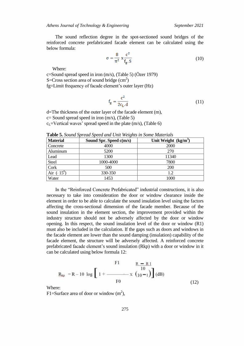
The sound reflection degree in the spot-sectioned sound bridges of the
reinforced concrete prefabricated facade element can be calculated using the
below formula:
(10)
Where:
c=Sound spread speed in iron (m/s), (Table 5) (Özer 1979)
S=Cross section area of sound bridge (cm2)
fg=Limit frequency of facade element‘s outer layer (Hz)
(11)
d=The thickness of the outer layer of the facade element (m),
c= Sound spread speed in iron (m/s), (Table 5)
cL=Vertical waves‘ spread speed in the plate (m/s), (Table 6)
Table 5. Sound Spread Speed and Unit Weights in Some Materials
Material Sound Spr. Speed c(m/s) Unit Weight (kg/m3)
Concrete 4000 2000
Aluminum 5200 270
Lead 1300 11340
Steel 1000-4000 7800
Cork 500 200
Air (˜ 150) 330-350 1.2
Water 1453 1000
In the ―Reinforced Concrete Prefabricated‖ industrial constructions, it is also
necessary to take into consideration the door or window clearance inside the
element in order to be able to calculate the sound insulation level using the factors
affecting the cross-sectional dimension of the facade member. Because of the
sound insulation in the element section, the improvement provided within the
industry structure should not be adversely affected by the door or window
opening. In this respect, the sound insulation level of the door or window (R1)
must also be included in the calculation. If the gaps such as doors and windows in
the facade element are lower than the sound damping (insulation) capability of the
facade element, the structure will be adversely affected. A reinforced concrete
prefabricated facade element‘s sound insulation (Rkp) with a door or window in it
can be calculated using below formula 12:
(12)
Where:
F1=Surface area of door or window (m2),

Vol. 8, No. 3 Tosun & Yasa: A Software Model for Parameters Affecting…
276
F0=Wall area including door or window (m2),
R=The B.A. Prefabricated facade element's sound damping (insulation) rate (dB),
R1=Sound damping (insulation) of door or window (dB) (Table 7)
Table 6. Constant Value of Some Building Materials (Özer 1979)
Material Bulk Density
(g/cm3)
Elasticity Module
(E=N/m2)
Vertical waves’
Spread speed in plate
High-dens. concrete 2.0....2.4 (25...35).105 3.4 . 10
3
Light concrete 0.6....1,3 (2.......4).105 1.7 . 10
3
Amiant Cement 2.0 28 . 105 3.7 . 10
3
Plaster 1.2 7 . 105 2.4 . 10
3
Brick (1.8....2.0) 16 . 105 (2.5....3) . 10
3
Lime Stuff 1.7 44.105 1.6 . 10
3
Glass 2.5 60.105 4.9 . 10
3
Flake boards 0.6....0.7 4,6 .105 2.7 . 10
3
Plexiglass 1.2 5.6.105 2.2 . 10
3
Glass Foam 0.13....1.6 (1.3....1.6).105 3.1 . 10
3
Aluminum 2.7 72 .105 5.2 . 10
3
Lead 11.3 17.105 1.3 . 10
3
Steel 7.8 210.105 5.1 . 10
3
Table 7. Sound Damping Rates of Windows (R) (Beranek and Ver 1992)
Window Type Avg. Sound Damping Rate ( R )
With elastic webbing Without elastic webbing
Simple Window ˜ 20 dB ≤ 25 dB
Double-Glazing ˜ 25 dB ≤ 30 dB
Double Casement ˜ 20 dB ≤ 40 dB
In double glass (layer) door and window formation, the g x a >100 formula
should be watched.
Where:
g=Layer area weight (kg/m2) (Table 4)
a=Distance between layers.
Example Solution with ―MT2 Prefabrike‖ Program
While the dimensional analysis of the ―reinforced concrete prefabricated‖
facade elements used in the industrial buildings‘ facades is done, another thing to
be considered in determining the section size is the sound insulation performance
of the element. When the sound performance of the element cross-section is
measured, some data must also be entered into the program. These are:
Outdoor Air Sound (dB): In order to be able to measure which facade element
is able to attenuate a high level sound, the outside air sound must be entered as
data in the ―Outside Air Sound (dB)‖ window of the program. These values are
shown in Table 4.

Athens Journal of Technology & Engineering September 2021
277
Frequency (fr): By measuring the frequency of the environment, the obtained
value must be added to the window of the ―frequency (fr)‖ in the program.
Working Hours of Industry Structure: It is necessary to decide which of the
activities in the industry structure will be carried out in the daytime or nighttime
environment and to check the options indicated in the program window. Because
the program will calculate the sound level for these two separate media separately
and will thus analyze them separately. The element cross-section will be sized in
such a way as to produce a suitable working environment inside against this
outside air noise.
Sound attenuation measure (Rpk) calculations of the facade element will be
done as such:
1. Night (22.00-06.00) Rpk<50 dB
2. Day (06.00-22.00) Rpk<60 dB
Only those sections that meet these conditions will give the appropriate analysis
report.
Door/Window: When the element cross-section is determined, there are a
number of factors that affect the outcome of the above analyses and should not be
overlooked in the program. These are the Door/Window gaps in the element. The
program offers options for these too. If there is a door/window opening in the front
element, the combination criteria in terms of the dimensions of the opening and the
sound technique of the doors and windows are also offered to the user as an
option.
The program makes all insulation calculations according to these preferences.
The facade element section can be verified until the sound insulation reaches the
appropriate values and the program can continue to feed back until proper
insulation is obtained.
By entering the above data, the program is then ready to perform sound
insulation analysis. If the data is changed for sound insulation analysis, the result
will change. If the outside air volume is high (140 dB) as in the above example,
the operation will start with the ―Analysis‖ command button and the dimensions of
this element will be ―Not suitable‖ in terms of the sound technique (Rpk) (Figure
15).
Analysis Results
This section is used to evaluate all of the previous study stages (Temperature,
Sizing, Static). It will display the precautions to be taken according to the results
obtained. If, as in the above example, the sound insulation performance of the
facade element is not sufficient and the message ―Not suitable‖ is received, then in
the Analysis Results section, the necessary precautions will be taken to take
precautions. Some precautions are:
The thickness of sound insulation material can be increased.
The door/window opening of the façade member may be reduced or
removed if possible.

Vol. 8, No. 3 Tosun & Yasa: A Software Model for Parameters Affecting…
278
Door/window joining technique options can be reviewed.
Frequency can be lowered.
The outdoor noise level can be reduced.
If all of this is inadequate, the process should be re-checked by adding a high-
sound-insulation material to the section of the ―Reinforced Concrete
Prefabricated‖ facade element. For this, the ―Heat‖, ―Size‖ and ―Static‖ analyzes
of the element are repeated until the sound analysis.
Figure 15. The Program’s “Not Suitable” Analysis Window
Sound Damping Rate/Frequency Graphic
After the sound insulation performance of the front element is made with the
―Analysis‖ command button, the Frequency (f=Hz) Graph will be drawn in the
program Sound Damping Rate (R=dB) based on the last found values of the
element. It will suffice to press the ―Graphic‖ command button for this. When the
―graphic‖ command button is pressed the program will prepare the graphic which
indicates the relation between ―Sound damping rate R(dB) and Frequency f (Hz)‖
(Figure 16). This graphic will come to the computer screen as a separate window
and will give the numerical values of the breakpoints. In other words, ―Sound
Damping Rate‖ (R=dB) can be tracked according to ―Frequency (fr)‖ changes.
The Graphic‘s ―Zoom‖ function can be used for detailed views. This procedure
will be completed with analyses and the user will be able to select ―Back‖, ―End‖,
―Close‖ or ―Print‖ command buttons to finish the process.

Athens Journal of Technology & Engineering September 2021
279
Figure 16. The Program’s “Graphic” Window for Sound Insulation
Conclusion
This model software is prepared for multi-layered and non-carrier reinforced
concrete. Prefabricated facade elements used in facades of Industrial Structures.
For this software, firstly the dimensional performance and behaviors expected
from the front elements were defined and the factors affecting them were
determined. Later, calculations on the factors affecting dimensions of facade
elements:
Thermal insulation
Coordination dimensions
Carrying properties (static)
Sound insulation feature can be made and optimum results can be obtained
by evaluating these calculations. The results can be displayed in the ―MT2
Prefabrike‖ analysis program in a virtual world window.
This model software will play an important role in giving product decisions
before production of facade element. These are:
1. The facade element will have the required ―Thermal Insulation‖ fittings for
application everywhere in Turkey.

Vol. 8, No. 3 Tosun & Yasa: A Software Model for Parameters Affecting…
280
2. According to the design form of the element on the facade, ―Coordination
Dimension‖ (A) will be calculated and it will facilitate the necessary
infrastructure preparations for the production of the element.
3. With optimization of the ―Element‘s Carrying Features‖ (static) risks of
breaks and cracks can be eliminated.
4. Industrial structures will have ―Sound Insulation‖ fittings to continue to
function well in noisy environments.
This ―MT2 Prefabricated‖ dimensional analysis program, developed for
―Reinforced Concrete. Prefabricated Facade Elements‖, is also a ―Model‖ in terms
of reducing diversity of dimensional behaviors expected from ―Reinforced
Concrete Prefabricated‖ structural members and facilitating ―Standardization‖
approaches.
With this software, it is aimed to bring a correct view to the problem of the
misunderstood standard concept of prefabricated building elements and is
exemplified on a model.
References
Azhar S (2011) Building Information Modeling (BIM): trends, benefits, risks, and
challenges for the AEC industry. American Society of Civil Engineers 11(3).
Azhar S, Nadeem A, Mok JYN, Leung BHY (2008) Building information modeling
(BIM): a new paradigm for visual interactive modeling and simulation for
construction projects. In Proceedings of the First International Conference on
Construction in Developing Countries, 435–446. Karachi, Pakistan.
Bakır E (1990) Design principles guide of prefabricated reinforced concrete buildings.
Ankara: Prefabricated Association.
Beranek LL, Ver, IL (1992) Noise and vibration control engineering. In Principle and
Aplications. USA.
Cansun O (1989) Curtain wall. Lecture Notes. İstanbul: Department of Building, İ.T.Ü.
Faculty of Architecture.
Christiane MH, Davide L, Isaac G (2018) Parametric design of sculptural fibre reinforced
concrete facade components: learning, adapting and prototyping. In Proceedings of
the 23rd International Conference of the Association for Computer-Aided
Architectural Design Research in Asia (CAADRIA) 2018, volume 2, 319–328.
Chudley R (1994) Construction technology. Second Edition. Pearson India.
Eastman C, Teicholz P, Sacks R, Liston K (2008) BIM handbook: a guide to building
information modeling for owners, managers, designers, engineers and contractors.
New York: Wiley.
Eriç M (1994) Building physics and materials. Istanbul: Literature Publications 2.
Escrig F, Brebbia CA (1996) Mobile rapidly assembled structure-II. Southampton:
Bookcraft Limited.
International Standardization Organization – ISO (1990) Accoustics - Determination of
occupational noise exposure and estimation of noise-induced hearing impairment.
ISO 1999.2. Geneva, Switzerland.
Lantim D (1998) Delphi 3. Computer Software. Paris: Eyrolles.
Montali J, Overend M, Pelken PM, Sauchelli M (2017) Knowledge-based engineering
applications for supporting the design of precast concrete facade panels. In DS 87-6

Athens Journal of Technology & Engineering September 2021
281
Proceedings of the 21st International Conference on Engineering Design (ICED 17),
volume 6, 131–139. Vancouver, Canada.
Özer M (1979) Building acoustics and sound insulation. Istanbul: Arpaz Publishing.
Şener H (1990) Open Systems in Industrialized Building. Architecture Print Workshop.
Istanbul: İ.T.Ü. Faculty of Architecture.
TSE 825 (1999) Thermal insulation requirements for buildings. Ankara: T.C. Bayındırlık
ve İskan Bakanlığı.
Wang-Dong Y, Qiang C, Ni L (2011) A framework-based model of software construction.
In IEEE 2nd International Conference on Software Engineering and Service Science,
DOI=10.1109/ICSESS.2011.5982310.
Young RW (1988) Optimum levels for reporting community noise. Washington, USA:
Private Communication.

Vol. 8, No. 3 Tosun & Yasa: A Software Model for Parameters Affecting…
282