Embed Size (px)
Citation preview
A Software-Defined Receiver Architecture forCellular CDMA-Based Navigation
Joe Khalife, Kimia Shamaei, and Zaher M. KassasDepartment of Electrical and Computer Engineering
University of California, Riverside{[email protected], [email protected], [email protected]}
Abstract—A detailed software-defined receiver (SDR) architec-ture for navigation using cellular code division multiple access(CDMA) signals is presented. The cellular forward-link signalstructure is described and models for the transmitted andreceived signals are developed. Particular attention is paid torelevant information that could be extracted and subsequentlyexploited for navigation and timing purposes. The differencesbetween a typical GPS receiver and the proposed cellular CDMAreceiver are highlighted. Moreover, a framework that is based ona mapping/navigating receiver scheme for navigation in a cellularCDMA environment is studied. The position and timing errorsarising due to estimating the base transceiver station clock biasesin different cell sectors are also analyzed. Experimental resultsutilizing the proposed SDR are presented demonstrating a meandistance difference of 5.51 m from a GPS navigation solution.
Index Terms—Navigation, signals of opportunity, cellularCDMA, software-defined radio.
I. I NTRODUCTION
Over the past decade, research in navigation via signals ofopportunity (SOPs) has revealed their potential as an alter-native or a complement to global navigation satellite systemGNSS) [1], [2]. Such signals include AM/FM radio signals [3],[4], iridium satellite signals [5], [6], cellular signals [7], [8],digital television signals [9], [10], and Wi-Fi signals [11], [12].The literature on SOP-based navigation answers theoreticalquestions on the observability and estimability of the signallandscape map for a different number of receivers, a differentnumber of SOPs, and variousa priori knowledge scenarios[13], [14]. Moreover, experimental results have demonstratedreceiver localization and timing via SOPs [2], [8], [15].
There are two main challenges associated with using SOPsfor navigation: (1) the unavailability of appropriate precise,low-level signal models for optimal extraction of states andparameters of interest for navigation and timing purposes and(2) the absence of published receiver architectures capable ofproducing navigation observables. This paper addresses thesetwo challenges for cellular CDMA signals. These signals areabundant, are transmitted at high power, and have a structurethat is similar to the well-understood GPS signals, whichrenders them good candidates for navigation. To the authors’knowledge, while previous work demonstrated experimentalresults for navigation via cellular CDMA signals, neither ofthese two challenges has been fully addressed.
Unlike GNSS, the states of a cellular CDMA basetransceiver station (BTS) are unknown to a navigating receiver
and need to be estimated. Although, the IS-95 standard statesthat a CDMA BTS should transmit its position, local wirelessproviders do not usually transmit such information [16], [17].Hence, the position of the BTSs need to be manually surveyedor estimated on-the-fly individually or collaboratively [18],[19]. Nevertheless, while the position states of a BTS arestatic, the clock error states of the BTS are dynamic andneed to be continuously estimated via (1) a mapping receiver,which shares such estimates with the navigating receiver or(2)by the navigating receiver itself by adopting a simultaneouslocalization and mapping approach [20], [21], [22].
Whether it is for navigation or mapping purposes, a spe-cialized receiver is needed to process the received cellularCDMA signal and extract relevant positioning and timingobservables. Cellular CDMA receivers are routinely imple-mented in hardware in mobile phones; however, hardwareimplementations limits the ability to extract or modify infor-mation within the receiver. As such, software-defined radio(SDR) becomes an attractive platform of choice for imple-menting a cellular CDMA receiver for navigation purposes,because of its inherent advantages: (1) flexibility: designs arehardware independent, (2) modularity: different functions canbe implemented independently, and (3) upgradability: minimalchanges are needed to improve designs. Although most SDRsused to be limited to post-processing applications, processor-specific optimization techniques allow for real-time operation[23]. Consequently, SDR implementations are becoming moreprevalent. Moreover, graphical programming languages suchas LabVIEW and Simulink offer the advantage of a one-to-onecorrespondence between the architectural conceptualization ofthe SDR and software implementation [24].
This paper makes two contributions. First, it presents adetailed and reproducible navigation cellular CDMA SDRarchitecture along with precise, low-level signal models for op-timal extraction of relevant navigation and timing informationfrom received signals. Second, the paper studies a navigationframework in which a mapping receiver estimates the statesof BTSs and shares such estimates with a navigating receiver,which navigates exclusively with cellular CDMA signals. Thepaper analyzes the induced error in the navigation solutiondue to having the mapping and navigating receivers listeningto different sectors within a BTS cell. The paper also presentsexperimental results comparing the trajectories correspondingto a navigation solution from GPS and that of the proposed
cellular CDMA SDR. The mean distance difference betweenthe trajectories is shown to be 5.51 m with a standard deviationof 4.01 m and a maximum difference of 11.11 m.
The remainder of the paper is organized as follows. SectionII provides an overview of the cellular CDMA forward linksignal structure. Section III presents a complete LabVIEW-based implementation of the navigation cellular CDMA SDR.Section IV analyzes a mapping/navigating receiver frameworkfor navigation with celluar CDMA signals. Experimental re-sults are given in Section V and concluding remarks arediscussed in Section VI.
II. CELLULAR CDMA FORWARD L INK SIGNAL
STRUCTURE
In a cellular CDMA communication system, 64 logicalchannels are multiplexed on the forward link channel: a pilotchannel, a sync channel, 7 paging channels and 55 trafficchannels [25]. In the following subsection, the modulationprocess of the forward link channel is presented. Next, abrief overview of the pilot, sync, and paging channels, fromwhich timing and positioning information can be extracted,is provided. Finally, models of the transmitted and receivedsignals are given.
A. Modulation of Forward Link CDMA Signals
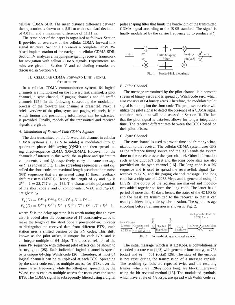
The data transmitted on the forward link channel in cellularCDMA systems (i.e., BTS to mbile) is modulated throughquadrature phase shift keying (QPSK) and then spread us-ing direct-sequence CDMA (DS-CDMA). However, for thechannels of interest in this work, the in-phase and quadraturecomponents,I andQ, respectively, carry the same messagem(t) as shown in Fig. 1. The spreading sequencescI andcQ,called the short code, are maximal-length pseudorandom noise(PN) sequences that are generated using 15 linear feedbackshift registers (LFSRs). Hence, the length ofcI and cQ is215 − 1 = 32, 767 chips [16]. The characteristic polynomialsof the short codeI andQ components,PI(D) andPQ(D),are given by
PI(D) = D15+D13+D9+D8+D7+D5+1
PQ(D) = D15+D12+D11+D10+D6+D5+D4+D3+1,
whereD is the delay operator. It is worth noting that an extrazero is added after the occurrence of 14 consecutive zeros tomake the length of the short code a power-of-two. In orderto distinguish the received data from different BTSs, eachstation uses a shifted version of the PN codes. This shift,known as the pilot offset, is unique for each BTS and isan integer multiple of 64 chips. The cross-correlation of thesame PN sequence with different pilot offsets can be shown tobe negligible [25]. Each individual logical channel is spreadby a unique 64-chip Walsh code [26]. Therefore, at most 64logical channels can be multiplexed at each BTS. Spreadingby the short code enables multiple access for BTSs over thesame carrier frequency, while the orthogonal spreading by theWlash codes enables multiple access for users over the sameBTS. The CDMA signal is subsequently filtered using a digital
pulse shaping filter that limits the bandwidth of the transmittedCDMA signal according to the IS-95 standard. The signal isfinally modulated by the carrier frequencyωc to produces(t).
cI
cQ
cos(ωct)
sin(ωct)
s(t)m(t)
FilterPulse-Shaping
Fig. 1. Forward-link modulator.
B. Pilot Channel
The message transmitted by the pilot channel is a constantstream of binary zeros and is spread by Walsh code zero, whichalso consists of 64 binary zeros. Therefore, the modulated pilotsignal is nothing but the short code. The proposed receiver willutilize the pilot signal to detect the presence of a CDMA signaland then track it, as will be discussed in Section III. The factthat the pilot signal is data-less allows for longer integrationtime. The receiver differentiates between the BTSs based ontheir pilot offsets.
C. Sync Channel
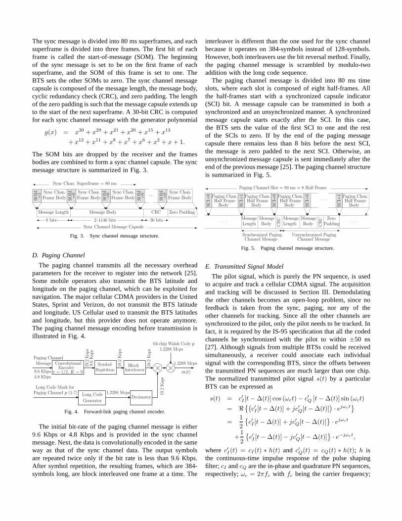
The sync channel is used to provide time and frame synchro-nization to the receiver. The cellular CDMA system uses GPSas the reference timing source and the BTS sends the systemtime to the receiver over the sync channel. Other informationsuch as the pilot PN offset and the long code state are alsoprovided on the sync channel [16]. The long code is a PNsequence and is used to spread the reverse-link signal (i.e.,receiver to BTS) and the paging channel message. The longcode has a chip rate of 1.2288 Mcps and is generated using 42LFSRs. The output of the registers are masked and modulo-two added together to form the long code. The latter has aperiod of more than 41 days; hence, the states of the 42 LFSRsand the mask are transmitted to the receiver so that it canreadily achieve long code synchronization. The sync messageencoding before transmission is shown in Fig. 2.
ConvolutionalEncoder
SymbolRepitition
BlockInterleaver
Sync ChannelMessage 4.8 Ksps 1.2288 Mcps
64-chip Walsh Code 321.2288 Mcps
m(t)r = 1/2, K = 91.2 Kbps
2.4Ksps
4.8Ksps
Fig. 2. Forward-link sync channel encoder.
The initial message, which is at 1.2 Kbps, is convolutionallyencoded at a rater = (1/2) with generator functionsg0 = 753(octal) andg1 = 561 (octal) [26]. The state of the encoderis not reset during the transmission of a message capsule.The resulting symbols are repeated twice and the resultingframes, which are 128-symbols long, are block interleavedusing the bit reversal method [16]. The modulated symbols,which have a rate of 4.8 Ksps, are spread with Walsh code 32.
The sync message is divided into 80 ms superframes, and eachsuperframe is divided into three frames. The first bit of eachframe is called the start-of-message (SOM). The beginningof the sync message is set to be on the first frame of eachsuperframe, and the SOM of this frame is set to one. TheBTS sets the other SOMs to zero. The sync channel messagecapsule is composed of the message length, the message body,cyclic redundancy check (CRC), and zero padding. The lengthof the zero padding is such that the message capsule extends upto the start of the next superframe. A 30-bit CRC is computedfor each sync channel message with the generator polynomial
g(x) = x30 + x29 + x21 + x20 + x15 + x13
+ x12 + x11 + x8 + x7 + x6 + x2 + x+ 1.
The SOM bits are dropped by the receiver and the framesbodies are combined to form a sync channel capsule. The syncmessage structure is summarized in Fig. 3.
Sync Chan. Superframe = 80 ms
Sync Chan.
Frame BodySOM
Message Length Message Body Zero PaddingCRC
Sync Channel Message Capsule
8 bits 2–1146 bits 30 bits
=1 ...
Sync Chan.
Frame BodySOM
=0 Sync Chan.
Frame BodySOM
=0 Sync Chan.
Frame BodySOM
=0
SOM
=0
Fig. 3. Sync channel message structure.
D. Paging Channel
The paging channel transmits all the necessary overheadparameters for the receiver to register into the network [25].Some mobile operators also transmit the BTS latitude andlongitude on the paging channel, which can be exploited fornavigation. The major cellular CDMA providers in the UnitedStates, Sprint and Verizon, do not transmit the BTS latitudeand longitude. US Cellular used to transmit the BTS latitudesand longitude, but this provider does not operate anymore.The paging channel message encoding before transmission isillustrated in Fig. 4.
ConvolutionalEncoder
SymbolRepitition
BlockInterleaver
Paging ChannelMessage
19.2
Ksps
1.2288 Mcps
64-chip Walsh Code p1.2288 Mcps
m(t)
Long Code
GeneratorDecimator
Long Code Mask forPaging Channel p (1-7) 1.2288 Mcps
r = 1/2, K = 99.6 Kbps4.8 Kbps
9.6Ksps
19.2
Ksps
19.2
Ksps
19.2
Ksps
Fig. 4. Forward-link paging channel encoder.
The initial bit-rate of the paging channel message is either9.6 Kbps or 4.8 Kbps and is provided in the sync channelmessage. Next, the data is convolutionally encoded in the sameway as that of the sync channel data. The output symbolsare repeated twice only if the bit rate is less than 9.6 Kbps.After symbol repetition, the resulting frames, which are 384-symbols long, are block interleaved one frame at a time. The
interleaver is different than the one used for the sync channelbecause it operates on 384-symbols instead of 128-symbols.However, both interleavers use the bit reversal method. Finally,the paging channel message is scrambled by modulo-twoaddition with the long code sequence.
The paging channel message is divided into 80 ms timeslots, where each slot is composed of eight half-frames. Allthe half-frames start with a synchronized capsule indicator(SCI) bit. A message capsule can be transmitted in both asynchronized and an unsynchronized manner. A synchronizedmessage capsule starts exactly after the SCI. In this case,the BTS sets the value of the first SCI to one and the restof the SCIs to zero. If by the end of the paging messagecapsule there remains less than 8 bits before the next SCI,the message is zero padded to the next SCI. Otherwise, anunsynchronized message capsule is sent immediately after theend of the previous message [25]. The paging channel structureis summarized in Fig. 5.
Paging Channel Slot = 80 ms = 8 Half Frame
Message
Synchronized PagingChannel Message
Length
Message
Body
Message
Length
Message
Body
Unsynchronized PagingChannel Message
. . .. . .
Paging Chan.Half Frame
SCI=
0Body
Paging Chan.Half Frame
SCI=
1
Body
Paging Chan.Half Frame
SCI=
0
Body
Paging Chan.Half Frame
SCI=
1
Body
. . .
CRC
CRC Zero
Padding
SCI=
0
Fig. 5. Paging channel message structure.
E. Transmitted Signal Model
The pilot signal, which is purely the PN sequence, is usedto acquire and track a cellular CDMA signal. The acquisitionand tracking will be discussed in Section III. Demodulatingthe other channels becomes an open-loop problem, since nofeedback is taken from the sync, paging, nor any of theother channels for tracking. Since all the other channels aresynchronized to the pilot, only the pilot needs to be tracked. Infact, it is required by the IS-95 specification that all the codedchannels be synchronized with the pilot to within±50 ns[27]. Although signals from multiple BTSs could be receivedsimultaneously, a receiver could associate each individualsignal with the corresponding BTS, since the offsets betweenthe transmitted PN sequences are much larger than one chip.The normalized transmitted pilot signals(t) by a particularBTS can be expressed as
s(t) = c′I [t−∆(t)] cos (ωct)− c′Q [t−∆(t)] sin (ωct)
= ℜ{(
c′I [t−∆(t)] + jc′Q[t−∆(t)])
· ejωct}
=1
2
{
c′I [t−∆(t)] + jc′Q[t−∆(t)]}
· ejωct
+1
2
{
c′I [t−∆(t)]− jc′Q[t−∆(t)]}
· e−jωct,
where c′I(t) = cI(t) ∗ h(t) and c′Q(t) = cQ(t) ∗ h(t); h isthe continuous-time impulse response of the pulse shapingfilter; cI andcQ are the in-phase and quadrature PN sequences,respectively;ωc = 2πfc with fc being the carrier frequency;
and∆ is the absolute clock bias of the BTS from GPS time.The total clock bias∆ is defined as
∆(t) = 64 · (PNoffsetTc) + δts(t),
wherePNoffset is the PN offset of the BTS,Tc = 1×10⁻⁶
1.2288 sis the chip interval, andδts is the BTS clock bias. Since thechip interval is known and the PN offset can be decoded bythe receiver, onlyδts needs to be estimated. It is worth notingthat the cdma2000 standard requires the BTS’s clock to besynchronized with GPS to within 10µs, which translates to arange of approximately 3 km (the average cell size) [27]. Thisrequirement is enough to prevent severe interference betweenthe short codes transmitted from different BTSs and maintainsthe CDMA system’s capability to perform soft hand-offs [16].The clock bias of the BTS can therefore be neglected forcommunication purposes. However, ignoringδts in navigationapplications can be disastrous, and it is therefore crucialforthe receiver to know the BTS’s clock bias. Estimation ofδtsis discussed in Section IV.
F. Received Signal Model After Front-End Processing
Assuming the transmitted signal to have propagated throughan additive white Gaussian noise channel, a model of thereceived discrete-time signalr[k] after radio frequency (RF)front-end processing: downmixing, a quadrature approach tobandpass sampling [28], and quantization can be expressed as
r[k]=1
2
{
c′I [tk−ts(tk)]−jc′Q[tk−ts(tk)]}
·ejθ(tk)+n[k], (1)
wherets(tk) , δtTOF +∆(tk−δtTOF ) is the PN code phaseof the BTS,tk = kTs is the sample time expressed in receivertime, Ts is the sampling period,δtTOF is the time-of-flight(TOF) from the BTS to the receiver,θ(tk) is the beat carrierphase of the received signal, andn[k] = nI [k] + jnQ[k] withnI [k] and nQ[k] being independent, identically-distributed(i.i.d.) Gaussian random sequences with zero-mean and vari-anceσ2
n. The receiver developed in Section III will operate onthe samples ofr[k] in (1).
III. C ELLULAR CDMA RECEIVER ARCHITECTURE
The cellular CDMA receiver consists of three main stages:signal acquisition, tracking, and decoding. The first subsectiongives a brief description of the correlation process in thecellular CDMA navigation receiver. The following subsectionspresent a detailed software implementation of the three re-ceiver stages. The main differences between a GPS receiverand the developed cellular CDMA receiver are highlighted.
A. Cellular CDMA Receiver Correlator
Given samples of the baseband signal exiting the RF front-end, defined in (1), the cellular CDMA receiver first wipes-offthe residual carrier phase and match-filters the resulting signal.The output of the matched-filter can be expressed as
x[k] =[
r[k] · e−jθ(tk)]
∗ h[−k], (2)
where θ is the beat carrier phase estimate andh[k] is apulse shaping filter, which is a discrete-time version of theone used to shape the spectrum of the transmitted signal,with a finite-impulse response specified in [16]. Next,x[k] iscorrelated with a local replica of the spreading PN sequence.The resulting correlation is used as a measure of the qualityof the code phase and the beat carrier phase estimates. In adigital receiver, the correlation operation is expressed as
Si =
i+Ns−1∑
k=i
x[k]{
cI [tk − ts(tk)] + jcQ[tk − ts(tk)]}
, (3)
whereSi is the ith subaccumulation,Ns is the number ofsamples per subaccumulation, andts(tk) is the code starttime estimate over theith subaccumulation. The code phasecan be assumed to be approximately constant over a shortsubaccumulation intervalTsub; hence, ts(tk) ≈ tsi . It isworth mentioning thatTsub can be made arbitrarily large,theoretically, since no data is transmitted on the pilot channel.Practically,Tsub is mainly limited by the stability of the BTSand receiver oscillators [29]. In this paper,Tsub is set to onePN code period. The carrier phase estimate is modeled asθ(tk) = 2πfDi
tk + θ0, where fDiis the apparent Doppler
frequency estimate over theith subaccumulation, andθ0 isthe initial beat carrier phase of the received signal. As in aGPS receiver, the value ofθ0 is set to zero in the acquisitionstage and is subsequently maintained in the tracking stage.Theapparent Doppler frequency is assumed to be constant over ashortTsub. Substituting forr[k] andx[k], defined in (1)-(2),into (3), it can be shown that
Si = NsRc(∆ti)
[
i+Ns−1∑
k=i
ej∆θ(tk)
]
+ ni, (4)
whereRc is the autocorrelation function of the PN sequencescI andcQ, ∆ti , tsi − tsi is the code phase error,∆θ(tk) ,θ(tk)− θ(tk) is the carrier phase error, andni , nIi + jnQi
with nIi and nQibeing i.i.d. Gaussian random sequences
with zero-mean and varianceNsσ2n. The expression ofSi
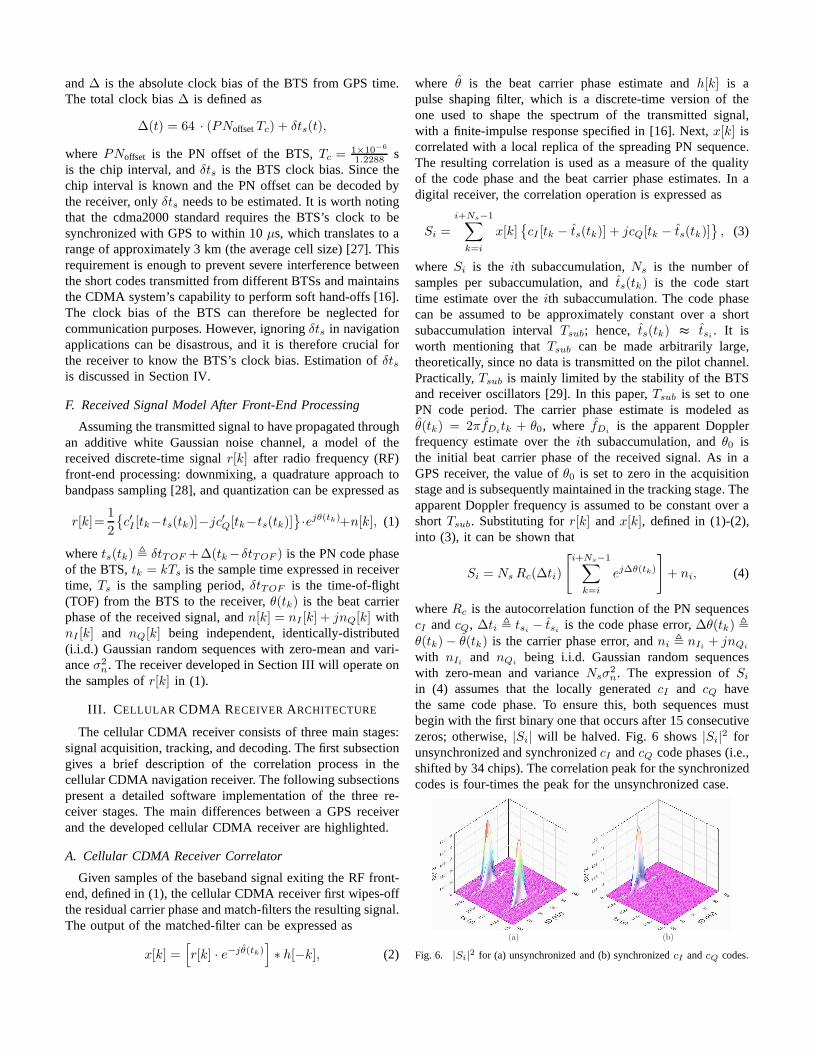
in (4) assumes that the locally generatedcI and cQ havethe same code phase. To ensure this, both sequences mustbegin with the first binary one that occurs after 15 consecutivezeros; otherwise,|Si| will be halved. Fig. 6 shows|Si|2 forunsynchronized and synchronizedcI andcQ code phases (i.e.,shifted by 34 chips). The correlation peak for the synchronizedcodes is four-times the peak for the unsynchronized case.
(a) (b)
Fig. 6. |Si|2 for (a) unsynchronized and (b) synchronizedcI andcQ codes.
The carrier wipe-off and correlation stages are illustrated inFig. 7.
cI [tk − tsi] + jcQ[tk − tsi]e−jθ(tk)Pulse-Shaping
r[k] Si
Carrier wipe-off Correlator
Filter
k = i
i+Ns − 1
(·)∑
Fig. 7. Carrier wipe-off and correlator diagram. Thick lines indicate acomplex-valued variable.
B. Acquisition
The objective of this stage is to determine which BTSs arein the receiver’s proximity and to obtain a coarse estimate oftheir corresponding code start times and Doppler frequencies.For a particular PN offset, a search over the code start timeand Doppler frequency is performed to detect the presence ofa signal. To determine the range of Doppler frequencies tosearch over, one must consider the relative motion betweenthe receiver and the BTS and the stability of the receiver’soscillator. For instance, a Doppler shift of 122 Hz will beobserved for a cellular CDMA carrier frequency of 822.75MHz at a mobile receiver with a receiver-to-BTS line-of-sight velocity of 150 km/h. Furthermore, a Doppler shift upto 250 Hz was experimentally observed for a stationary re-ceiver equipped with a poor temperature-compensated crystaloscillator (TCXO). Therefore, the Doppler frequency searchwindow is chosen to be between -500 and 500 Hz at a carrierfrequency of 882.75 MHz. The frequency spacing∆fD mustbe a fraction of1/Tsub, which implies that∆fD ≪ 37.5 Hz,if Tsub is assumed to be one PN code period. In this paper,∆fD is chosen to be between 8 and 12 Hz. The code starttime search window is naturally chosen to be one PN codeinterval with a delay spacing of one sample.
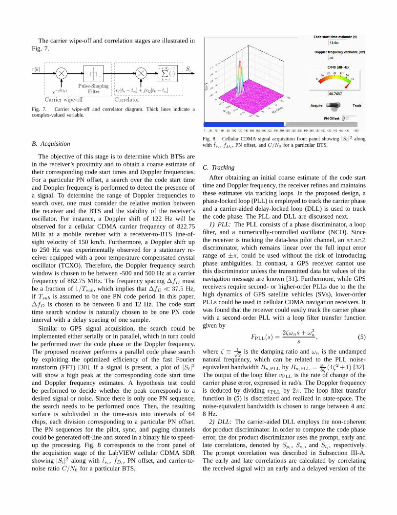
Similar to GPS signal acquisition, the search could beimplemented either serially or in parallel, which in turn couldbe performed over the code phase or the Doppler frequency.The proposed receiver performs a parallel code phase searchby exploiting the optimized efficiency of the fast Fouriertransform (FFT) [30]. If a signal is present, a plot of|Si|2will show a high peak at the corresponding code start timeand Doppler frequency estimates. A hypothesis test couldbe performed to decide whether the peak corresponds to adesired signal or noise. Since there is only one PN sequence,the search needs to be performed once. Then, the resultingsurface is subdivided in the time-axis into intervals of 64chips, each division corresponding to a particular PN offset.The PN sequences for the pilot, sync, and paging channelscould be generated off-line and stored in a binary file to speed-up the processing. Fig. 8 corresponds to the front panel ofthe acquisition stage of the LabVIEW cellular CDMA SDRshowing |Si|2 along with tsi , fDi
, PN offset, and carrier-to-noise ratioC/N0 for a particular BTS.
Fig. 8. Cellular CDMA signal acquisition front panel showing |Si|2 along
with tsi , fDi, PN offset, andC/N0 for a particular BTS.
C. Tracking
After obtaining an initial coarse estimate of the code starttime and Doppler frequency, the receiver refines and maintainsthese estimates via tracking loops. In the proposed design,aphase-locked loop (PLL) is employed to track the carrier phaseand a carrier-aided delay-locked loop (DLL) is used to trackthe code phase. The PLL and DLL are discussed next.
1) PLL: The PLL consists of a phase discriminator, a loopfilter, and a numerically-controlled oscillator (NCO). Sincethe receiver is tracking the data-less pilot channel, anatan2discriminator, which remains linear over the full input errorrange of±π, could be used without the risk of introducingphase ambiguities. In contrast, a GPS receiver cannot usethis discriminator unless the transmitted data bit values of thenavigation message are known [31]. Furthermore, while GPSreceivers require second- or higher-order PLLs due to the thehigh dynamics of GPS satellite vehicles (SVs), lower-orderPLLs could be used in cellular CDMA navigation receivers. Itwas found that the receiver could easily track the carrier phasewith a second-order PLL with a loop filter transfer functiongiven by
FPLL(s) =2ζωns+ ω2
n
s, (5)
whereζ ≡ 1√2
is the damping ratio andωn is the undampednatural frequency, which can be related to the PLL noise-equivalent bandwidthBn,PLL by Bn,PLL = ωn
8ζ (4ζ2+1) [32].
The output of the loop filtervPLL is the rate of change of thecarrier phase error, expressed in rad/s. The Doppler frequencyis deduced by dividingvPLL by 2π. The loop filter transferfunction in (5) is discretized and realized in state-space.Thenoise-equivalent bandwidth is chosen to range between 4 and8 Hz.
2) DLL: The carrier-aided DLL employs the non-coherentdot product discriminator. In order to compute the code phaseerror, the dot product discriminator uses the prompt, earlyandlate correlations, denoted bySpi , Sei , andSli , respectively.The prompt correlation was described in Subsection III-A.The early and late correlations are calculated by correlatingthe received signal with an early and a delayed version of the
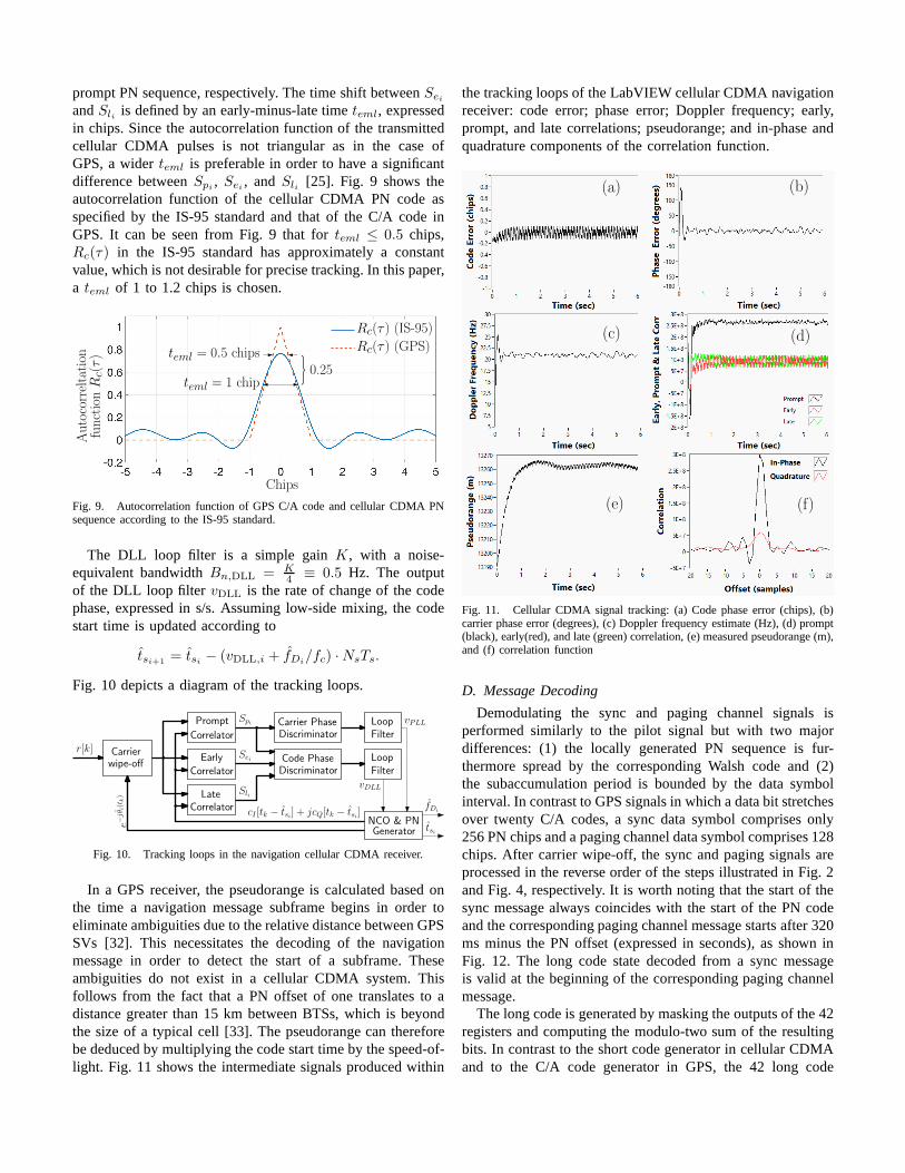
prompt PN sequence, respectively. The time shift betweenSeiandSli is defined by an early-minus-late timeteml, expressedin chips. Since the autocorrelation function of the transmittedcellular CDMA pulses is not triangular as in the case ofGPS, a widerteml is preferable in order to have a significantdifference betweenSpi , Sei , andSli [25]. Fig. 9 shows theautocorrelation function of the cellular CDMA PN code asspecified by the IS-95 standard and that of the C/A code inGPS. It can be seen from Fig. 9 that forteml ≤ 0.5 chips,Rc(τ) in the IS-95 standard has approximately a constantvalue, which is not desirable for precise tracking. In this paper,a teml of 1 to 1.2 chips is chosen.
Chips
Autocorreltation
Rc(τ ) (IS-95)
Rc(τ ) (GPS)teml = 0.5 chips
{0.25teml = 1 chip
functionRc(τ)
Fig. 9. Autocorrelation function of GPS C/A code and cellular CDMA PNsequence according to the IS-95 standard.
The DLL loop filter is a simple gainK, with a noise-equivalent bandwidthBn,DLL = K
4 ≡ 0.5 Hz. The outputof the DLL loop filter vDLL is the rate of change of the codephase, expressed in s/s. Assuming low-side mixing, the codestart time is updated according to
tsi+1 = tsi − (vDLL,i + fDi/fc) ·NsTs.
Fig. 10 depicts a diagram of the tracking loops.
r[k] Carrierwipe-off
Correlator
Loop
Filter
Loop
FilterCarrier PhaseDiscriminator
Spi
Sli
Sei
NCO & PNGenerator
Late
Early
Prompt
fDi
tsi
cI [tk − tsi] + jcQ[tk − tsi]
e−jθi(t
k)
Correlator
Correlator
Code PhaseDiscriminator
vDLL
vPLL
Fig. 10. Tracking loops in the navigation cellular CDMA receiver.
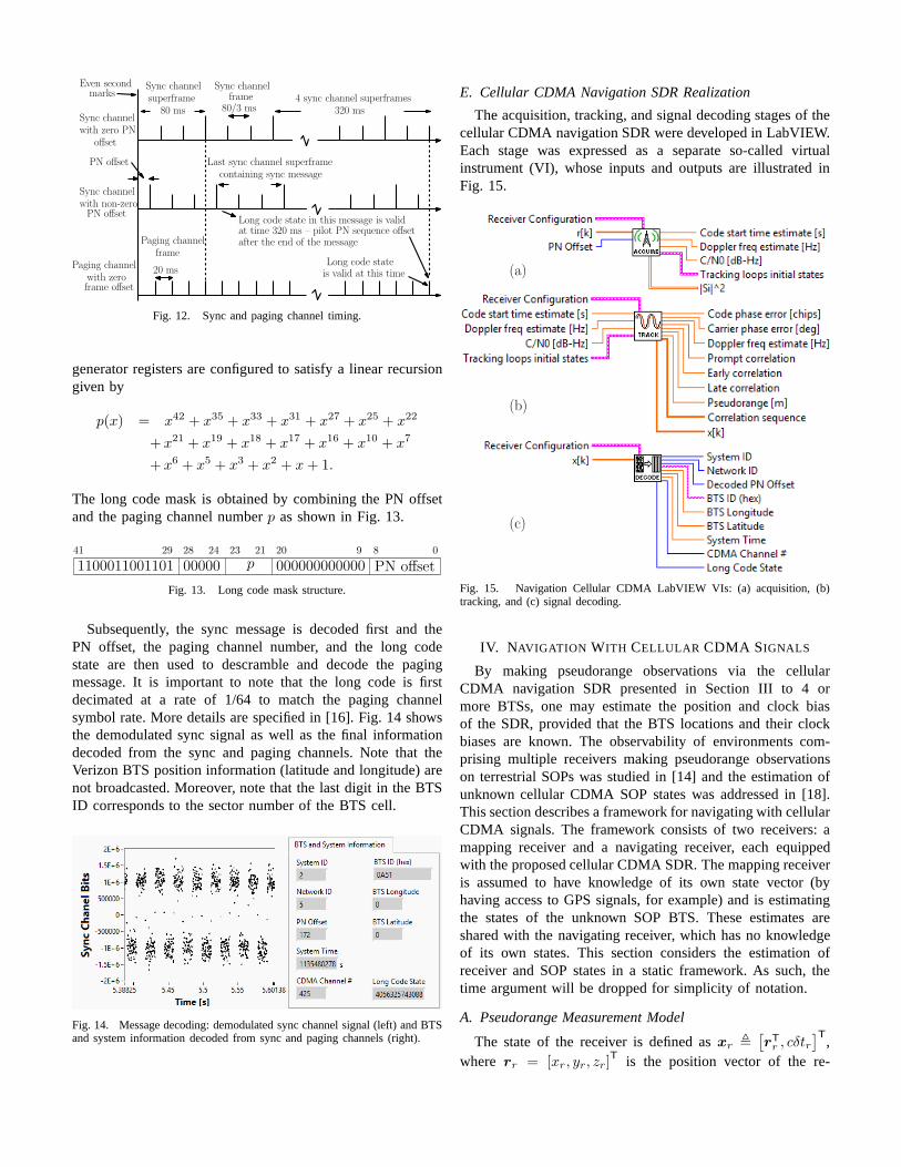
In a GPS receiver, the pseudorange is calculated based onthe time a navigation message subframe begins in order toeliminate ambiguities due to the relative distance betweenGPSSVs [32]. This necessitates the decoding of the navigationmessage in order to detect the start of a subframe. Theseambiguities do not exist in a cellular CDMA system. Thisfollows from the fact that a PN offset of one translates to adistance greater than 15 km between BTSs, which is beyondthe size of a typical cell [33]. The pseudorange can thereforebe deduced by multiplying the code start time by the speed-of-light. Fig. 11 shows the intermediate signals produced within
the tracking loops of the LabVIEW cellular CDMA navigationreceiver: code error; phase error; Doppler frequency; early,prompt, and late correlations; pseudorange; and in-phase andquadrature components of the correlation function.
(a) (b)
(c) (d)
(e) (f)
Fig. 11. Cellular CDMA signal tracking: (a) Code phase error(chips), (b)carrier phase error (degrees), (c) Doppler frequency estimate (Hz), (d) prompt(black), early(red), and late (green) correlation, (e) measured pseudorange (m),and (f) correlation function
D. Message Decoding
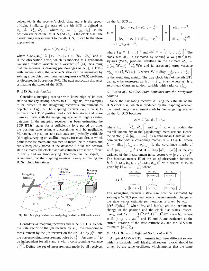
Demodulating the sync and paging channel signals isperformed similarly to the pilot signal but with two majordifferences: (1) the locally generated PN sequence is fur-thermore spread by the corresponding Walsh code and (2)the subaccumulation period is bounded by the data symbolinterval. In contrast to GPS signals in which a data bit stretchesover twenty C/A codes, a sync data symbol comprises only256 PN chips and a paging channel data symbol comprises 128chips. After carrier wipe-off, the sync and paging signals areprocessed in the reverse order of the steps illustrated in Fig. 2and Fig. 4, respectively. It is worth noting that the start ofthesync message always coincides with the start of the PN codeand the corresponding paging channel message starts after 320ms minus the PN offset (expressed in seconds), as shown inFig. 12. The long code state decoded from a sync messageis valid at the beginning of the corresponding paging channelmessage.
The long code is generated by masking the outputs of the 42registers and computing the modulo-two sum of the resultingbits. In contrast to the short code generator in cellular CDMAand to the C/A code generator in GPS, the 42 long code
Even secondmarks
Sync channelwith zero PN
offset
Sync channelsuperframe
80 ms
Sync channelframe
80/3 ms4 sync channel superframes
320 ms
Sync channelwith non-zeroPN offset
PN offset Last sync channel superframecontaining sync message
Long code state in this message is validat time 320 ms – pilot PN sequence offsetafter the end of the message
Paging channelwith zeroframe offset
Paging channelframe
20 msLong code stateis valid at this time
Fig. 12. Sync and paging channel timing.
generator registers are configured to satisfy a linear recursiongiven by
p(x) = x42 + x35 + x33 + x31 + x27 + x25 + x22
+ x21 + x19 + x18 + x17 + x16 + x10 + x7
+ x6 + x5 + x3 + x2 + x+ 1.
The long code mask is obtained by combining the PN offsetand the paging channel numberp as shown in Fig. 13.
1100011001101 00000 000000000000 PN offsetp
41 29 28 24 21 20 9 8 023
Fig. 13. Long code mask structure.
Subsequently, the sync message is decoded first and thePN offset, the paging channel number, and the long codestate are then used to descramble and decode the pagingmessage. It is important to note that the long code is firstdecimated at a rate of 1/64 to match the paging channelsymbol rate. More details are specified in [16]. Fig. 14 showsthe demodulated sync signal as well as the final informationdecoded from the sync and paging channels. Note that theVerizon BTS position information (latitude and longitude)arenot broadcasted. Moreover, note that the last digit in the BTSID corresponds to the sector number of the BTS cell.
Fig. 14. Message decoding: demodulated sync channel signal(left) and BTSand system information decoded from sync and paging channels (right).
E. Cellular CDMA Navigation SDR Realization
The acquisition, tracking, and signal decoding stages of thecellular CDMA navigation SDR were developed in LabVIEW.Each stage was expressed as a separate so-called virtualinstrument (VI), whose inputs and outputs are illustrated inFig. 15.
(b)
(c)
(a)
Fig. 15. Navigation Cellular CDMA LabVIEW VIs: (a) acquisition, (b)tracking, and (c) signal decoding.
IV. NAVIGATION WITH CELLULAR CDMA SIGNALS
By making pseudorange observations via the cellularCDMA navigation SDR presented in Section III to 4 ormore BTSs, one may estimate the position and clock biasof the SDR, provided that the BTS locations and their clockbiases are known. The observability of environments com-prising multiple receivers making pseudorange observationson terrestrial SOPs was studied in [14] and the estimation ofunknown cellular CDMA SOP states was addressed in [18].This section describes a framework for navigating with cellularCDMA signals. The framework consists of two receivers: amapping receiver and a navigating receiver, each equippedwith the proposed cellular CDMA SDR. The mapping receiveris assumed to have knowledge of its own state vector (byhaving access to GPS signals, for example) and is estimatingthe states of the unknown SOP BTS. These estimates areshared with the navigating receiver, which has no knowledgeof its own states. This section considers the estimation ofreceiver and SOP states in a static framework. As such, thetime argument will be dropped for simplicity of notation.
A. Pseudorange Measurement Model
The state of the receiver is defined asxr ,[
rTr , cδtr]T
,where rr = [xr, yr, zr]
T is the position vector of the re-
ceiver, δtr is the receiver’s clock bias, andc is the speed-of-light. Similarly, the state of theith BTS is defined asxsi ,
[
rTsi , cδtsi]T
, where rsi = [xsi , ysi , zsi ]T is the
position vector of theith BTS andδtsi is the clock bias. Thepseudorange measurement to theith BTS,ρi, can be thereforeexpressed as
ρi = hi(xr,xsi) + vi,
where hi(xr,xsi) , ‖rr − rsi‖2 + c · [δtr − δtsi ] and viis the observation noise, which is modeled as a zero-meanGaussian random variable with varianceσ2
i [14]. Assumingthat the receiver is drawing pseudoranges toN ≥ 4 BTSswith known states, the receiver’s state can be estimated bysolving a weighted nonlinear least-squares (WNLS) problem,as discussed in Subsection IV-C. The next subsection discussesestimating the states of the BTS.
B. BTS State Estimation
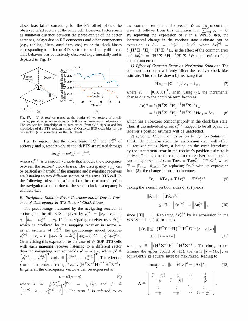
Consider a mapping receiver with knowledge of its ownstate vector (by having access to GPS signals, for example)to be present in the navigating receiver’s environment asdepicted in Fig. 16. The mapping receiver’s objective is toestimate the BTSs’ position and clock bias states and sharethese estimates with the navigating receiver through a centraldatabase. If the mapping receiver has been estimating theSOP BTSs’ states for a sufficiently long period of time,the position state estimate uncertainties will be negligible.Moreover, the position state estimates are physically verifiable(through surveying or satellite images, for example), at whichpoint these estimates are assumed to match the true states andare subsequently stored in the database. Unlike the positionstate estimates, the clock bias state estimates are more difficultto verify and are time-varying. Therefore, in the sequel, itis assumed that the mapping receiver is only estimating theBTSs’ clock bias states.
Central
Navigating
Mapping
Receiver
BTSi
Receiver
Database
BTS2
BTS1
Fig. 16. Mapping receiver and navigating receiver in SOP environment.
ConsidersM mapping receivers andN SOP BTSs. Denotethe state vector of thejth receiver byxrj , the pseudorange
measurement by thejth receiver on theith BTS byρ(j)i , andthe corresponding measurement noise byv
(j)i . Assumev(j)i to
be independent for alli and j with a corresponding variance
σ(j)i
2. Define the set of measurements made by all receivers
on theith BTS as
zi =
‖rr1 − rsi‖+ cδtr1 − ρ(1)i
...
‖rrM − rsi‖+ cδtrM − ρ(M)i
=
cδtsi − v(1)i
...
cδtsi − v(M)i
= cδtsi1M + v(j),
where1M , [1, . . . , 1]T and v(j) , −
[
v(j)1 , . . . , v
(j)N
]T
.Theclock bias δtsi is estimated by solving a weighted least-squares (WLS) problem, resulting in the estimateδtsi =1c
(
1T
MW1M
)−11T
MWz and its associated error variance
σ2δtsi
=(
1T
MW1M
)−1, whereW = diag
[
1
σ(1)i
2 , . . . ,1
σ(M)i
2
]
is the weighting matrix. The true clock bias of theith BTScan now be expressed asδtsi = δtsi + wi, wherewi is azero-mean Gaussian random variable with varianceσ2
δtsi.
C. Fusion of BTS Clock State Estimates into the NavigationSolution
Since the navigating receiver is using the estimate of theBTS clock bias, which is produced by the mapping receiver,the pseudorange measurement made by the navigating receiveron theith BTS becomes
ρi = hi(xr, xsi) + ηi,
where xsi =[
rTsi , cδtsi
]T
and ηi , vi − wi models theoverall uncertainty in the pseudorange measurement. Hence,the vectorη , [η1, . . . , ηN ]
T is a zero-mean Gaussian ran-dom vector with a covariance matrixΣ = C + R, whereC = diag
[
σ2δts1
, . . . , σ2δtsN
]
is the covariance matrix of
w , [w1, . . . , wN ]T and R = diag
[
σ21 , . . . , σ
2N
]
is the co-variance of the measurement noise vectorv = [v1, . . . , vN ]
T.The Jacobian matrixH of the set of observation functionsh , [h1(xr, xs1), . . . , hN (xr, xsN )]
T with respect toxr isgiven byH = [G 1N ], where
G ,
xr−xs1
‖rr−rs1‖yr−ys1
‖rr−rs1‖zr−zs1
‖rr−rs1‖...
......
xr−xsN
‖rr−rsN ‖yr−ysN
‖rr−rsN‖zr−zsN
‖rr−rsN‖
.
The navigating receiver’s state can now be estimated bysolving a WNLS problem, where the incremental change inthe state vector estimate per iteration is given byδxr =[
δrTr , δ(cδtr)]T
, whereδrr and δ(cδtr) are the incrementalchange in the position and the clock bias states, respec-tively, and δxr =
(
HTΣ
−1H)−1
HTΣ
−1 (ρ− h), whereρ , [ρ1, ρ2, . . . , ρN ]T and H and h are evaluated at thecurrent iteration of the state estimatexr and the BTS stateestimates{xsi}Ni=1.
D. Clock Biases of Different Sectors of a BTS
A typical CDMA BTS transmits into three different sectorswithin a particular cell. Ideally, all sectors’ clocks should bedriven by the same oscillator, which implies that the same
clock bias (after correcting for the PN offset) should beobserved in all sectors of the same cell. However, factors suchas unknown distance between the phase-center of the sectorantennas, delays due to RF connectors and other components(e.g., cabling, filters, amplifiers, etc.) cause the clock biasescorresponding to different BTS sectors to be slightly different.This behavior was consistently observed experimentally and isdepicted in Fig. 17.
Sector p
Sector q
Time [s]
Sector pSector q
Observedclockbiases
for
SectorAntenna
BTS Cell(a) (b)
differentBTSsectors[s]
Fig. 17. (a) A receiver placed at the border of two sectors of acell,making pseudorange observations on both sector antennas simultaneously.The receiver has knowledge of its own states (from GPS signals) and hasknowledge of the BTS position states. (b) Observed BTS clockbias for thetwo sectors (after correcting for the PN offset).
Fig. 17 suggest that the clock biasesδt(p)si and δt(q)si ofsectorsp andq, respectively, of theith BTS are related through
cδt(q)si = cδt(p)si + ǫ(p,q)i ,
whereǫ(p,q)i is a random variable that models the discrepancybetween the sectors’ clock biases. The discrepancyǫip,q canbe particulary harmful if the mapping and navigating receiversare listening to two different sectors of the same BTS cell. Inthe following subsection, a bound on the error introduced inthe navigation solution due to the sector clock discrepancyischaracterized.
E. Navigation Solution Error Characterization Due to Pres-ence of Discrepancy in BTS Sectors’ Clock Biases
The pseudorange measured by the navigating receiver insector q of the ith BTS is given byρ(q)i = ‖rr − rsi‖ +
c ·[
δtr − δt(q)si
]
+ vi. If the navigating receiver usesδt(p)
si,
which is produced by the mapping receiver in sectorp,as an estimate ofδt(q)si , the pseudorange model becomes
ρ′(q)i = ‖rr − rsi‖+c·
[
δtr − δt(q)
si
]
+ηi+ǫ(p,q)i = ρ
(q)i +ǫ
(p,q)i .
Generalizing this expression to the case ofN SOP BTS cellswith each mapping receiver listening to a different sectorthan the navigating receiver yieldsρ′ = ρ + ǫ, whereρ′ ,[
ρ′(q)1 , . . . , ρ
′(q)N
]T
andǫ ,[
ǫ(p,q)1 , . . . , ǫ
(p,q)N
]T
. The effect of
ǫ on the incremental changeδxr is(
HTΣ
−1H)−1
HTΣ
−1ǫ.In general, the discrepancy vectorǫ can be expressed as
ǫ = b1N +ψ, (6)
where b , 1N
∑Ni=1 ǫ
(p,q)i = 1
N1T
Nǫ, and ψ ,[
ǫ(p,q)1 − b, . . . , ǫ
(p,q)N − b
]T
. The term b is referred to as
the common error and the vectorψ as the uncommonerror. It follows from this definition that
∑Ni=1 ψi = 0.
By replacing the expression ofǫ in a WNLS step, theincremental change in the receiver state estimate can beexpressed asδxr = δx
(b)r + δx
(ψ)r , where δx
(b)r =
b(
HTΣ
−1H)−1
HTΣ
−11N is the effect of the common error
and δx(ψ)r =
(
HTΣ
−1H)−1
HTΣ
−1ψ is the effect of theuncommon error.
1) Effect of Common Error on Navigation Solution: Thecommon error term will only affect the receiver clock biasestimate. This can be shown by realizing that
He4 = [G 1N ] e4 = 1N , (7)
where e4 = [0, 0, 0, 1]T. Then, using (7), the incremental
change due to the common term becomes
δx(b)r = b
(
HTΣ
−1H)−1
HTΣ
−11N
= b(
HTΣ
−1H)−1
HTΣ
−1He4 = be4, (8)
which has a non-zero component only in the clock bias state.Thus, if the individual errorsǫ(p,q)i happen to be all equal, thereceiver’s position estimate will be unaffected.
2) Effect of Uncommon Error on Navigation Solution:Unlike the common error, the uncommon error will affectall receiver states. Next, a bound on the error introducedby the uncommon error in the receiver’s position estimate isderived. The incremental change in the receiver position statecan be expressed asδrr = Tδxr = Tδx
(b)r +Tδx
(ψ)r , where
T = [I3×3 03×1]. By replacingδx(b)r with its expression
from (8), the change in position becomes
δrr = bTe4 +Tδx(ψ)r = Tδx(ψ)
r . (9)
Taking the 2-norm on both sides of (9) yields
‖δrr‖ =∥
∥
∥Tδx(ψ)
r
∥
∥
∥
≤ ‖T‖ ·∥
∥
∥δx(ψ)
r
∥
∥
∥=
∥
∥
∥δx(ψ)
r
∥
∥
∥, (10)
since ‖T‖ = 1. Replacingδx(ψ)r by its expression in the
WNLS update, (10) becomes
‖δrr‖ ≤∥
∥
∥
(
HTΣ
−1H)−1
HTΣ
−1 (ǫ− b1N )∥
∥
∥
≤ γ ‖ǫ− b1N‖ , (11)
where γ ,
∥
∥
∥
(
HTΣ
−1H)−1
HTΣ
−1∥
∥
∥. Therefore, to de-
termine the upper bound of (11), the term‖ǫ− b1N‖, orequivalently its square, must be maximized, leading to
maximizeǫ
‖ǫ− b1N‖2 = ‖Aǫ‖2 , (12)
A ,
(1− 1N) − 1
N· · · − 1
N
− 1N
(1− 1N) · · · − 1
N...
.... . .
...− 1N
− 1N
· · · (1− 1N)
.
Motivated by experimental data collected in different BTS cellsectors and for various cells, it is reasonable to assume that
|ǫ(p,q)i | ≤ α, ∀ i, (13)
whereα is some positive constant. As such, the maximizationproblem in (12) becomes constrained by (13). The function in(12) is convex, since it is the composition of the norm with alinear mapping, and the box constraints in (13) form a convexset. Therefore, the maximizer of (12) subject to the constraints(13) lies on the extreme points of the feasibility region, namely∣
∣
∣
(
ǫ(p,q)i
)⋆∣∣
∣= α, ∀ i.
If N is even, the maximum is achieved whenever∑N
i=1 ǫ(p,q)i = 0; hence, the maximizer is
(
ǫ(p,q)i
)⋆
=
(−1)iα, ∀ i. If N is odd, the maximum is achieved whenever
∑N
i=1 ǫ(p,q)i = |α|; hence, the maximizer is
(
ǫ(p,q)i
)⋆
=
(−1)iα for i = 1, . . . , N−1, and
(
ǫ(p,q)N
)⋆
= ±α. Therefore,the maximum error introduced in the receiver’s position isbounded by
‖δrr‖ ≤{ √
Nαγ, if N is even,√
N2−1N
αγ, if N is odd.
V. EXPERIMENTAL RESULTS
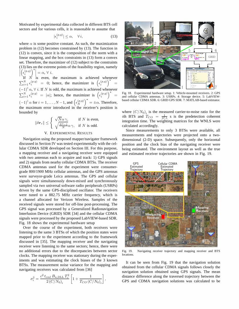
Navigation using the proposed mapper/navigater frameworkdiscussed in Section IV was tested experimentally with the cel-lular CDMA SDR developed on Section III. For this purpose,a mapping receiver and a navigating receiver were equippedwith two antennas each to acquire and track: 1) GPS signalsand 2) signals from nearby cellular CDMA BTSs. The receiverCDMA antennas used for the experiment were consumer-grade 800/1900 MHz cellular antennas, and the GPS antennaswere surveyor-grade Leica antennas. The GPS and cellularsignals were simultaneously down-mixed and synchronouslysampled via two universal software radio peripherals (USRPs)driven by the same GPS-disciplined oscillator. The receiverswere tuned to a 882.75 MHz carrier frequency, which isa channel allocated for Verizon Wireless. Samples of thereceived signals were stored for off-line post-processing. TheGPS signal was processed by a Generalized RadionavigationInterfusion Device (GRID) SDR [34] and the cellular CDMAsignals were processed by the proposed LabVIEW-based SDR.Fig. 18 shows the experimental hardware setup
Over the course of the experiment, both receivers werelistening to the same 3 BTSs of which the position states weremapped prior to the experiment according to the frameworkdiscussed in [35]. The mapping receiver and the navigatingreceiver were listening to the same sectors; hence, there wereno additional errors due to the discrepancies between sectorclocks. The mapping receiver was stationary during the exper-iments and was estimating the clock biases of the 3 knownBTSs. The measurement noise variance for the mapping andnavigating receivers was calculated from [36]
σ2i =
c2 teml Bn,DLL T2c
2 (C/N0)i
[
1 +1
TCO (C/N0)i
]
,
GRID
1
2 3 4
5 6
7
Fig. 18. Experimental hardware setup. 1: Vehicle-mounted receivers. 2: GPSand cellular CDMA antennas. 3: USRPs. 4: Storage device. 5: LabVIEW-based cellular CDMA SDR. 6: GRID GPS SDR. 7: MATLAB-based estimator.
where(C/N0)i is the measured carrier-to-noise ratio for theith BTS andTCO = 1
37.5 s is the predetection coherentintegration time. The weighting matrices for the WNLS werecalculated accordingly.
Since measurements to only 3 BTSs were available, allmeasurements and trajectories were projected onto a two-dimensional (2-D) space. Subsequently, only the horizontalposition and the clock bias of the navigating receiver werebeing estimated. The environment layout as well as the trueand estimated receiver trajectories are shown in Fig. 19.
Estimated Estimated
BTS1
NavigatingReceiver
Trajectory Trajectory
Cellular CDMAGPS
BTS2
BTS3
MappingReceiver
Fig. 19. Navigating receiver trajectory and mapping receiver and BTSlocations.
It can be seen from Fig. 19 that the navigation solutionobtained from the cellular CDMA signals follows closely thenavigation solution obtained using GPS signals. The meandistance difference along the traversed trajectory between theGPS and CDMA navigation solutions was calculated to be
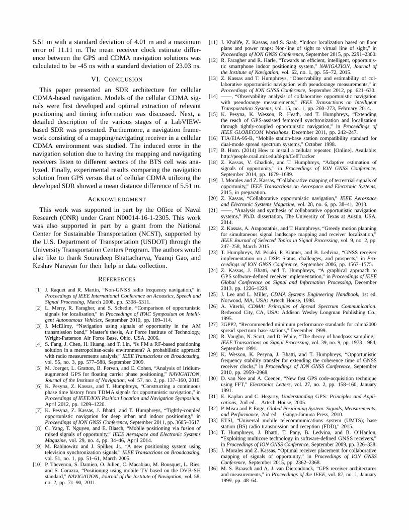
5.51 m with a standard deviation of 4.01 m and a maximumerror of 11.11 m. The mean receiver clock estimate differ-ence between the GPS and CDMA navigation solutions wascalculated to be -45 ns with a standard deviation of 23.03 ns.
VI. CONCLUSION
This paper presented an SDR architecture for cellularCDMA-based navigation. Models of the cellular CDMA sig-nals were first developed and optimal extraction of relevantpositioning and timing information was discussed. Next, adetailed description of the various stages of a LabVIEW-based SDR was presented. Furthermore, a navigation frame-work consisting of a mapping/navigating receiver in a cellularCDMA environment was studied. The induced error in thenavigation solution due to having the mapping and navigatingreceivers listen to different sectors of the BTS cell was ana-lyzed. Finally, experimental results comparing the navigationsolution from GPS versus that of cellular CDMA utilizing thedeveloped SDR showed a mean distance difference of 5.51 m.
ACKNOWLEDGMENT
This work was supported in part by the Office of NavalResearch (ONR) under Grant N00014-16-1-2305. This workwas also supported in part by a grant from the NationalCenter for Sustainable Transportation (NCST), supported bythe U.S. Department of Transportation (USDOT) through theUniversity Transportation Centers Program. The authors wouldalso like to thank Souradeep Bhattacharya, Yuanqi Gao, andKeshav Narayan for their help in data collection.
REFERENCES
[1] J. Raquet and R. Martin, “Non-GNSS radio frequency navigation,” inProceedings of IEEE International Conference on Acoustics, Speech andSignal Processing, March 2008, pp. 5308–5311.
[2] L. Merry, R. Faragher, and S. Schedin, “Comparison of opportunisticsignals for localisation,” inProceedings of IFAC Symposium on Intelli-gent Autonomous Vehicles, September 2010, pp. 109–114.
[3] J. McEllroy, “Navigation using signals of opportunity in the AMtransmission band,” Master’s thesis, Air Force Institute of Technology,Wright-Patterson Air Force Base, Ohio, USA, 2006.
[4] S. Fang, J. Chen, H. Huang, and T. Lin, “Is FM a RF-based positioningsolution in a metropolitan-scale environment? A probabilistic approachwith radio measurements analysis,”IEEE Transactions on Broadcasting,vol. 55, no. 3, pp. 577–588, September 2009.
[5] M. Joerger, L. Gratton, B. Pervan, and C. Cohen, “Analysis of Iridium-augmented GPS for floating carrier phase positioning,”NAVIGATION,Journal of the Institute of Navigation, vol. 57, no. 2, pp. 137–160, 2010.
[6] K. Pesyna, Z. Kassas, and T. Humphreys, “Constructing a continuousphase time history from TDMA signals for opportunistic navigation,” inProceedings of IEEE/ION Position Location and Navigation Symposium,April 2012, pp. 1209–1220.
[7] K. Pesyna, Z. Kassas, J. Bhatti, and T. Humphreys, “Tightly-coupledopportunistic navigation for deep urban and indoor positioning,” inProceedings of ION GNSS Conference, September 2011, pp. 3605–3617.
[8] C. Yang, T. Nguyen, and E. Blasch, “Mobile positioning via fusion ofmixed signals of opportunity,”IEEE Aerospace and Electronic SystemsMagazine, vol. 29, no. 4, pp. 34–46, April 2014.
[9] M. Rabinowitz and J. Spilker, Jr., “A new positioning system usingtelevision synchronization signals,”IEEE Transactions on Broadcasting,vol. 51, no. 1, pp. 51–61, March 2005.
[10] P. Thevenon, S. Damien, O. Julien, C. Macabiau, M. Bousquet, L. Ries,and S. Corazza, “Positioning using mobile TV based on the DVB-SHstandard,”NAVIGATION, Journal of the Institute of Navigation, vol. 58,no. 2, pp. 71–90, 2011.
[11] J. Khalife, Z. Kassas, and S. Saab, “Indoor localization based on floorplans and power maps: Non-line of sight to virtual line of sight,” inProceedings of ION GNSS Conference, September 2015, pp. 2291–2300.
[12] R. Faragher and R. Harle, “Towards an efficient, intelligent, opportunis-tic smartphone indoor positioning system,”NAVIGATION, Journal ofthe Institute of Navigation, vol. 62, no. 1, pp. 55–72, 2015.
[13] Z. Kassas and T. Humphreys, “Observability and estimability of col-laborative opportunistic navigation with pseudorange measurements,” inProceedings of ION GNSS Conference, September 2012, pp. 621–630.
[14] ——, “Observability analysis of collaborative opportunistic navigationwith pseudorange measurements,”IEEE Transactions on IntelligentTransportation Systems, vol. 15, no. 1, pp. 260–273, February 2014.
[15] K. Pesyna, K. Wesson, R. Heath, and T. Humphreys, “Extendingthe reach of GPS-assisted femtocell synchronization and localizationthrough tightly-coupled opportunistic navigation,” inProceedings ofIEEE GLOBECOM Workshops, December 2011, pp. 242–247.
[16] TIA/EIA-95-B, “Mobile station-base station compatibility standard fordual-mode spread spectrum systems,” October 1998.
[17] B. Horn. (2014) How to install a cellular repeater. [Online]. Available:http://people.csail.mit.edu/bkph/CellTracker
[18] Z. Kassas, V. Ghadiok, and T. Humphreys, “Adaptive estimation ofsignals of opportunity,” inProceedings of ION GNSS Conference,September 2014, pp. 1679–1689.
[19] J. Morales and Z. Kassas, “Collaborative mapping of terrestrial signals ofopportunity,” IEEE Transactions on Aerospace and Electronic Systems,2015, in preparation.
[20] Z. Kassas, “Collaborative opportunistic navigation,” IEEE Aerospaceand Electronic Systems Magazine, vol. 28, no. 6, pp. 38–41, 2013.
[21] ——, “Analysis and synthesis of collaborative opportunistic navigationsystems,” Ph.D. dissertation, The University of Texas at Austin, USA,2014.
[22] Z. Kassas, A. Arapostathis, and T. Humphreys, “Greedy motion planningfor simultaneous signal landscape mapping and receiver localization,”IEEE Journal of Selected Topics in Signal Processing, vol. 9, no. 2, pp.247–258, March 2015.
[23] T. Humphreys, M. Psiaki, P. Kintner, and B. Ledvina, “GNSS receiverimplementation on a DSP: Status, challenges, and prospects,” in Pro-ceedings of ION GNSS Conference, September 2006, pp. 1567–1575.
[24] Z. Kassas, J. Bhatti, and T. Humphreys, “A graphical approach toGPS software-defined receiver implementation,” inProceedings of IEEEGlobal Conference on Signal and Information Processing, December2013, pp. 1226–1229.
[25] J. Lee and L. Miller,CDMA Systems Engineering Handbook, 1st ed.Norwood, MA, USA: Artech House, 1998.
[26] A. Viterbi, CDMA: Principles of Spread Spectrum Communication.Redwood City, CA, USA: Addison Wesley Longman Publishing Co.,1995.
[27] 3GPP2, “Recommended minimum performance standards for cdma2000spread spectrum base stations,” December 1999.
[28] R. Vaughn, N. Scott, and D. White, “The theory of bandpass sampling,”IEEE Transactions on Signal Processing, vol. 39, no. 9, pp. 1973–1984,September 1991.
[29] K. Wesson, K. Pesyna, J. Bhatti, and T. Humphreys, “Opportunisticfrequency stability transfer for extending the coherence time of GNSSreceiver clocks,” inProceedings of ION GNSS Conference, September2010, pp. 2959–2968.
[30] D. van Nee and A. Coenen, “New fast GPS code-acquisitiontechniqueusing FFT,” Electronics Letters, vol. 27, no. 2, pp. 158–160, January1991.
[31] E. Kaplan and C. Hegarty,Understanding GPS: Principles and Appli-cations, 2nd ed. Artech House, 2005.
[32] P. Misra and P. Enge,Global Positioning System: Signals, Measurements,and Performance, 2nd ed. Ganga-Jamuna Press, 2010.
[33] ETSI, “Universal mobile telecommunications system (UMTS); basestation (BS) radio transmission and reception (FDD),” 2015.
[34] T. Humphreys, J. Bhatti, T. Pany, B. Ledvina, and B. O’Hanlon,“Exploiting multicore technology in software-defined GNSSreceivers,”in Proceedings of ION GNSS Conference, September 2009, pp. 326–338.
[35] J. Morales and Z. Kassas, “Optimal receiver placement for collaborativemapping of signals of opportunity,” inProceedings of ION GNSSConference, September 2015, pp. 2362–2368.
[36] M. S. Braasch and A. J. van Dierendonck, “GPS receiver architecturesand measurements,” inProceedings of the IEEE, vol. 87, no. 1, January1999, pp. 48–64.


![A Survey on Software-Defined Network and OpenFlow: From ... list/papers...Such an idea is defined in an innovative technology, called Software-Defined Networking (SDN) [4]. Its](https://img.pdfslide.us/doc/110x75/60e08556585db628f1249f4c/a-survey-on-software-deined-network-and-openflow-from-listpapers-such.jpg)