Embed Size (px)
Citation preview
70 The Open Transportation Journal, 2009, 3, 70-77
1874-4478/09 2009 Bentham Open
Open Access
A Small-Scale CAN-Based PM BLDC Motor Control for Automotive Accessory Electrification and Electric Traction
Qunfang Liao1, Y. Gene Liao
*,2 and Chih-Ping Yeh
2
1Panasonic Automotive Systems, Peachtree City, Georgia, USA
2Wayne State University, Detroit, Michigan, USA
Abstract: This paper presents the development of an experimental platform to test a real-time controller for a small
Permanent Magnetic Brushless Direct Current (PM BLDC) motor using a Controller Area Network (CAN)
communication bus. The CAN communication bus transmits and receives information between modules to control the
speed, acceleration/deceleration, and rotational direction of the motor. The design consists of five major hardwares: single
chip microcontroller, three module boards, PM BLDC motor, logic-input quad driver, and a power logic level gate driver.
Microcontroller software is developed to perform eight major functions: controller initialization, service interrupt
generation, switch, display, power converter, CAN communication, pulse width modulation control, and actual motor
speed measurement. The motivation of this work is to acquire a better understanding of the PM BLDC motor control and
CAN system in a laboratory setting. This work is important because electric drivetrain, accessory electrification, and the
CAN communication system are key elements in electric and hybrid electric vehicles.
Keywords: Automotive accessory electrification, CAN, Electric drivetrain, Motor control, PM BLDC motor, Traction motor.
1. INTRODUCTION
Electric drivetrain and electrically powered automotive subsystems are at the heart of the Electric Vehicle (EV) and Hybrid Electric Vehicle (HEV). The traction motor in the electric drivetrain is a major propulsion component for vehicle powertrain hybridization. Electrification of vehicle auxiliary functions, such as hydraulic power steering, engine cooling system, etc., is essential to the EV and HEV because the EV has no engine and the HEV frequently has the engine turned off to conserve energy. For an instance, an electric air conditioning compressor (powered by the electric motor/battery instead of mechanical engine belts) allows air conditioning to function even when the engine shuts off during vehicle stops. Other examples of such applications include water pump, oil pump, fuel pump, air compressor, variable valve actuator, power steering pump, and many more.
Electrically powered automotive accessories, instead of mechanically powered ones, allow the accessories to operate independently of the engine so they can perform at the precise speed, pressure, or flow rate required. Accessory electrification provides the following benefits: fuel savings, thermal load reductions, emission reductions, significant flexibility in placing components inside the engine compartment, and a great potential for enhancements [1-4]. Either using a traction motor to propel the vehicle or an electric motor (replacing the conventional belt-driven hydraulic pump/comp-ressor) to delivery auxiliary functions requires a motor driver or a motor controller. Additionally, there are a large number of electric motors inside the
*Address correspondence to this author at the Division of Engineering
Technology, Wayne State University, Detroit, Michigan 48202, USA;
E-mail: [email protected]
conventional vehicle and this number is growing as more options are being incorporated [5]. Some examples of use of motors inside the vehicle are window rolling functions, wiper control, seat and mirror movements and others. Controllers are also needed for these motors.
A typical motor control system consists of an electric motor, power converter, electronic controller and information network such as a Controller Area Network (CAN). The power converter supplies the proper voltage and current to the electric motors. The electronic controller manages the command signals to the power converter and then controls the operation of the electric motor to produce the required torque and speed. These command signals and information are transmitted through the CAN bus.
Differing from the industrial applications of motors, the motors used in electric drivetrain and accessories usually require frequent stops and starts, high rates of acceleration/deceleration, high torque and low-speed hill climbing, low torque and high-speed cruising, and a very wide speed range of operation. The motor drives can be classified into two main groups, namely the commutator motors and commutatorless motors. Commutator motors are the traditional direct current (DC) motors which need commutators and brushes to feed current into the armature, thus making them less reliable and unsuitable for maintenance-free operation and high speed. Commutatorless motors are more reliable and maintenance-free and have four types: induction motor, Permanent Magnetic Brushless Alternating Current (PM BLAC) motor, Permanent Magnetic Brushless DC (PM BLDC) motor, and switched reluctance motor. Recent advancements in permanent magnetic materials and motor design have made the PM BLDC motor a great candidate for automotive electric traction and accessory electrification applications [6-11]. It
A Small-Scale CAN-Based PM BLDC Motor Control The Open Transportation Journal, 2009, Volume 3 71
should be noted that the term “DC” in PM BLDC motor may be misleading since it dose not refer to a DC current motor. Actually, these motors are fed by rectangular AC current, and are hence also known as rectangular-fed PM brushless motors.
In a modern vehicle, inter-module communication between lots of control modules requires dedicated and point-to-point wiring resulting in bulky, expensive, and complex wiring harnesses. However, the number of wires can be greatly reduced by applying a serial data bus which combines the signals on a single wire through time division multiplexing. CAN is a serial bus communications protocol initially created by German automotive system supplier Robert Bosch in the mid-1980s for automotive applications as a method for enabling robust serial communication [12]. CAN defines a standard for efficient and reliable communication between sensor, actuator, controller, and other nodes in real-time applications and its goal is to make automobiles more reliable, safe and fuel-efficient while decreasing wiring harness weight and complexity. Since its inception, the CAN protocol has gained widespread popularity in automotive applications [13-15].
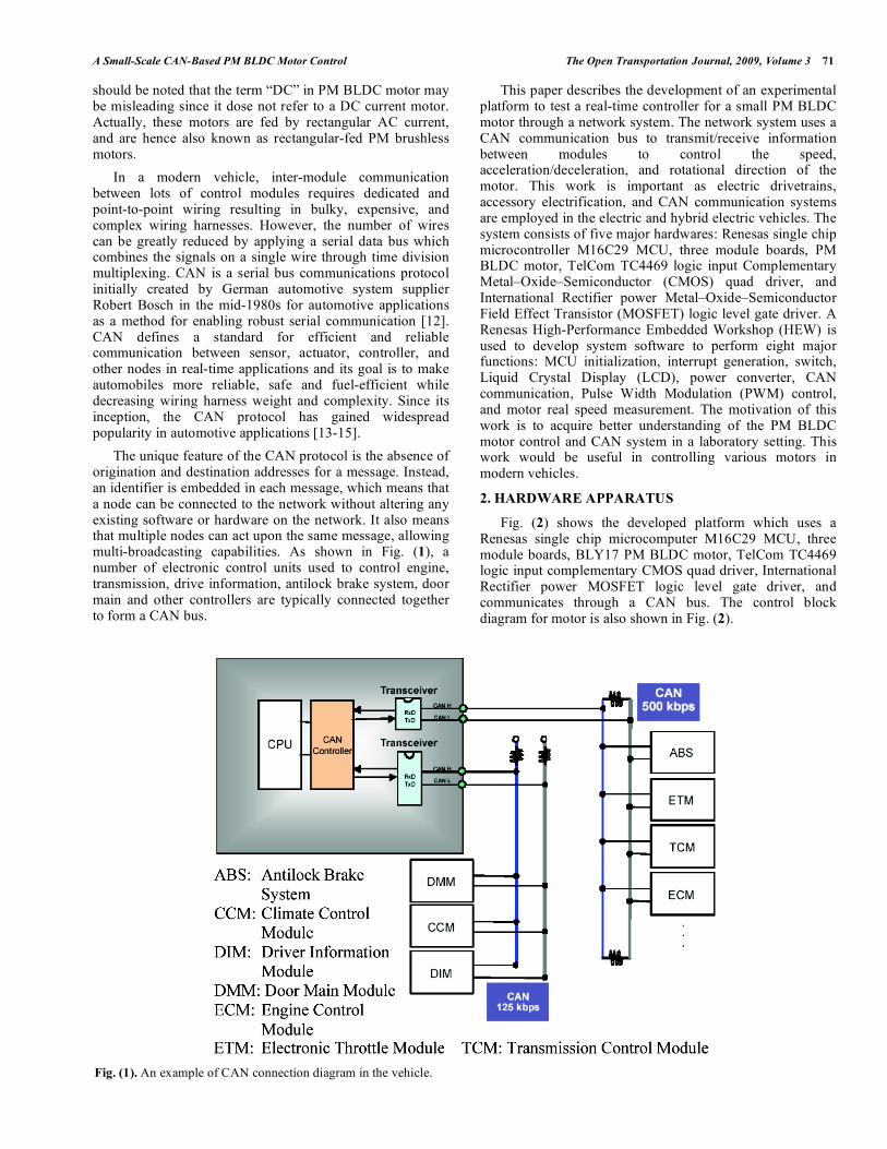
The unique feature of the CAN protocol is the absence of origination and destination addresses for a message. Instead, an identifier is embedded in each message, which means that a node can be connected to the network without altering any existing software or hardware on the network. It also means that multiple nodes can act upon the same message, allowing multi-broadcasting capabilities. As shown in Fig. (1), a number of electronic control units used to control engine, transmission, drive information, antilock brake system, door main and other controllers are typically connected together to form a CAN bus.
This paper describes the development of an experimental platform to test a real-time controller for a small PM BLDC motor through a network system. The network system uses a CAN communication bus to transmit/receive information between modules to control the speed, acceleration/deceleration, and rotational direction of the motor. This work is important as electric drivetrains, accessory electrification, and CAN communication systems are employed in the electric and hybrid electric vehicles. The system consists of five major hardwares: Renesas single chip microcontroller M16C29 MCU, three module boards, PM BLDC motor, TelCom TC4469 logic input Complementary Metal–Oxide–Semiconductor (CMOS) quad driver, and International Rectifier power Metal–Oxide–Semiconductor Field Effect Transistor (MOSFET) logic level gate driver. A Renesas High-Performance Embedded Workshop (HEW) is used to develop system software to perform eight major functions: MCU initialization, interrupt generation, switch, Liquid Crystal Display (LCD), power converter, CAN communication, Pulse Width Modulation (PWM) control, and motor real speed measurement. The motivation of this work is to acquire better understanding of the PM BLDC motor control and CAN system in a laboratory setting. This work would be useful in controlling various motors in modern vehicles.
2. HARDWARE APPARATUS
Fig. (2) shows the developed platform which uses a Renesas single chip microcomputer M16C29 MCU, three module boards, BLY17 PM BLDC motor, TelCom TC4469 logic input complementary CMOS quad driver, International Rectifier power MOSFET logic level gate driver, and communicates through a CAN bus. The control block diagram for motor is also shown in Fig. (2).
Fig. (1). An example of CAN connection diagram in the vehicle.
72 The Open Transportation Journal, 2009, Volume 3 Liao et al.
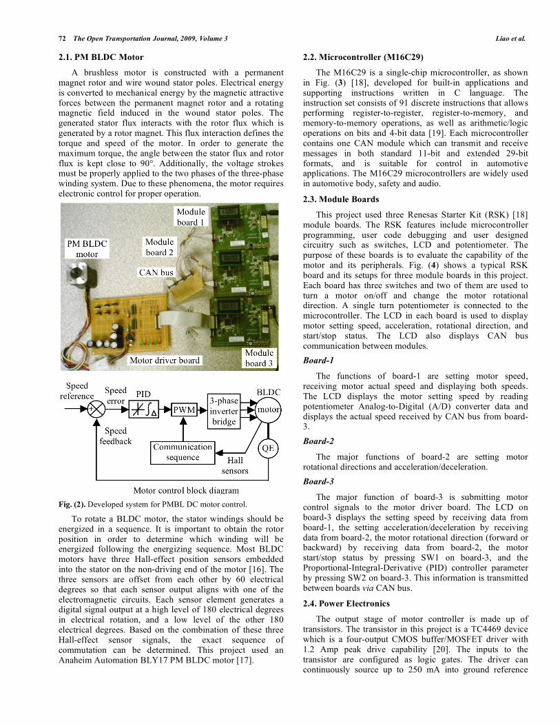
2.1. PM BLDC Motor
A brushless motor is constructed with a permanent magnet rotor and wire wound stator poles. Electrical energy is converted to mechanical energy by the magnetic attractive forces between the permanent magnet rotor and a rotating magnetic field induced in the wound stator poles. The generated stator flux interacts with the rotor flux which is generated by a rotor magnet. This flux interaction defines the torque and speed of the motor. In order to generate the maximum torque, the angle between the stator flux and rotor flux is kept close to 90°. Additionally, the voltage strokes must be properly applied to the two phases of the three-phase winding system. Due to these phenomena, the motor requires electronic control for proper operation.
Fig. (2). Developed system for PMBL DC motor control.
To rotate a BLDC motor, the stator windings should be energized in a sequence. It is important to obtain the rotor position in order to determine which winding will be energized following the energizing sequence. Most BLDC motors have three Hall-effect position sensors embedded into the stator on the non-driving end of the motor [16]. The three sensors are offset from each other by 60 electrical degrees so that each sensor output aligns with one of the electromagnetic circuits. Each sensor element generates a digital signal output at a high level of 180 electrical degrees in electrical rotation, and a low level of the other 180 electrical degrees. Based on the combination of these three Hall-effect sensor signals, the exact sequence of commutation can be determined. This project used an Anaheim Automation BLY17 PM BLDC motor [17].
2.2. Microcontroller (M16C29)
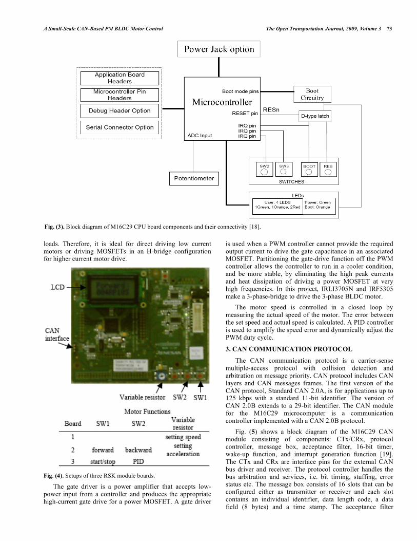
The M16C29 is a single-chip microcontroller, as shown in Fig. (3) [18], developed for built-in applications and supporting instructions written in C language. The instruction set consists of 91 discrete instructions that allows performing register-to-register, register-to-memory, and memory-to-memory operations, as well as arithmetic/logic operations on bits and 4-bit data [19]. Each microcontroller contains one CAN module which can transmit and receive messages in both standard 11-bit and extended 29-bit formats, and is suitable for control in automotive applications. The M16C29 microcontrollers are widely used in automotive body, safety and audio.
2.3. Module Boards
This project used three Renesas Starter Kit (RSK) [18] module boards. The RSK features include microcontroller programming, user code debugging and user designed circuitry such as switches, LCD and potentiometer. The purpose of these boards is to evaluate the capability of the motor and its peripherals. Fig. (4) shows a typical RSK board and its setups for three module boards in this project. Each board has three switches and two of them are used to turn a motor on/off and change the motor rotational direction. A single turn potentiometer is connected to the microcontroller. The LCD in each board is used to display motor setting speed, acceleration, rotational direction, and start/stop status. The LCD also displays CAN bus communication between modules.
Board-1
The functions of board-1 are setting motor speed, receiving motor actual speed and displaying both speeds. The LCD displays the motor setting speed by reading potentiometer Analog-to-Digital (A/D) converter data and displays the actual speed received by CAN bus from board-3.
Board-2
The major functions of board-2 are setting motor rotational directions and acceleration/deceleration.
Board-3
The major function of board-3 is submitting motor control signals to the motor driver board. The LCD on board-3 displays the setting speed by receiving data from board-1, the setting acceleration/deceleration by receiving data from board-2, the motor rotational direction (forward or backward) by receiving data from board-2, the motor start/stop status by pressing SW1 on board-3, and the Proportional-Integral-Derivative (PID) controller parameter by pressing SW2 on board-3. This information is transmitted between boards via CAN bus.
2.4. Power Electronics
The output stage of motor controller is made up of transistors. The transistor in this project is a TC4469 device which is a four-output CMOS buffer/MOSFET driver with 1.2 Amp peak drive capability [20]. The inputs to the transistor are configured as logic gates. The driver can continuously source up to 250 mA into ground reference
A Small-Scale CAN-Based PM BLDC Motor Control The Open Transportation Journal, 2009, Volume 3 73
loads. Therefore, it is ideal for direct driving low current motors or driving MOSFETs in an H-bridge configuration for higher current motor drive.
Fig. (4). Setups of three RSK module boards.
The gate driver is a power amplifier that accepts low-power input from a controller and produces the appropriate high-current gate drive for a power MOSFET. A gate driver
is used when a PWM controller cannot provide the required output current to drive the gate capacitance in an associated MOSFET. Partitioning the gate-drive function off the PWM controller allows the controller to run in a cooler condition, and be more stable, by eliminating the high peak currents and heat dissipation of driving a power MOSFET at very high frequencies. In this project, IRLI3705N and IRF5305 make a 3-phase-bridge to drive the 3-phase BLDC motor.
The motor speed is controlled in a closed loop by measuring the actual speed of the motor. The error between the set speed and actual speed is calculated. A PID controller is used to amplify the speed error and dynamically adjust the PWM duty cycle.
3. CAN COMMUNICATION PROTOCOL
The CAN communication protocol is a carrier-sense multiple-access protocol with collision detection and arbitration on message priority. CAN protocol includes CAN layers and CAN messages frames. The first version of the CAN protocol, Standard CAN 2.0A, is for applications up to 125 kbps with a standard 11-bit identifier. The version of CAN 2.0B extends to a 29-bit identifier. The CAN module for the M16C29 microcomputer is a communication controller implemented with a CAN 2.0B protocol.
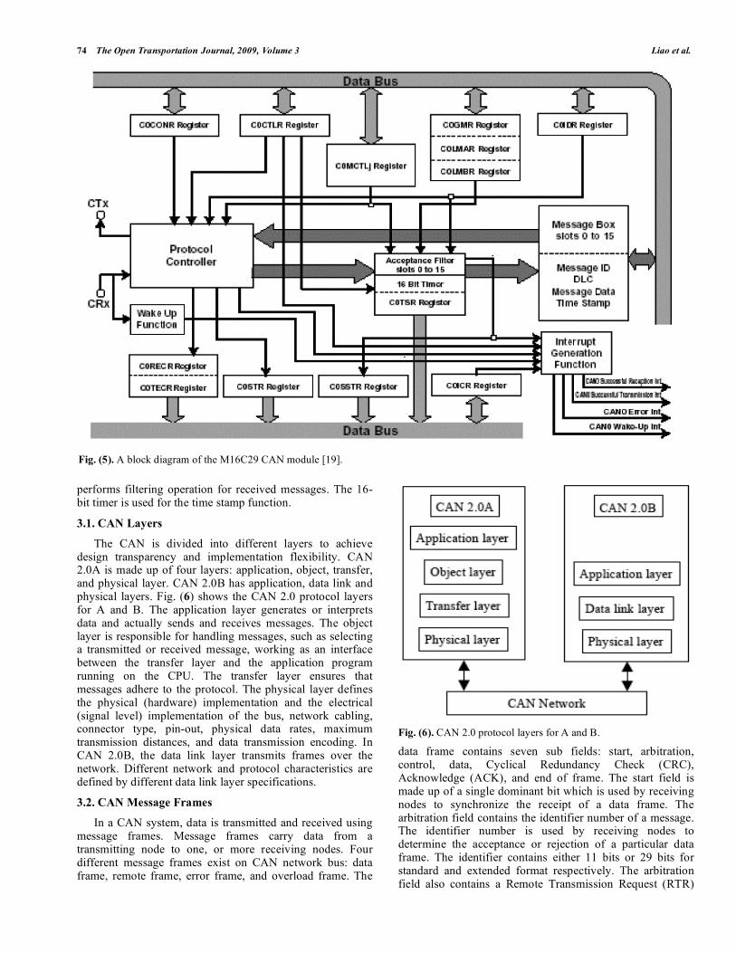
Fig. (5) shows a block diagram of the M16C29 CAN module consisting of components: CTx/CRx, protocol controller, message box, acceptance filter, 16-bit timer, wake-up function, and interrupt generation function [19]. The CTx and CRx are interface pins for the external CAN bus driver and receiver. The protocol controller handles the bus arbitration and services, i.e. bit timing, stuffing, error status etc. The message box consists of 16 slots that can be configured either as transmitter or receiver and each slot contains an individual identifier, data length code, a data field (8 bytes) and a time stamp. The acceptance filter
Fig. (3). Block diagram of M16C29 CPU board components and their connectivity [18].
74 The Open Transportation Journal, 2009, Volume 3 Liao et al.
performs filtering operation for received messages. The 16-bit timer is used for the time stamp function.
3.1. CAN Layers
The CAN is divided into different layers to achieve design transparency and implementation flexibility. CAN 2.0A is made up of four layers: application, object, transfer, and physical layer. CAN 2.0B has application, data link and physical layers. Fig. (6) shows the CAN 2.0 protocol layers for A and B. The application layer generates or interprets data and actually sends and receives messages. The object layer is responsible for handling messages, such as selecting a transmitted or received message, working as an interface between the transfer layer and the application program running on the CPU. The transfer layer ensures that messages adhere to the protocol. The physical layer defines the physical (hardware) implementation and the electrical (signal level) implementation of the bus, network cabling, connector type, pin-out, physical data rates, maximum transmission distances, and data transmission encoding. In CAN 2.0B, the data link layer transmits frames over the network. Different network and protocol characteristics are defined by different data link layer specifications.
3.2. CAN Message Frames
In a CAN system, data is transmitted and received using message frames. Message frames carry data from a transmitting node to one, or more receiving nodes. Four different message frames exist on CAN network bus: data frame, remote frame, error frame, and overload frame. The
Fig. (6). CAN 2.0 protocol layers for A and B.
data frame contains seven sub fields: start, arbitration, control, data, Cyclical Redundancy Check (CRC), Acknowledge (ACK), and end of frame. The start field is made up of a single dominant bit which is used by receiving nodes to synchronize the receipt of a data frame. The arbitration field contains the identifier number of a message. The identifier number is used by receiving nodes to determine the acceptance or rejection of a particular data frame. The identifier contains either 11 bits or 29 bits for standard and extended format respectively. The arbitration field also contains a Remote Transmission Request (RTR)
Fig. (5). A block diagram of the M16C29 CAN module [19].
A Small-Scale CAN-Based PM BLDC Motor Control The Open Transportation Journal, 2009, Volume 3 75
bit that is used to distinguish a data frame from a remote frame. The control field contains four bits that specify the data length in bytes. The data length is specified by four separate bits, allowing data lengths from one to eight bytes. The data field contains the actual transfer message. For each byte, the most significant bit is transmitted first. The CRC field is used to test the validity of the data received. The CRC ends with a CRC delimiter bit. The ACK field contains an ACK slot and an ACK delimiter. The ACK slot is used by a receiving node to inform the transmitter that a message (data frame) has been accepted correctly by sending one dominant bit within the ACK slot. The ACK delimiter bit is a single recessive bit. The last field, the end of frame field, consists of seven recessive bits.
4. MOTOR SPEED CONTROL
TimerS in the M16C29 microcontroller is a multifunctional input/output port for time measurement and waveform generation. A TimerS value is measured 6 times in one electrical cycle on every transition from Hall-effect sensor. This electrical cycle repeats as many times as the number of rotor pole pairs to complete a mechanical rotation. For example, if the rotor has two pole pairs, the electrical cycle repeats twice for one mechanical rotation of the shaft. The TimerS value is averaged over one rotation and the averaged value is used to determine the motor actual speed. Translating the TimerS value into motor speed depends upon three factors: operating frequency, TimerS prescale and number of rotor pole pairs. The motor actual speed, setting speed and trace speed is calculated by Eqs. (1), (2), and (3) respectively.
Actual speed in RPS = operating frequency/ (TimerS count x TimerS prescale x Number of pole pairs x 6) … (1)
Setting speed = rated motor speed x Analog-to-Digital Converter (ADC) value / maximum ADC value … (2)
where ADC converts analog input to a digital value. The ADC also introduces errors due to finite intervals in time between samples and finite number of binary output values.
Trace Speed = Setting Acceleration x Counter (10ms unit) / 10000 (10ms unit) … (3)
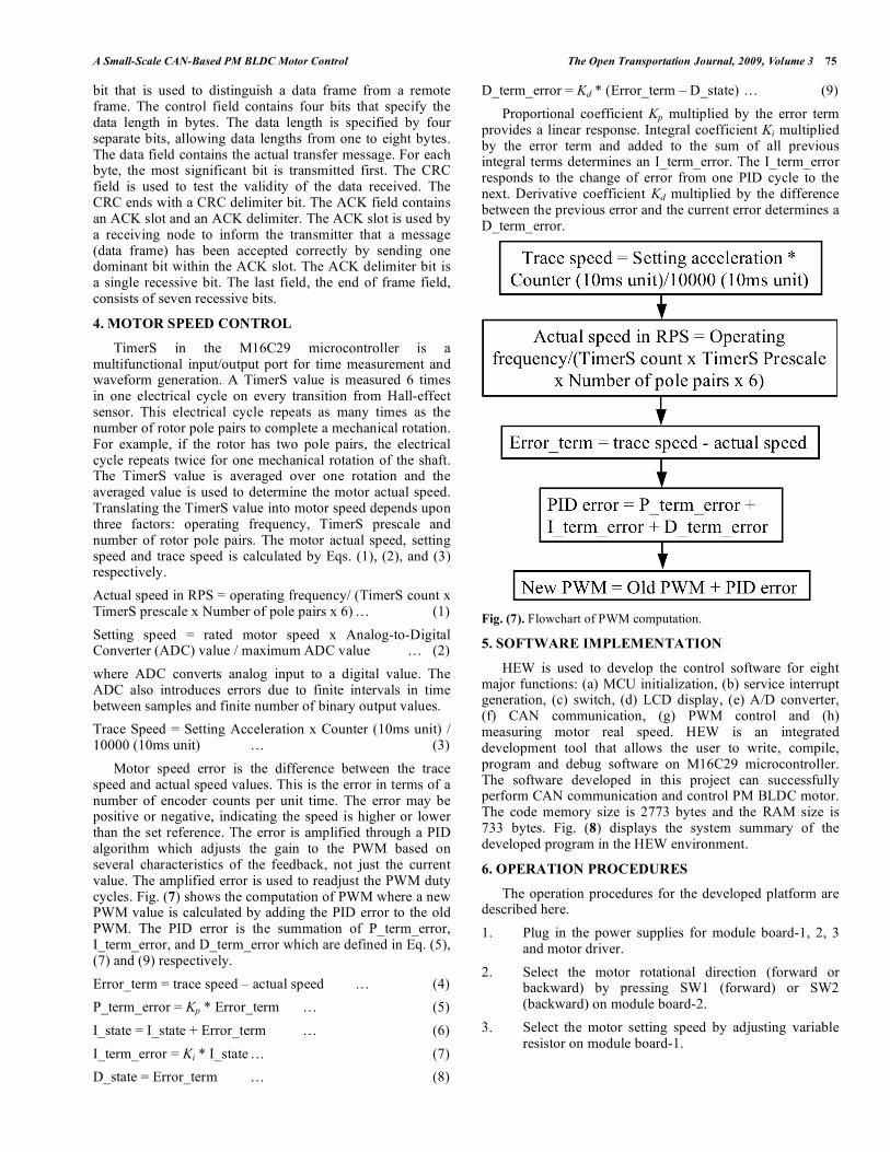
Motor speed error is the difference between the trace speed and actual speed values. This is the error in terms of a number of encoder counts per unit time. The error may be positive or negative, indicating the speed is higher or lower than the set reference. The error is amplified through a PID algorithm which adjusts the gain to the PWM based on several characteristics of the feedback, not just the current value. The amplified error is used to readjust the PWM duty cycles. Fig. (7) shows the computation of PWM where a new PWM value is calculated by adding the PID error to the old PWM. The PID error is the summation of P_term_error, I_term_error, and D_term_error which are defined in Eq. (5), (7) and (9) respectively.
Error_term = trace speed – actual speed … (4)
P_term_error = Kp * Error_term … (5)
I_state = I_state + Error_term … (6)
I_term_error = Ki * I_state … (7)
D_state = Error_term … (8)
D_term_error = Kd * (Error_term – D_state) … (9)
Proportional coefficient Kp multiplied by the error term provides a linear response. Integral coefficient Ki multiplied by the error term and added to the sum of all previous integral terms determines an I_term_error. The I_term_error responds to the change of error from one PID cycle to the next. Derivative coefficient Kd multiplied by the difference between the previous error and the current error determines a D_term_error.
Fig. (7). Flowchart of PWM computation.
5. SOFTWARE IMPLEMENTATION
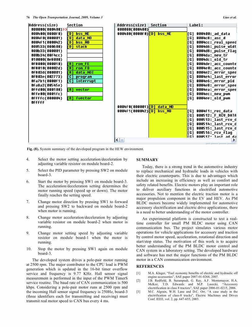
HEW is used to develop the control software for eight major functions: (a) MCU initialization, (b) service interrupt generation, (c) switch, (d) LCD display, (e) A/D converter, (f) CAN communication, (g) PWM control and (h) measuring motor real speed. HEW is an integrated development tool that allows the user to write, compile, program and debug software on M16C29 microcontroller. The software developed in this project can successfully perform CAN communication and control PM BLDC motor. The code memory size is 2773 bytes and the RAM size is 733 bytes. Fig. (8) displays the system summary of the developed program in the HEW environment.
6. OPERATION PROCEDURES
The operation procedures for the developed platform are described here.
1. Plug in the power supplies for module board-1, 2, 3 and motor driver.
2. Select the motor rotational direction (forward or backward) by pressing SW1 (forward) or SW2 (backward) on module board-2.
3. Select the motor setting speed by adjusting variable resistor on module board-1.
76 The Open Transportation Journal, 2009, Volume 3 Liao et al.
4. Select the motor setting acceleration/deceleration by adjusting variable resistor on module board-2.
5. Select the PID parameter by pressing SW2 on module board-3.
6. Start the motor by pressing SW1 on module board-3. The acceleration/deceleration setting determines the motor running speed (speed up or down). The motor finally reaches the setting speed.
7. Change motor direction by pressing SW1 to forward and pressing SW2 to backward on module board-2 when motor is running.
8. Change motor acceleration/deceleration by adjusting variable resistor on module board-2 when motor is running.
9. Change motor setting speed by adjusting variable resistor on module board-1 when the motor is running.
10. Stop the motor by pressing SW1 again on module board-3.
The developed system drives a pole-pair motor running at 2500 rpm. The major contributor to the CPU load is PWM generation which is updated in the 16-bit timer overflow service and frequency is 9.77 KHz. Hall sensor signal measurement is performed in the input of the PWM TimerS service routine. The baud rate of CAN communication is 500 kbps. Considering a pole-pair motor runs at 2500 rpm and the incoming Hall sensor signal frequency is 250Hz, board-3 (three identifiers each for transmitting and receiving) must transmit real motor speed to CAN bus every 4 ms.
SUMMARY
Today, there is a strong trend in the automotive industry to replace mechanical and hydraulic loads in vehicles with their electric counterparts. This is due to advantages which include an increasing in efficiency as well as comfort and safety related benefits. Electric motors play an important role to deliver auxiliary functions in electrified automotive accessories. Not to mention the electric traction motor is a major propulsion component in the EV and HEV. As PM BLDC motors become widely implemented for automotive accessory electrification and electric drive applications, there is a need to better understanding of the motor controller.
An experimental platform is constructed to test a real-time controller for small PM BLDC motor using CAN communication bus. The project simulates various motor operations for vehicle applications for accessory and traction by control motor speed, acceleration, rotational direction and start/stop status. The motivation of this work is to acquire better understanding of the PM BLDC motor control and CAN system in a laboratory setting. The developed hardware and software has met the major functions of the PM BLDC motor in a CAN communication environment.
REFERENCES
[1] M.A. Kluger, “Fuel economy benefits of electric and hydraulic off engine accessories”, SAE paper 2007-01-0268, 2007.
[2] J.B. Redfield, B. Surampudi, G. Ray, A.F. Montemayor, H.A. McKee, T.D. Edwards and M.P. Lasecki, “Accessory
electrification in class 8 tractors”, SAE paper 2006-01-0215, 2006. [3] M.C. Algrain, W.H. Lane and D.C. Orr, “A case study in the
electrification of class-8 trucks”, Electric Machines and Drives Conf. IEEE, vol. 2, pp. 647-655, 2003.
Fig. (8). System summary of the developed program in the HEW environment.
A Small-Scale CAN-Based PM BLDC Motor Control The Open Transportation Journal, 2009, Volume 3 77
[4] V.D. Mills and J.R. Wagner, “Behavioural modeling and analysis
of hybrid vehicle steering systems”, Proc. Inst. Mech. Engrs, J. Automobile Eng, vol. 217/D, pp. 349-361, 2003.
[5] M.M. Jamali, M.M. Brown, C.C. Sheh, C. Suriyakamol and M.Y. Niamat, “A CAN based real-time embedded system for DC motor
control”, SAE paper 2002-01-0444, 2002. [6] R.J. Vincent, T.J. Nehi, G. Gallegos-Lopez and M. Naidu, “High
capacity electric A/C compressor with integrated inverter for hybrid automotive and commercial vehicles”, SAE paper 2008-01-
02619, 2008. [7] A. Kabasawa and K. Takahashi, “Development of the IMA motor
for the V6 hybrid midsize sedan”, SAE paper 2005-01-0276, 2005. [8] J. Meisei, “An analytic foundation for the Toyota Prius THS-II
powertrain with a comparison to a strong parallel hybrid-electric powertrain”, SAE paper 2006-01-0666, 2006.
[9] N.C. Harris, T.M. Jahns and S. Huang, “Design of an integrated motor/controller drive for an automotive water pump application”,
Conference Record of the IEEE Industry Applications, 37th IAS Annual Meeting, vol. 3, pp. 2028-2035, 2002.
[10] F.L. Luo and H.G. Yeo, “Advanced PM brushless DC motor control and system for electric vehicles”, Industry Applications Conference,
IEEE, vol. 2, 2000, pp. 1336–1343. [11] P.J. McCleer, “Electric drives for pump, fan, and compressor loads
in automotive applications”, Proceedings of the IEEE International Symposium on Industrial Electronics, vol. 1, pp. 80-85, 1995.
[12] Robert Bosch GmbH, CAN Specification Version 2.0. ISO/TC22/
SC3/WG1 document 1992. [13] C.K. Chen, C.P. Hwang, and C.C. Su, “Implementation of a PC-
based ABS system with CAN-bus interface on an experimental platform”, Int. J. Vehicle Design, vol. 37/4, pp. 343-357, 2005.
[14] L. Xie, Q. Tian, and H. Ogai, “Virtual vehicle system development and its application for ABS design based on distributed network”,
Int. J. Comput. Appl. Technol., vol. 25/4, pp. 209-217, 2006. [15] J.D. Lee and B. H. Kantowitz, “Network analysis of information
flows to integrate in-vehicle information systems”, Int. J. Vehicle Inf. Commun. Syst., vol. 1/1, pp. 24-43, 2005.
[16] M. Ehsani, Y. Gao, S.E. Gay, and A. Emadi, Modern Electric, Hybrid Electric, and Fuel Cell Vehicles: Fundamentals, Theory,
and Design. USA: CRC Press, Boca Raton, FL 33487, pp. 199-201, 2004.
[17] Anaheim Automation, www.anaheimautomation.com/brushless-dc-motor-products.aspx/. Accessed March 30, 2009.
[18] Renesas, Renesas Starter Kit, RSK M16C29 User’s Manual, rev. 1.0, Renesas Technology Ltd., www.renesas.com, 2006.
[19] Renesas, Renesas Application Note – M16C29 Groups, rev. 3.0, Renesas Technology Ltd., www.renesas.com, 2005.
[20] TelCom Semiconductor, Inc. www.datasheetcatalog.com Accessed March 30, 2009.
Received: October 24, 2008 Revised: February 3, 2009 Accepted: February 9, 2009
© Liao et al.; Licensee Bentham Open.
This is an open access article licensed under the terms of the Creative Commons Attribution Non-Commercial License (http://creativecommons.org/licenses/by-nc/3.0/) which permits unrestricted, non-commercial use, distribution and reproduction in any medium, provided the work is properly cited.