Embed Size (px)
DESCRIPTION
Linix Motor Datasheet
Citation preview
BLDC Sensorless Reference Design UsingMC56F8006
Devices Supported:
MC56F8006
Document Number: DRM108Rev. 0
04/2009
How to Reach Us:
Home Page:www.freescale.com
E-mail:[email protected]
USA/Europe or Locations Not Listed:Freescale SemiconductorTechnical Information Center, CH3701300 N. Alma School RoadChandler, Arizona 85224+1-800-521-6274 or [email protected]
Europe, Middle East, and Africa:Freescale Halbleiter Deutschland GmbHTechnical Information CenterSchatzbogen 781829 Muenchen, Germany+44 1296 380 456 (English)+46 8 52200080 (English)+49 89 92103 559 (German)+33 1 69 35 48 48 (French)[email protected]
Japan:Freescale Semiconductor Japan Ltd.HeadquartersARCO Tower 15F1-8-1, Shimo-Meguro, Meguro-ku,Tokyo 153-0064, Japan0120 191014 or +81 3 5437 [email protected]
Asia/Pacific:Freescale Semiconductor China Ltd.Exchange Building 23FNo. 118 Jianguo RoadChaoyang DistrictBeijing 100022 China +86 10 5879 [email protected]
For Literature Requests Only:Freescale Semiconductor Literature Distribution Center1-800-441-2447 or 303-675-2140Fax: [email protected]
Information in this document is provided solely to enable system and software implementers to use Freescale Semiconductor products. There are no express or implied copyright licenses granted hereunder to design or fabricate any integrated circuits or integrated circuits based on the information in this document.
Freescale Semiconductor reserves the right to make changes without further notice to any products herein. Freescale Semiconductor makes no warranty, representation or guarantee regarding the suitability of its products for any particular purpose, nor does Freescale Semiconductor assume any liability arising out of the application or use of any product or circuit, and specifically disclaims any and all liability, including without limitation consequential or incidental damages. “Typical” parameters that may be provided in Freescale Semiconductor data sheets and/or specifications can and do vary in different applications and actual performance may vary over time. All operating parameters, including “Typicals”, must be validated for each customer application by customer’s technical experts. Freescale Semiconductor does not convey any license under its patent rights nor the rights of others. Freescale Semiconductor products are not designed, intended, or authorized for use as components in systems intended for surgical implant into the body, or other applications intended to support or sustain life, or for any other application in which the failure of the Freescale Semiconductor product could create a situation where personal injury or death may occur. Should Buyer purchase or use Freescale Semiconductor products for any such unintended or unauthorized application, Buyer shall indemnify and hold Freescale Semiconductor and its officers, employees, subsidiaries, affiliates, and distributors harmless against all claims, costs, damages, and expenses, and reasonable attorney fees arising out of, directly or indirectly, any claim of personal injury or death associated with such unintended or unauthorized use, even if such claim alleges that Freescale Semiconductor was negligent regarding the design or manufacture of the part.
Freescale™ and the Freescale logo are trademarks of Freescale Semiconductor, Inc. The ARM POWERED logo is a registered trademark of ARM Limited. ARM7TDMI-S is a trademark of ARM Limited.Java and all other Java-based marks are trademarks or registeredtrademarks of Sun Microsystems, Inc. in the U.S. and other countries.The PowerPC name is a trademark of IBM Corp. and is used under license.The described product contains a PowerPC processor core. The PowerPC name is a trademark of IBM Corp. and used under license. The described product is a PowerPC microprocessor. The PowerPC name is a trademark of IBM Corp. and is used under license. The described product is a PowerPC microprocessor core. The PowerPC name is a trademark of IBM Corp. and is used under license. All other product or service names are the property of their respective owners.
© Freescale Semiconductor, Inc. 2009. All rights reserved.
DRM108Rev. 004/2009
BLDC Sensorless Reference Design Using MC56F8006, Rev. 0
Freescale Semiconductor -1
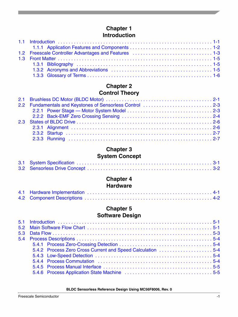
Chapter 1 Introduction
1.1 Introduction . . . . . . . . . . . . . . . . . . . . . . . . . . . . . . . . . . . . . . . . . . . . . . . . . . . . . . . . . . 1-11.1.1 Application Features and Components . . . . . . . . . . . . . . . . . . . . . . . . . . . . . . . 1-2
1.2 Freescale Controller Advantages and Features . . . . . . . . . . . . . . . . . . . . . . . . . . . . . . 1-31.3 Front Matter . . . . . . . . . . . . . . . . . . . . . . . . . . . . . . . . . . . . . . . . . . . . . . . . . . . . . . . . . . 1-5
1.3.1 Bibliography . . . . . . . . . . . . . . . . . . . . . . . . . . . . . . . . . . . . . . . . . . . . . . . . . . . 1-51.3.2 Acronyms and Abbreviations . . . . . . . . . . . . . . . . . . . . . . . . . . . . . . . . . . . . . . 1-51.3.3 Glossary of Terms . . . . . . . . . . . . . . . . . . . . . . . . . . . . . . . . . . . . . . . . . . . . . . . 1-6
Chapter 2 Control Theory
2.1 Brushless DC Motor (BLDC Motor) . . . . . . . . . . . . . . . . . . . . . . . . . . . . . . . . . . . . . . . . 2-12.2 Fundamentals and Keystones of Sensorless Control . . . . . . . . . . . . . . . . . . . . . . . . . . 2-3
2.2.1 Power Stage — Motor System Model . . . . . . . . . . . . . . . . . . . . . . . . . . . . . . . . 2-32.2.2 Back-EMF Zero Crossing Sensing . . . . . . . . . . . . . . . . . . . . . . . . . . . . . . . . . . 2-4
2.3 States of BLDC Drive . . . . . . . . . . . . . . . . . . . . . . . . . . . . . . . . . . . . . . . . . . . . . . . . . . . 2-62.3.1 Alignment . . . . . . . . . . . . . . . . . . . . . . . . . . . . . . . . . . . . . . . . . . . . . . . . . . . . . 2-62.3.2 Startup . . . . . . . . . . . . . . . . . . . . . . . . . . . . . . . . . . . . . . . . . . . . . . . . . . . . . . . 2-72.3.3 Running . . . . . . . . . . . . . . . . . . . . . . . . . . . . . . . . . . . . . . . . . . . . . . . . . . . . . . 2-7
Chapter 3 System Concept
3.1 System Specification . . . . . . . . . . . . . . . . . . . . . . . . . . . . . . . . . . . . . . . . . . . . . . . . . . . 3-13.2 Sensorless Drive Concept . . . . . . . . . . . . . . . . . . . . . . . . . . . . . . . . . . . . . . . . . . . . . . . 3-2
Chapter 4 Hardware
4.1 Hardware Implementation . . . . . . . . . . . . . . . . . . . . . . . . . . . . . . . . . . . . . . . . . . . . . . . 4-14.2 Component Descriptions . . . . . . . . . . . . . . . . . . . . . . . . . . . . . . . . . . . . . . . . . . . . . . . . 4-2
Chapter 5 Software Design
5.1 Introduction . . . . . . . . . . . . . . . . . . . . . . . . . . . . . . . . . . . . . . . . . . . . . . . . . . . . . . . . . . 5-15.2 Main Software Flow Chart . . . . . . . . . . . . . . . . . . . . . . . . . . . . . . . . . . . . . . . . . . . . . . . 5-15.3 Data Flow . . . . . . . . . . . . . . . . . . . . . . . . . . . . . . . . . . . . . . . . . . . . . . . . . . . . . . . . . . . . 5-35.4 Process Descriptions . . . . . . . . . . . . . . . . . . . . . . . . . . . . . . . . . . . . . . . . . . . . . . . . . . . 5-4
5.4.1 Process Zero-Crossing Detection . . . . . . . . . . . . . . . . . . . . . . . . . . . . . . . . . . . 5-45.4.2 Process Zero Cross Current and Speed Calculation . . . . . . . . . . . . . . . . . . . . 5-45.4.3 Low-Speed Detection . . . . . . . . . . . . . . . . . . . . . . . . . . . . . . . . . . . . . . . . . . . . 5-45.4.4 Process Commutation . . . . . . . . . . . . . . . . . . . . . . . . . . . . . . . . . . . . . . . . . . . 5-45.4.5 Process Manual Interface . . . . . . . . . . . . . . . . . . . . . . . . . . . . . . . . . . . . . . . . . 5-55.4.6 Process Application State Machine . . . . . . . . . . . . . . . . . . . . . . . . . . . . . . . . . 5-5
BLDC Sensorless Reference Design Using MC56F8006, Rev. 0
Freescale Semiconductor -2
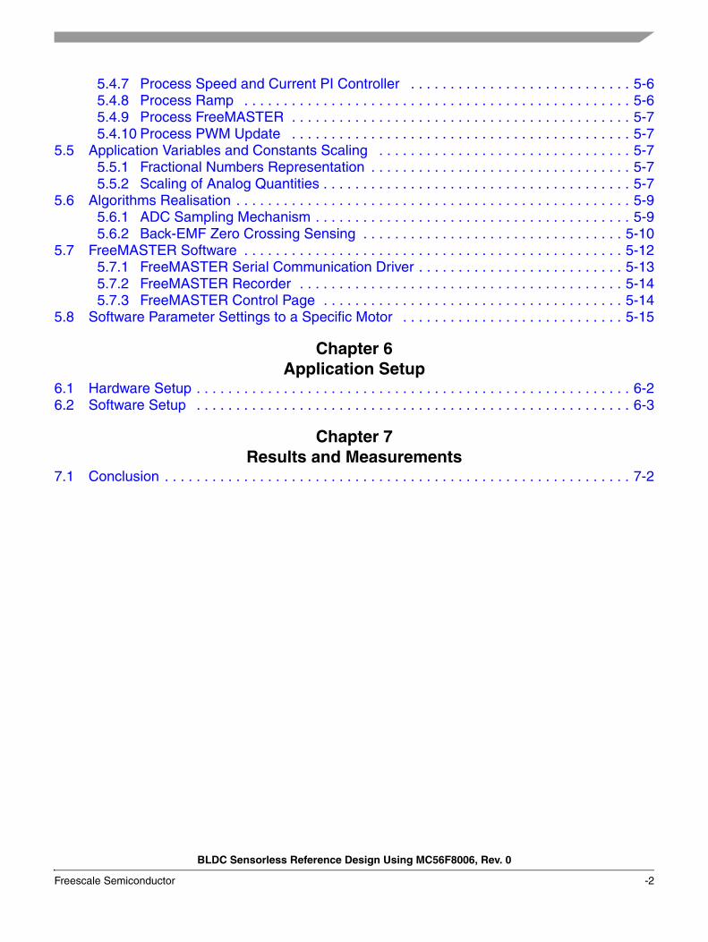
5.4.7 Process Speed and Current PI Controller . . . . . . . . . . . . . . . . . . . . . . . . . . . . 5-65.4.8 Process Ramp . . . . . . . . . . . . . . . . . . . . . . . . . . . . . . . . . . . . . . . . . . . . . . . . . 5-65.4.9 Process FreeMASTER . . . . . . . . . . . . . . . . . . . . . . . . . . . . . . . . . . . . . . . . . . . 5-75.4.10 Process PWM Update . . . . . . . . . . . . . . . . . . . . . . . . . . . . . . . . . . . . . . . . . . . 5-7
5.5 Application Variables and Constants Scaling . . . . . . . . . . . . . . . . . . . . . . . . . . . . . . . . 5-75.5.1 Fractional Numbers Representation . . . . . . . . . . . . . . . . . . . . . . . . . . . . . . . . . 5-75.5.2 Scaling of Analog Quantities . . . . . . . . . . . . . . . . . . . . . . . . . . . . . . . . . . . . . . . 5-7
5.6 Algorithms Realisation . . . . . . . . . . . . . . . . . . . . . . . . . . . . . . . . . . . . . . . . . . . . . . . . . . 5-95.6.1 ADC Sampling Mechanism . . . . . . . . . . . . . . . . . . . . . . . . . . . . . . . . . . . . . . . . 5-95.6.2 Back-EMF Zero Crossing Sensing . . . . . . . . . . . . . . . . . . . . . . . . . . . . . . . . . 5-10
5.7 FreeMASTER Software . . . . . . . . . . . . . . . . . . . . . . . . . . . . . . . . . . . . . . . . . . . . . . . . 5-125.7.1 FreeMASTER Serial Communication Driver . . . . . . . . . . . . . . . . . . . . . . . . . . 5-135.7.2 FreeMASTER Recorder . . . . . . . . . . . . . . . . . . . . . . . . . . . . . . . . . . . . . . . . . 5-145.7.3 FreeMASTER Control Page . . . . . . . . . . . . . . . . . . . . . . . . . . . . . . . . . . . . . . 5-14
5.8 Software Parameter Settings to a Specific Motor . . . . . . . . . . . . . . . . . . . . . . . . . . . . 5-15
Chapter 6 Application Setup
6.1 Hardware Setup . . . . . . . . . . . . . . . . . . . . . . . . . . . . . . . . . . . . . . . . . . . . . . . . . . . . . . . 6-26.2 Software Setup . . . . . . . . . . . . . . . . . . . . . . . . . . . . . . . . . . . . . . . . . . . . . . . . . . . . . . . 6-3
Chapter 7 Results and Measurements
7.1 Conclusion . . . . . . . . . . . . . . . . . . . . . . . . . . . . . . . . . . . . . . . . . . . . . . . . . . . . . . . . . . . 7-2

BLDC Sensorless Reference Design Using MC56F8006, Rev. 0
Freescale Semiconductor -3

BLDC Sensorless Reference Design Using MC56F8006, Rev. 0
-4 Freescale Semiconductor
BLDC Sensorless Reference Design Using MC56F8006, Rev. 0
Freescale Semiconductor 1-1
Chapter 1 Introduction
1.1 IntroductionThis design reference manual describes the design of a sensorless 3-phase brushless DC (BLDC) motor drive based on Freescale’s MC56F8006 dedicated motor-control device.
BLDC motors are very popular in a wide application area. The BLDC motor lacks a commutator, and is therefore more reliable than the DC motor. The BLDC motor also has advantages when compared to an AC induction motor. Since it achieves a higher efficiency by generating the rotor magnetic flux with rotor magnets, a BLDC motor is used in high-end white goods (such as refrigerators, washing machines, dishwashers), high-end pumps, fans, and in other appliances that require high reliability and efficiency.
The concept of the application is a speed and current control closed-loop BLDC drive using a sensorless zero crossing technique. To control the BLDC motor, the rotor position must be known at certain angles in order to align the applied voltage with the Back-EMF, which is induced in the stator winding due to the movement of the permanent magnets on the rotor.
Although some BLDC drives use sensors for position sensing, there is a trend to use sensorless control. The position is then evaluated from voltage or current flowing to the motor. One of the sensorless techniques is sensorless BLDC control with Back-EMF (electromotive force) zero-crossing sensing.
The advantages of this control are:• It saves costs on position sensors and wiring.• It can be used everywhere, where it is impossible or expensive to make additional connections
between position sensors and the control unit.• Low-cost system (medium demand for controlling DSP power).
It serves as an example of a BLDC motor-control design using the Freescale MC56F8006 Digital Signal Controller. This reference design includes basic motor theory, system design concept, hardware implementation, and software design including the FreeMASTER software visualisation tool.
Introduction
BLDC Sensorless Reference Design Using MC56F8006, Rev. 0
1-2 Freescale Semiconductor
1.1.1 Application Features and Components
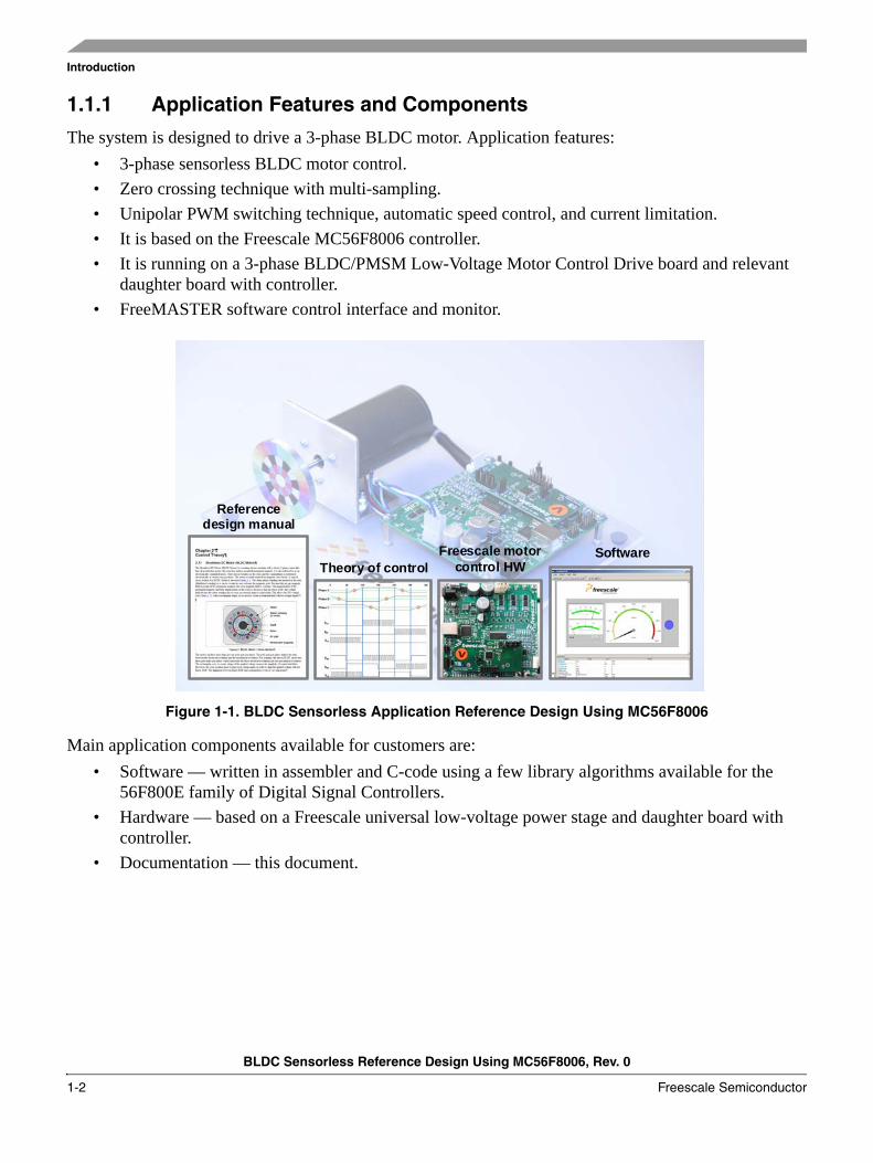
The system is designed to drive a 3-phase BLDC motor. Application features:• 3-phase sensorless BLDC motor control.• Zero crossing technique with multi-sampling.• Unipolar PWM switching technique, automatic speed control, and current limitation.• It is based on the Freescale MC56F8006 controller.• It is running on a 3-phase BLDC/PMSM Low-Voltage Motor Control Drive board and relevant
daughter board with controller.• FreeMASTER software control interface and monitor.
Figure 1-1. BLDC Sensorless Application Reference Design Using MC56F8006
Main application components available for customers are:• Software — written in assembler and C-code using a few library algorithms available for the
56F800E family of Digital Signal Controllers.• Hardware — based on a Freescale universal low-voltage power stage and daughter board with
controller.• Documentation — this document.
Reference design manual
Theory of controlFreescale motor
control HWSoftware
Introduction
BLDC Sensorless Reference Design Using MC56F8006, Rev. 0
Freescale Semiconductor 1-3
1.2 Freescale Controller Advantages and FeaturesThe 56F8002/56F8006 is a member of the 56800E core-based family of Digital Signal Controllers (DSCs). It combines the processing power of a DSP and the functionality of a microcontroller in a single chip with a flexible set of peripherals to create an extremely cost-effective solution. Because of its low cost, configuration flexibility, and compact program code, the 56F8002/56F8006 is well-suited for many applications.
The 56F8002/56F8006 provides the following features:• Up to 32 MIPS at 32 MHz core frequency.• DSP and MCU functionality in a unified, C-efficient architecture.• Program Flash 56F8002: 12 KB (6 K × 16) 56F8006: 16 KB (8 K × 16).• 2 KB (2 K × 16) Unified Data/Program RAM.• One 6-channel PWM module with PWM outputs, fault inputs, fault-tolerant design with dead time
insertion, supporting both center-aligned, and edge-aligned modes.• Two 14-channel 12-bit Analog-to-Digital Converters (ADCs) with single or continuous
conversion, configurable sample time and conversion speed/power, conversion complete flag and interrupt, input clock select from four sources, selectable asynchronous hardware conversion trigger, temperature sensor, and many more.
• Two Programmable Gain Amplifiers (PGA) with gain up to 32×.• Three Analog Comparators.• One Programmable Interval Timer (PIT).• One Serial Communication Interface (SCI) with LIN slave functionality.• One Serial Peripheral Interface (SPI).• One 16-bit Dual Timer (2 × 16-bit timers).• One Programmable Delay Block (PDB).• One Inter-Integrated Circuit (I2C) port.• One Real-Time Counter (RTC).• Computer Operating Properly (COP)/Watchdog.• Two On-Chip Relaxation Oscillators — 1 MHz and 8 MHz.• Crystal Oscillator.• Integrated Power-On Reset (POR) and Low-Voltage.• Interrupt (LVI) Module.• JTAG/Enhanced On-Chip Emulation (OnCE™) for unobtrusive, real-time debugging.
Introduction
BLDC Sensorless Reference Design Using MC56F8006, Rev. 0
1-4 Freescale Semiconductor
The sensorless BLDC control with unipolar switching and Back-EMF multi-sampling benefits greatly from the flexible PWM module, fast ADC, and Dual Timer module.
PWM offers flexibility in its configuration, enabling efficient 3-phase motor control. The PWM reload SYNC signal is generated to provide synchronization with other modules (Dual Timer, ADC, PDB).
The application uses the ADC block in software one-shot mode. The start of conversion, selection, and storage of ADC channels is carried out in a Dual Timer fast interrupt procedure, which is internally synchronized with the PWM reload SYNC signal. The ADC is used for evaluation of Back-EMF zero-crossing detection without any external comparators, and for sensing other analog quantities that are necessary for BLDC motor control.
The Dual Timer is an extremely flexible module, providing all required services relating to time events. It has the following features:
• Two 16-bit counters/timers.• Count up/down.• Counters are cascadable.• Programmable count modulus.• Maximum count rate equal to the peripheral clock/2, when counting external events.• Maximum count rate equal to the peripheral clock/1, when using internal clocks.• Count once or repeatedly.• Counters are pre-loadable.• Counters can share available input pins.• Each counter has a separate pre-scaler.• Each counter has capture and compare capability.
The application uses both channels of the Dual Timer:• First channel for multi-sampling operations and on-line Zero Crossing evaluation.• Second channel for commutation-event accomplishment.
Introduction
BLDC Sensorless Reference Design Using MC56F8006, Rev. 0
Freescale Semiconductor 1-5
1.3 Front Matter
1.3.1 Bibliography1. 56F8006 Data Sheet, MC56F8006, Freescale Semiconductor, 20082. Design of Brushless Permanent-magnet Motors, J.R. Hendershot JR and T.J.E. Miller, Magna
Physics Publishing and Clarendon Press, 19943. Sensorless Vector and Direct Torque Control, P. Vas (1998), Oxford University Press, ISBN
0-19-856465-1, New York.4. Sensorless BLDC Motor Control Using the MC68HC908MR32, DRM028/D, Motorola 20035. 3-phase BLDC Motor Control with Sensorless Back-EMF ADC Zero Crossing Detection using
DSP 56F80x, AN1913, Freescale 20056. CodeWarrior™ Development Studio for Freescale™ 56800/E Digital Signal Controllers,
Freescale Semiconductor, 20067. 3-Phase BLDC Motor Sensorless Control Using MC56F8013, DRM70, Freescale 20058. Free Master Software Users Manual, Freescale Semiconductor, 2004
For a current list of documentation, go to www.freescale.com.
1.3.2 Acronyms and Abbreviations
Table 1-1 contains sample acronyms and abbreviations used in this document.Table 1-1. Acronyms and Abbreviated Terms
Term Meaning
ADC Analog-to-digital converter.
Back-EMF Back electromagnetic force, induced voltage.
BLDC Brushless direct current motor.
DC Direct current.
DSC Digital signal controller.
GPIO General purpose input/output.
I/O Input/output interfaces between a computer system and the external world. A CPU reads an input to sense the level of an external signal and writes to an output to change the level of an external signal.
JTAG Joint test action group: acronym commonly used to refer to an interface allowing on-chip emulation and programming.
LED Light-emitting diode.
MC56F80x A Freescale family of 16-bit DSCs dedicated to motor control.
PI controller Proportional-integral controller.
PWM Pulse width modulation.
RPM Revolutions per minute.
SCI Serial communication interface module: a module that supports asynchronous communication.
Introduction
BLDC Sensorless Reference Design Using MC56F8006, Rev. 0
1-6 Freescale Semiconductor
1.3.3 Glossary of Terms
Table 1-2 shows a glossary of terms used in this document.Table 1-2. Glossary
Term Definition
Brush A component transferring electrical power from non-rotational terminals mounted on the stator to the rotor.
Commutator A mechanical device alternating DC current in a DC commutator motor and providing rotation of commutator motor.
Duty cycle The ratio of the amount of time the signal is on to the time it is off. Duty cycle is usually quoted as a percentage.
Hall sensor A position sensor giving six defined events (each 60 electrical degrees) per electrical revolution (for a 3-phase motor).
Interrupt A temporary break in the sequential execution of a program to respond to signals from peripheral devices by executing a subroutine.
PI controller Proportional-integral controller.
Quick start Software set of algorithms and drivers including graphical configuration tool for DSC/CPU initialization.
Reset To force a device to a known condition.
Software Instructions and data that control the operation of a microcontroller.
BLDC Sensorless Reference Design Using MC56F8006, Rev. 0
Freescale Semiconductor 2-1
Chapter 2 Control Theory
2.1 Brushless DC Motor (BLDC Motor)
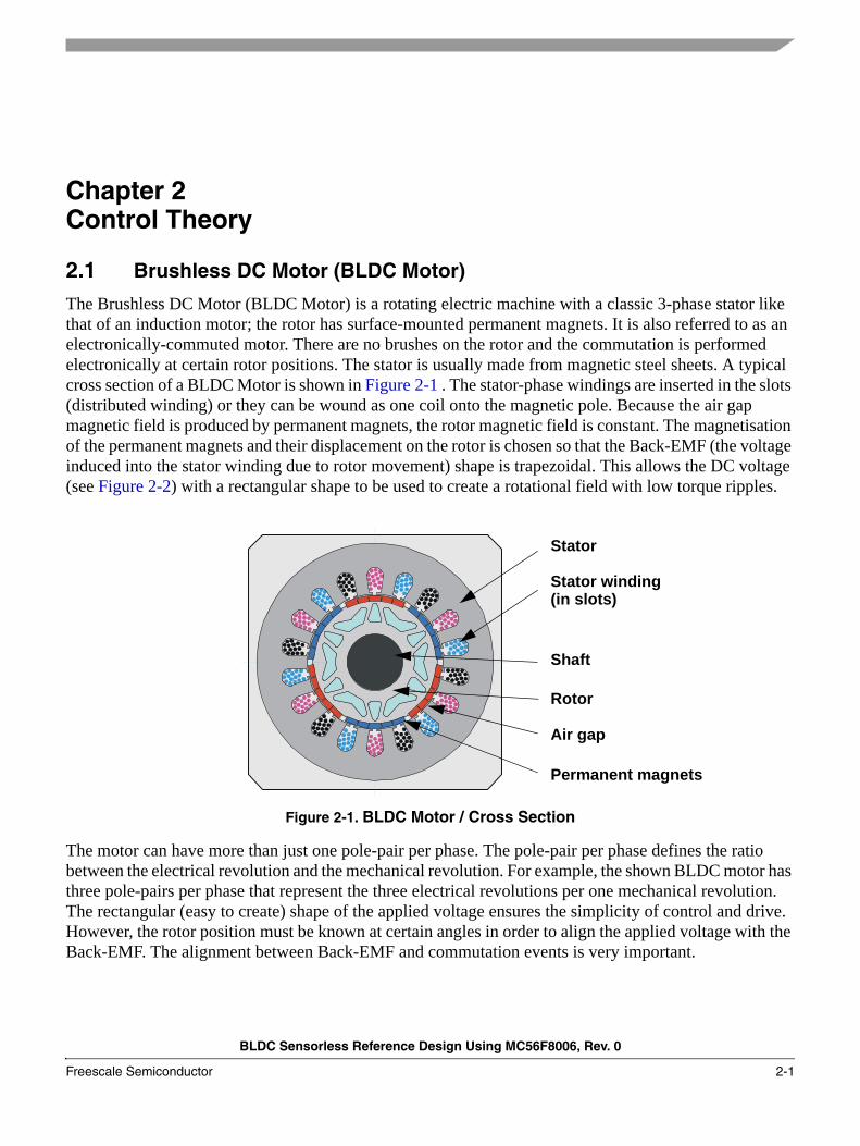
The Brushless DC Motor (BLDC Motor) is a rotating electric machine with a classic 3-phase stator like that of an induction motor; the rotor has surface-mounted permanent magnets. It is also referred to as an electronically-commuted motor. There are no brushes on the rotor and the commutation is performed electronically at certain rotor positions. The stator is usually made from magnetic steel sheets. A typical cross section of a BLDC Motor is shown in Figure 2-1 . The stator-phase windings are inserted in the slots (distributed winding) or they can be wound as one coil onto the magnetic pole. Because the air gap magnetic field is produced by permanent magnets, the rotor magnetic field is constant. The magnetisation of the permanent magnets and their displacement on the rotor is chosen so that the Back-EMF (the voltage induced into the stator winding due to rotor movement) shape is trapezoidal. This allows the DC voltage (see Figure 2-2) with a rectangular shape to be used to create a rotational field with low torque ripples.
Figure 2-1. BLDC Motor / Cross Section
The motor can have more than just one pole-pair per phase. The pole-pair per phase defines the ratio between the electrical revolution and the mechanical revolution. For example, the shown BLDC motor has three pole-pairs per phase that represent the three electrical revolutions per one mechanical revolution. The rectangular (easy to create) shape of the applied voltage ensures the simplicity of control and drive. However, the rotor position must be known at certain angles in order to align the applied voltage with the Back-EMF. The alignment between Back-EMF and commutation events is very important.
Stator
Stator winding(in slots)
Shaft
Rotor
Air gap
Permanent magnets
Control Theory
BLDC Sensorless Reference Design Using MC56F8006, Rev. 0
2-2 Freescale Semiconductor
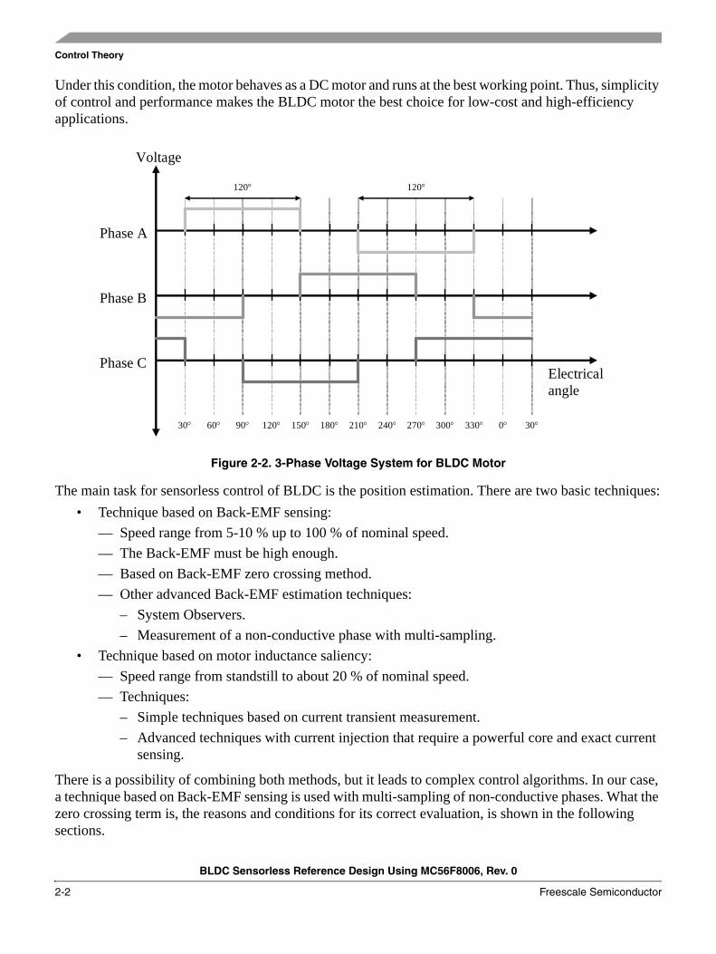
Under this condition, the motor behaves as a DC motor and runs at the best working point. Thus, simplicity of control and performance makes the BLDC motor the best choice for low-cost and high-efficiency applications.
Figure 2-2. 3-Phase Voltage System for BLDC Motor
The main task for sensorless control of BLDC is the position estimation. There are two basic techniques:• Technique based on Back-EMF sensing:
— Speed range from 5-10 % up to 100 % of nominal speed.— The Back-EMF must be high enough.— Based on Back-EMF zero crossing method.— Other advanced Back-EMF estimation techniques:
– System Observers.– Measurement of a non-conductive phase with multi-sampling.
• Technique based on motor inductance saliency:— Speed range from standstill to about 20 % of nominal speed.— Techniques:
– Simple techniques based on current transient measurement.– Advanced techniques with current injection that require a powerful core and exact current
sensing.
There is a possibility of combining both methods, but it leads to complex control algorithms. In our case, a technique based on Back-EMF sensing is used with multi-sampling of non-conductive phases. What the zero crossing term is, the reasons and conditions for its correct evaluation, is shown in the following sections.
Phase A
Phase B
Phase C
30° 60° 90° 120° 150° 180° 210° 240° 270° 300° 330° 0° 30°
Electrical angle
Voltage
120° 120°
Control Theory
BLDC Sensorless Reference Design Using MC56F8006, Rev. 0
Freescale Semiconductor 2-3
2.2 Fundamentals and Keystones of Sensorless ControlIn this section, fundamentals of sensorless control are described. This includes a power stage introduction, the BLDC motor model, reasons and conditions for Back-EMF zero crossing sensing.
2.2.1 Power Stage — Motor System Model
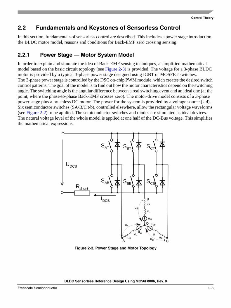
In order to explain and simulate the idea of Back-EMF sensing techniques, a simplified mathematical model based on the basic circuit topology (see Figure 2-3) is provided. The voltage for a 3-phase BLDC motor is provided by a typical 3-phase power stage designed using IGBT or MOSFET switches. The 3-phase power stage is controlled by the DSC on-chip PWM module, which creates the desired switch control patterns. The goal of the model is to find out how the motor characteristics depend on the switching angle. The switching angle is the angular difference between a real switching event and an ideal one (at the point, where the phase-to-phase Back-EMF crosses zero). The motor-drive model consists of a 3-phase power stage plus a brushless DC motor. The power for the system is provided by a voltage source (Ud). Six semiconductor switches (SA/B/C t/b), controlled elsewhere, allow the rectangular voltage waveforms (see Figure 2-2) to be applied. The semiconductor switches and diodes are simulated as ideal devices. The natural voltage level of the whole model is applied at one half of the DC-Bus voltage. This simplifies the mathematical expressions.
Figure 2-3. Power Stage and Motor Topology
Rshunt
IDCB
UDCB
SAT
SAB
SBT
SBB
SCT
SCB
Control Theory
BLDC Sensorless Reference Design Using MC56F8006, Rev. 0
2-4 Freescale Semiconductor
2.2.2 Back-EMF Zero Crossing Sensing
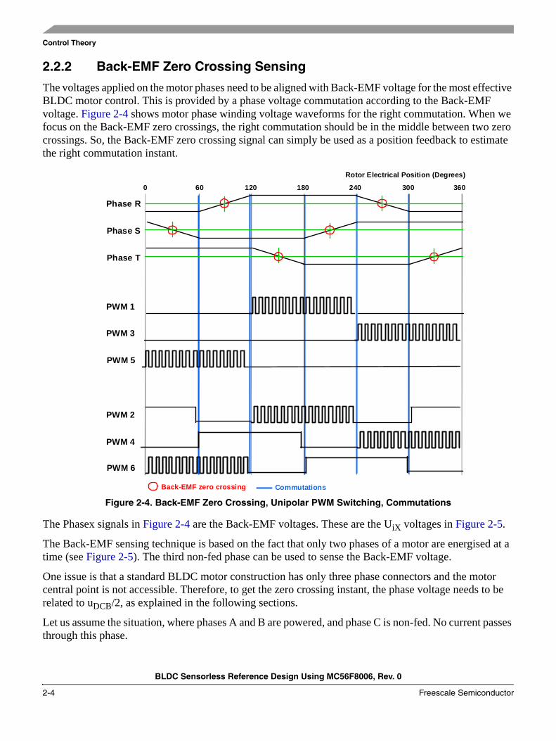
The voltages applied on the motor phases need to be aligned with Back-EMF voltage for the most effective BLDC motor control. This is provided by a phase voltage commutation according to the Back-EMF voltage. Figure 2-4 shows motor phase winding voltage waveforms for the right commutation. When we focus on the Back-EMF zero crossings, the right commutation should be in the middle between two zero crossings. So, the Back-EMF zero crossing signal can simply be used as a position feedback to estimate the right commutation instant.
Figure 2-4. Back-EMF Zero Crossing, Unipolar PWM Switching, Commutations
The Phasex signals in Figure 2-4 are the Back-EMF voltages. These are the UiX voltages in Figure 2-5.
The Back-EMF sensing technique is based on the fact that only two phases of a motor are energised at a time (see Figure 2-5). The third non-fed phase can be used to sense the Back-EMF voltage.
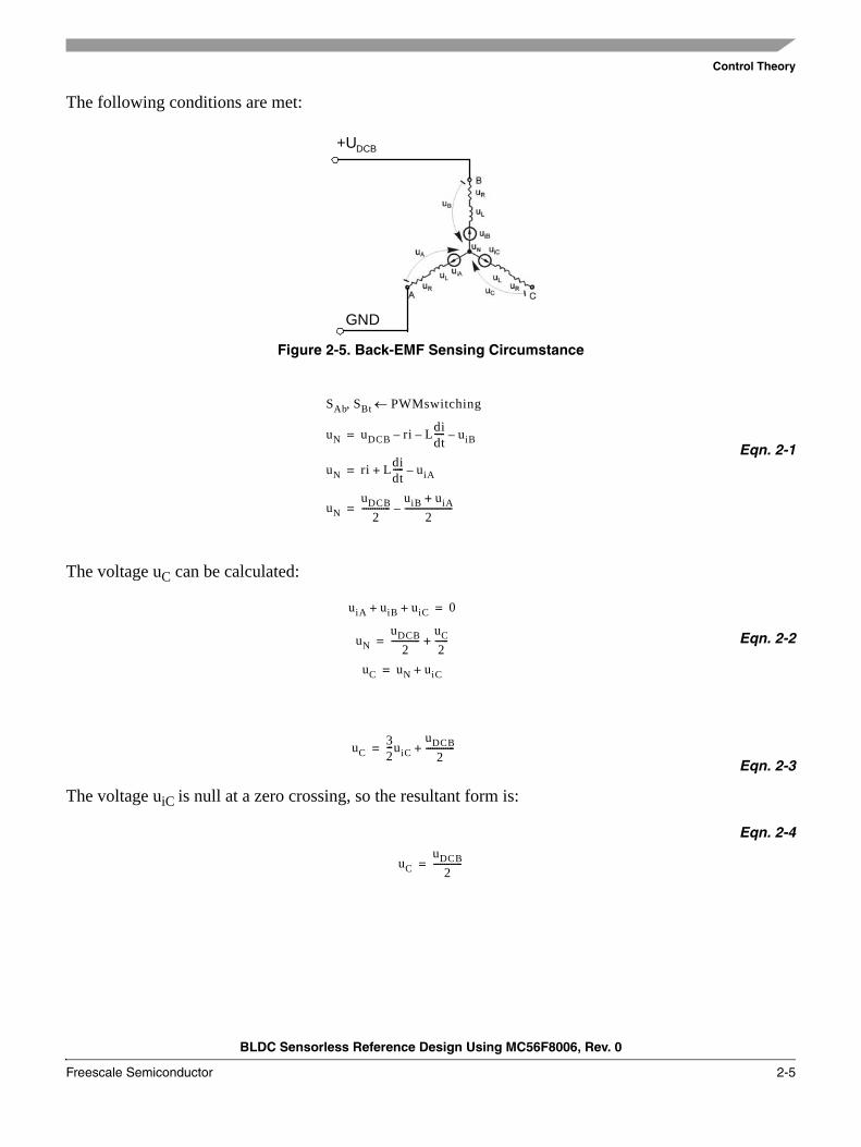
One issue is that a standard BLDC motor construction has only three phase connectors and the motor central point is not accessible. Therefore, to get the zero crossing instant, the phase voltage needs to be related to uDCB/2, as explained in the following sections.
Let us assume the situation, where phases A and B are powered, and phase C is non-fed. No current passes through this phase.
PWM 1
PWM 3
PWM 5
PWM 2
PWM 4
PWM 6
Phase R
Phase S
Phase T
0 60 120 180 240 300 360
Rotor Electrical Position (Degrees)
Back-EMF zero crossing Commutations
Control Theory
BLDC Sensorless Reference Design Using MC56F8006, Rev. 0
Freescale Semiconductor 2-5
The following conditions are met:
Figure 2-5. Back-EMF Sensing Circumstance
Eqn. 2-1
The voltage uC can be calculated:
Eqn. 2-2
Eqn. 2-3
The voltage uiC is null at a zero crossing, so the resultant form is:
Eqn. 2-4
+UDCB
GND
SAb SBt, PWMswitching←
uN uDCB ri– Ldidt-----– uiB–=
uN ri Ldidt----- uiA–+=
uNuDCB
2-------------
uiB uiA+
2----------------------–=
uiA uiB uiC+ + 0=
uNuDCB
2-------------
uC2------+=
uC uN uiC+=
uC32---uiC
uDCB2
-------------+=
uCuDCB
2-------------=
Control Theory
BLDC Sensorless Reference Design Using MC56F8006, Rev. 0
2-6 Freescale Semiconductor
2.3 States of BLDC DriveIn order to start and run the BLDC motor, the control algorithm has to go through the following states:
• Alignment (initial position setting)• Startup (forced commutations)• Running (sensorless running with Back-EMF acquisition and zero-crossing detection)
2.3.1 Alignment
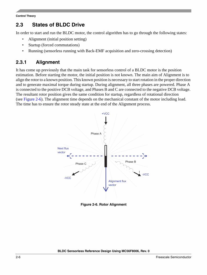
It has come up previously that the main task for sensorless control of a BLDC motor is the position estimation. Before starting the motor, the initial position is not known. The main aim of Alignment is to align the rotor to a known position. This known position is necessary to start rotation in the proper direction and to generate maximal torque during startup. During alignment, all three phases are powered. Phase A is connected to the positive DCB voltage, and Phases B and C are connected to the negative DCB voltage. The resultant rotor position gives the same condition for startup, regardless of rotational direction (see Figure 2-6). The alignment time depends on the mechanical constant of the motor including load. The time has to ensure the rotor steady state at the end of the Alignment process.
Figure 2-6. Rotor Alignment
Control Theory
BLDC Sensorless Reference Design Using MC56F8006, Rev. 0
Freescale Semiconductor 2-7
2.3.2 Startup
The Back-EMF technique can be used when the rotor is moving. The startup process ensures the initial rotor movement, followed by Back-EMF evaluation. The startup process starts immediatelly after the alignment process. The first flux vector applied on the motor is orthogonal to the alignment flux vector. The flux vector is applied for a period defined as a constant value during the drive tuning. The next five flux vectors follow in order to create a rotational field. The way to define a startup is to use a table with period timings. The initial period has to be tuned, based on load inertia.
The startup tuning is the most difficult task in the Back-EMF sensorless technique. The tuning difficulty depends on the load type. On a passive load, where the load torque starts at 0 Nm and grows with the motor speed, it is quite easy. A more difficult situation can be observed on drives that have non-zero starting torque or a variable torque within one revolution, such as compressors. If load inertia is variable, the number of starting flux vectors can be changed. A number smaller than six brings about a more robust startup at variable load inertia, however, a number less than three leads to an unreliable startup. In other cases, the six starting flux vectors (one electrical revolution) seem to be an optimal value. Once the last flux vector has executed, Back-EMF voltage evaluation is enabled and the motor enters the running (sensorless) mode.
2.3.3 Running
The running sensorless mode incorporates the Back-EMF acquisition with zero-crossing detection for the commutation control. In this mode the commutation instant is calculated according to the zero-crossing feedback as explained in Section 2.2.2, “Back-EMF Zero Crossing Sensing.”
Control Theory
BLDC Sensorless Reference Design Using MC56F8006, Rev. 0
2-8 Freescale Semiconductor
BLDC Sensorless Reference Design Using MC56F8006, Rev. 0
Freescale Semiconductor 3-1
Chapter 3 System Concept
3.1 System SpecificationThe motor-control system is designed to drive a 3-phase brushless DC motor in a speed and current closed-loop. The application meets the following performance specifications:
• It is targeted at the MC56F8006 (or 56F8002) Digital Signal Controller.• It is running on the 3-phase motor control drive universal low power board (24 V).• Control technique incorporating:
— Sensorless Brushless DC Motor Control with Back-EMF zero crossing sensing.— Closed-loop speed control with automatic current regulation and limitation.— Back-EMF multi-sampling method — 6 μs sampling period during PWM on-time.— Starting up with alignment, open-loop startup.— Full 4-quadrant operation.— Manual interface (Run / Stop switch, speed Up / Down push-button control).— FreeMASTER software control interface (motor run / stop, speed / current setup).— FreeMASTER software remote monitor.
System Concept
BLDC Sensorless Reference Design Using MC56F8006, Rev. 0
3-2 Freescale Semiconductor
3.2 Sensorless Drive ConceptThe chosen system concept is shown below. The system blocks are broadly described in the following section to outline presented sensorless design.
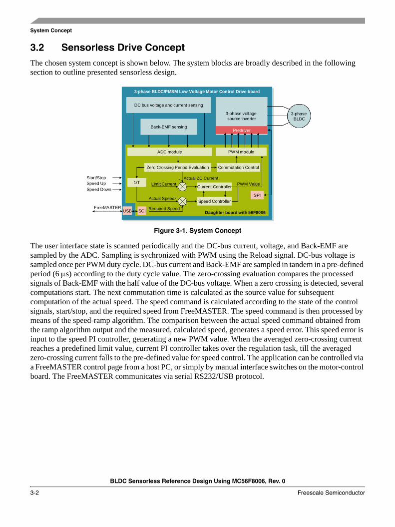
Figure 3-1. System Concept
The user interface state is scanned periodically and the DC-bus current, voltage, and Back-EMF are sampled by the ADC. Sampling is sychronized with PWM using the Reload signal. DC-bus voltage is sampled once per PWM duty cycle. DC-bus current and Back-EMF are sampled in tandem in a pre-defined period (6 μs) according to the duty cycle value. The zero-crossing evaluation compares the processed signals of Back-EMF with the half value of the DC-bus voltage. When a zero crossing is detected, several computations start. The next commutation time is calculated as the source value for subsequent computation of the actual speed. The speed command is calculated according to the state of the control signals, start/stop, and the required speed from FreeMASTER. The speed command is then processed by means of the speed-ramp algorithm. The comparison between the actual speed command obtained from the ramp algorithm output and the measured, calculated speed, generates a speed error. This speed error is input to the speed PI controller, generating a new PWM value. When the averaged zero-crossing current reaches a predefined limit value, current PI controller takes over the regulation task, till the averaged zero-crossing current falls to the pre-defined value for speed control. The application can be controlled via a FreeMASTER control page from a host PC, or simply by manual interface switches on the motor-control board. The FreeMASTER communicates via serial RS232/USB protocol.
3-phase BLDC/PMSM Low Voltage Motor Control Drive board
3-phase voltage source inverter
3-phase BLDC
Predriver
DC bus voltage and current sensing
Back-EMF sensing
PWM module
SPI
SCI
Zero Crossing Period Evaluation Commutation Control
1/T
ADC module
Current Controller
Speed Controller
Actual ZC CurrentLimit Current
Actual Speed
PWM Value
Required SpeedFreeMASTER
Start/StopSpeed UpSpeed Down
-
-
Daughter board with 56F8006USB
BLDC Sensorless Reference Design Using MC56F8006, Rev. 0
Freescale Semiconductor 4-1
Chapter 4 Hardware
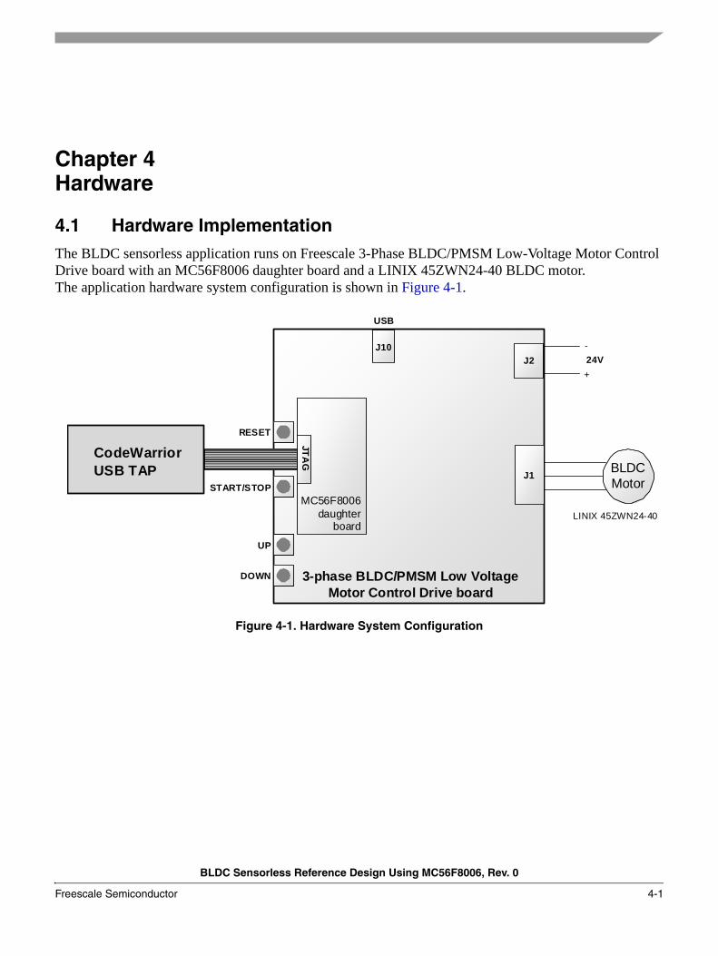
4.1 Hardware ImplementationThe BLDC sensorless application runs on Freescale 3-Phase BLDC/PMSM Low-Voltage Motor Control Drive board with an MC56F8006 daughter board and a LINIX 45ZWN24-40 BLDC motor. The application hardware system configuration is shown in Figure 4-1.
Figure 4-1. Hardware System Configuration
3-phase BLDC/PMSM Low Voltage Motor Control Drive board
BLDC Motor
+24V
CodeWarriorUSB TAP
LINIX 45ZWN24-40
JTAG
J10J2
J1
-
RESET
START/STOP
UP
DOWN
USB
MC56F8006 daughter
board
Hardware
BLDC Sensorless Reference Design Using MC56F8006, Rev. 0
4-2 Freescale Semiconductor
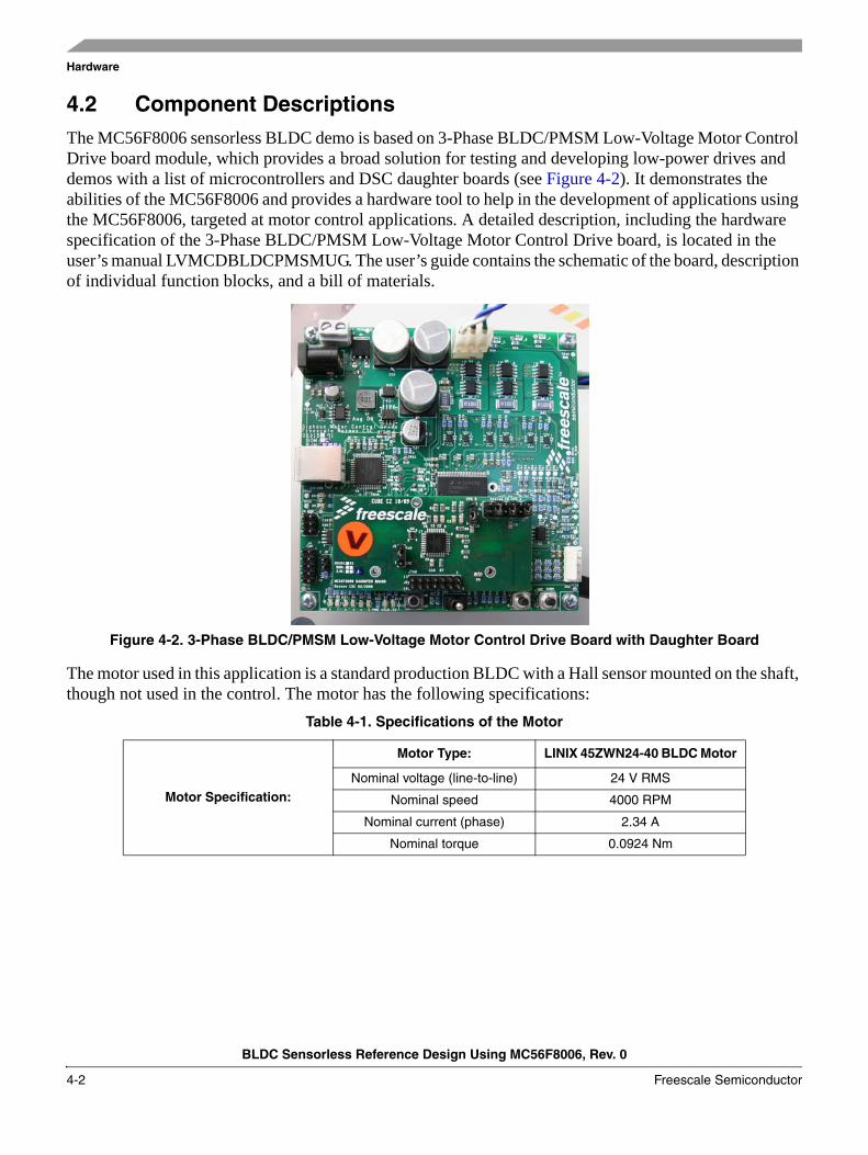
4.2 Component DescriptionsThe MC56F8006 sensorless BLDC demo is based on 3-Phase BLDC/PMSM Low-Voltage Motor Control Drive board module, which provides a broad solution for testing and developing low-power drives and demos with a list of microcontrollers and DSC daughter boards (see Figure 4-2). It demonstrates the abilities of the MC56F8006 and provides a hardware tool to help in the development of applications using the MC56F8006, targeted at motor control applications. A detailed description, including the hardware specification of the 3-Phase BLDC/PMSM Low-Voltage Motor Control Drive board, is located in the user’s manual LVMCDBLDCPMSMUG. The user’s guide contains the schematic of the board, description of individual function blocks, and a bill of materials.
Figure 4-2. 3-Phase BLDC/PMSM Low-Voltage Motor Control Drive Board with Daughter Board
The motor used in this application is a standard production BLDC with a Hall sensor mounted on the shaft, though not used in the control. The motor has the following specifications:
Table 4-1. Specifications of the Motor
Motor Specification:
Motor Type: LINIX 45ZWN24-40 BLDC Motor
Nominal voltage (line-to-line) 24 V RMS
Nominal speed 4000 RPM
Nominal current (phase) 2.34 A
Nominal torque 0.0924 Nm
BLDC Sensorless Reference Design Using MC56F8006, Rev. 0
Freescale Semiconductor 5-1
Chapter 5 Software Design
5.1 IntroductionThis section describes the design of the drive’s software blocks. The software description comprises these topics:
• Main Software Flow Chart• Data Flow
5.2 Main Software Flow ChartThe main software flow chart incorporates the main routine (background loop) entered from reset, and the interrupt events. The main routine includes the initialization of the microcontroller and the main loop.
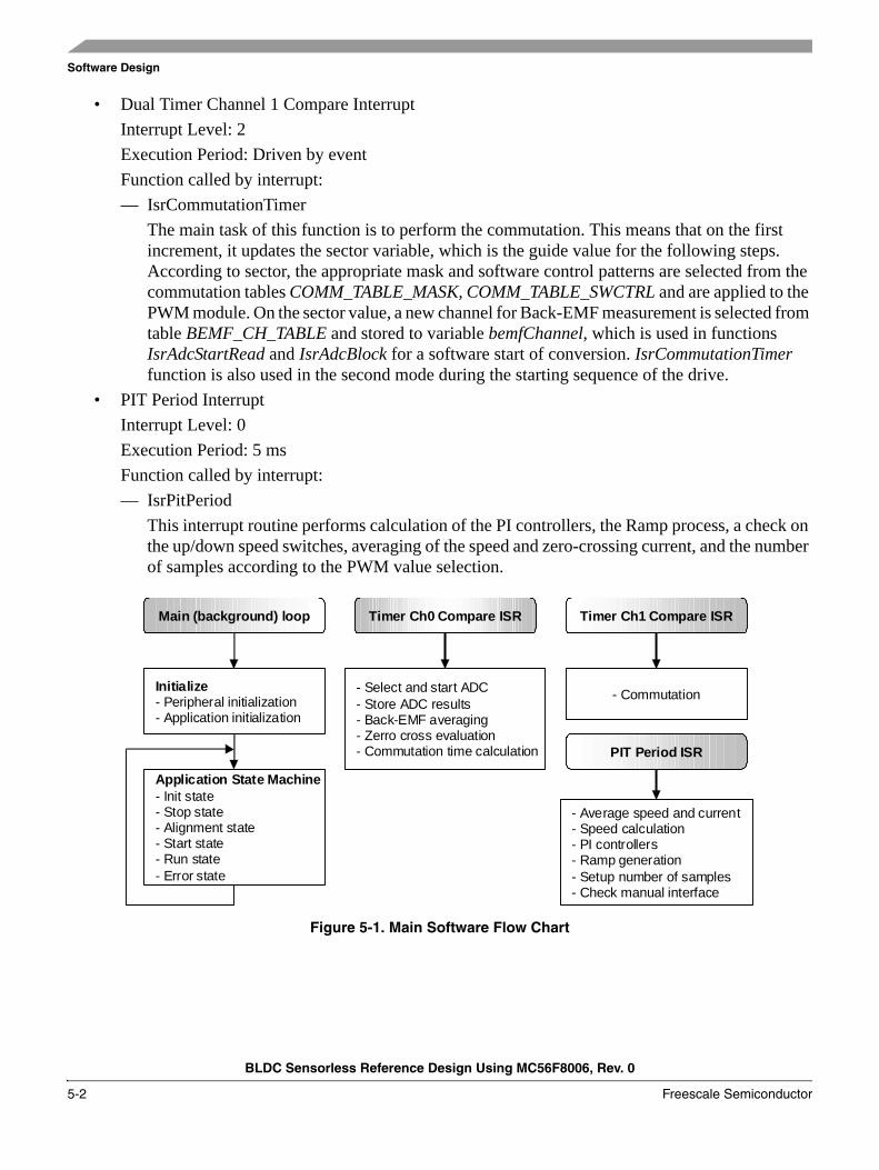
After initialization, the main routine enters an endless loop, which executes the application state machine consisting of init, stop, alignment, startup, run, and error states. The transition between the states depends on the state of the START/ STOP switch and the drive status. The main software flow chart is given in Figure 5-1. Apart from the background loop, the software incorporates the following three interrupts:
• Dual Timer Channel 0 Compare InterruptInterrupt Level: 2Execution Period: 6 μsFunctions called by interrupt:— IsrAdcStartRead
Fast interrupt routine, which performs a start conversion and reads the results of ADC. Physical quantities that are measured: three Back-EMF voltages with a two-sample averaging process, DC-bus voltage and DC-bus current. The next task of this function is the switching between ADC channels, first and last sample recognition, zero-crossing detection, and zero-crossing to commutation time calculation. When a zero crossing is detected, the actual value of iDcb is added to iDcbSum, zcToCmt time is added to periodSum, and the zero-crossing counter zcCnt is incremented for the next averaging process.
— IsrAdcBlockFast interrupt routine, which is launched after a commutation and performs the testing of the selected Back-EMF for 20-80 % of DC-bus voltage.
Software Design
BLDC Sensorless Reference Design Using MC56F8006, Rev. 0
5-2 Freescale Semiconductor
• Dual Timer Channel 1 Compare InterruptInterrupt Level: 2Execution Period: Driven by eventFunction called by interrupt:— IsrCommutationTimer
The main task of this function is to perform the commutation. This means that on the first increment, it updates the sector variable, which is the guide value for the following steps. According to sector, the appropriate mask and software control patterns are selected from the commutation tables COMM_TABLE_MASK, COMM_TABLE_SWCTRL and are applied to the PWM module. On the sector value, a new channel for Back-EMF measurement is selected from table BEMF_CH_TABLE and stored to variable bemfChannel, which is used in functions IsrAdcStartRead and IsrAdcBlock for a software start of conversion. IsrCommutationTimer function is also used in the second mode during the starting sequence of the drive.
• PIT Period InterruptInterrupt Level: 0Execution Period: 5 msFunction called by interrupt:— IsrPitPeriod
This interrupt routine performs calculation of the PI controllers, the Ramp process, a check on the up/down speed switches, averaging of the speed and zero-crossing current, and the number of samples according to the PWM value selection.
Figure 5-1. Main Software Flow Chart
Main (background) loop Timer Ch0 Compare ISR Timer Ch1 Compare ISR
Initialize- Peripheral initialization- Application initialization
- Select and start ADC- Store ADC results- Back-EMF averaging- Zerro cross evaluation- Commutation time calculation
- Commutation
Application State Machine- Init state- Stop state- Alignment state- Start state- Run state- Error state
PIT Period ISR
- Average speed and current- Speed calculation- PI controllers- Ramp generation- Setup number of samples- Check manual interface
Software Design
BLDC Sensorless Reference Design Using MC56F8006, Rev. 0
Freescale Semiconductor 5-3
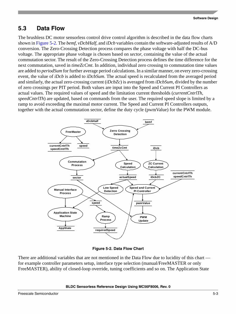
5.3 Data FlowThe brushless DC motor sensorless control drive control algorithm is described in the data flow charts shown in Figure 5-2. The bemf, vDcbHalf, and iDcb variables contain the software-adjusted results of A/D conversion. The Zero-Crossing Detection process compares the phase voltage with half the DC-bus voltage. The appropriate phase voltage is chosen based on sector, containing the value of the actual commutation sector. The result of the Zero-Crossing Detection process defines the time difference for the next commutation, saved in timeZcCmt. In addition, individual zero crossing to commutation time values are added to periodSum for further average period calculations. In a similar manner, on every zero-crossing event, the value of iDcb is added to iDcbSum. The actual speed is recalculated from the averaged period and similarly, the actual zero-crossing current (iDcbZc) is averaged from iDcbSum, divided by the number of zero crossings per PIT period. Both values are input into the Speed and Current PI Controllers as actual values. The required values of speed and the limitation current thresholds (currentCntrlTh, speedCntrlTh) are updated, based on commands from the user. The required speed slope is limited by a ramp to avoid exceeding the maximal motor current. The Speed and Current PI Controllers outputs, together with the actual commutation sector, define the duty cycle (pwmValue) for the PWM module.
Figure 5-2. Data Flow Chart
There are additional variables that are not mentioned in the Data Flow due to lucidity of this chart — for example controller parameters setup, interface type selection (manual/FreeMASTER or only FreeMASTER), ability of closed-loop override, tuning coefficients and so on. The Application State
vDcbHalf
Zerro CrossingDetection
SpeedCalculation
ZC CurrentCalculation
actualSpeed iDcbZC
Speed and CurrentPI Controller
Low SpeedDetection
CommutationProcess
timeZcCmt
sector
Manual InterfaceProcess
Application StateMachine Ramp
ProcessPWM
Update
FreeMaster
pwmValue
currentCntrlThspeedCntrlTh
iDcb
bemf
AppState
speed
requiredSpeed
speedcurrentCntrlThspeedCntrlTh

Software Design
BLDC Sensorless Reference Design Using MC56F8006, Rev. 0
5-4 Freescale Semiconductor
Machine sets its state AppState, based on inputs from the Manual Interface, Low-Speed Detection (Standstill), FreeMASTER interface, and other state variables not mentioned in the main Data Flow Chart.
5.4 Process DescriptionsThe main processes of the brushless DC motor sensorless drive application can also be seen in Figure 5-2.
5.4.1 Process Zero-Crossing Detection
This process is called every 6 μs when PWM is on. This process is in the IsrAdcStartRead interrupt. Prior to this process, A/D conversion of the selected channels is carried out, and also some basic software processing of the acquired samples. This means, firstly, an averaged value of the last and current samples of Back-EMF (bemf). The next important value for zero-crossing evaluation is the midpoint of the DC-bus voltage vDcbHalf. In reality, vDcbHalf is not exactly half the value, and can be tuned using the coefficient dcbHalfCoef. Then the averaged BEMF is compared to vDcbHalf and the transition is evaluated. The actual DC-bus current is also scanned in tandem with bemf, and its value is taken, when a zero-crossing event arises. The DC-bus current value at a zero crossing point is acceptably stable, and therefore suitable for the control process. If a zero crossing is detected, the new time event timeZcCmt is calculated — meaning the time from a zero crossing to the next commutation. Then it is added to periodSum, and likewise iDcb is added to iDcbSum, and the zero-crossing counter (zcCnt) is icremented for future averaged value calculations. A new commutation event is set in the commutation timer — Dual Timer Channel 1 — as the new compare event.
5.4.2 Process Zero Cross Current and Speed Calculation
Both current and period sums are averaged to get suitable input values to the Speed and Curent PI controllers. The averaging process calculates the results from a non-constant number of samples. Source values for averaging are both the sums and the zero-crossing counter zcCnt value. Then the averaged period is re-calculated as the motor speed. This process is executed every 5 ms in the IsrPitPeriod interrupt.
5.4.3 Low-Speed Detection
This process compares the re-calculated actual speed with the minimal speed. On an error, the motor is stopped, and then the startup sequence can be repeated. This process is executed every 5 ms in the IsrPitPeriod interrupt.
5.4.4 Process Commutation
This process updates the variable sector. PWM update based on the new commutation sector is performed in the PWM Update process. The commutation process is called on every new commutation event. So, the execution period depends on the motor speed.
Software Design
BLDC Sensorless Reference Design Using MC56F8006, Rev. 0
Freescale Semiconductor 5-5
5.4.5 Process Manual Interface
This process checks the state of the input pins, where the START/STOP switch and UP/DOWN buttons are connected. The processing of the of UP/DOWN buttons is executed every 5 ms in the IsrPitPeriod interrupt and START/STOP button in the Application State machine.
5.4.6 Process Application State Machine
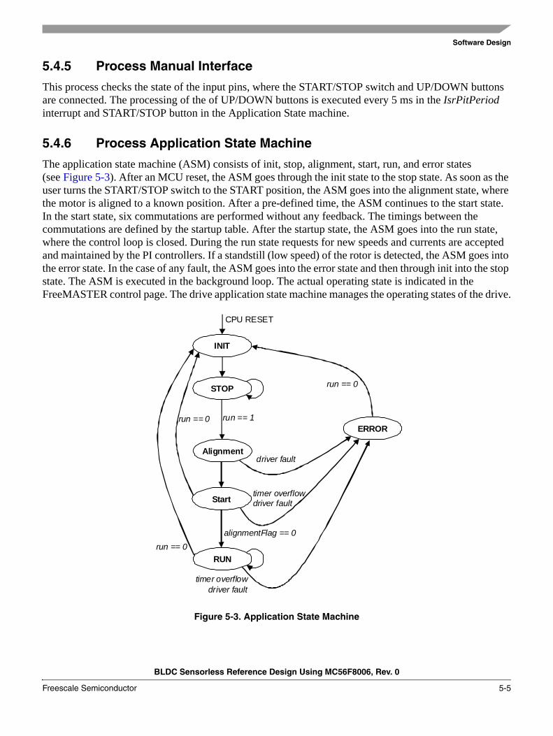
The application state machine (ASM) consists of init, stop, alignment, start, run, and error states (see Figure 5-3). After an MCU reset, the ASM goes through the init state to the stop state. As soon as the user turns the START/STOP switch to the START position, the ASM goes into the alignment state, where the motor is aligned to a known position. After a pre-defined time, the ASM continues to the start state. In the start state, six commutations are performed without any feedback. The timings between the commutations are defined by the startup table. After the startup state, the ASM goes into the run state, where the control loop is closed. During the run state requests for new speeds and currents are accepted and maintained by the PI controllers. If a standstill (low speed) of the rotor is detected, the ASM goes into the error state. In the case of any fault, the ASM goes into the error state and then through init into the stop state. The ASM is executed in the background loop. The actual operating state is indicated in the FreeMASTER control page. The drive application state machine manages the operating states of the drive.
Figure 5-3. Application State Machine
INIT
STOP
Alignment
Start
RUN
ERROR
CPU RESET
run == 1
driver fault
run == 0
timer overflowdriver fault
alignmentFlag == 0
timer overflowdriver fault
run == 0
run == 0
Software Design
BLDC Sensorless Reference Design Using MC56F8006, Rev. 0
5-6 Freescale Semiconductor
5.4.7 Process Speed and Current PI Controller
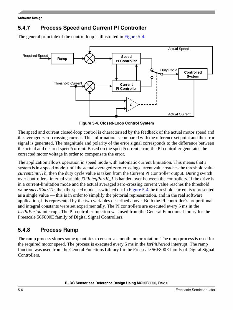
The general principle of the control loop is illustrated in Figure 5-4.
Figure 5-4. Closed-Loop Control System
The speed and current closed-loop control is characterised by the feedback of the actual motor speed and the averaged zero-crossing current. This information is compared with the reference set point and the error signal is generated. The magnitude and polarity of the error signal corresponds to the difference between the actual and desired speed/current. Based on the speed/current error, the PI controller generates the corrected motor voltage in order to compensate the error.
The application allows operation in speed mode with automatic current limitation. This means that a system is in a speed mode, until the actual averaged zero-crossing current value reaches the threshold value currentCntrlTh, then the duty cycle value is taken from the Current PI Controller output. During switch over controllers, internal variable f32IntegPartK_1 is handed over between the controllers. If the drive is in a current-limitation mode and the actual averaged zero-crossing current value reaches the threshold value speedCntrlTh, then the speed mode is switched on. In Figure 5-4 the threshold current is represented as a single value — this is in order to simplify the pictorial representation, and in the real software application, it is represented by the two variables described above. Both the PI controller´s proportional and integral constants were set experimentally. The PI controllers are executed every 5 ms in the IsrPitPeriod interrupt. The PI controller function was used from the General Functions Library for the Freescale 56F800E family of Digital Signal Controllers.
5.4.8 Process Ramp
The ramp process slopes some quantities to ensure a smooth motor rotation. The ramp process is used for the required motor speed. The process is executed every 5 ms in the IsrPitPeriod interrupt. The ramp function was used from the General Functions Library for the Freescale 56F800E family of Digital Signal Controllers.
Threshold Current
Ramp SpeedPI Controller
CurrentPI Controller
ControlledSystem
Actual Current
Actual Speed
C
Required Speed
Duty Cycle
Software Design
BLDC Sensorless Reference Design Using MC56F8006, Rev. 0
Freescale Semiconductor 5-7
5.4.9 Process FreeMASTER
The FreeMASTER process is not a part of the application software. FreeMASTER communication is implemented fully by the RS232 driver interface, so no additional software support is necessary to provide remote control. FreeMASTER writes new values directly into data RAM, where particular variables are located.
5.4.10 Process PWM Update
This process generates the correct voltage pattern on the motor, based on the actual sector and required output voltage. There are selected PWM outputs from the commutation tables to be masked and software controlled, based on the actual sector.
5.5 Application Variables and Constants Scaling
5.5.1 Fractional Numbers Representation
The sensorless PMSM vector control application uses a fractional representation for all real quantities, except time. The N-bit signed fractional format is represented using 1. [N-1] format (one sign bit, N-1 fractional bits). Signed fractional numbers (SF) are in the following range:
Eqn. 5-1
For words and long-word signed fractions, the most negative number that can be represented is −1.0, and the internal representation is 0x8000 and 0x80000000. The most positive word is 0x7FFF or 1.0 – 2-15 and the most positive long-word is 0x7FFFFFFF or 1.0 – 2-31.
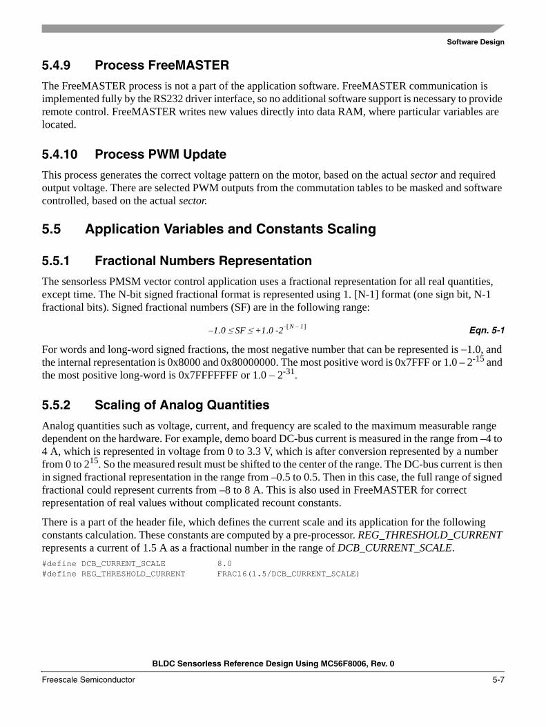
5.5.2 Scaling of Analog Quantities
Analog quantities such as voltage, current, and frequency are scaled to the maximum measurable range dependent on the hardware. For example, demo board DC-bus current is measured in the range from –4 to 4 A, which is represented in voltage from 0 to 3.3 V, which is after conversion represented by a number from 0 to 215. So the measured result must be shifted to the center of the range. The DC-bus current is then in signed fractional representation in the range from –0.5 to 0.5. Then in this case, the full range of signed fractional could represent currents from –8 to 8 A. This is also used in FreeMASTER for correct representation of real values without complicated recount constants.
There is a part of the header file, which defines the current scale and its application for the following constants calculation. These constants are computed by a pre-processor. REG_THRESHOLD_CURRENT represents a current of 1.5 A as a fractional number in the range of DCB_CURRENT_SCALE.#define DCB_CURRENT_SCALE 8.0#define REG_THRESHOLD_CURRENT FRAC16(1.5/DCB_CURRENT_SCALE)
1.0– SF +1.0 -2 N 1–[ ]–≤ ≤
Software Design
BLDC Sensorless Reference Design Using MC56F8006, Rev. 0
5-8 Freescale Semiconductor
The next example of source code is the calculation of 20 % and 80 % of DC-bus voltage. In the first step there are constants defined that represent 20 % and 80 % in fractional.#define V_DCB_LOW FRAC16(0.2)// low limit of BEMF window - 20%#define V_DCB_HI FRAC16(0.8)// high limit of BEMF window - 80%
The defined constants are used for computation using one of the intrinsic functions that multiply two 16-bit fractional values and round them into a 16-bit fractional result.vDcbLowLimit=__mult_r(vDcb,V_DCB_LOW);vDcbHighLimit=__mult_r(vDcb,V_DCB_HI);
Software Design
BLDC Sensorless Reference Design Using MC56F8006, Rev. 0
Freescale Semiconductor 5-9
5.6 Algorithms Realisation
5.6.1 ADC Sampling Mechanism
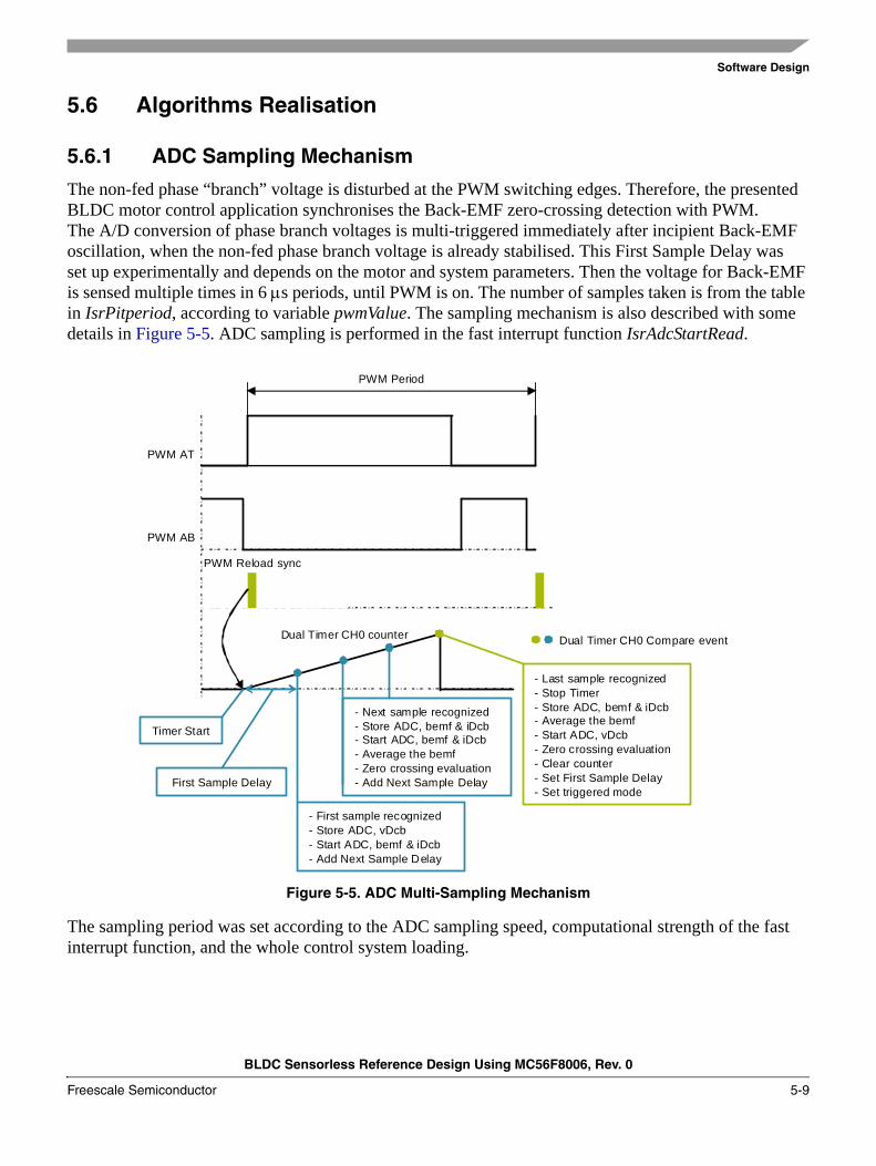
The non-fed phase “branch” voltage is disturbed at the PWM switching edges. Therefore, the presented BLDC motor control application synchronises the Back-EMF zero-crossing detection with PWM. The A/D conversion of phase branch voltages is multi-triggered immediately after incipient Back-EMF oscillation, when the non-fed phase branch voltage is already stabilised. This First Sample Delay was set up experimentally and depends on the motor and system parameters. Then the voltage for Back-EMF is sensed multiple times in 6 μs periods, until PWM is on. The number of samples taken is from the table in IsrPitperiod, according to variable pwmValue. The sampling mechanism is also described with some details in Figure 5-5. ADC sampling is performed in the fast interrupt function IsrAdcStartRead.
Figure 5-5. ADC Multi-Sampling Mechanism
The sampling period was set according to the ADC sampling speed, computational strength of the fast interrupt function, and the whole control system loading.
PWM Reload sync
First Sample Delay
Dual Timer CH0 Compare event
- First sample recognized- Store ADC, vDcb- Start ADC, bemf & iDcb- Add Next Sample Delay
- Next sample recognized- Store ADC, bemf & iDcb- Start ADC, bemf & iDcb- Average the bemf- Zero crossing evaluation- Add Next Sample Delay
- Last sample recognized- Stop Timer- Store ADC, bemf & iDcb- Average the bemf- Start ADC, vDcb- Zero crossing evaluation- Clear counter- Set First Sample Delay- Set triggered mode
PWM AT
PWM AB
PWM Period
Timer Start
Dual Timer CH0 counter
Software Design
BLDC Sensorless Reference Design Using MC56F8006, Rev. 0
5-10 Freescale Semiconductor
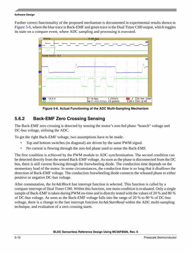
Further correct functionality of the proposed mechanism is documented in experimental results shown in Figure 5-6, where the blue trace is Back-EMF and green trace is the Dual Timer CH0 output, which toggles its state on a compare event, where ADC sampling and processing is executed.
Figure 5-6. Actual Functioning of the ADC Multi-Sampling Mechanism
5.6.2 Back-EMF Zero Crossing Sensing
The Back-EMF zero crossing is detected by sensing the motor’s non-fed phase “branch“ voltage and DC-bus voltage, utilising the ADC.
To get the right Back-EMF voltage, two assumptions have to be made:• Top and bottom switches (in diagonal) are driven by the same PWM signal.• No current is flowing through the non-fed phase used to sense the Back-EMF.
The first condition is achieved by the PWM module to ADC synchronisation. The second condition can be detected directly from the sensed Back-EMF voltage. As soon as the phase is disconnected from the DC bus, there is still current flowing through the freewheeling diode. The conduction time depends on the momentary load of the motor. In some circumstances, the conduction time is so long that it disallows the detection of Back-EMF voltage. The conduction freewheeling diode connects the released phase to either positive or negative DC-bus voltage.
After commutation, the IsrAdcBlock fast interrupt function is selected. This function is called by a compare interrupt of Dual Timer CH0. Within this function, one main condition is evaluated. Only a single sample of Back-EMF is taken during PWM on-time and is directly tested with the values of 20 % and 80 % of DC-bus voltage. As soon as the Back-EMF voltage falls into the range of 20 % to 80 % of DC-bus voltage, there is a change to the fast interrupt function IsrAdcStartRead within the ADC multi-sampling technique, and evaluation of a zero crossing starts.
Software Design
BLDC Sensorless Reference Design Using MC56F8006, Rev. 0
Freescale Semiconductor 5-11
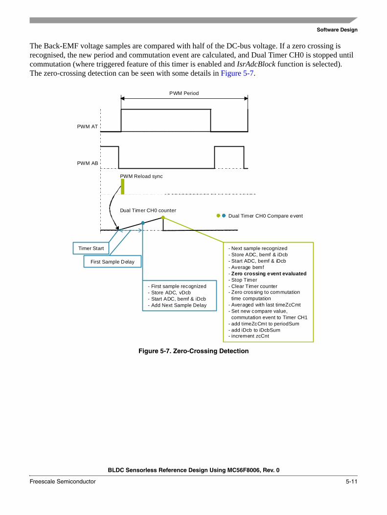
The Back-EMF voltage samples are compared with half of the DC-bus voltage. If a zero crossing is recognised, the new period and commutation event are calculated, and Dual Timer CH0 is stopped until commutation (where triggered feature of this timer is enabled and IsrAdcBlock function is selected). The zero-crossing detection can be seen with some details in Figure 5-7.
Figure 5-7. Zero-Crossing Detection
PWM Reload sync
First Sample Delay
Dual Timer CH0 Compare event
- First sample recognized- Store ADC, vDcb- Start ADC, bemf & iDcb- Add Next Sample Delay
- Next sample recognized- Store ADC, bemf & iDcb- Start ADC, bemf & iDcb- Average bemf- Zero crossing event evaluated- Stop Timer- Clear Timer counter- Zero crossing to commutation
time computation- Averaged with last timeZcCmt- Set new compare value,
commutation event to Timer CH1- add timeZcCmt to periodSum- add iDcb to iDcbSum- increment zcCnt
PWM AT
PWM AB
PWM Period
Dual Timer CH0 counter
Timer Start
Software Design
BLDC Sensorless Reference Design Using MC56F8006, Rev. 0
5-12 Freescale Semiconductor
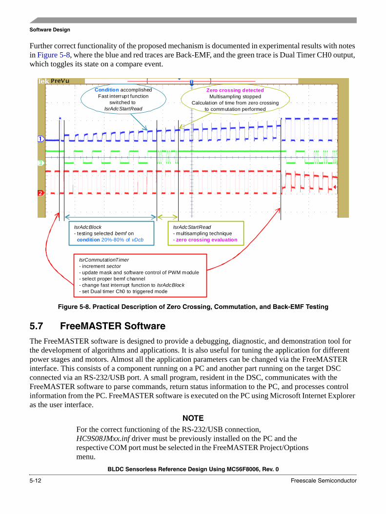
Further correct functionality of the proposed mechanism is documented in experimental results with notes in Figure 5-8, where the blue and red traces are Back-EMF, and the green trace is Dual Timer CH0 output, which toggles its state on a compare event.
Figure 5-8. Practical Description of Zero Crossing, Commutation, and Back-EMF Testing
5.7 FreeMASTER SoftwareThe FreeMASTER software is designed to provide a debugging, diagnostic, and demonstration tool for the development of algorithms and applications. It is also useful for tuning the application for different power stages and motors. Almost all the application parameters can be changed via the FreeMASTER interface. This consists of a component running on a PC and another part running on the target DSC connected via an RS-232/USB port. A small program, resident in the DSC, communicates with the FreeMASTER software to parse commands, return status information to the PC, and processes control information from the PC. FreeMASTER software is executed on the PC using Microsoft Internet Explorer as the user interface.
NOTEFor the correct functioning of the RS-232/USB connection, HC9S08JMxx.inf driver must be previously installed on the PC and the respective COM port must be selected in the FreeMASTER Project/Options menu.
IsrAdcBlock- testing selected bemf on
condition 20%-80% of vDcb
IsrAdcStartRead- multisampling technique- zero crossing evaluation
IsrCommutationTimer- increment sector- update mask and software control of PWM module- select proper bemf channel- change fast interrupt function to IsrAdcBlock- set Dual timer Ch0 to triggered mode
Condition accomplishedFast interrupt function
switched to IsrAdcStartRead
Zero crossing detectedMultisampling stopped
Calculation of time from zero crossingto commutation performed
Software Design
BLDC Sensorless Reference Design Using MC56F8006, Rev. 0
Freescale Semiconductor 5-13
5.7.1 FreeMASTER Serial Communication Driver
This application includes the FreeMASTER Serial Communication Driver. The FreeMASTER Serial Communication Driver fully replaces the former PC Master driver. The new FreeMASTER driver remains fully compatible with the communication interface provided by the old PC Master drivers, bringing many useful enhancements and optimizations.
The primary advantage of the new driver is unification across all supported Freescale processor products and several new features that were added. One of the key features implemented in the new driver is target-side addressing (TSA) that enables an embedded application to describe the memory objects it grants the host access to. By enabling the TSA-Safe option, the application memory can be protected from illegal or invalid memory accesses.
To include the new FreeMASTER serial communication driver in the application, the user has to manually include the driver files in the CodeWarrior project. For this application, the driver has already been included.
The FreeMASTER driver files are located in the following folders:• {Project}support\freemaster\56F8xxx — contains platform-dependent driver C-source and header
files, including a master header file freemaster.h.• {Project}support\freemaster\common — contains common driver source files shared by the driver
for all supported platforms.
All C files included in the FreeMASTER folders are added to the project for compilation and linking. See the support group in the project. The master header file freemaster.h declares the common data types, macros, and prototypes of the FreeMASTER driver API functions. This must be included in the application by using #include directive, wherever calling of any of the FreeMASTER driver API functions is needed.
The FreeMASTER driver does not perform any initialization or configuration of the SCI module it uses to communicate. It is the user’s responsibility to configure the communication module before the FreeMASTER driver is initialized by the FMSTR_Init() call. The default baud rate of the SCI communication is set to 9600 Bd.
FreeMASTER uses a poll-driven communication mode. It does not require the setting of interrupts for the SCI. Both communication and protocol decoding are in the application background loop. The polling-mode requires a periodic call of the FMSTR_Poll() function in the application main.
The driver is configured using the appconfig.h header file. Changes to the file are preferably made through the provided quick start graphical configuration tool in the CodeWarrior toolbar project/configuration tool. The user has to modify this file to configure the FreeMASTER driver. The FreeMASTER driver C-source files include the configuration file and use of the macros defined there for conditional and parameter compilation.
A detailed description of the FreeMASTER serial communication driver is provided in the FreeMASTER Serial Communication Driver User's Manual.
Software Design
BLDC Sensorless Reference Design Using MC56F8006, Rev. 0
5-14 Freescale Semiconductor
5.7.2 FreeMASTER Recorder
Part of the FreeMASTER software is also a recorder able to sample the application variables at a specified sample rate. The samples are stored in a buffer. The sampled data can be displayed in a graph or the data can be stored. The recorder behaves as a simple on-chip oscilloscope with trigger / pre-trigger capabilities. The size of the recorder buffer and the FreeMASTER recorder time base can be defined in the appconfig.h configuration.
The recorder routine must be called periodically from the loop to take samples. The following line must be added to the loop code:
FMSTR_Recorder(); /* FreeMASTER recorder routine call */
In this application, the FreeMASTER recorder is called from the ADC Complete EOS interrupt that creates a 125 μs timebase for the recorder function. A detailed description of the FreeMASTER software is provided in the FreeMASTER Software User Manual.
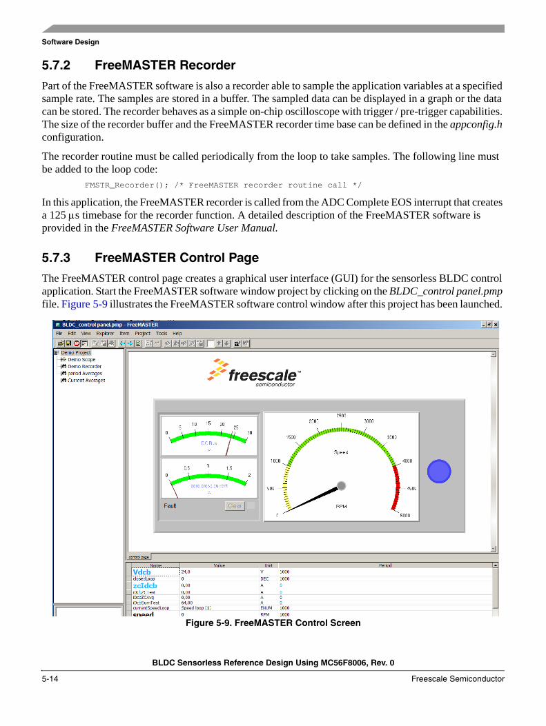
5.7.3 FreeMASTER Control Page
The FreeMASTER control page creates a graphical user interface (GUI) for the sensorless BLDC control application. Start the FreeMASTER software window project by clicking on the BLDC_control panel.pmp file. Figure 5-9 illustrates the FreeMASTER software control window after this project has been launched.
Figure 5-9. FreeMASTER Control Screen
Software Design
BLDC Sensorless Reference Design Using MC56F8006, Rev. 0
Freescale Semiconductor 5-15
The FreeMASTER software control page. These are the main actions that are supported:• Setting the required speed of the motor.• Resetting the application fault status.
The FreeMASTER software control page displays:• DC-Bus current and voltage.• Actual motor speed.• Application status.
For software tuning and demonstration, the following sub-blocks are prepared:• Demonstration measurements.• Control regulators — for adjusting PI controller parameters.
5.8 Software Parameter Settings to a Specific MotorThe default software parameter settings have been tuned to a default hardware setup with the LINIX 45ZWN24-40 motor. The setup is described in Chapter 6, “Application Setup”. If other motors or hardware are used, the software setting needs to be changed according to the specific parameters. Basic parameters and coefficients are described in main.h.

Software Design
BLDC Sensorless Reference Design Using MC56F8006, Rev. 0
5-16 Freescale Semiconductor
BLDC Sensorless Reference Design Using MC56F8006, Rev. 0
Freescale Semiconductor 6-1
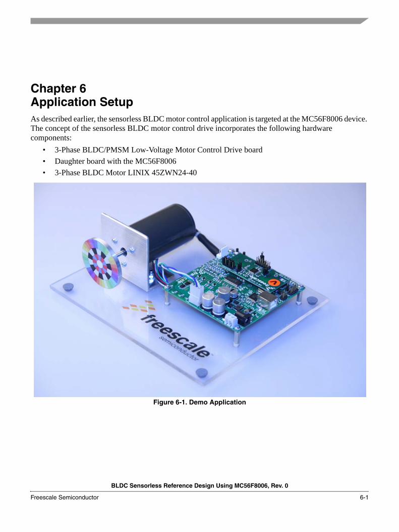
Chapter 6 Application SetupAs described earlier, the sensorless BLDC motor control application is targeted at the MC56F8006 device. The concept of the sensorless BLDC motor control drive incorporates the following hardware components:
• 3-Phase BLDC/PMSM Low-Voltage Motor Control Drive board• Daughter board with the MC56F8006• 3-Phase BLDC Motor LINIX 45ZWN24-40
Figure 6-1. Demo Application
Application Setup
BLDC Sensorless Reference Design Using MC56F8006, Rev. 0
6-2 Freescale Semiconductor
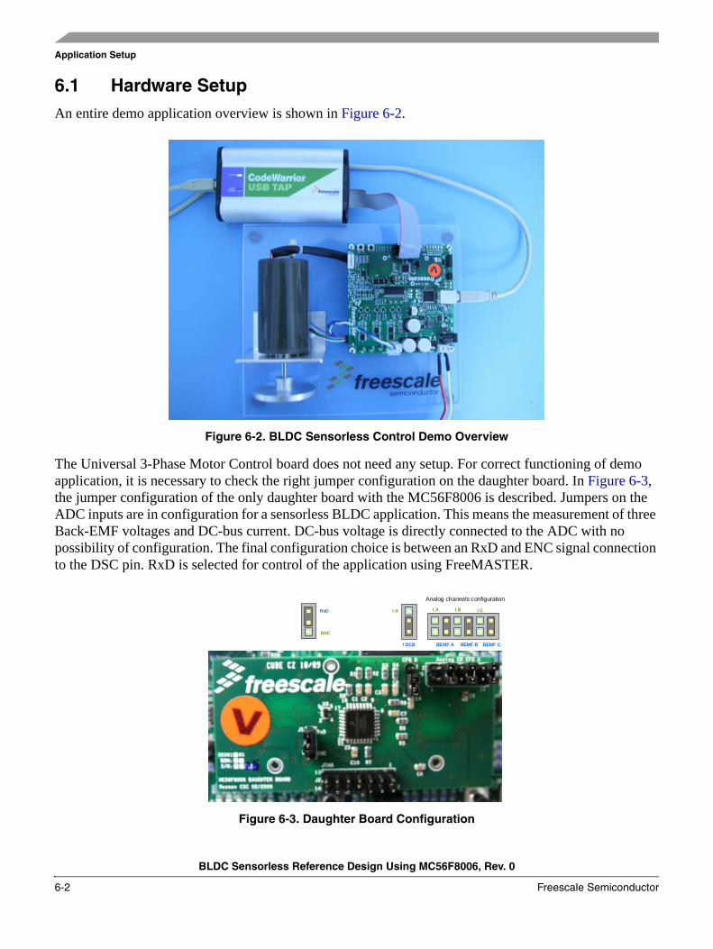
6.1 Hardware SetupAn entire demo application overview is shown in Figure 6-2.
Figure 6-2. BLDC Sensorless Control Demo Overview
The Universal 3-Phase Motor Control board does not need any setup. For correct functioning of demo application, it is necessary to check the right jumper configuration on the daughter board. In Figure 6-3, the jumper configuration of the only daughter board with the MC56F8006 is described. Jumpers on the ADC inputs are in configuration for a sensorless BLDC application. This means the measurement of three Back-EMF voltages and DC-bus current. DC-bus voltage is directly connected to the ADC with no possibility of configuration. The final configuration choice is between an RxD and ENC signal connection to the DSC pin. RxD is selected for control of the application using FreeMASTER.
Figure 6-3. Daughter Board Configuration
Analog channels configuration
I A
BEMF A
I B I C
BEMF B BEMF CI DCB
I ARxD
ENC
Application Setup
BLDC Sensorless Reference Design Using MC56F8006, Rev. 0
Freescale Semiconductor 6-3
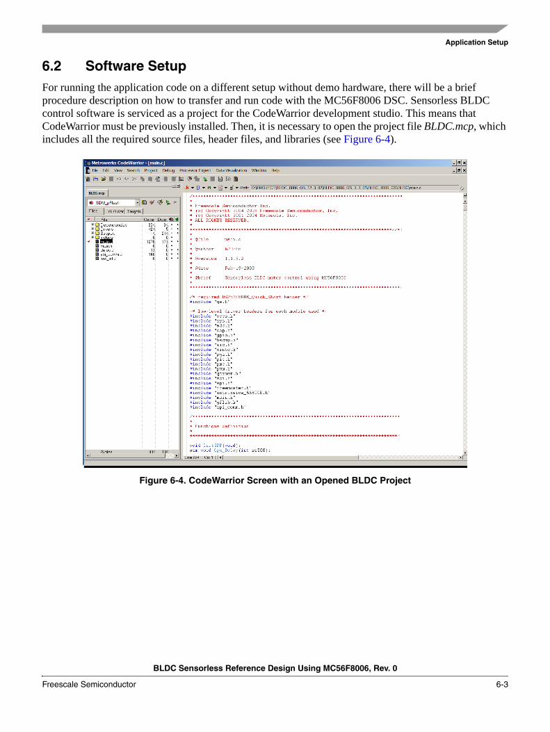
6.2 Software SetupFor running the application code on a different setup without demo hardware, there will be a brief procedure description on how to transfer and run code with the MC56F8006 DSC. Sensorless BLDC control software is serviced as a project for the CodeWarrior development studio. This means that CodeWarrior must be previously installed. Then, it is necessary to open the project file BLDC.mcp, which includes all the required source files, header files, and libraries (see Figure 6-4).
Figure 6-4. CodeWarrior Screen with an Opened BLDC Project
Application Setup
BLDC Sensorless Reference Design Using MC56F8006, Rev. 0
6-4 Freescale Semiconductor
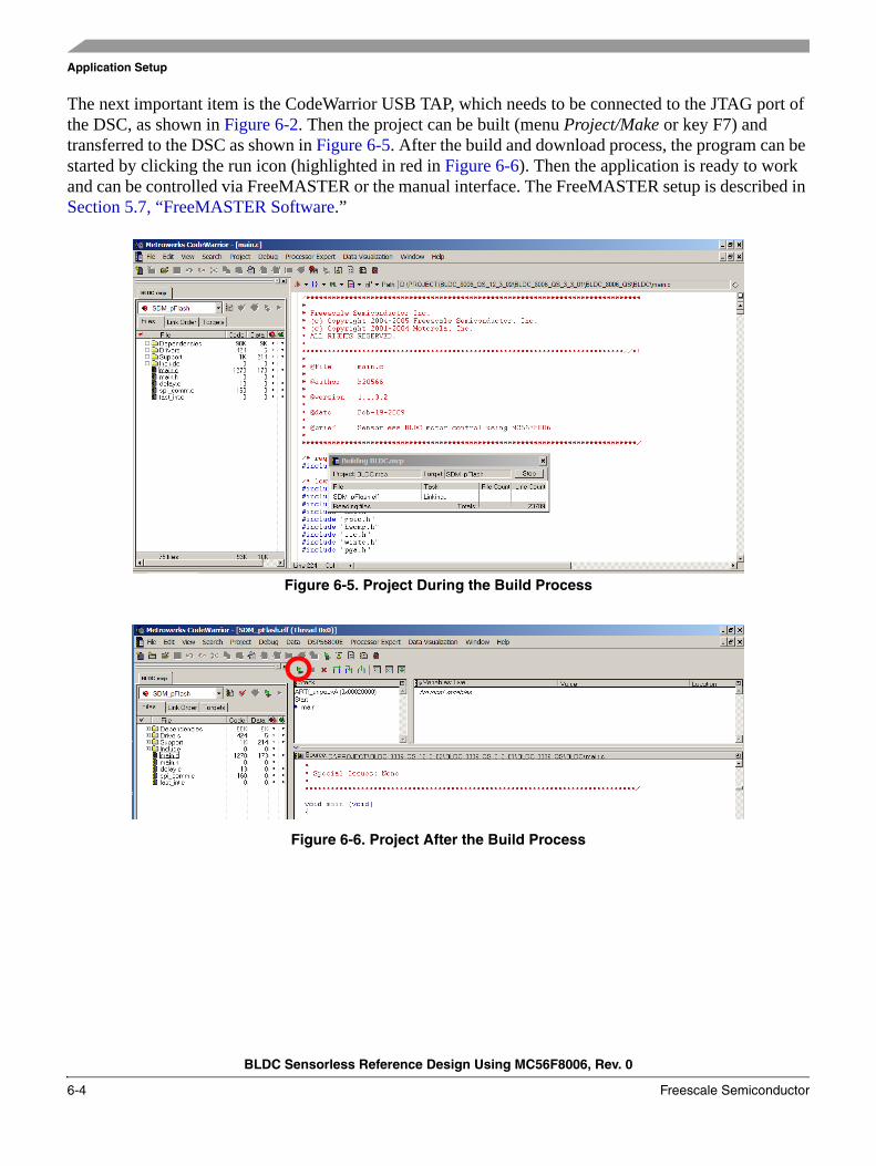
The next important item is the CodeWarrior USB TAP, which needs to be connected to the JTAG port of the DSC, as shown in Figure 6-2. Then the project can be built (menu Project/Make or key F7) and transferred to the DSC as shown in Figure 6-5. After the build and download process, the program can be started by clicking the run icon (highlighted in red in Figure 6-6). Then the application is ready to work and can be controlled via FreeMASTER or the manual interface. The FreeMASTER setup is described in Section 5.7, “FreeMASTER Software.”
Figure 6-5. Project During the Build Process
Figure 6-6. Project After the Build Process
Application Setup
BLDC Sensorless Reference Design Using MC56F8006, Rev. 0
Freescale Semiconductor 6-5
The user can experiment with some tunable application variables, for example the PI controller settings (gainSpeed, integralSpeed, gainCurrent, integralCurrent), current controller thresholds (currentCntrlTh, speedCntrlTh), commutation coefficient (commCoef), and the half DC-bus coefficient (dcbHalfCoef). Default values for these varibles are in main.h file, where constants are defined, and then copied to appropriate variables during initialization. These variables could be tuned on-line using the FreeMASTER tool. For using application with another BLDC motor, design or configuration, the code must be adjusted in accordance to customer requirements. For different motors, the basic modification consists of adapting the commutation tables COMM_TABLE_MASK, COMM_TABLE_SWCTRL, and BEMF_CH_TABLE.
Application Setup
BLDC Sensorless Reference Design Using MC56F8006, Rev. 0
6-6 Freescale Semiconductor
BLDC Sensorless Reference Design Using MC56F8006, Rev. 0
Freescale Semiconductor 7-1
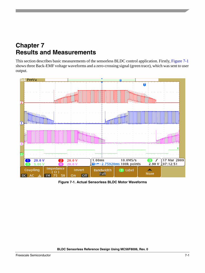
Chapter 7 Results and MeasurementsThis section describes basic measurements of the sensorless BLDC control application. Firstly, Figure 7-1 shows three Back-EMF voltage waveforms and a zero-crossing signal (green trace), which was sent to user output.
Figure 7-1. Actual Sensorless BLDC Motor Waveforms
Results and Measurements
BLDC Sensorless Reference Design Using MC56F8006, Rev. 0
7-2 Freescale Semiconductor
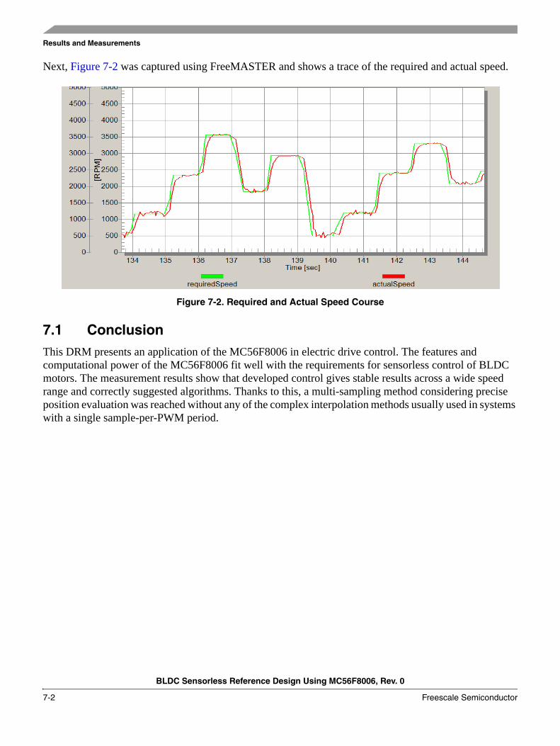
Next, Figure 7-2 was captured using FreeMASTER and shows a trace of the required and actual speed.
Figure 7-2. Required and Actual Speed Course
7.1 ConclusionThis DRM presents an application of the MC56F8006 in electric drive control. The features and computational power of the MC56F8006 fit well with the requirements for sensorless control of BLDC motors. The measurement results show that developed control gives stable results across a wide speed range and correctly suggested algorithms. Thanks to this, a multi-sampling method considering precise position evaluation was reached without any of the complex interpolation methods usually used in systems with a single sample-per-PWM period.