Embed Size (px)
Citation preview

A SIMPLYPERFECT
netWoRk. oPtical netWoRks

2
3
OPti
cAl
SYSt
emS
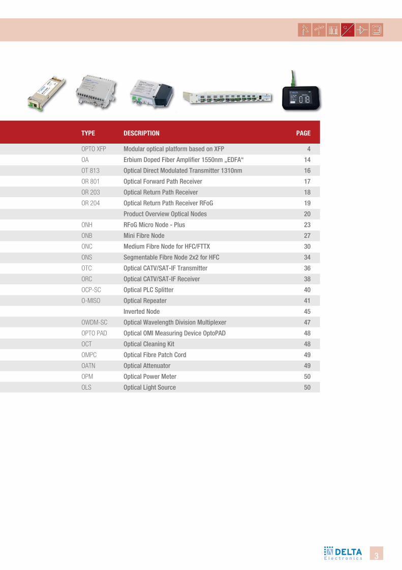
tYPe descRiPtion Page
OPTO XFP modular optical platform based on XFP 4
OA erbium Doped Fiber Amplifier 1550nm „eDFA“ 14
OT 813 Optical Direct modulated transmitter 1310nm 16
OR 801 Optical Forward Path Receiver 17
OR 203 Optical Return Path Receiver 18
OR 204 Optical Return Path Receiver RFog 19
Product Overview Optical nodes 20
ONH RFog micro node - Plus 23
ONB mini Fibre node 27
ONC medium Fibre node for HFc/FttX 30
ONS Segmentable Fibre node 2x2 for HFc 34
OTC Optical cAtV/SAt-iF transmitter 36
ORC Optical cAtV/SAt-iF Receiver 38
OCP-SC Optical Plc Splitter 40
O-MISO Optical Repeater 41
inverted node 45
OWDM-SC Optical wavelength Division multiplexer 47
OPTO PAD Optical Omi measuring Device OptoPAD 48
OCT Optical cleaning Kit 48
OMPC Optical Fibre Patch cord 49
OATN Optical Attenuator 49
OPM Optical Power meter 50
OLS Optical light Source 50
4
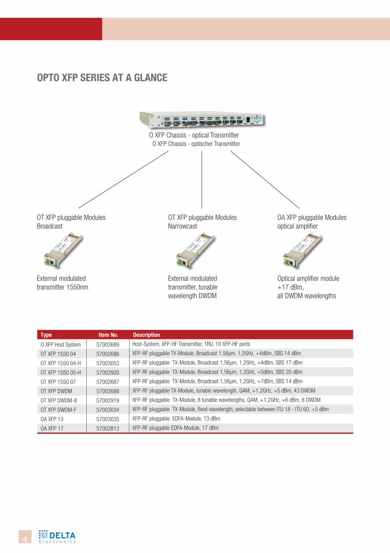
O XFP Chassis - optischer TransmitterO XFP Chassis - optical Transmitter
oPto XfP seRies at a glance
OT XFP pluggable ModulesBroadcast
OT XFP pluggable ModulesNarrowcast
OA XFP pluggable Modulesoptical amplifi er
O XFP Host System
OT XFP 1550 04
OT XFP 1550 04-H
OT XFP 1550 05-H
OT XFP 1550 07
OT XFP DWDM
OT XFP DWDM-8
OT XFP DWDM-F
OA XFP 13
OA XFP 17
type description
57002689
57002686
57003053
57002920
57002687
57002688
57002919
57003034
57003035
57002813
item no.
Host-System, XFP-HF Transmitter, 1RU, 10 XFP-HF ports
XFP-RF pluggable TX-Module, Broadcast 1,56µm, 1,2GHz, +4dBm, SBS 14 dBm
XFP-RF pluggable TX-Module, Broadcast 1,56µm, 1,2GHz, +4dBm, SBS 17 dBm
XFP-RF pluggable TX-Module, Broadcast 1,56µm, 1,2GHz, +5dBm, SBS 20 dBm
XFP-RF pluggable TX-Module, Broadcast 1,56µm, 1,2GHz, +7dBm, SBS 14 dBm
XFP-RF pluggable TX-Module, tunable wavelength, QAM, +1,2GHz, +5 dBm, 43 DWDM
XFP-RF pluggable TX-Module, 8 tunable wavelengths, QAM, +1,2GHz, +6 dBm, 8 DWDM
XFP-RF pluggable TX-Module, fi xed wavelength, selectable between ITU 18 - ITU 60, +5 dBm
XFP-RF pluggable EDFA-Module, 13 dBm
XFP-RF pluggable EDFA-Module, 17 dBm
External modulated transmitter, tunablewavelength DWDM
Optical amplifi er module+17 dBm, all DWDM wavelengths
External modulated transmitter 1550nm
5
OPti
cAl
SYSt
emS
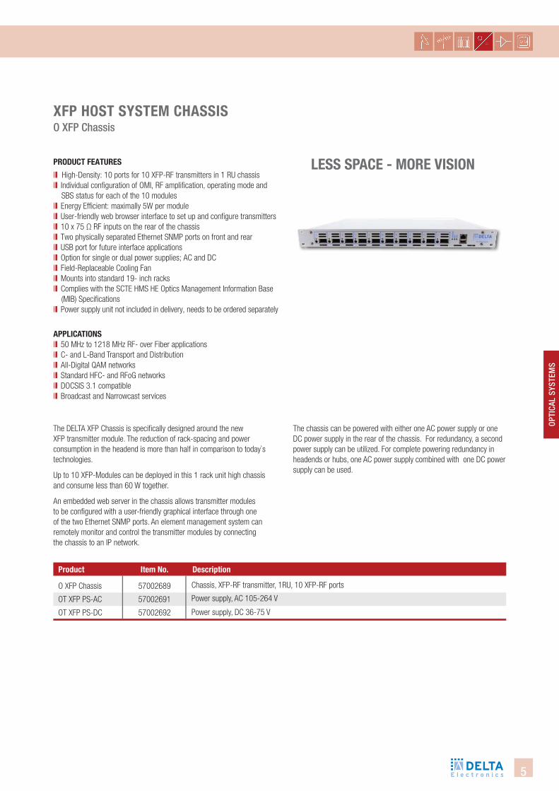
less sPace - MoRe Vision
XfP host sYsteM chassis O XFP chassis
PRodUct featURes
ll High-Density: 10 ports for 10 XFP-RF transmitters in 1 RU chassis ll Individual configuration of OMI, RF amplification, operating mode and SBS status for each of the 10 modulesll Energy Efficient: maximally 5W per module ll User-friendly web browser interface to set up and configure transmitters ll 10 x 75 Ω RF inputs on the rear of the chassis ll Two physically separated Ethernet SNMP ports on front and rear ll USB port for future interface applications ll Option for single or dual power supplies; AC and DCll Field-Replaceable Cooling Fan ll Mounts into standard 19- inch racks ll Complies with the SCTE HMS HE Optics Management Information Base (MIB) Specifications ll Power supply unit not included in delivery, needs to be ordered separately
The DELTA XFP Chassis is specifi cally designed around the new XFP transmitter module. The reduction of rack-spacing and power consumption in the headend is more than half in comparison to today`s technologies.
Up to 10 XFP-Modules can be deployed in this 1 rack unit high chassis and consume less than 60 W together.
An embedded web server in the chassis allows transmitter modules to be confi gured with a user-friendly graphical interface through one of the two Ethernet SNMP ports. An element management system can remotely monitor and control the transmitter modules by connecting the chassis to an IP network.
aPPlicationsll 50 MHz to 1218 MHz RF- over Fiber applicationsll C- and L-Band Transport and Distribution ll All-Digital QAM networks ll Standard HFC- and RFoG networksll DOCSIS 3.1 compatiblell Broadcast and Narrowcast services
O XFP Chassis
OT XFP PS-AC
OT XFP PS-DC
57002689
57002691
57002692
Chassis, XFP-RF transmitter, 1RU, 10 XFP-RF ports
Power supply, AC 105-264 V
Power supply, DC 36-75 V
The chassis can be powered with either one AC power supply or one DC power supply in the rear of the chassis. For redundancy, a second power supply can be utilized. For complete powering redundancy in headends or hubs, one AC power supply combined with one DC power supply can be used.
Product descriptionitem no.
6
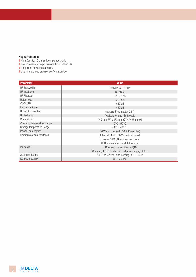
Key Advantages: ll High Density: 10 transmitters per rack-unit ll Power consumption per transmitter less than 5W ll Redundant powering capability ll User-friendly web browser configuration tool
RF Bandwidth RF Input levelRF FlatnessReturn lossCSO/ CTB Link noise figure RF Input connectionRF Test pointDimensionsOperating Temperature RangeStorage Temperature RangePower ConsumptionCommunications interfaces
Indicators
AC Power SupplyDC Power Supply
50 MHz to 1.2 GHz 80 dBµV
+/- 1.5 dB>18 dB>60 dB <20 dB
standard F-connector, 75 Ω Available for each Tx-Module
449 mm (W) x 378 mm (D) x 44.5 mm (H)0°C - 50°C
-40°C - 85°C60 Watts, max. (with 10 XFP modules) Ethernet SNMP, RJ-45 on front panel Ethernet SNMP, RJ-45 on rear panel USB port on front panel (future use) LED for each transmitter port(10)
Summary LED`s for chassis and power supply status 105 – 264 Vrms, auto-sensing; 47 – 63 Hz
36 – 75 Vdc
Parameter Value
7
OPti
cAl
SYSt
emS
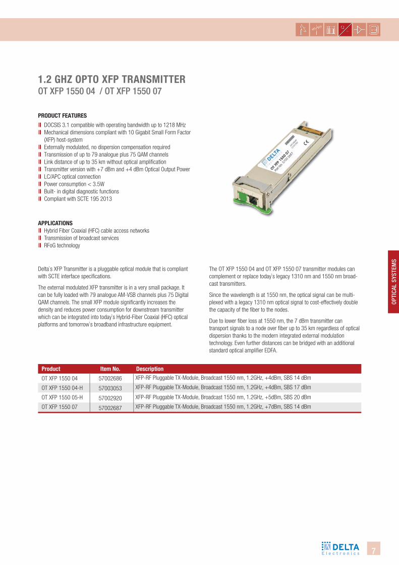
1.2 ghZ oPto XfP tRansMitteR Ot XFP 1550 04 / Ot XFP 1550 07
PRodUct featURes
ll DOCSIS 3.1 compatible with operating bandwidth up to 1218 MHzll Mechanical dimensions compliant with 10 Gigabit Small Form Factor
(XFP) host-systemll Externally modulated, no dispersion compensation requiredll Transmission of up to 79 analogue plus 75 QAM channels ll Link distance of up to 35 km without optical amplification ll Transmitter version with +7 dBm and +4 dBm Optical Output Power ll LC/APC optical connection ll Power consumption < 3.5Wll Built- in digital diagnostic functions ll Compliant with SCTE 195 2013
Delta`s XFP Transmitter is a pluggable optical module that is compliant with SCTE interface specifi cations.
The external modulated XFP transmitter is in a very small package. It can be fully loaded with 79 analogue AM-VSB channels plus 75 Digital QAM channels. The small XFP module signifi cantly increases the density and reduces power consumption for downstream transmitter which can be integrated into today`s Hybrid-Fiber Coaxial (HFC) optical platforms and tomorrow`s broadband infrastructure equipment.
aPPlicationsll Hybrid Fiber Coaxial (HFC) cable access networks ll Transmission of broadcast services ll RFoG technology
OT XFP 1550 04
OT XFP 1550 04-H
OT XFP 1550 05-H
OT XFP 1550 07
Product description
57002686
57003053
57002920
57002687
item no.XFP-RF Pluggable TX-Module, Broadcast 1550 nm, 1.2GHz, +4dBm, SBS 14 dBm
XFP-RF Pluggable TX-Module, Broadcast 1550 nm, 1.2GHz, +4dBm, SBS 17 dBm
XFP-RF Pluggable TX-Module, Broadcast 1550 nm, 1.2GHz, +5dBm, SBS 20 dBm
XFP-RF Pluggable TX-Module, Broadcast 1550 nm, 1.2GHz, +7dBm, SBS 14 dBm
The OT XFP 1550 04 and OT XFP 1550 07 transmitter modules can complement or replace today`s legacy 1310 nm and 1550 nm broad-cast transmitters.
Since the wavelength is at 1550 nm, the optical signal can be multi-plexed with a legacy 1310 nm optical signal to cost-effectively double the capacity of the fi ber to the nodes.
Due to lower fi ber loss at 1550 nm, the 7 dBm transmitter can transport signals to a node over fi ber up to 35 km regardless of optical dispersion thanks to the modern integrated external modulation technology. Even further distances can be bridged with an additional standard optical amplifi er EDFA.
8
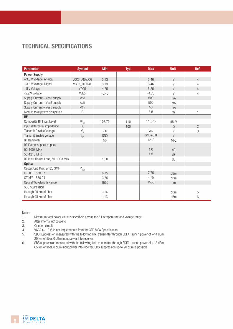
Notes: 1. Maximum total power value is specifield across the full temperature and voltage range2. After internal AC coupling 3. Or open circuit4. VCC2 (+1.8 V) is not implemented from the XFP MSA Specification 5. SBS suppression measured with the following link: transmitter through EDFA, launch power of +14 dBm,
20 km of fiber, 0 dBm input power into receiver6. SBS suppression measured with the following link: transmitter through EDFA, launch power of +13 dBm,
65 km of fiber, 0 dBm input power into receiver. SBS suppression up to 20 dBm is possible
technical sPecifications
Power Supply+3.3 V Voltage, Analog +3.3 V Voltage, Digital +5 V Voltage-5.2 V Voltage Supply Current – Vcc3 supplySupply Current – Vcc5 supplySupply Current – Vee5 supplyModule total power dissipation RFComposite RF Input Level Input differential impedance Transmit Disable VoltageTransmit Enable VoltageRF BandwithRF Flatness, peak to peak 50-1003 MHz50-1218 MHzRF Input Return Loss, 50-1003 MHzOpticalOutput Opt. Pwr: 9/125 SMFOT XFP 1550 07OT XFP 1550 04Optical Wavelength Range SBS Supression through 20 km of fiber through 65 km of fiber
VCC3_ANALOGVCC3_DIGITAL
VCC5VEE5Icc3Icc5Iee5
P
RFin
Rin
VD
VEN
POUT
Parameter symbol Min typ Max Unit Ref.
3.133.134.75-5.46
107,75
2.0GND50
16.0
6.753.751555
+14+13
110100
3.463.465.25-4.75500500503.5
113,75
VccGND+0.8
1218
1.01.5
7.754.751565
VVVV
mAmAmAW
dBµVΩVV
MHz
dBdBdB
dBmdBmnm
dBmdBm
4444
1
23
56
9
OPti
cAl
SYSt
emS
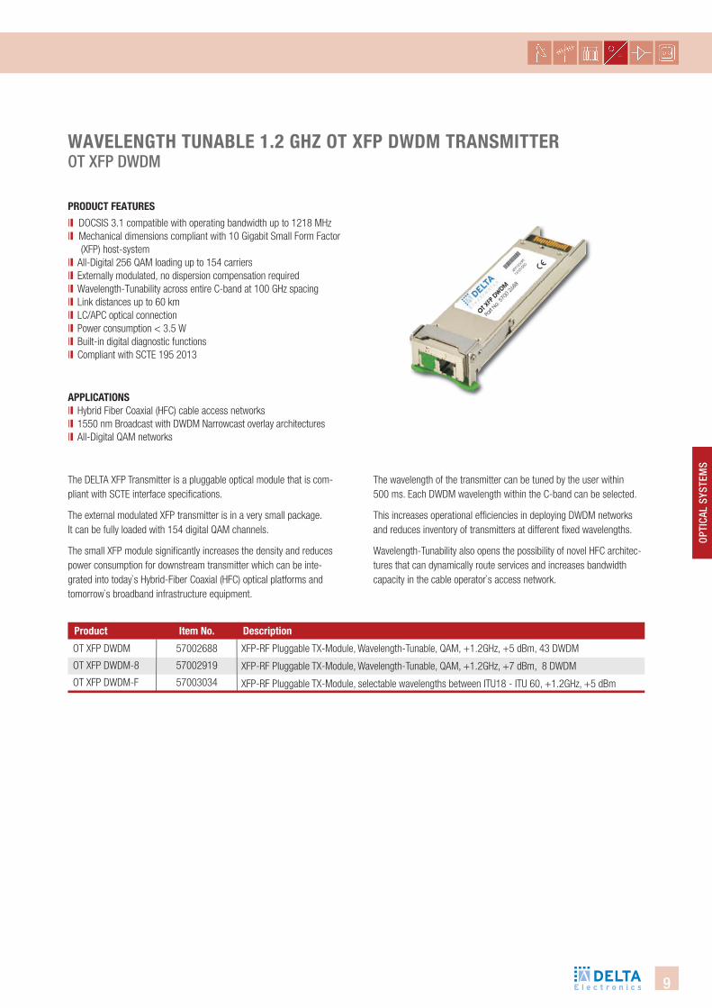
WaVelength tUnable 1.2 ghZ ot XfP dWdM tRansMitteR Ot XFP DwDm
PRodUct featURes
ll DOCSIS 3.1 compatible with operating bandwidth up to 1218 MHzll Mechanical dimensions compliant with 10 Gigabit Small Form Factor (XFP) host-systemll All-Digital 256 QAM loading up to 154 carriersll Externally modulated, no dispersion compensation requiredll Wavelength-Tunability across entire C-band at 100 GHz spacing ll Link distances up to 60 km ll LC/APC optical connection ll Power consumption < 3.5 Wll Built-in digital diagnostic functions ll Compliant with SCTE 195 2013
The DELTA XFP Transmitter is a pluggable optical module that is com-pliant with SCTE interface specifi cations.
The external modulated XFP transmitter is in a very small package. It can be fully loaded with 154 digital QAM channels.
The small XFP module signifi cantly increases the density and reduces power consumption for downstream transmitter which can be inte-grated into today`s Hybrid-Fiber Coaxial (HFC) optical platforms and tomorrow`s broadband infrastructure equipment.
aPPlicationsll Hybrid Fiber Coaxial (HFC) cable access networks ll 1550 nm Broadcast with DWDM Narrowcast overlay architectures ll All-Digital QAM networks
OT XFP DWDM
OT XFP DWDM-8
OT XFP DWDM-F
Product description
57002688
57002919
57003034
item no.
XFP-RF Pluggable TX-Module, Wavelength-Tunable, QAM, +1.2GHz, +5 dBm, 43 DWDM
XFP-RF Pluggable TX-Module, Wavelength-Tunable, QAM, +1.2GHz, +7 dBm, 8 DWDM
XFP-RF Pluggable TX-Module, selectable wavelengths between ITU18 - ITU 60, +1.2GHz, +5 dBm
The wavelength of the transmitter can be tuned by the user within 500 ms. Each DWDM wavelength within the C-band can be selected.
This increases operational effi ciencies in deploying DWDM networks and reduces inventory of transmitters at different fi xed wavelengths.
Wavelength-Tunability also opens the possibility of novel HFC architec-tures that can dynamically route services and increases bandwidth capacity in the cable operator`s access network.
10
Parameter symbol Min typ Max Unit Ref.
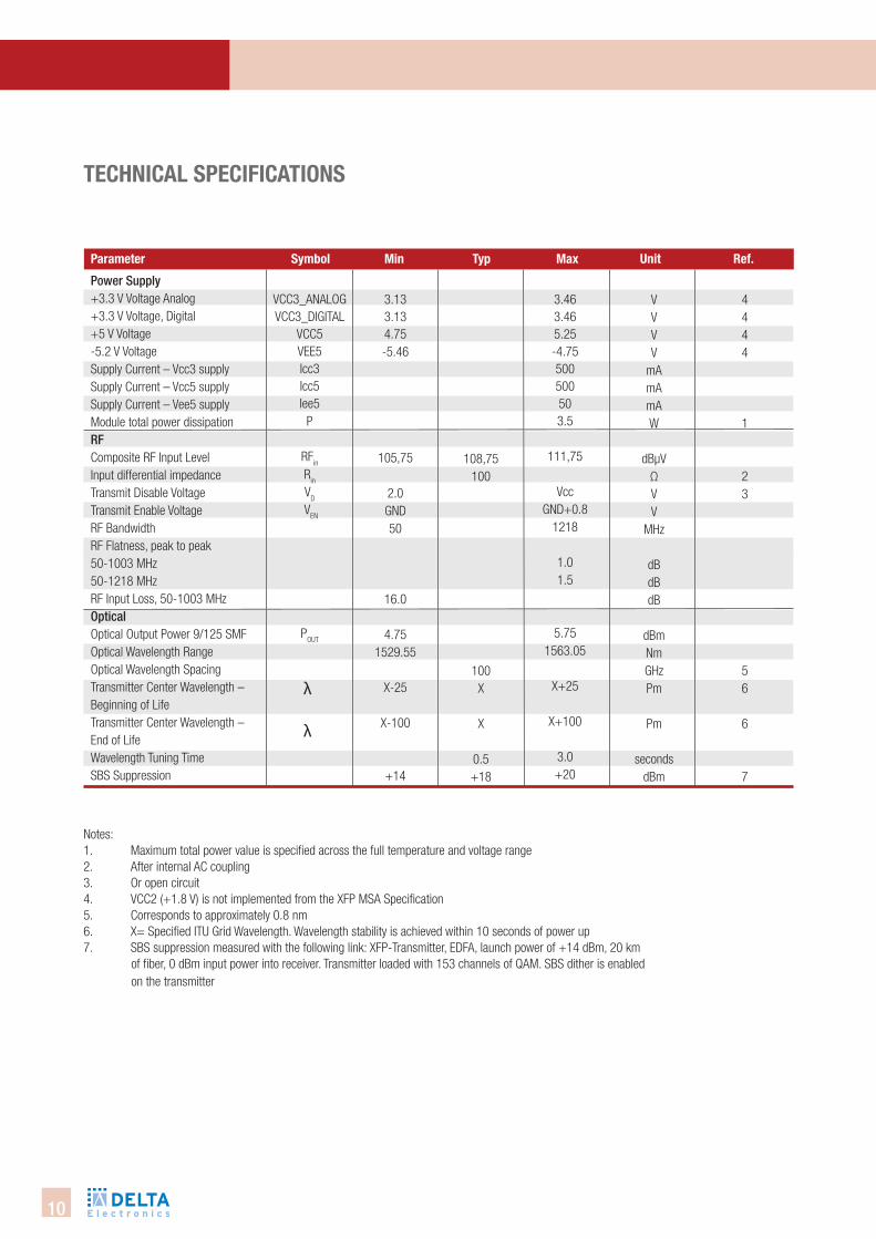
Notes: 1. Maximum total power value is specified across the full temperature and voltage range2. After internal AC coupling 3. Or open circuit 4. VCC2 (+1.8 V) is not implemented from the XFP MSA Specification5. Corresponds to approximately 0.8 nm6. X= Specified ITU Grid Wavelength. Wavelength stability is achieved within 10 seconds of power up 7. SBS suppression measured with the following link: XFP-Transmitter, EDFA, launch power of +14 dBm, 20 km of fiber, 0 dBm input power into receiver. Transmitter loaded with 153 channels of QAM. SBS dither is enabled on the transmitter
technical sPecifications
Power Supply+3.3 V Voltage Analog +3.3 V Voltage, Digital +5 V Voltage-5.2 V Voltage Supply Current – Vcc3 supply Supply Current – Vcc5 supplySupply Current – Vee5 supplyModule total power dissipation RFComposite RF Input Level Input differential impedanceTransmit Disable VoltageTransmit Enable VoltageRF BandwidthRF Flatness, peak to peak 50-1003 MHz50-1218 MHzRF Input Loss, 50-1003 MHzOpticalOptical Output Power 9/125 SMFOptical Wavelength RangeOptical Wavelength Spacing Transmitter Center Wavelength –Beginning of Life Transmitter Center Wavelength –End of Life Wavelength Tuning Time SBS Suppression
VCC3_ANALOGVCC3_DIGITAL
VCC5VEE5Icc3Icc5Iee5
P
RFin
Rin
VD
VEN
POUT
λ λ
3.133.134.75-5.46
105,75
2.0GND50
16.0
4.751529.55
X-25
X-100
+14
108,75100
100X
X
0.5+18
3.463.465.25-4.75500500503.5
111,75
VccGND+0.8
1218
1.01.5
5.751563.05
X+25
X+100
3.0+20
VVVV
mAmAmAW
dBµVΩVV
MHz
dBdBdB
dBmNmGHzPm
Pm
secondsdBm
4444
1
23
56
6
7
11
OPti
cAl
SYSt
emS
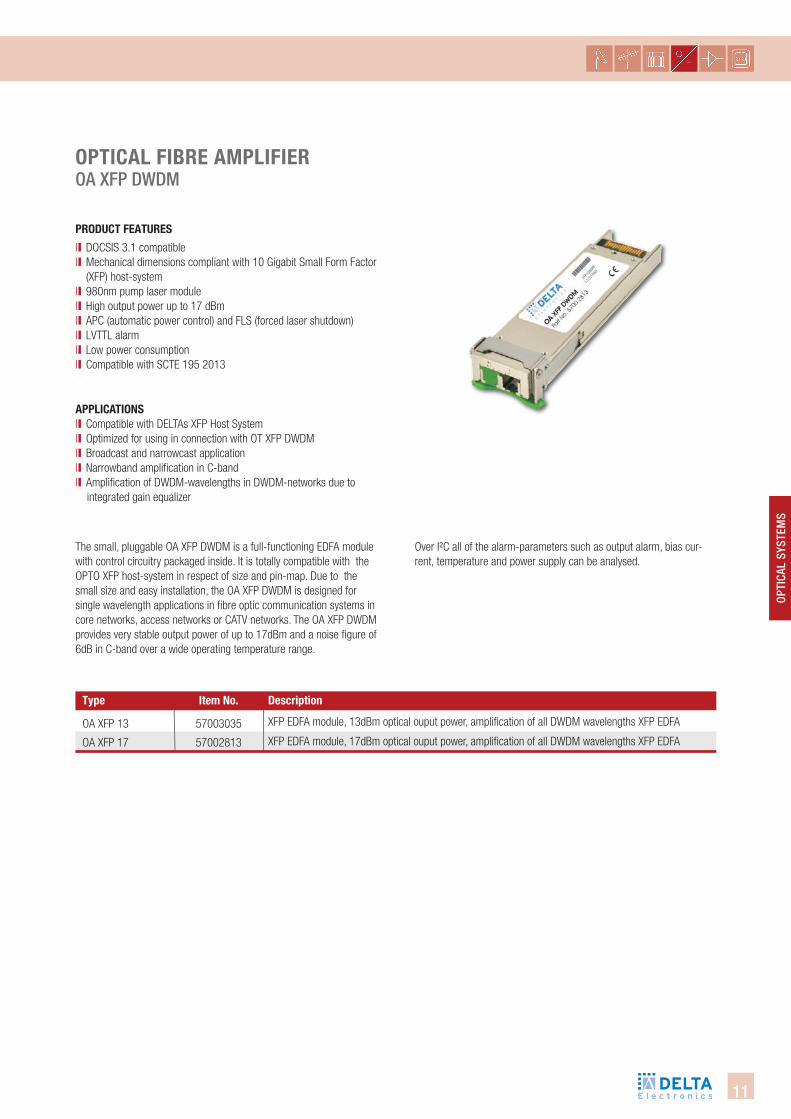
oPtical fibRe aMPlifieR OA XFP DwDm
PRodUct featURes
ll DOCSIS 3.1 compatiblell Mechanical dimensions compliant with 10 Gigabit Small Form Factor
(XFP) host-systemll 980nm pump laser modulell High output power up to 17 dBm ll APC (automatic power control) and FLS (forced laser shutdown)ll LVTTL alarmll Low power consumptionll Compatible with SCTE 195 2013
The small, pluggable OA XFP DWDM is a full-functioning EDFA module with control circuitry packaged inside. It is totally compatible with the OPTO XFP host-system in respect of size and pin-map. Due to the small size and easy installation, the OA XFP DWDM is designed for single wavelength applications in fi bre optic communication systems in core networks, access networks or CATV networks. The OA XFP DWDM provides very stable output power of up to 17dBm and a noise fi gure of 6dB in C-band over a wide operating temperature range.
aPPlicationsll Compatible with DELTAs XFP Host Systemll Optimized for using in connection with OT XFP DWDMll Broadcast and narrowcast applicationll Narrowband amplifi cation in C-bandll Amplifi cation of DWDM-wavelengths in DWDM-networks due to integrated gain equalizer
XFP EDFA module, 13dBm optical ouput power, amplifi cation of all DWDM wavelengths XFP EDFA
XFP EDFA module, 17dBm optical ouput power, amplifi cation of all DWDM wavelengths XFP EDFA
Over I²C all of the alarm-parameters such as output alarm, bias cur-rent, temperature and power supply can be analysed.
type descriptionitem no.
OA XFP 13
OA XFP 17
57003035
57002813
12
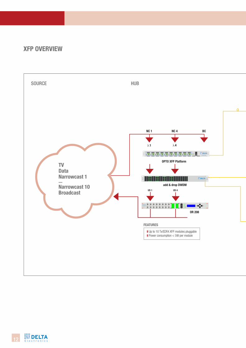
XfP oVeRVieW
SOuRce Hub

13
OPti
cAl
SYSt
emS
uSeR
Ouput Level 114 dBµV
KOAX
Fttb network
FttH network
RF output level 110 dbµV
Low power consumptionNew patented burst technology
Various output level 80-96-99 dbµV
Selectable output by jumperLow power consumption
Distribution network
14
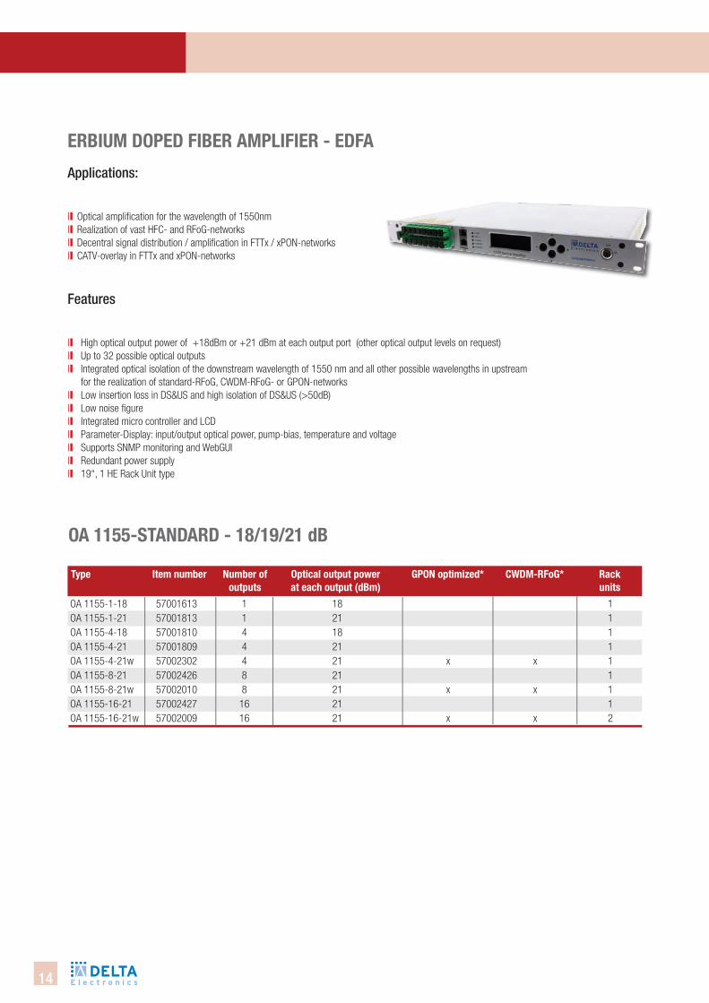
eRbiUM doPed fibeR aMPlifieR - edfa
Applications:
ll Optical amplifi cation for the wavelength of 1550nm ll Realization of vast HFC- and RFoG-networksll Decentral signal distribution / amplifi cation in FTTx / xPON-networksll CATV-overlay in FTTx and xPON-networks
Features
ll High optical output power of +18dBm or +21 dBm at each output port (other optical output levels on request)ll Up to 32 possible optical outputsll Integrated optical isolation of the downstream wavelength of 1550 nm and all other possible wavelengths in upstream
for the realization of standard-RFoG, CWDM-RFoG- or GPON-networks ll Low insertion loss in DS&US and high isolation of DS&US (>50dB)ll Low noise fi gurell Integrated micro controller and LCDll Parameter-Display: input/output optical power, pump-bias, temperature and voltagell Supports SNMP monitoring and WebGUIll Redundant power supplyll 19“, 1 HE Rack Unit type
OA 1155-1-18 57001613OA 1155-1-21 57001813OA 1155-4-18 57001810OA 1155-4-21 57001809OA 1155-4-21w 57002302OA 1155-8-21 57002426OA 1155-8-21w 57002010OA 1155-16-21 57002427OA 1155-16-21w 57002009
1 18 1 1 21 1 4 18 1 4 21 1 4 21 x x 1 8 21 1 8 21 x x 1 16 21 1 16 21 x x 2
oa 1155-standaRd - 18/19/21 db
type item number number of optical output power gPon optimized* cWdM-Rfog* Rack outputs at each output (dbm) units
15
OPti
cAl
SYSt
emS
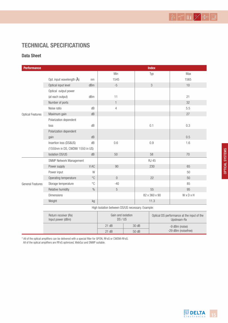
technical sPecifications
Performance index
Min Typ Max
Opt. input wavelength (λ) nm 1545 1565
Optical input level dBm -5 3 10
Optical output power
(at each output) dBm 11 21
Number of ports 1 32
Noise ratio dB 4 5.5
Maximum gain dB 27
Polarization dependent
loss dB 0.1 0.3
Polarization dependent
gain dB 0.5
Insertion loss (DS&US) dB 0.6 0.9 1.6
(1550nm in DS, CWDM/ 1550 in US)
Isolation DS/US dB 50 58 70
Optical Features
General Features
SNMP Network Management RJ 45
Power supply V AC 90 230 65
Power input W 50
Operating temperature °C 0 22 50
Storage temperature °C -40 85
Relative humidity % 5 55 95
Dimensions 82 x 360 x 90 W x D x H
Weight kg 11.3
High Isolation between DS/US necessary. Example:
Return receiver (Rx)Input power (dBm)
Optical DS performance at the input of the Upstream-Rx
21 dB 30 dB
21 dB 50 dB
-9 dBm (noise)-29 dBm (noisefree)
* All of the optical amplifi ers can be delivered with a special fi lter for GPON, RFoG or CWDM-RFoG. All of the optical amplifi ers are RFoG optimized, WebGui and SNMP suitable.
Data Sheet
Gain and isolation DS / US
16
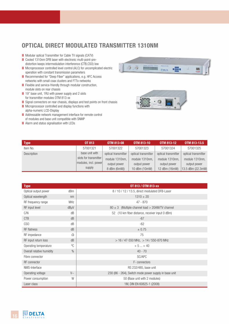
type ot 813 / otM 813-xx
type otM 813-10 otM 813-12 otM 813-13.5otM 813-08ot 813
oPtical diRect ModUlated tRansMitteR 1310nMll Modular optical Transmitter for Cable TV signals (CATV)ll Cooled 1310nm DFB laser with electronic multi-point-pre-
distortion keeps intermodulation interference (CTB,CSO) lowll Microprocessor controlled level control (ALC) for uncomplicated electric
operation with constant transmission parametersll Recommended for “Deep Fiber” applications, e.g. HFC Access
networks with small coax clusters and FTTx-networksll Flexible and service-friendly through modular construction,
module slots on rear chassisll 19” base unit, 1RU with power supply and 2 slots
for transmitter modules OTM 813-xxll Signal connectors on rear chassis, displays and test points on front chassisll Microprocessor controlled and display functions with
alpha-numeric LCD-Displayll Addressable network management interface for remote control
of modules and base unit compatible with SNMPll Alarm and status signalisation with LEDs
Optical output power dBm
Optical wavelength nm
RF frequency range MHz
RF input level dBµV
C/N dB
CTB dB
CSO dB
RF flatness dB
RF impedance Ω
RF input return loss dB
Operating temperature ºC
Overall relative humidity %
Fibre connector
RF connector
NMS-Interface
Operating voltage V~
Power consumption W
Laser class
8 / 10 / 12 / 13.5, direct modulated DFB-Laser
1310 ± 20
47 - 870
80 ± 3 (Multiple channel load > 20AM/TV channel
52 (10 km fiber distance, receiver input 0 dBm)
-67
-62
± 0.75
75
> 16 / 47-550 MHz, > 14 / 550-870 MHz
+ 5 ... + 40
40 - 70
SC/APC
F- connectors
RS 232/485, base unit
230 (86 - 264), Switch mode power supply in base unit
50 (Base unit with 2 modules)
1M, DIN EN 60825-1 (2008)
57001323
optical transmitter
module 1310nm, output power
10 dBm (10mW)
57001325
optical transmitter
module 1310nm, output power
13.5 dBm (22.3mW)
57001324
optical transmitter
module 1310nm, output power
12 dBm (16mW)
Item No.
Description
57001322
optical transmitter
module 1310nm, output power
8 dBm (6mW))
57001321base unit with
slots for transmitter modules, incl. power
supply
17
OPti
cAl
SYSt
emS
type oR 801
type oR 801
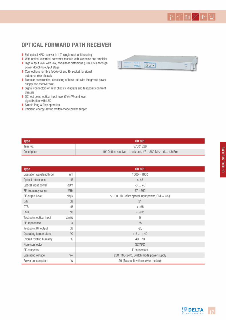
oPtical foRWaRd Path ReceiVeR
Operation wavelength (λ) nm
Optical return loss dB
Optical input power dBm
RF frequency range MHz
RF output Level dBµV
C/N dB
CTB dB
CSO dB
Test point optical input V/mW
RF impedance Ω
Test point RF output dB
Operating temperature °C
Overall relative humidity %
Fibre connector
RF connector
Operating voltage V~
Power consumption W
1000 - 1600
> 45
-6 ... +3
47 - 862
> 100 (@ 0dBm optical input power, OMI = 4%)
51
< -65
< -62
5
75
-20
+ 5 ... + 40
40 - 70
SC/APC
F-connectors
230 (180-244), Switch mode power supply
20 (Base unit with receiver module)
ll Full optical HFC receiver in 19” single rack unit housing ll With optical-electrical converter module with low noise pre-amplifierll High output level with low, non-linear distortions (CTB, CSO) through
power doubling output stagell Connections for fibre (SC/APC) and RF socket for signal
output on rear chassisll Modular construction, consisting of base unit with integrated power
supply and receiver slotll Signal connectors on rear chassis, displays and test points on front
chassisll DC test point, optical input level (5V/mW) and level
signalization with LEDll Simple Plug & Play operationll Efficient, energy-saving switch-mode power supply
Item No.
Description
57001328
19” Optical receiver, 1 rack unit, 47 – 862 MHz, -6…+3dBm
18
type oR 203 + oRM 200
type oR 203 oRM 200
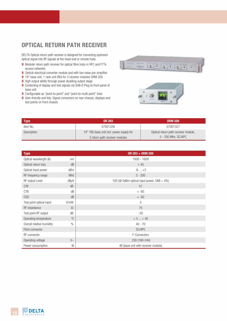
DELTA Optical return path receiver is designed for converting upstream optical signal into RF signals at the head-end or remote hubs
ll Modular return path receiver for optical fibre hubs in HFC and FTTx access networks
ll Optical-electrical converter module and with low noise pre-amplifierll 19” base unit, 1 rack unit (RU) for 3 receiver modules ORM 200ll High output ability through power doubling output stage ll Contacting of display and test signals via SUB-D Plug to front panel of
base unitll Configurable as “point-to-point” and “point-to-multi-point” linksll User-friendly and tidy: Signal connectors on rear chassis, displays and
test points on front chassis
Optical wavelength (λ) nm
Optical return loss dB
Optical input power dBm
RF frequency range MHz
RF output Level dBµV
C/N dB
CTB dB
CSO dB
Test point optical input V/mW
RF impedance Ω
Test point RF output dB
Operating temperature ºC
Overall relative humidity %
Fibre connector
RF connector
Operating voltage V~
Power consumption W
1000 - 1600
> 45
-6 ... +3
5 - 200
100 (@ 0dBm optical input power, OMI = 4%)
51
< -65
< -62
5
75
-20
+ 5 ... + 40
40 - 70
SC/APC
F-Connectors
230 (180-244)
46 (base unit with receiver module)
oPtical RetURn Path ReceiVeR
Item No.
Description
57001326
19” 1RU base unit incl. power supply for
3 return path receiver modules
57001327
Optical return path receiver module, 5 - 200 MHz, SC/APC
19
OPti
cAl
SYSt
emS
type oR 204 l oR 208 l oR 204 h oR 208 h
type
57001601
return path receiver
1260..1620nm, 4 inputs,
4 RF-outputs,
SC/APC,
80 MHz return path
57002922
return path receiver
1260..1620nm, 8 inputs,
8 RF-outputs,
SC/APC,
80 MHz return path
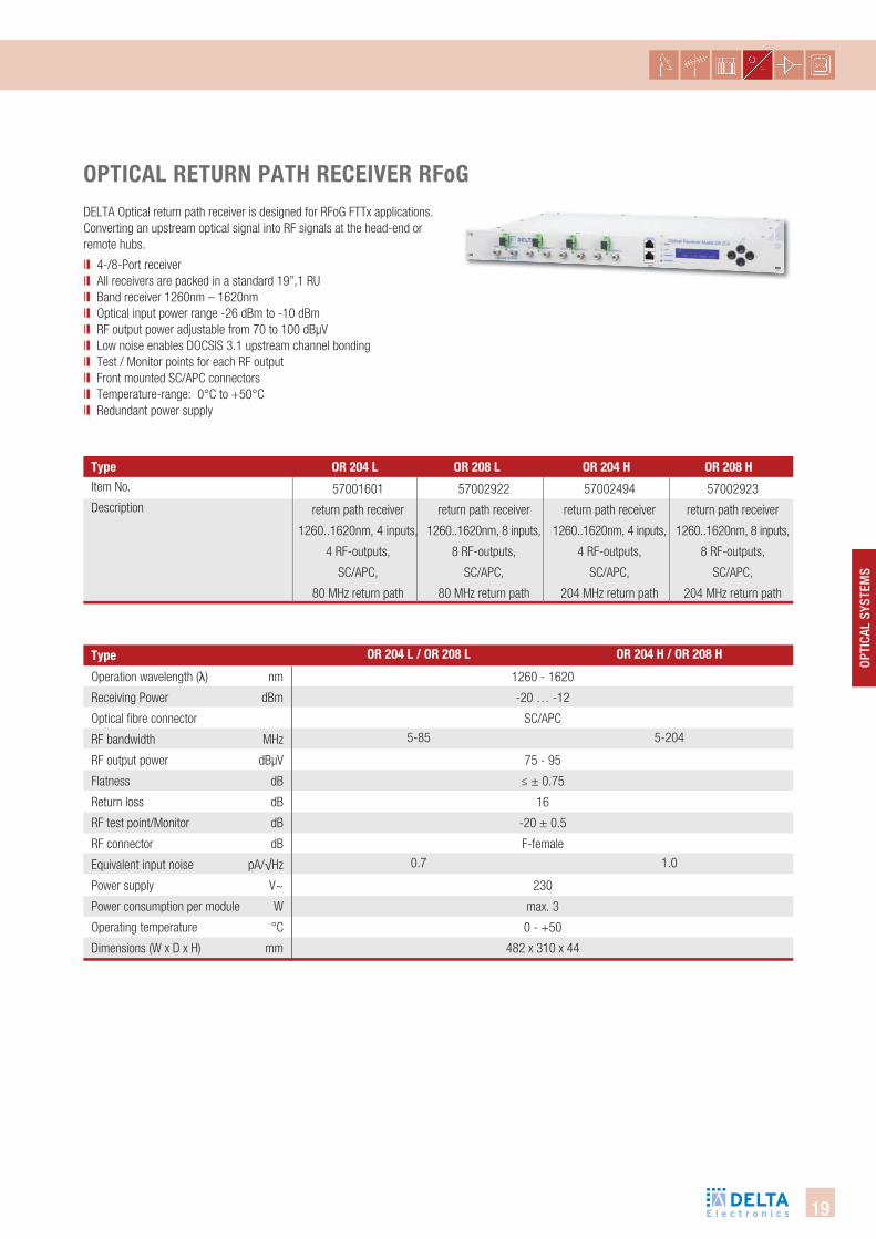
oPtical RetURn Path ReceiVeR RfogDELTA Optical return path receiver is designed for RFoG FTTx applications. Converting an upstream optical signal into RF signals at the head-end or remote hubs.
ll 4-/8-Port receiver ll All receivers are packed in a standard 19”,1 RUll Band receiver 1260nm – 1620nmll Optical input power range -26 dBm to -10 dBmll RF output power adjustable from 70 to 100 dBµVll Low noise enables DOCSIS 3.1 upstream channel bondingll Test / Monitor points for each RF outputll Front mounted SC/APC connectorsll Temperature-range: 0°C to +50°Cll Redundant power supply
Item No.
Description57002494
return path receiver
1260..1620nm, 4 inputs,
4 RF-outputs,
SC/APC,
204 MHz return path
57002923
return path receiver
1260..1620nm, 8 inputs,
8 RF-outputs,
SC/APC,
204 MHz return path
Operation wavelength (λ) nm
Receiving Power dBm
Optical fibre connector
RF bandwidth MHz
RF output power dBµV
Flatness dB
Return loss dB
RF test point/Monitor dB
RF connector dB
Equivalent input noise pA/√Hz
Power supply V~
Power consumption per module W
Operating temperature °C
Dimensions (W x D x H) mm
1260 - 1620
-20 … -12
SC/APC
75 - 95
≤ ± 0.75
16
-20 ± 0.5
F-female
230
max. 3
0 - +50
482 x 310 x 44
oR 204 l / oR 208 l
5-85
0.7
oR 204 h / oR 208 h
5-204
1.0
20
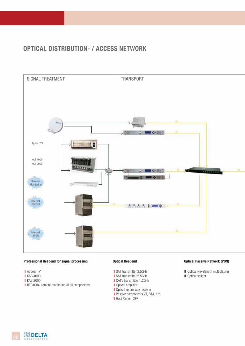
Professional headend for signal processing
ll Appear TVll KAB 4000ll KAB 2000ll HEC1004, remote monitoring of all components
SignAl tReAtment tRAnSPORt
optical headend
ll SAT transmitter 2.5GHzll SAT transmitter 5.5GHzll CATV transmitter 1.2GHzll Optical amplifierll Optical return way receiverll Passive components VT, STA, etcll Host System XFP
optical Passive network (Pon)
ll Optical wavelength multiplexingll Optical splitter
Appear tV
KAb 4000KAb 2000
internet DOcSiS
Remote monitoring
internet XPOn
oPtical distRibUtion- / access netWoRk
21
Opti
cal
SySt
emS
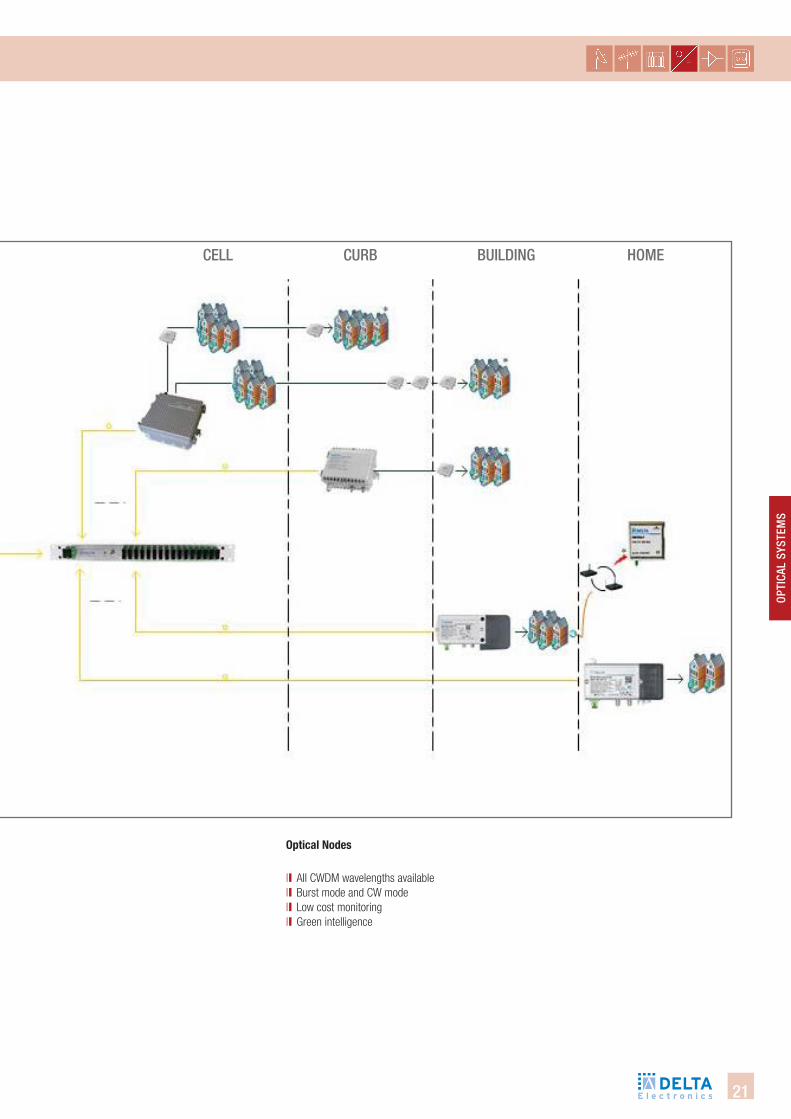
cell cuRb builDing HOme
optical nodes
ll AII CWDM wavelengths available ll Burst mode and CW modell Low cost monitoringll Green intelligence
22
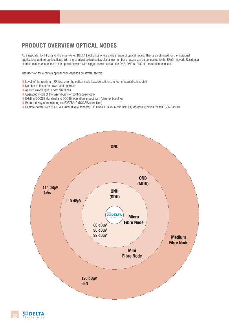
onh (sdU)
onb(MdU)
onc
Micro fibre node
Mini fibre node
Mediumfibre node
80 dbµV96 dbµV99 dbµV
110 dbµV
114 dbµVgaAs
120 dbµVgan
PRodUct oVeRVieW oPtical nodesAs a specialist for HFC- and RFoG-networks, DELTA Electronics offers a wide range of optical nodes. They are optimized for the individual applications at different locations. With the smallest optical nodes also a low number of users can be connected to the RFoG-network. Residential districts can be connected to the optical network with bigger nodes such as the ONB, ONC or ONS in a redundant concept.
The decision for a certain optical node depends on several factors:
ll Level of the maximum RF-loss after the optical node (passive splitters, length of coaxial cable, etc.)ll Number of fibers for down- and upstreamll Applied wavelength in both directionsll Operating mode of the laser (burst- or continuous-mode)ll Existing DOCSIS standard and DOCSIS operation in upstream (channel bonding)ll Preferred way of monitoring via FOSTRA-D (DOCSIS compliant)ll Remote-control with FOSTRA-F (new RFoG Standard): DS ON/OFF, Burst Mode ON/OFF, Ingress Detection Switch 0 / 6 / 45 dB

23
Opti
cal
SySt
emS
PRodUct oVeRVieW oPtical nodes accessoRies
type item no. descriptionFOSTRA-FRLK 565-1RLK 585-1RLK 5200VM 302AM 301-10 AAM 301-10 BLPF 5-65LPF 5-85HPF 85-1HPF 105-1PAD 0PAD 1PAD 2PAD 3 PAD 4PAD 5PAD 6PAD 7PAD 8PAD 9PAD 10PAD 11PAD 12PAD 13PAD 14PAD 15PAD 16PAD 17PAD 18PAD 19PAD 20
5700198157002732570027335700277657002092570020935700211757002295570022965700229757002298101615231016152410161525101615261016152710161528101615291016153010161531101615321016153310161534101615351016153610161537101615381016153910161540101615411016154210161543
FSK Receiver, Rx: 868 MHzDiplexer, 5-65 / 85 - 1218 MHzDiplexer, 5-85 / 105 - 1218 MHzDiplexer, 5-204 / 258 - 1218 MHzSplitter, two-way, 4.5 dBTap 10 dB, Tap outTap 10 dB, Line outLow pass filter 5-65 MHzLow pass filter 5-85 MHzHigh pass filter 85-1218 MHzHigh pass filter 105-1218 MHzAttenuation PAD 0 dBAttenuation PAD 1 dBAttenuation PAD 2 dBAttenuation PAD 3 dBAttenuation PAD 4 dBAttenuation PAD 5 dBAttenuation PAD 6 dBAttenuation PAD 7 dBAttenuation PAD 8 dBAttenuation PAD 9 dBAttenuation PAD 10 dBAttenuation PAD 11 dBAttenuation PAD 12 dBAttenuation PAD 13 dBAttenuation PAD 14 dBAttenuation PAD 15 dBAttenuation PAD 16 dBAttenuation PAD 17 dBAttenuation PAD 18 dBAttenuation PAD 19 dBAttenuation PAD 20 dB
24
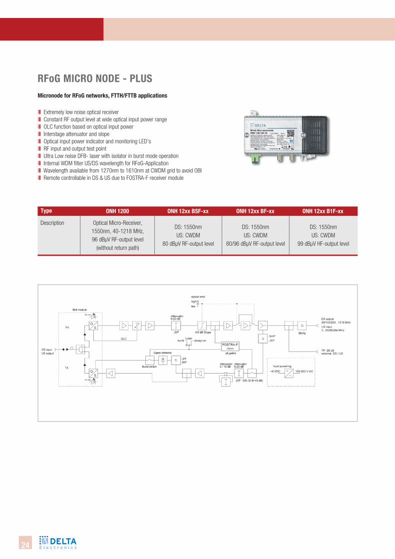
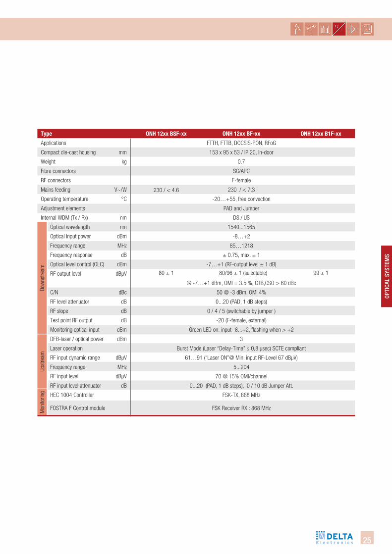
Rfog MicRo node - PlUsMicronode for Rfog networks, ftth/fttb applications
ll Extremely low noise optical receiverll Constant RF output level at wide optical input power range ll OLC function based on optical input powerll Interstage attenuator and slope ll Optical input power indicator and monitoring LED’sll RF input and output test pointll Ultra Low noise DFB- laser with isolator in burst mode operation ll Internal WDM filter US/DS wavelength for RFoG-Applicationll Wavelength available from 1270nm to 1610nm at CWDM grid to avoid OBI ll Remote controllable in DS & US due to FOSTRA-F receiver module
Description
type onh 1200 onh 12xx bf-xx onh 12xx b1f-xx
Optical Micro-Receiver, 1550nm, 40-1218 MHz, 96 dBµV RF-output level
(without return path)
DS: 1550nmUS: CWDM
80/96 dBµV RF-output level
DS: 1550nmUS: CWDM
99 dBµV HF-output level
DS: 1550nmUS: CWDM
80 dBµV RF-output level
onh 12xx bsf-xx
25
Opti
cal
SySt
emS
Upst
ream
Dow
nstre
amM
onito
ring
type
Applications
Compact die-cast housing mm
Weight kg
Fibre connectors
RF connectors
Mains feeding V~/W
Operating temperature °C
Adjustment elements
Internal WDM (Tx / Rx) nm
Optical wavelength nm
Optical input power dBm
Frequency range MHz
Frequency response dB
Optical level control (OLC) dBm
RF output level dBµV
C/N dBc
RF level attenuator dB
RF slope dB
Test point RF output dB
Monitoring optical input dBm
DFB-laser / optical power dBm
Laser operation
RF input dynamic range dBµV
Frequency range MHz
RF input level dBµV
RF input level attenuator dB
HEC 1004 Controller
FOSTRA F Control module
onh 12xx bsf-xx onh 12xx b1f-xx
FTTH, FTTB, DOCSIS-PON, RFoG
153 x 95 x 53 / IP 20, In-door
0.7
SC/APC
F-female
230 / < 7.3
-20…+55, free convection
PAD and Jumper
DS / US
1540...1565
-8…+2
85…1218
± 0.75, max. ± 1
-7…+1 (RF-output level ± 1 dB)
@ -7…+1 dBm, OMI = 3.5 %, CTB,CSO > 60 dBc
50 @ -3 dBm, OMI 4%
0...20 (PAD, 1 dB steps)
0 / 4 / 5 (switchable by jumper )
-20 (F-female, external)
Green LED on: input -8...+2, flashing when > +2
3
Burst Mode (Laser “Delay-Time” ≤ 0,8 µsec) SCTE compliant
61…91 (“Laser ON”@ Min. input RF-Level 67 dBµV)
5...204
70 @ 15% OMI/channel
0...20 (PAD, 1 dB steps), 0 / 10 dB Jumper Att.
FSK-TX, 868 MHz
FSK Receiver RX : 868 MHz
80 ± 1 80/96 ± 1 (selectable) 99 ± 1
onh 12xx bf-xx
230 / < 4.6
26
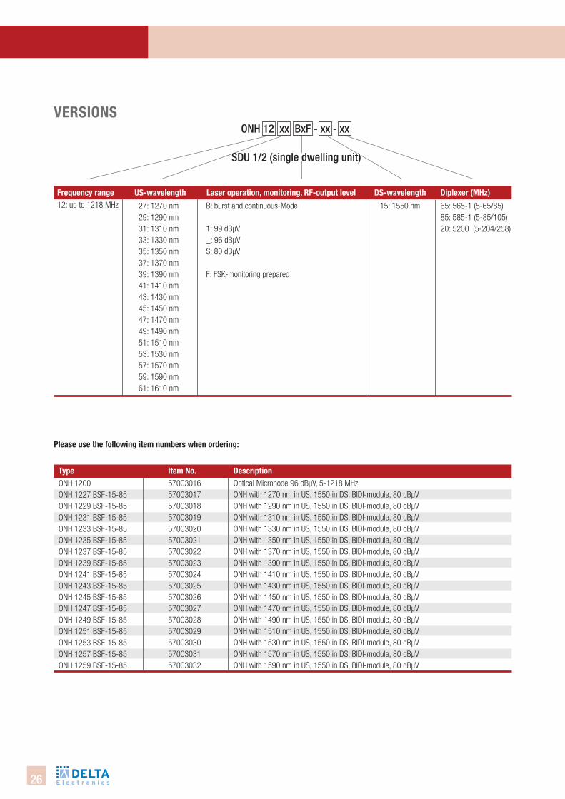
Please use the following item numbers when ordering:
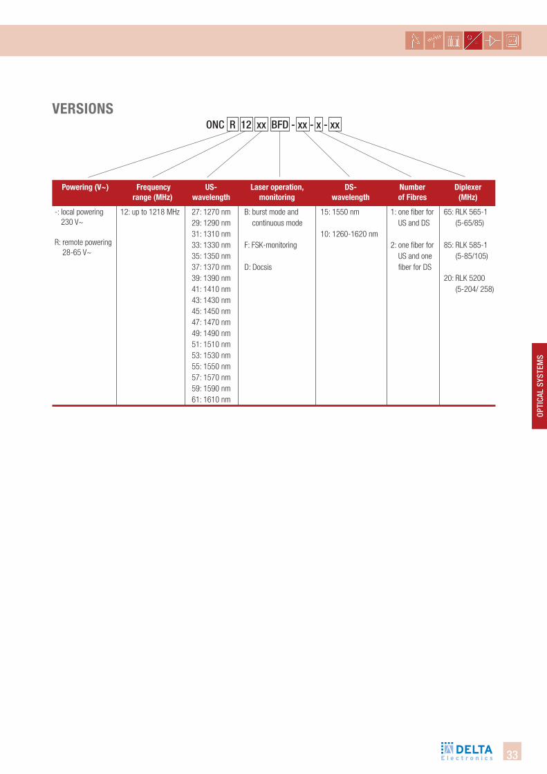
VeRsions
frequency range Us-wavelength laser operation, monitoring, Rf-output level ds-wavelength diplexer (Mhz) 12: up to 1218 MHz 27: 1270 nm
29: 1290 nm31: 1310 nm33: 1330 nm35: 1350 nm37: 1370 nm39: 1390 nm41: 1410 nm43: 1430 nm45: 1450 nm47: 1470 nm49: 1490 nm51: 1510 nm53: 1530 nm57: 1570 nm59: 1590 nm61: 1610 nm
B: burst and continuous-Mode
1: 99 dBµV_: 96 dBµVS: 80 dBµV
F: FSK-monitoring prepared
15: 1550 nm 65: 565-1 (5-65/85) 85: 585-1 (5-85/105)20: 5200 (5-204/258)
type item no. descriptionONH 1200ONH 1227 BSF-15-85ONH 1229 BSF-15-85ONH 1231 BSF-15-85ONH 1233 BSF-15-85ONH 1235 BSF-15-85ONH 1237 BSF-15-85ONH 1239 BSF-15-85ONH 1241 BSF-15-85ONH 1243 BSF-15-85ONH 1245 BSF-15-85ONH 1247 BSF-15-85ONH 1249 BSF-15-85ONH 1251 BSF-15-85ONH 1253 BSF-15-85ONH 1257 BSF-15-85ONH 1259 BSF-15-85
5700301657003017570030185700301957003020570030215700302257003023570030245700302557003026570030275700302857003029570030305700303157003032
Optical Micronode 96 dBµV, 5-1218 MHzONH with 1270 nm in US, 1550 in DS, BIDI-module, 80 dBµVONH with 1290 nm in US, 1550 in DS, BIDI-module, 80 dBµVONH with 1310 nm in US, 1550 in DS, BIDI-module, 80 dBµVONH with 1330 nm in US, 1550 in DS, BIDI-module, 80 dBµVONH with 1350 nm in US, 1550 in DS, BIDI-module, 80 dBµVONH with 1370 nm in US, 1550 in DS, BIDI-module, 80 dBµVONH with 1390 nm in US, 1550 in DS, BIDI-module, 80 dBµVONH with 1410 nm in US, 1550 in DS, BIDI-module, 80 dBµVONH with 1430 nm in US, 1550 in DS, BIDI-module, 80 dBµVONH with 1450 nm in US, 1550 in DS, BIDI-module, 80 dBµVONH with 1470 nm in US, 1550 in DS, BIDI-module, 80 dBµVONH with 1490 nm in US, 1550 in DS, BIDI-module, 80 dBµVONH with 1510 nm in US, 1550 in DS, BIDI-module, 80 dBµVONH with 1530 nm in US, 1550 in DS, BIDI-module, 80 dBµVONH with 1570 nm in US, 1550 in DS, BIDI-module, 80 dBµVONH with 1590 nm in US, 1550 in DS, BIDI-module, 80 dBµV
SDu 1/2 (single dwelling unit)
OnH 12 xx bxF - xx - xx
27
Opti
cal
SySt
emS
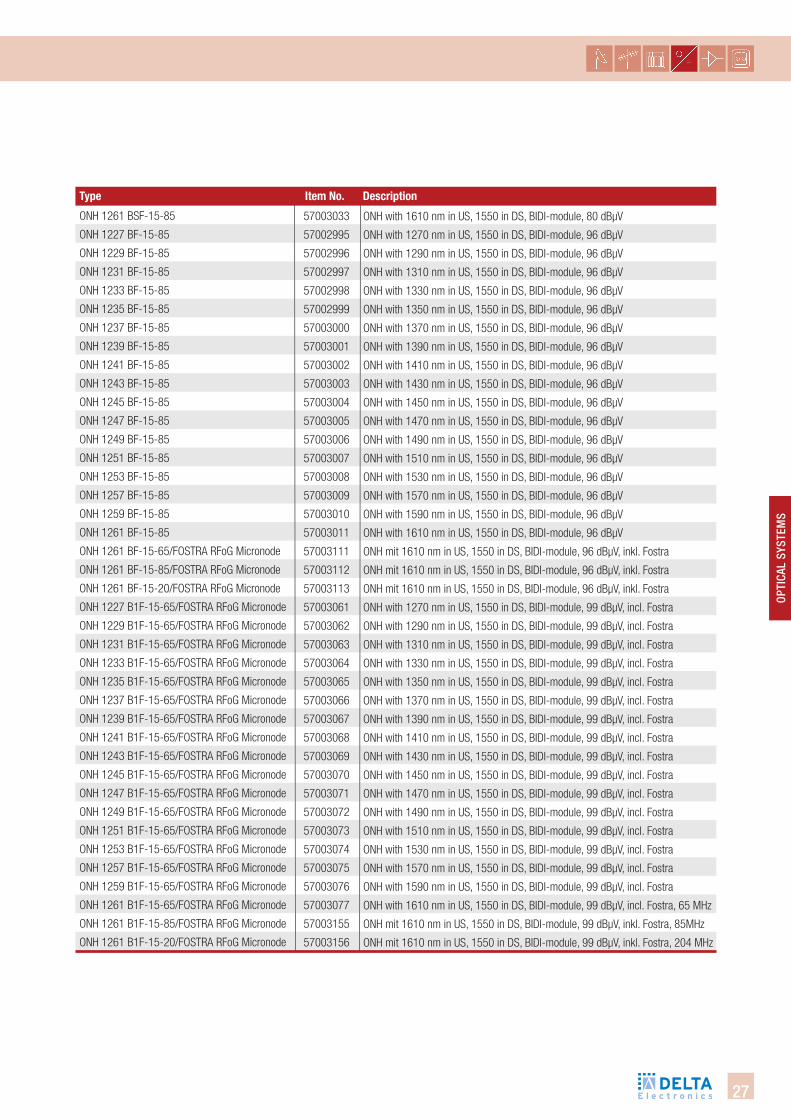
ONH 1261 BSF-15-85
ONH 1227 BF-15-85
ONH 1229 BF-15-85
ONH 1231 BF-15-85
ONH 1233 BF-15-85
ONH 1235 BF-15-85
ONH 1237 BF-15-85
ONH 1239 BF-15-85
ONH 1241 BF-15-85
ONH 1243 BF-15-85
ONH 1245 BF-15-85
ONH 1247 BF-15-85
ONH 1249 BF-15-85
ONH 1251 BF-15-85
ONH 1253 BF-15-85
ONH 1257 BF-15-85
ONH 1259 BF-15-85
ONH 1261 BF-15-85
ONH 1261 BF-15-65/FOSTRA RFoG Micronode
ONH 1261 BF-15-85/FOSTRA RFoG Micronode
ONH 1261 BF-15-20/FOSTRA RFoG Micronode
ONH 1227 B1F-15-65/FOSTRA RFoG Micronode
ONH 1229 B1F-15-65/FOSTRA RFoG Micronode
ONH 1231 B1F-15-65/FOSTRA RFoG Micronode
ONH 1233 B1F-15-65/FOSTRA RFoG Micronode
ONH 1235 B1F-15-65/FOSTRA RFoG Micronode
ONH 1237 B1F-15-65/FOSTRA RFoG Micronode
ONH 1239 B1F-15-65/FOSTRA RFoG Micronode
ONH 1241 B1F-15-65/FOSTRA RFoG Micronode
ONH 1243 B1F-15-65/FOSTRA RFoG Micronode
ONH 1245 B1F-15-65/FOSTRA RFoG Micronode
ONH 1247 B1F-15-65/FOSTRA RFoG Micronode
ONH 1249 B1F-15-65/FOSTRA RFoG Micronode
ONH 1251 B1F-15-65/FOSTRA RFoG Micronode
ONH 1253 B1F-15-65/FOSTRA RFoG Micronode
ONH 1257 B1F-15-65/FOSTRA RFoG Micronode
ONH 1259 B1F-15-65/FOSTRA RFoG Micronode
ONH 1261 B1F-15-65/FOSTRA RFoG Micronode
ONH 1261 B1F-15-85/FOSTRA RFoG Micronode
ONH 1261 B1F-15-20/FOSTRA RFoG Micronode
57003033
57002995
57002996
57002997
57002998
57002999
57003000
57003001
57003002
57003003
57003004
57003005
57003006
57003007
57003008
57003009
57003010
57003011
57003111
57003112
57003113
57003061
57003062
57003063
57003064
57003065
57003066
57003067
57003068
57003069
57003070
57003071
57003072
57003073
57003074
57003075
57003076
57003077
57003155
57003156
ONH with 1610 nm in US, 1550 in DS, BIDI-module, 80 dBµV
ONH with 1270 nm in US, 1550 in DS, BIDI-module, 96 dBµV
ONH with 1290 nm in US, 1550 in DS, BIDI-module, 96 dBµV
ONH with 1310 nm in US, 1550 in DS, BIDI-module, 96 dBµV
ONH with 1330 nm in US, 1550 in DS, BIDI-module, 96 dBµV
ONH with 1350 nm in US, 1550 in DS, BIDI-module, 96 dBµV
ONH with 1370 nm in US, 1550 in DS, BIDI-module, 96 dBµV
ONH with 1390 nm in US, 1550 in DS, BIDI-module, 96 dBµV
ONH with 1410 nm in US, 1550 in DS, BIDI-module, 96 dBµV
ONH with 1430 nm in US, 1550 in DS, BIDI-module, 96 dBµV
ONH with 1450 nm in US, 1550 in DS, BIDI-module, 96 dBµV
ONH with 1470 nm in US, 1550 in DS, BIDI-module, 96 dBµV
ONH with 1490 nm in US, 1550 in DS, BIDI-module, 96 dBµV
ONH with 1510 nm in US, 1550 in DS, BIDI-module, 96 dBµV
ONH with 1530 nm in US, 1550 in DS, BIDI-module, 96 dBµV
ONH with 1570 nm in US, 1550 in DS, BIDI-module, 96 dBµV
ONH with 1590 nm in US, 1550 in DS, BIDI-module, 96 dBµV
ONH with 1610 nm in US, 1550 in DS, BIDI-module, 96 dBµV
ONH mit 1610 nm in US, 1550 in DS, BIDI-module, 96 dBµV, inkl. Fostra
ONH mit 1610 nm in US, 1550 in DS, BIDI-module, 96 dBµV, inkl. Fostra
ONH mit 1610 nm in US, 1550 in DS, BIDI-module, 96 dBµV, inkl. Fostra
ONH with 1270 nm in US, 1550 in DS, BIDI-module, 99 dBµV, incl. Fostra
ONH with 1290 nm in US, 1550 in DS, BIDI-module, 99 dBµV, incl. Fostra
ONH with 1310 nm in US, 1550 in DS, BIDI-module, 99 dBµV, incl. Fostra
ONH with 1330 nm in US, 1550 in DS, BIDI-module, 99 dBµV, incl. Fostra
ONH with 1350 nm in US, 1550 in DS, BIDI-module, 99 dBµV, incl. Fostra
ONH with 1370 nm in US, 1550 in DS, BIDI-module, 99 dBµV, incl. Fostra
ONH with 1390 nm in US, 1550 in DS, BIDI-module, 99 dBµV, incl. Fostra
ONH with 1410 nm in US, 1550 in DS, BIDI-module, 99 dBµV, incl. Fostra
ONH with 1430 nm in US, 1550 in DS, BIDI-module, 99 dBµV, incl. Fostra
ONH with 1450 nm in US, 1550 in DS, BIDI-module, 99 dBµV, incl. Fostra
ONH with 1470 nm in US, 1550 in DS, BIDI-module, 99 dBµV, incl. Fostra
ONH with 1490 nm in US, 1550 in DS, BIDI-module, 99 dBµV, incl. Fostra
ONH with 1510 nm in US, 1550 in DS, BIDI-module, 99 dBµV, incl. Fostra
ONH with 1530 nm in US, 1550 in DS, BIDI-module, 99 dBµV, incl. Fostra
ONH with 1570 nm in US, 1550 in DS, BIDI-module, 99 dBµV, incl. Fostra
ONH with 1590 nm in US, 1550 in DS, BIDI-module, 99 dBµV, incl. Fostra
ONH with 1610 nm in US, 1550 in DS, BIDI-module, 99 dBµV, incl. Fostra, 65 MHz
ONH mit 1610 nm in US, 1550 in DS, BIDI-module, 99 dBµV, inkl. Fostra, 85MHz
ONH mit 1610 nm in US, 1550 in DS, BIDI-module, 99 dBµV, inkl. Fostra, 204 MHz
type item no. description
28
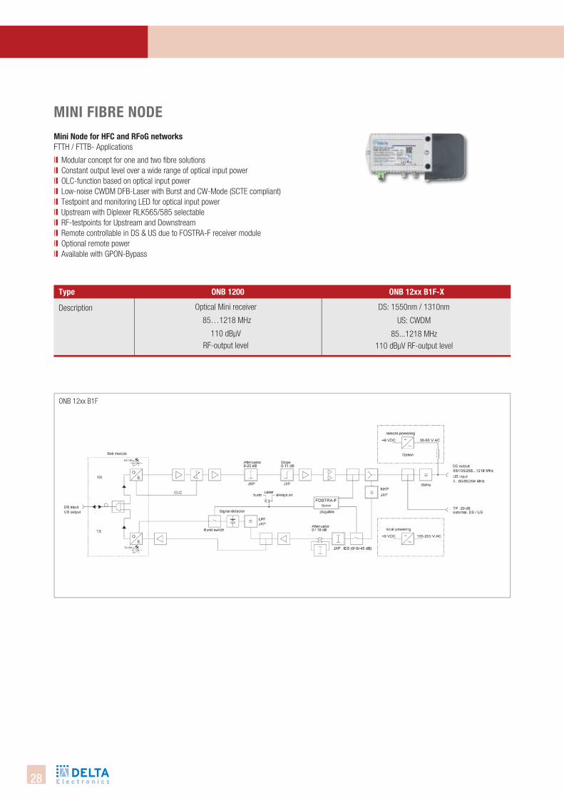
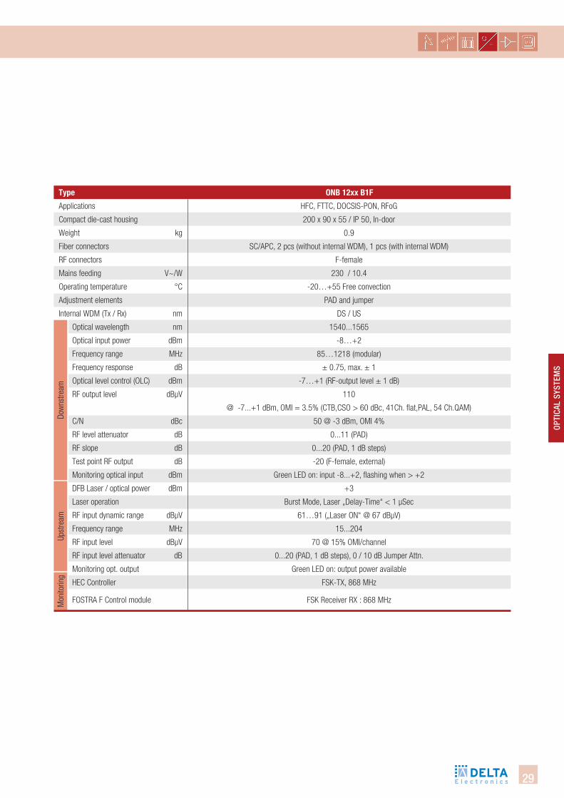
ONB 12xx B1F
type onb 1200 onb 12xx b1f-X
Mini fibRe nodeMini node for hfc and Rfog networksFTTH / FTTB- Applications
ll Modular concept for one and two fibre solutionsll Constant output level over a wide range of optical input powerll OLC-function based on optical input powerll Low-noise CWDM DFB-Laser with Burst and CW-Mode (SCTE compliant)ll Testpoint and monitoring LED for optical input powerll Upstream with Diplexer RLK565/585 selectablell RF-testpoints for Upstream and Downstreamll Remote controllable in DS & US due to FOSTRA-F receiver module ll Optional remote powerll Available with GPON-Bypass
Description Optical Mini receiver
85…1218 MHz
110 dBµV RF-output level
DS: 1550nm / 1310nm
US: CWDM
85...1218 MHz110 dBµV RF-output level
29
Opti
cal
SySt
emS
Upst
ream
Dow
nstre
amM
onito
ring
type
Applications
Compact die-cast housing
Weight kg
Fiber connectors
RF connectors
Mains feeding V~/W
Operating temperature °C
Adjustment elements
Internal WDM (Tx / Rx) nm
Optical wavelength nm
Optical input power dBm
Frequency range MHz
Frequency response dB
Optical level control (OLC) dBm
RF output level dBµV
C/N dBc
RF level attenuator dB
RF slope dB
Test point RF output dB
Monitoring optical input dBm
DFB Laser / optical power dBm
Laser operation
RF input dynamic range dBµV
Frequency range MHz
RF input level dBµV
RF input level attenuator dB
Monitoring opt. output
HEC Controller
FOSTRA F Control module
onb 12xx b1f
HFC, FTTC, DOCSIS-PON, RFoG
200 x 90 x 55 / IP 50, In-door
0.9
SC/APC, 2 pcs (without internal WDM), 1 pcs (with internal WDM)
F-female
230 / 10.4
-20…+55 Free convection
PAD and jumper
DS / US
1540...1565
-8…+2
85…1218 (modular)
± 0.75, max. ± 1
-7…+1 (RF-output level ± 1 dB)
110
@ -7...+1 dBm, OMI = 3.5% (CTB,CSO > 60 dBc, 41Ch. flat,PAL, 54 Ch.QAM)
50 @ -3 dBm, OMI 4%
0...11 (PAD)
0...20 (PAD, 1 dB steps)
-20 (F-female, external)
Green LED on: input -8...+2, flashing when > +2
+3
Burst Mode, Laser „Delay-Time“ < 1 µSec
61…91 („Laser ON“ @ 67 dBµV)
15...204
70 @ 15% OMI/channel
0...20 (PAD, 1 dB steps), 0 / 10 dB Jumper Attn.
Green LED on: output power available
FSK-TX, 868 MHz
FSK Receiver RX : 868 MHz
30
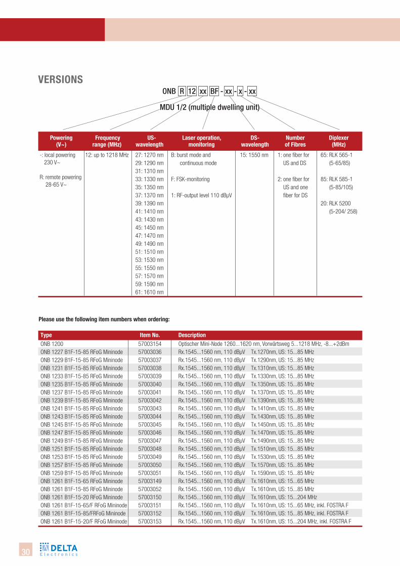
Please use the following item numbers when ordering:
VeRsions
12: up to 1218 MHz B: burst mode and continuous mode
F: FSK-monitoring
1: RF-output level 110 dBμV
15: 1550 nm27: 1270 nm29: 1290 nm31: 1310 nm33: 1330 nm35: 1350 nm37: 1370 nm39: 1390 nm41: 1410 nm43: 1430 nm45: 1450 nm47: 1470 nm49: 1490 nm51: 1510 nm53: 1530 nm55: 1550 nm57: 1570 nm59: 1590 nm61: 1610 nm
diplexer (Mhz)
Powering (V~)
frequencyrange (Mhz)
Us- wavelength
laser operation, monitoring
ds- wavelength
number of fibres
1: one fiber for US and DS
2: one fiber for US and one fiber for DS
-: local powering 230 V~
R: remote powering 28-65 V~
65: RLK 565-1 (5-65/85)
85: RLK 585-1 (5-85/105)
20: RLK 5200 (5-204/ 258)
ONB 1200ONB 1227 B1F-15-85 RFoG MininodeONB 1229 B1F-15-85 RFoG MininodeONB 1231 B1F-15-85 RFoG MininodeONB 1233 B1F-15-85 RFoG MininodeONB 1235 B1F-15-85 RFoG MininodeONB 1237 B1F-15-85 RFoG MininodeONB 1239 B1F-15-85 RFoG MininodeONB 1241 B1F-15-85 RFoG MininodeONB 1243 B1F-15-85 RFoG MininodeONB 1245 B1F-15-85 RFoG MininodeONB 1247 B1F-15-85 RFoG MininodeONB 1249 B1F-15-85 RFoG MininodeONB 1251 B1F-15-85 RFoG MininodeONB 1253 B1F-15-85 RFoG MininodeONB 1257 B1F-15-85 RFoG MininodeONB 1259 B1F-15-85 RFoG MininodeONB 1261 B1F-15-65 RFoG MininodeONB 1261 B1F-15-85 RFoG MininodeONB 1261 B1F-15-20 RFoG MininodeONB 1261 B1F-15-65/F RFoG MininodeONB 1261 B1F-15-85/FRFoG MininodeONB 1261 B1F-15-20/F RFoG Mininode
5700315457003036570030375700303857003039570030405700304157003042570030435700304457003045570030465700304757003048570030495700305057003051570031495700305257003150570031515700315257003153
Optischer Mini-Node 1260...1620 nm, Vorwärtsweg 5...1218 MHz, -8...+2dBmRx.1545...1560 nm, 110 dBµV Tx.1270nm, US: 15...85 MHzRx.1545...1560 nm, 110 dBµV Tx.1290nm, US: 15...85 MHzRx.1545...1560 nm, 110 dBµV Tx.1310nm, US: 15...85 MHzRx.1545...1560 nm, 110 dBµV Tx.1330nm, US: 15...85 MHzRx.1545...1560 nm, 110 dBµV Tx.1350nm, US: 15...85 MHzRx.1545...1560 nm, 110 dBµV Tx.1370nm, US: 15...85 MHzRx.1545...1560 nm, 110 dBµV Tx.1390nm, US: 15...85 MHzRx.1545...1560 nm, 110 dBµV Tx.1410nm, US: 15...85 MHzRx.1545...1560 nm, 110 dBµV Tx.1430nm, US: 15...85 MHzRx.1545...1560 nm, 110 dBµV Tx.1450nm, US: 15...85 MHzRx.1545...1560 nm, 110 dBµV Tx.1470nm, US: 15...85 MHzRx.1545...1560 nm, 110 dBµV Tx.1490nm, US: 15...85 MHzRx.1545...1560 nm, 110 dBµV Tx.1510nm, US: 15...85 MHzRx.1545...1560 nm, 110 dBµV Tx.1530nm, US: 15...85 MHzRx.1545...1560 nm, 110 dBµV Tx.1570nm, US: 15...85 MHzRx.1545...1560 nm, 110 dBµV Tx.1590nm, US: 15...85 MHzRx.1545...1560 nm, 110 dBµV Tx.1610nm, US: 15...65 MHzRx.1545...1560 nm, 110 dBµV Tx.1610nm, US: 15...85 MHzRx.1545...1560 nm, 110 dBµV Tx.1610nm, US: 15...204 MHzRx.1545...1560 nm, 110 dBµV Tx.1610nm, US: 15...65 MHz, inkl. FOSTRA FRx.1545...1560 nm, 110 dBµV Tx.1610nm, US: 15...85 MHz, inkl. FOSTRA FRx.1545...1560 nm, 110 dBµV Tx.1610nm, US: 15...204 MHz, inkl. FOSTRA F
mDu 1/2 (multiple dwelling unit)
Onb R 12 xx bF - xx - x - xx
type item no. description
31
OPti
cAl
SYSt
emS
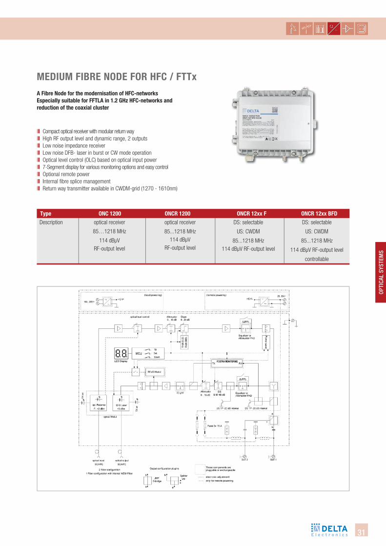
Description optical receiver
85…1218 MHz
114 dBµV RF-output level
optical receiver
85...1218 MHz114 dBµV
RF-output level
DS: selectable
US: CWDM
85...1218 MHz
114 dBµV RF-output level
controllable
DS: selectable
US: CWDM
85...1218 MHz114 dBµV RF-output level
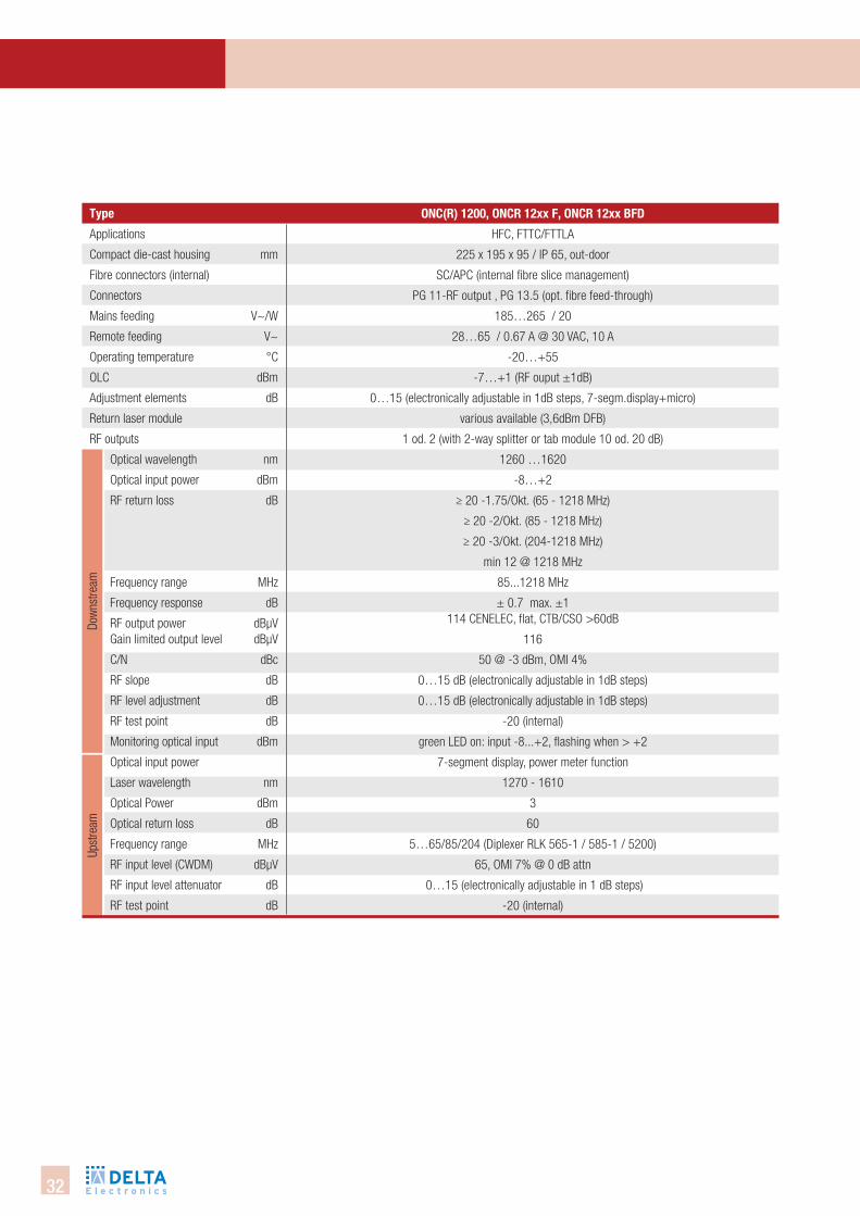
type onc 1200 oncR 1200 oncR 12xx f oncR 12xx bfd
MediUM fibRe node foR hfc / fttxa fibre node for the modernisation of hfc-networksespecially suitable for fftla in 1.2 ghz hfc-networks and reduction of the coaxial cluster
ll Compact optical receiver with modular return way ll High RF output level and dynamic range, 2 outputs ll Low noise impedance receiver ll Low noise DFB- laser in burst or CW mode operation ll Optical level control (OLC) based on optical input power ll 7-Segment display for various monitoring options and easy controlll Optional remote powerll Internal fibre splice managementll Return way transmitter available in CWDM-grid (1270 - 1610nm)
32
Upst
ream
Dow
nstre
am
type
Applications
Compact die-cast housing mm
Fibre connectors (internal)
Connectors
Mains feeding V~/W
Remote feeding V~
Operating temperature °C
OLC dBm
Adjustment elements dB
Return laser module
RF outputs
Optical wavelength nm
Optical input power dBm
RF return loss dB
Frequency range MHz
Frequency response dB
RF output power dBµVGain limited output level dBµV
C/N dBc
RF slope dB
RF level adjustment dB
RF test point dB
Monitoring optical input dBm
Optical input power
Laser wavelength nm
Optical Power dBm
Optical return loss dB
Frequency range MHz
RF input level (CWDM) dBµV
RF input level attenuator dB
RF test point dB
onc(R) 1200, oncR 12xx f, oncR 12xx bfd
HFC, FTTC/FTTLA
225 x 195 x 95 / IP 65, out-door
SC/APC (internal fibre slice management)
PG 11-RF output , PG 13.5 (opt. fibre feed-through)
185…265 / 20
28…65 / 0.67 A @ 30 VAC, 10 A
-20…+55
-7…+1 (RF ouput ±1dB)
0…15 (electronically adjustable in 1dB steps, 7-segm.display+micro)
various available (3,6dBm DFB)
1 od. 2 (with 2-way splitter or tab module 10 od. 20 dB)
1260 …1620
-8…+2
≥ 20 -1.75/Okt. (65 - 1218 MHz)
≥ 20 -2/Okt. (85 - 1218 MHz)
≥ 20 -3/Okt. (204-1218 MHz)
min 12 @ 1218 MHz
85...1218 MHz
± 0.7 max. ±1 114 CENELEC, flat, CTB/CSO >60dB
116
50 @ -3 dBm, OMI 4%
0…15 dB (electronically adjustable in 1dB steps)
0…15 dB (electronically adjustable in 1dB steps)
-20 (internal)
green LED on: input -8...+2, flashing when > +2
7-segment display, power meter function
1270 - 1610
3
60
5…65/85/204 (Diplexer RLK 565-1 / 585-1 / 5200)
65, OMI 7% @ 0 dB attn
0…15 (electronically adjustable in 1 dB steps)
-20 (internal)
33
Opti
cal
SySt
emS
VeRsions
12: up to 1218 MHz B: burst mode and continuous mode
F: FSK-monitoring
D: Docsis
15: 1550 nm
10: 1260-1620 nm
27: 1270 nm29: 1290 nm31: 1310 nm33: 1330 nm35: 1350 nm37: 1370 nm39: 1390 nm41: 1410 nm43: 1430 nm45: 1450 nm47: 1470 nm49: 1490 nm51: 1510 nm53: 1530 nm55: 1550 nm57: 1570 nm59: 1590 nm61: 1610 nm
diplexer (Mhz)
Powering (V~) frequencyrange (Mhz)
Us- wavelength
laser operation, monitoring
ds- wavelength
number of fibres
1: one fiber for US and DS
2: one fiber for US and one fiber for DS
-: local powering 230 V~
R: remote powering 28-65 V~
65: RLK 565-1 (5-65/85)
85: RLK 585-1 (5-85/105)
20: RLK 5200 (5-204/ 258)
Onc R 12 xx bFD - xx - x - xx
34
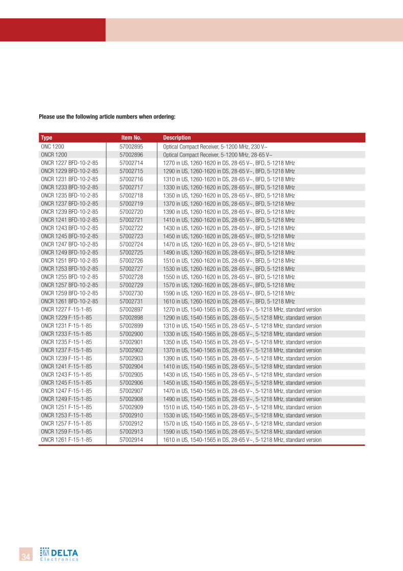
Optical Compact Receiver, 5-1200 MHz, 230 V~Optical Compact Receiver, 5-1200 MHz, 28-65 V~1270 in US, 1260-1620 in DS, 28-65 V~, BFD, 5-1218 MHz1290 in US, 1260-1620 in DS, 28-65 V~, BFD, 5-1218 MHz1310 in US, 1260-1620 in DS, 28-65 V~, BFD, 5-1218 MHz1330 in US, 1260-1620 in DS, 28-65 V~, BFD, 5-1218 MHz1350 in US, 1260-1620 in DS, 28-65 V~, BFD, 5-1218 MHz1370 in US, 1260-1620 in DS, 28-65 V~, BFD, 5-1218 MHz1390 in US, 1260-1620 in DS, 28-65 V~, BFD, 5-1218 MHz1410 in US, 1260-1620 in DS, 28-65 V~, BFD, 5-1218 MHz1430 in US, 1260-1620 in DS, 28-65 V~, BFD, 5-1218 MHz1450 in US, 1260-1620 in DS, 28-65 V~, BFD, 5-1218 MHz1470 in US, 1260-1620 in DS, 28-65 V~, BFD, 5-1218 MHz1490 in US, 1260-1620 in DS, 28-65 V~, BFD, 5-1218 MHz1510 in US, 1260-1620 in DS, 28-65 V~, BFD, 5-1218 MHz1530 in US, 1260-1620 in DS, 28-65 V~, BFD, 5-1218 MHz1550 in US, 1260-1620 in DS, 28-65 V~, BFD, 5-1218 MHz1570 in US, 1260-1620 in DS, 28-65 V~, BFD, 5-1218 MHz1590 in US, 1260-1620 in DS, 28-65 V~, BFD, 5-1218 MHz1610 in US, 1260-1620 in DS, 28-65 V~, BFD, 5-1218 MHz1270 in US, 1540-1565 in DS, 28-65 V~, 5-1218 MHz, standard version 1290 in US, 1540-1565 in DS, 28-65 V~, 5-1218 MHz, standard version 1310 in US, 1540-1565 in DS, 28-65 V~, 5-1218 MHz, standard version 1330 in US, 1540-1565 in DS, 28-65 V~, 5-1218 MHz, standard version1350 in US, 1540-1565 in DS, 28-65 V~, 5-1218 MHz, standard version 1370 in US, 1540-1565 in DS, 28-65 V~, 5-1218 MHz, standard version 1390 in US, 1540-1565 in DS, 28-65 V~, 5-1218 MHz, standard version 1410 in US, 1540-1565 in DS, 28-65 V~, 5-1218 MHz, standard version 1430 in US, 1540-1565 in DS, 28-65 V~, 5-1218 MHz, standard version 1450 in US, 1540-1565 in DS, 28-65 V~, 5-1218 MHz, standard version 1470 in US, 1540-1565 in DS, 28-65 V~, 5-1218 MHz, standard version 1490 in US, 1540-1565 in DS, 28-65 V~, 5-1218 MHz, standard version 1510 in US, 1540-1565 in DS, 28-65 V~, 5-1218 MHz, standard version 1530 in US, 1540-1565 in DS, 28-65 V~, 5-1218 MHz, standard version 1570 in US, 1540-1565 in DS, 28-65 V~, 5-1218 MHz, standard version 1590 in US, 1540-1565 in DS, 28-65 V~, 5-1218 MHz, standard version 1610 in US, 1540-1565 in DS, 28-65 V~, 5-1218 MHz, standard version
57002895570028965700271457002715570027165700271757002718570027195700272057002721570027225700272357002724570027255700272657002727570027285700272957002730570027315700289757002898570028995700290057002901570029025700290357002904570029055700290657002907570029085700290957002910570029125700291357002914
ONC 1200ONCR 1200 ONCR 1227 BFD-10-2-85ONCR 1229 BFD-10-2-85ONCR 1231 BFD-10-2-85ONCR 1233 BFD-10-2-85ONCR 1235 BFD-10-2-85ONCR 1237 BFD-10-2-85ONCR 1239 BFD-10-2-85ONCR 1241 BFD-10-2-85ONCR 1243 BFD-10-2-85ONCR 1245 BFD-10-2-85ONCR 1247 BFD-10-2-85ONCR 1249 BFD-10-2-85ONCR 1251 BFD-10-2-85ONCR 1253 BFD-10-2-85ONCR 1255 BFD-10-2-85ONCR 1257 BFD-10-2-85ONCR 1259 BFD-10-2-85ONCR 1261 BFD-10-2-85ONCR 1227 F-15-1-85ONCR 1229 F-15-1-85ONCR 1231 F-15-1-85ONCR 1233 F-15-1-85ONCR 1235 F-15-1-85ONCR 1237 F-15-1-85ONCR 1239 F-15-1-85ONCR 1241 F-15-1-85ONCR 1243 F-15-1-85ONCR 1245 F-15-1-85ONCR 1247 F-15-1-85ONCR 1249 F-15-1-85ONCR 1251 F-15-1-85ONCR 1253 F-15-1-85ONCR 1257 F-15-1-85ONCR 1259 F-15-1-85ONCR 1261 F-15-1-85
Please use the following article numbers when ordering:
type item no. description
35
OPti
cAl
SYSt
emS
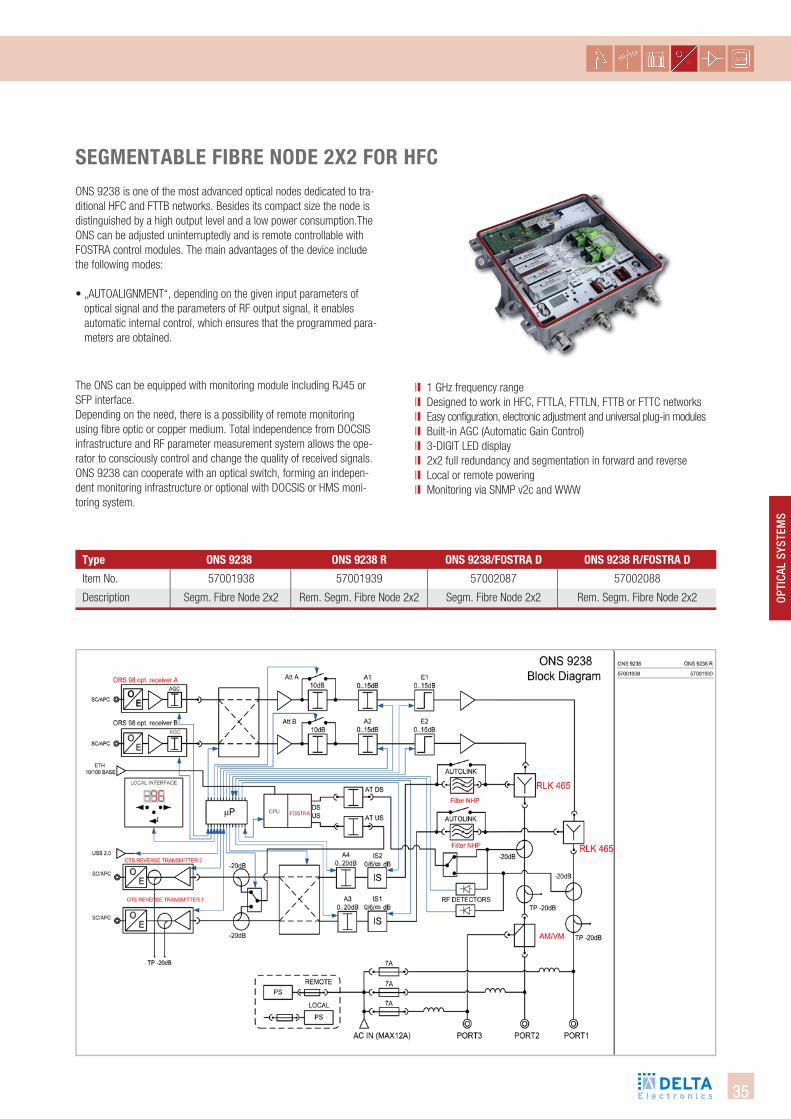
type ons 9238 ons 9238 R ons 9238/fostRa d ons 9238 R/fostRa d
segMentable fibRe node 2X2 foR hfcONS 9238 is one of the most advanced optical nodes dedicated to tra-ditional HFC and FTTB networks. Besides its compact size the node is distinguished by a high output level and a low power consumption.The ONS can be adjusted uninterruptedly and is remote controllable with FOSTRA control modules. The main advantages of the device include the following modes:
• „AUTOALIGNMENT“, depending on the given input parameters of optical signal and the parameters of RF output signal, it enables automatic internal control, which ensures that the programmed para-meters are obtained.
The ONS can be equipped with monitoring module including RJ45 or SFP interface. Depending on the need, there is a possibility of remote monitoring using fibre optic or copper medium. Total independence from DOCSIS infrastructure and RF parameter measurement system allows the ope-rator to consciously control and change the quality of received signals. ONS 9238 can cooperate with an optical switch, forming an indepen-dent monitoring infrastructure or optional with DOCSIS or HMS moni-toring system.
ll 1 GHz frequency range ll Designed to work in HFC, FTTLA, FTTLN, FTTB or FTTC networksll Easy configuration, electronic adjustment and universal plug-in modules ll Built-in AGC (Automatic Gain Control) ll 3-DIGIT LED display ll 2x2 full redundancy and segmentation in forward and reverse ll Local or remote powering ll Monitoring via SNMP v2c and WWW
Item No.
Description
57001938
Segm. Fibre Node 2x2
57001939
Rem. Segm. Fibre Node 2x2
57002087
Segm. Fibre Node 2x2
57002088
Rem. Segm. Fibre Node 2x2
36
Upst
ream
TX
Dow
nstre
am R
X
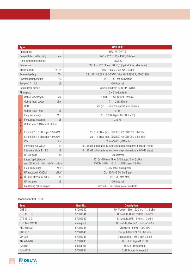
type ons 9238
type
Applications
Compact die-cast housing mm
Fibre connectors (internal)
Connectors
Mains feeding V~/W
Remote feeding V~
Operating temperature °C
Testpoint A1, A2 dB
Return laser module
RF outputs
Optical wavelength nm
Optical input power dBm
OLC
Optical return loss dB
Frequency range MHz
Frequency response dB
Output level 1310nm @ -3 dBm E1 and E2 = 6 dB slope, 3,5% OMI
E1 and E2 = 6 dB slope, 4,0% OMI
C/N dBc
Interstage Att. A1, A2 dB
Interstage slope E1, E2 dB
RF test point dB
Laser / optical power (e.g. OTS 1610 D, 1610 nm DFB + 3 dBm)
Frequency range MHz
RF input level (CWDM) dBµV
RF level attenuator A3, 4 dB
RF test point dB
Monitoring optical output
HFC, FTTC/FTTB
245 x 207 x 125 / IP 65, Out-door
SC/APC
PG 11 or 5/8“ RF out, PG 13,5 (Optical fibre cable input)
185…265 / < 35 (ONS 9238)
28…70 / 0,67 A @ 30 VAC, 10 A (ONS 9238 R, 57001939)
-20…+55, Free convection
-20 (internal)
various available (DFB, FP, CWDM)
2 x 2 (redundant)
1100 …1650 (ORS 98 module)
-7…+2 (1310nm)
Yes (-6 … +0 dBm, optical level control)
> 45
85…1006 (Diplex filter RLK 465)
± 0.75
2 x 114 dBµV (acc. CENELEC 42 CTB/CSO > 60 dBc)
2 x 116 dBµV (acc. CENELEC 42 CTB/CSO > 58 dBc)
52 @ -3 dBm, OMI 4%
0…15 dB (adjustable by electronic step attenuators in 0,5 dB steps)
0…15 dB (adjustable by electronic step attenuators in 0,5 dB steps)
-20 (internal)
1310/1610 nm: FP or DFB-Laser / 0 or 3 dBm CWDM 1470…1610 nm: DFB-Laser / 3 dBm
5…65 (other on request)
OMI 10 % @ 70, 0 dB attn
0…20 (1 dB step attn.)
-20 (internal)
Green LED on: output power available
Modules for ONS 9238
ORS 98
OTS 1310 D
OTS 1610 D
OTS 1xxx CWDM
RLK 465 (2x)
NHP 915
VM 902
AM 9-01-10
FOSTRA D
JUM-ONS
descriptionitem no.RX-Module 1260 -1620nm, -7…2 dBm
TX-Module, DFB 1310nm, +3 dBm
TX-Module, DFB 1610nm, +3 dBm
TX-Module, CWDM 1xxxnm, +3 dBm
Diplexer 5 - 65/85-1000 MHz
Rev path filter FPA 15 - 65 MHz
Output splitter VM 2-fach 3.5 dB
Output RF Tap AM 10 dB
DOCSIS Transponder
0 dB Jumper for output 2
57001940
57001941
57001942
on request
57001945
57001946
57001947
57001948
on request
57001984
37
OPti
cAl
SYSt
emS
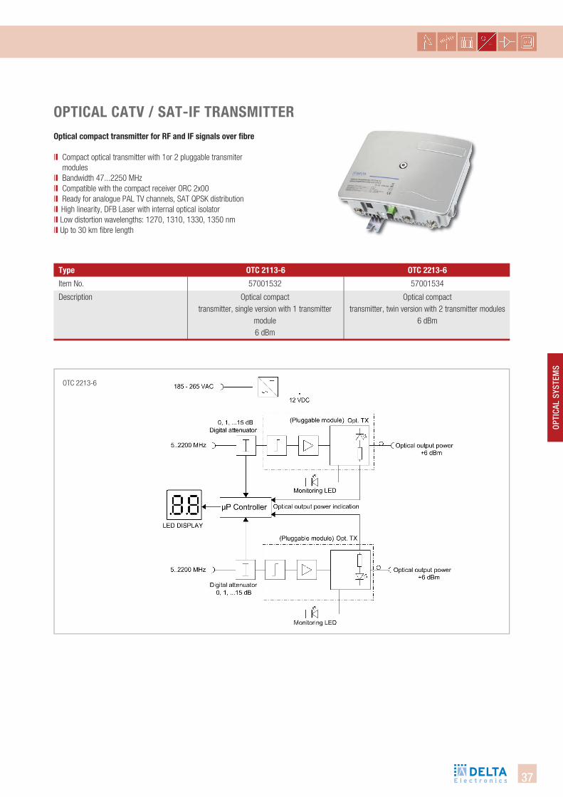
OTC 2213-6
type otc 2113-6 otc 2213-6
oPtical catV / sat-if tRansMitteRoptical compact transmitter for Rf and if signals over fibre
ll Compact optical transmitter with 1or 2 pluggable transmiter modules
ll Bandwidth 47...2250 MHzll Compatible with the compact receiver ORC 2x00 ll Ready for analogue PAL TV channels, SAT QPSK distribution ll High linearity, DFB Laser with internal optical isolatorll Low distortion wavelengths: 1270, 1310, 1330, 1350 nmll Up to 30 km fibre length
Item No.
Description
57001532
Optical compact transmitter, single version with 1 transmitter
module 6 dBm
57001534
Optical compact transmitter, twin version with 2 transmitter modules
6 dBm

38
type otc 2x13-6
Applications
Operation wavelength (λ) nm
Optical output power dBm
Laser class
RF bandwidth MHz
Frequency flatness dB
RF input level PAL dBµV
Maximum input Level dBµV
Laser type
RF return loss dB
Optical return loss dB
RF Input level attenuator dB
Monitoring optical output
optical link sat-ifOptical budget OTC2213-6 QPSK dB
Fibre connectors
RF connectors
LNB-power supply V/mA
Compact die-cast housing mm
Operating voltage V~
Operating temperature °C
Weight kg
CATV and SAT over fibre
1290, 1310, 1330, 1350
+6 (Indication on LED display)
1M, DIN EN 60825-1 (2008)
5 … 2250
± 0.5, 5 … 2250 MHz
76…91, ATT = 0…15 dB @ OMI 4% (OTC 2213-6)
93
un-cooled DFB
> 14, up to 2200 MHz
> 55
0…15 (Indication and Setting on LED display,1 dB steps)
Green LED on (output power available)
with ORC 2200
> 15 dB (BER degradation factor ~ 10)
SC/APC
F female
12.8 / max. 500
225 x 190 x 86
185…265
0…+55
2
39
OPti
cAl
SYSt
emS
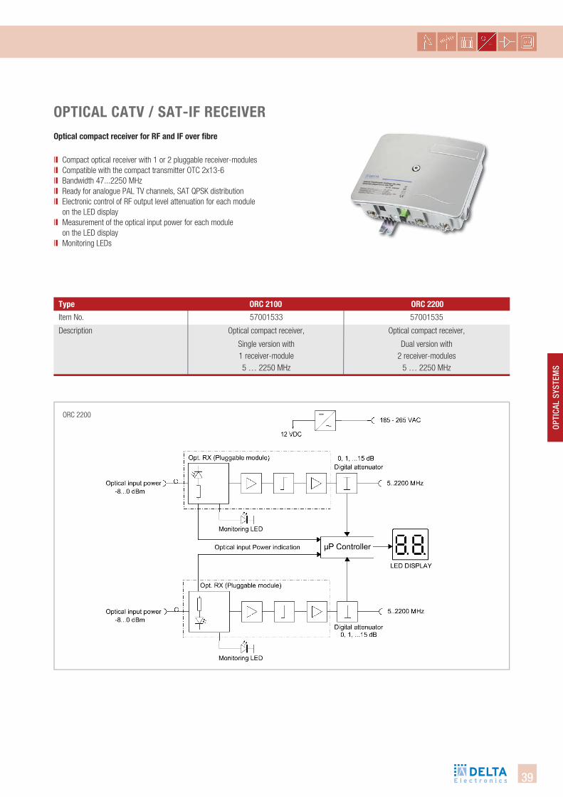
ORC 2200
type oRc 2100 oRc 2200
oPtical catV / sat-if ReceiVeR optical compact receiver for Rf and if over fibre
ll Compact optical receiver with 1 or 2 pluggable receiver-modules ll Compatible with the compact transmitter OTC 2x13-6ll Bandwidth 47...2250 MHzll Ready for analogue PAL TV channels, SAT QPSK distribution ll Electronic control of RF output level attenuation for each module
on the LED displayll Measurement of the optical input power for each module
on the LED displayll Monitoring LEDs
Item No.
Description
57001533
Optical compact receiver,
Single version with 1 receiver-module 5 … 2250 MHz
57001535
Optical compact receiver,
Dual version with 2 receiver-modules
5 … 2250 MHz
40
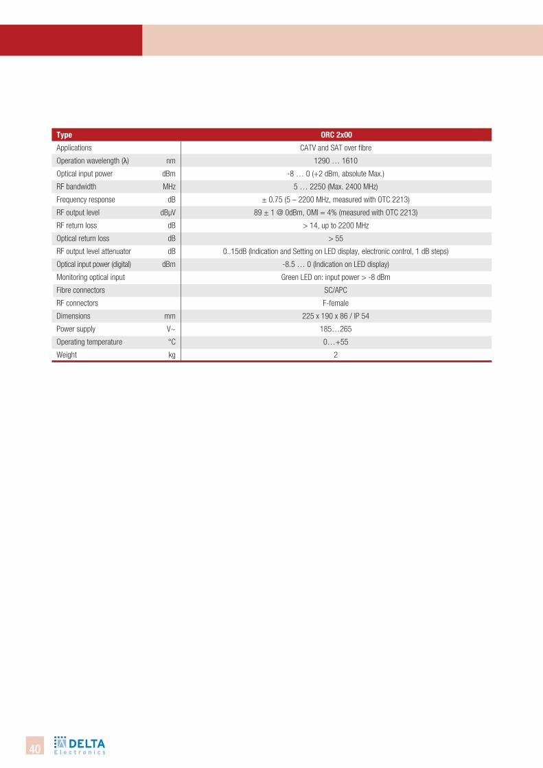
type oRc 2x00
Applications
Operation wavelength (λ) nm
Optical input power dBm
RF bandwidth MHz
Frequency response dB
RF output level dBµV
RF return loss dB
Optical return loss dB
RF output level attenuator dB
Optical input power (digital) dBm
Monitoring optical input
Fibre connectors
RF connectors
Dimensions mm
Power supply V~
Operating temperature °C
Weight kg
CATV and SAT over fibre
1290 … 1610
-8 … 0 (+2 dBm, absolute Max.)
5 … 2250 (Max. 2400 MHz)
± 0.75 (5 – 2200 MHz, measured with OTC 2213)
89 ± 1 @ 0dBm, OMI = 4% (measured with OTC 2213)
> 14, up to 2200 MHz
> 55
0..15dB (Indication and Setting on LED display, electronic control, 1 dB steps)
-8.5 … 0 (Indication on LED display)
Green LED on: input power > -8 dBm
SC/APC
F-female
225 x 190 x 86 / IP 54
185…265
0…+55
2
41
OPti
cAl
SYSt
emS
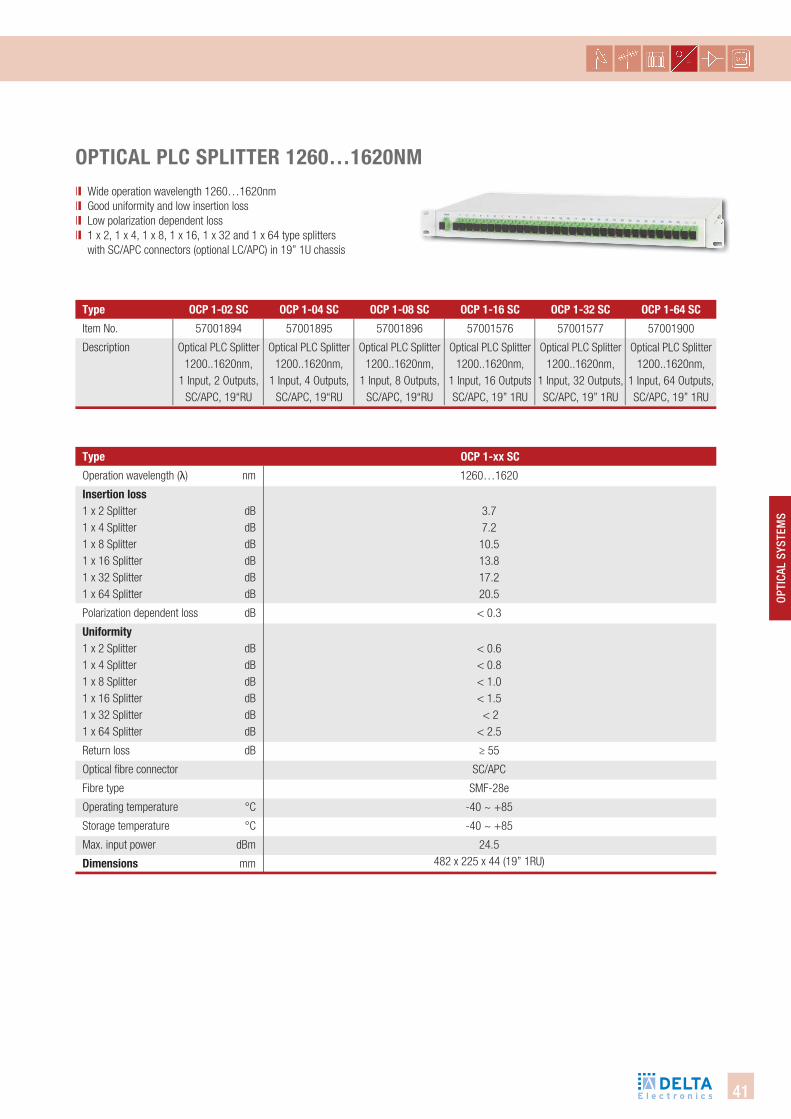
oPtical Plc sPlitteR 1260…1620nMll Wide operation wavelength 1260…1620nmll Good uniformity and low insertion lossll Low polarization dependent lossll 1 x 2, 1 x 4, 1 x 8, 1 x 16, 1 x 32 and 1 x 64 type splitters
with SC/APC connectors (optional LC/APC) in 19” 1U chassis
Item No.
Description
type ocP 1-02 sc ocP 1-04 sc ocP 1-08 sc ocP 1-16 sc ocP 1-32 sc ocP 1-64 sc
57001894
Optical PLC Splitter 1200..1620nm,
1 Input, 2 Outputs, SC/APC, 19“RU
57001895
Optical PLC Splitter 1200..1620nm,
1 Input, 4 Outputs,SC/APC, 19“RU
57001896
Optical PLC Splitter 1200..1620nm,
1 Input, 8 Outputs,SC/APC, 19“RU
57001576
Optical PLC Splitter 1200..1620nm,
1 Input, 16 Outputs SC/APC, 19” 1RU
57001577
Optical PLC Splitter 1200..1620nm,
1 Input, 32 Outputs,SC/APC, 19” 1RU
57001900
Optical PLC Splitter 1200..1620nm,
1 Input, 64 Outputs, SC/APC, 19” 1RU
Operation wavelength (λ) nm
insertion loss1 x 2 Splitter dB1 x 4 Splitter dB1 x 8 Splitter dB1 x 16 Splitter dB1 x 32 Splitter dB1 x 64 Splitter dB
Polarization dependent loss dB
Uniformity 1 x 2 Splitter dB1 x 4 Splitter dB1 x 8 Splitter dB1 x 16 Splitter dB1 x 32 Splitter dB1 x 64 Splitter dB
Return loss dB
Optical fibre connector
Fibre type
Operating temperature °C
Storage temperature °C
Max. input power dBm
dimensions mm
type ocP 1-xx sc
1260…1620
3.77.2
10.513.817.220.5
< 0.3
< 0.6< 0.8< 1.0< 1.5 < 2
< 2.5
≥ 55
SC/APC
SMF-28e
-40 ~ +85
-40 ~ +85
24.5482 x 225 x 44 (19” 1RU)
42
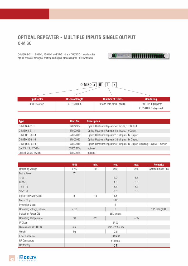
oPtical RePeateR - MUltiPle inPUts single oUtPUtO-miSO
O-MISO 4-61-1, 8-61-1, 16-61-1 and 32-61-1 is a DOCSIS 3.1 ready active optical repeater for signal splitting and signal processing for FTTx-Networks.
type item no. description
O-MISO 4-61-1
O-MISO 8-61-1
O-MISO 16-61-1
O-MISO 32-61-1
O-MISO 32-61-1 F
OA XFP 13 / 17 dBm
Optical MEMS-Switch
57002984
57002926
57002816
57002927
57002944
57002813 /
57003035
Optical Upstream Repeater 4 x Inputs, 1 x Output
Optical Upstream Repeater 8 x Inputs, 1x Output
Optical Upstream Repeater 16 x Inputs, 1x Output
Optical Upstream Repeater 32 x Inputs, 1x Output
Optical Upstream Repeater 32 x Inputs, 1x Output, including FOSTRA-F module
optional
optional
Operating Voltage
Mains Power
4-61-1
8-61-1
16-61-1
32-61-1
Length of Power Cable
Mains Plug
Protection Class
Operating Voltage, internal
Indication Power ON
Operating Temperature
IP Class
Dimensions W x H x D
Weight
Fiber Connector
RF Connectors
Conformity
Unit min. typ. max. RemarksV AC
W
m
V DC
°C
mm
kg
185
1.3
-20
265
4.5
5.0
6.3
8.5
+55
Switched mode PSU
19“ case (1RU)
IP 20
430 x 260 x 45
2.5
SC/APC
F-female
LED green
230
4.0
4.5
5.8
8.0
1.5
EURO
II
9
split factor Us-wavelength number of fibres Monitoring
4; 8; 16 or 32 61: 1610 nm 1: one fi bre for DS and US -: FOSTRA-F prepared
F: FOSTRA F integrated
O-miSO x - 61 - 1 - x
43
Opti
cal
SySt
emS
with
FOS
TRA-
F
downstream transparent
Optical Wavelength
Integrated WDM filter 1550 nm /CWDM
Attenuation
4-61-1
8-61-1
16-61-1
32-61-1
Optical Input Power
Optical Input Return Loss DS
Optical Receiver Diode Type
Decoupling Attenuation
Optical Input Power Range
Optical Output Power (total)
Mains Power
Optical wavelength
Insertion Loss
Switching Time
Unit min. typ. max. Remarks
with
EDF
Aw
ith o
ptic
al M
EMS-
Switc
h
oPtical RePeateR - MUltiPle inPUts single oUtPUttecHnicAl DAtA - DOwnStReAm
nm
dB
dBm
dB
dB
dBm
dBm
W
nm
dB
ms
1540
45
0
1240
1550
Yes
7.5
10.5
13.5
16.5
PIN
0.3
+3
17.0
2.5
0.4
2
1560
8.0
11.0
14.0
17.0
22
0.5
+6
3.0
1640
0.9
10
Laser Class 1M
Downstream: ll Transparent for 1550 nm DS signalsll Prepared for XFP EDFA-module 17 dBm optical output powerll Redundant fiber concept possible with optical MEMS-switchll Separate xPON output / xPON with RF overlay application
others on request
44
Upstream active combinerOptical Receiver Diode Type
Optical Input Wavelength
Optical Input Power
Optical Input Return Loss US
Optical Transmitter Diode Type
Optical Output Wavelength
Optical Output Power
Laser turn-on time
Frequency range
Flatness
Level Drift between Inputs
Testpoint for OMI control
Optical input dynamic range, adjustable with 10 dB Step-Att. (2dB Step)
CINR measurement *) @114 MHz 24 Ch.; QAM 64; 5.56 Msym/s
Unit min. typ. max. Remarks
oPtical RePeateR - MUltiPle inPUts single oUtPUttecHnicAl DAtA - uPStReAm
nm
dBm
dB
nm
dBm
nsec
MHz
dB
dB
dBµV
dB
dB
1240
-3
45
1605
12
75
0
40.0
PIN
DFB
1610
+3
CW
-
±0.5
±0.75
>42.0
1620
+3
1615
204
±0.75
±1.0
82
10
without 1540 - 1560
adjustable
Laser Class 1
18 CWDM - λ avail.
+6 dBm on request
continuous mode
for DOCSIS 3.1
75dBµV ≙ 6% OMI
82dBµV ≙ 15% OMI-2 dBm -> 0 dB 0 dBm -> 4 dB
+3 dBm -> 10 dBat:
MER EUT > 45.0 dBBER EUT < 1E-9
OMI Adjustment
with FOSTRA-F without FOSTRA-F
-3 ... +3 OFFdBµV
Inpu
tOu
tput
Tran
smis
sion
Cha
ract
eris
tic
upstream: ll Totally avoiding of optical interferences (OBI)ll All DOCSIS US channels on one optical CWDM wavelengthll Pluggable optical US modulell Transparent for all the adjustments set by the optical node ll High input performance from -3 to +3 dBmll OMI-Adjustment over FOSTRA-F possiblell Testpoint to measure the total electrical US signal before converting
to an optical signalll Ultra Low noise DFB-laser with isolator
fostRa-f switching options Unit function
45
Opti
cal
SySt
emS
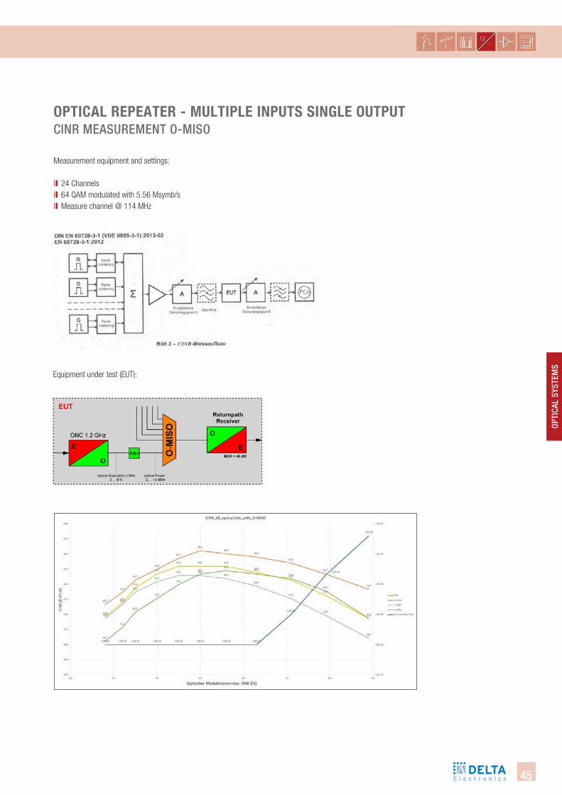
Equipment under test (EUT):
oPtical RePeateR - MUltiPle inPUts single oUtPUtcinR meASuRement O-miSO
Measurement equipment and settings:
ll 24 Channelsll 64 QAM modulated with 5.56 Msymb/sll Measure channel @ 114 MHz
46
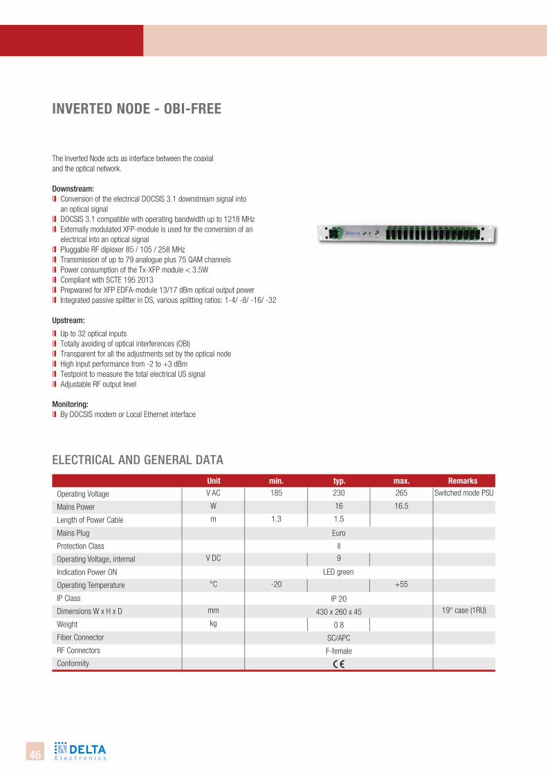
inVeRted node - obi-fRee
The Inverted Node acts as interface between the coaxial and the optical network.
Downstream: ll Conversion of the electrical DOCSIS 3.1 downstream signal into
an optical signalll DOCSIS 3.1 compatible with operating bandwidth up to 1218 MHzll Externally modulated XFP-module is used for the conversion of an
electrical into an optical signal ll Pluggable RF diplexer 85 / 105 / 258 MHzll Transmission of up to 79 analogue plus 75 QAM channelsll Power consumption of the Tx-XFP module < 3.5Wll Compliant with SCTE 195 2013ll Prepwared for XFP EDFA-module 13/17 dBm optical output powerll Integrated passive splitter in DS, various splitting ratios: 1-4/ -8/ -16/ -32
upstream:
ll Up to 32 optical inputsll Totally avoiding of optical interferences (OBI)ll Transparent for all the adjustments set by the optical node ll High input performance from -2 to +3 dBmll Testpoint to measure the total electrical US signalll Adjustable RF output level
monitoring: ll By DOCSIS modem or Local Ethernet interface
Operating Voltage
Mains Power
Length of Power Cable
Mains Plug
Protection Class
Operating Voltage, internal
Indication Power ON
Operating Temperature
IP Class
Dimensions W x H x D
Weight
Fiber Connector
RF Connectors
Conformity
Unit min. typ. max. Remarks
electRicAl AnD geneRAl DAtA
V AC
W
m
V DC
°C
mm
kg
185
1.3
-20
230
16
1.5
9
265
16.5
+55
Switched mode PSU
19“ case (1RU)
Euro
II
IP 20
430 x 260 x 45
0.8
SC/APC
F-female
LED green
47
Opti
cal
SySt
emS
RF F
eatu
res
downstream
RF Bandwidth
RF Input Level
RF Flatness
Cable simulator
Return Loss
CSO/CTB
Link Noise Figure
RF Input Connection
RF Test Point
Optical Wavelength
Type of modulation
Optical Output Power, Tx only
Attenuation DS passive splitter
1-4
1-8
1-16
1-32
Optical Input Power Range
Optical Output Power
Mains Power
Unit Value Remarks
With
EDF
A
inVeRted nodetecHnicAl DAtA - DOwnStReAm AnD uPStReAm
MHz
dBµV
dB
dB
dB
dB
dB
nm
dBm
dB max.
dB max.
dB max.
dB max.
dBm
dB
W
50 ... 1218
70 ... 80
+/- 1.5
0 ... 16
>18
>60
<20
standard F-connector, 75 Ω
available for each Tx-Module
1550 or DWDM
external
4 or 7
7.2
10.5
13.8
17.2
+7 ... 0
13.0 / 17.0
2.5
Optic
al F
eatu
res 4 dBm integrated
Upstream
Optical Input Wavelength
Optical Input Power
Optical Input Return Loss US
Optical Receiver Diode Type
Frequency range
Flatness
Testpoint
CINR measurement @35 MHz 16 x Tx:
8 Ch.; QAM 64; 5.56 Msym/s
Opt. input receiver -8 ... -22 dBm
RF output level
Unit min. typ. max. Remarksnm
dBm
dB
MHz
dB
dB
dB
dBµV
1240
-3
45
12
38.1
70
PIN
-
-20
>40.0
1620
+2
204
±0.5
85
without 1540 - 1560
others on request
depends on plugged
diplexer
TP for calibration
at:
MER EUT > 45.0 dB
BER EUT < 1E-9
adjustable; 0.5 steps
48
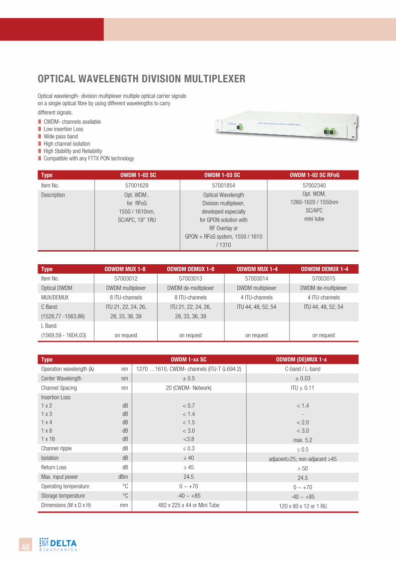
oPtical WaVelength diVision MUltiPleXeR Optical wavelength- division multiplexer multiple optical carrier signals on a single optical fibre by using different wavelengths to carry
different signals.
ll CWDM- channels available ll Low insertion Lossll Wide pass bandll High channel isolationll High Stability and Reliability ll Compatible with any FTTX PON technology
Item No.
Description
type oWdM 1-03 sc oWdM 1-02 sc Rfog
57001854
Optical Wavelength Division multiplexer, developed especially
for GPON solution with RF Overlay or
GPON + RFoG system, 1550 / 1610 / 1310
57001629
Opt. WDM , for RFoG
1550 / 1610nm, SC/APC, 19” 1RU
oWdM 1-02 sc
Item No.
Optical DWDM
MUX/DEMUX
C Band:
(1528,77 -1563,86)
L Band:
(1569,59 - 1604,03)
type odWdM deMUX 1-8 odWdM MUX 1-4
57003013
DWDM de-multiplexer
8 ITU-channels
ITU 21, 22, 24, 26,
28, 33, 36, 39
on request
57003014
DWDM multiplexer
4 ITU-channels
ITU 44, 48, 52, 54
on request
57003012
DWDM multiplexer
8 ITU-channels
ITU 21, 22, 24, 26,
28, 33, 36, 39
on request
odWdM MUX 1-8 odWdM deMUX 1-4
57003015
DWDM de-multiplexer
4 ITU-channels
ITU 44, 48, 52, 54
on request
Operation wavelength (λ) nm
Center Wavelength nm
Channel Spacing nm
Insertion Loss1 x 2 dB1 x 3 dB1 x 4 dB1 x 8 dB1 x 16 dB
Channel ripple dB
Isolation dB
Return Loss dB
Max. input power dBm
Operating temperature °C
Storage temperature °C
Dimensions (W x D x H) mm
type oWdM 1-xx sc
1270 …1610, CWDM- channels (ITU-T G.694.2)
± 0.5
20 (CWDM- Network)
< 0.7< 1.4< 1.5< 3.0<3.8
≤ 0.3
≥ 40
≥ 45
24.5
0 ~ +70
-40 ~ +85
482 x 225 x 44 or Mini Tube
odWdM (de)MUX 1-x
C-band / L-band
± 0.03
ITU ± 0.11
< 1,4-
< 2.0< 3.0
max. 5.2
≤ 0.5
adjacent≥25; non-adjacent ≥45
≥ 50
24.5
0 ~ +70
-40 ~ +85
120 x 80 x 12 or 1 RU
57002340Opt. WDM,
1260-1620 / 1550nmSC/APC
mini tube
49
OPti
cAl
SYSt
emS
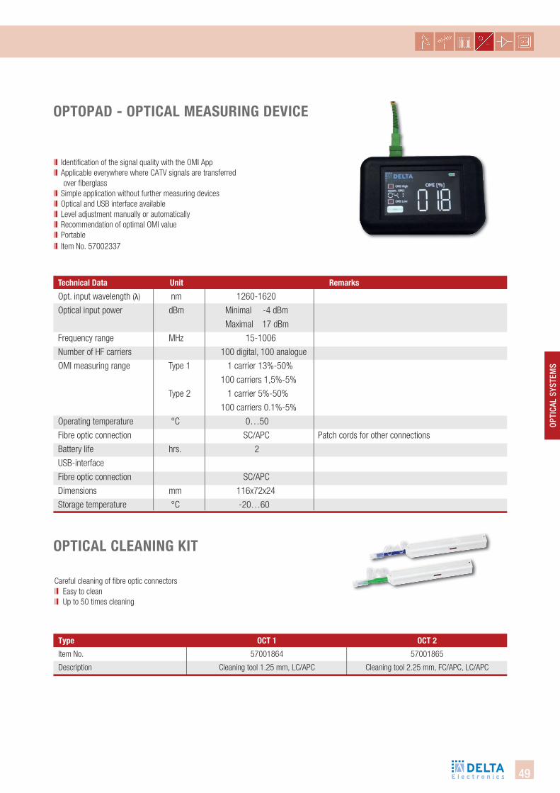
oPtoPad - oPtical MeasURing deVice
ll Identification of the signal quality with the OMI Appll Applicable everywhere where CATV signals are transferred over fiberglass ll Simple application without further measuring devicesll Optical and USB interface availablell Level adjustment manually or automatically ll Recommendation of optimal OMI valuell Portablell Item No. 57002337
technical data Unit Remarks
Opt. input wavelength (λ) nm 1260-1620
Optical input power dBm Minimal -4 dBm
Maximal 17 dBm
Frequency range MHz 15-1006
Number of HF carriers 100 digital, 100 analogue
OMI measuring range Type 1 1 carrier 13%-50%
100 carriers 1,5%-5%
Type 2 1 carrier 5%-50%
100 carriers 0.1%-5%
Operating temperature °C 0…50
Fibre optic connection SC/APC Patch cords for other connections
Battery life hrs. 2
USB-interface
Fibre optic connection SC/APC
Dimensions mm 116x72x24
Storage temperature °C -20…60
oPtical cleaning kit
Careful cleaning of fibre optic connectorsll Easy to cleanll Up to 50 times cleaning
Item No.
Description
type oct 1 oct 2
57001864
Cleaning tool 1.25 mm, LC/APC
57001865
Cleaning tool 2.25 mm, FC/APC, LC/APC
50
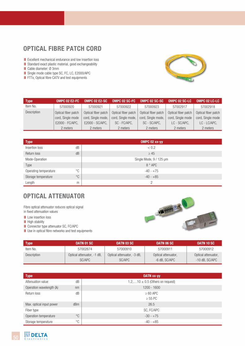
oPtical fibRe Patch coRd
ll Excellent mechanical endurance and low insertion loss ll Standard exact plastic material, good exchangeability ll Cable diameter: Ø 3mmll Single mode cable type SC, FC, LC, E2000/APCll FTTx, Optical fibre CATV and test equipments
Insertion loss dB
Return loss dB
Mode-Operation
Type
Operating temperature °C
Storage temperature °C
Length m
type oMPc 02 xx-yy
< 0.2
≥ 45
Single Mode, 9 / 125 µm
8 ° APC
-40 - +75
-40 - +85
2
oPtical attenUatoR
Fibre optical attenuator reduces optical signal in fixed attenuation values
ll Low insertion lossll High stability ll Connector type attenuator SC, FC/APCll Use in optical fibre networks and test equipments
Attenuation value dB
Operation wavelength (λ) nm
Return loss dB
Max. optical input power dBm
Fiber type
Operation temperature °C
Storage temperature °C
type oatn xx-yy
1.2,…10 ± 0.5 (Others on request)
1200 - 1600
≥ 60 APC≥ 55 PC
26.5
SC, FC/APC
-30 - +75
-40 - +85
57000923
Optical fiber patch cord, Single mode,
SC - SC/APC, 2 meters
Item No.
Description
57000922
Optical fiber patch cord, Single mode,
SC - FC/APC, 2 meters
57000921
Optical fiber patch cord, Single mode, E2000 - SC/APC,
2 meters
57000920
Optical fiber patch cord, Single modeE2000 - FC/APC,
2 meters
57002917
Optical fiber patch cord, Single mode
LC - SC/APC, 2 meters
57002918
Optical fiber patch cord, Single mode
LC - LC/APC, 2 meters
Item No.
Description
type oatn 01 sc oatn 03 sc oatn 06 sc oatn 10 sc
57000910
Optical attenuator, -3 dB, SC/APC
57000911
Optical attenuator, -6 dB, SC/APC
57000912
Optical attenuator, -10 dB, SC/APC
57002674
Optical attenuator, -1 dB, SC/APC
type oMPc 02 sc-fc oMPc 02 sc-scoMPc 02 e2-scoMPc 02 e2-fc oMPc 02 sc-lc oMPc 02 lc-lc
51
OPti
cAl
SYSt
emS
oPtical PoWeR MeteR
Fibre optical power meter for accurate measure of optical signal levels in FTTX deployments ll Hand held ll Auto power off ll Backlight LCD displayll Self calibrationll Power measurements in dBm or mw, insertion loss in dB
Item No.
Description
type oPM 200
57001862
Optical power meter, -50…+26 dBm
oPtical light soURce
Optical light source (transmitter) for simple screening offibre-optic networks
ll Fibre optical light source / transmitter for easy testing of optical network structures
ll Hand held ll Auto power off ll Backlight LCD display
Item No.
Description
type ols 103
57001863
Optical light source, 1310, 1550, 1610nm
Light power dBm
Transmitted wavelengths (λ) nm
Spectrum wide nm
Connector
Power supply
Operating Temperature °C
Dimensions mm
0…-5, adjustable
1310,1550,1610 (Other wavelengths on request)
< 5.5
FC (Interchangeable to SC, ST, 2.5 mm universal)
Battery 1.5 V AA (Operation app. 140 h)
-10 - +50
190 x 100 x 50
Measurement range dBm
Operation wavelength (λ) nm
Accuracy/Resolution
Connector
Power supply
Operating Temperature °C
Dimensions mm
-50…+26
800 - 1700 (850,1310,1490,1550,1590,1610 calibrated)
± 5% , 0.01
FC (Interchangeable to SC, ST, 2.5mm universal)
Battery 1.5 V AA (Operation app. 140h)
-10 - +60
190 x 100 x 50

52
notizen

A 81
A 81B 33
Radolfzell
Singen(Hohentwiel)
A 98
Stockach
B 34
B 313 B 31
Stockach Ost
E 54 Kreuz HegauBodman
A 81
A 81B 33
Radolfzell
SingenSingen(Hohentwiel)
A 98
StockachStockachStockachStockachStockachStockach
B 34
B 313 B 31
Stockach Ost
E 54 Kreuz HegauBodmanBodmanBodman
Radolfzell
Bodman
Bodensee
A 81
A 81B 33
Radolfzell
Singen(Hohentwiel)
A 98
Stockach
B 34
B 313 B 31
Stockach Ost
E 54 Kreuz Hegau
germanyDCT DELTA GmbH
Bodanrückstraße 1
D-78351 Bodman
Tel. +49 7773 929258
Fax +49 7773 929259
www.dct-delta.de
SwitzerlandDELTA Swiss AG
Industriezone Schächenwald
CH-6460 Altdorf
Tel. +41 4161 91400
Fax +41 4161 91409
www.delta-swiss.ch Art.
7000
0180
Ed. 6
.16