Embed Size (px)
Citation preview
Int J Fract (2015) 194:37–44DOI 10.1007/s10704-015-0036-z
ORIGINAL PAPER
A simplified hardening cohesive zone model for bondlinethickness dependence on adhesive joints
Yongtao Sun · Nicola Pugno · Baoming Gong ·Qian Ding
Received: 2 March 2015 / Accepted: 17 July 2015 / Published online: 25 July 2015© Springer Science+Business Media Dordrecht 2015
Abstract In this paper, a tri-material adhesive systemwith nonlinear cohesive springs embedded betweentwo elasto-plastic adhesive layers is proposed to predictthe adhesive thickness effects on the fracture energy ofbonded joints. The localized plastic and damage behav-iours along the interface are described by the hardeningcohesive zone models. The thickness dependent inter-facial energy release rate is divided into the essentialseparation energy rate and the energy dissipation rateof the plasticization. The adhesive thickness dependenthardening cohesive zone model is implemented intothe proposed numerical method to predict the failureof the adhesive joints. The validation of the model isperformed by comparison with the experimental data.
Y. Sun · Q. DingDepartment of Mechanical Engineering, TianjinUniversity, Tianjin 300072, China
N. PugnoLaboratory of Bio-Inspired & Graphene Nanomechanics,Department of Civil, Environmental and MechanicalEngineering, Università di Trento, 38123 Trento, Italy
N. PugnoCenter for Materials and Microsystems, Fondazione BrunoKessler, 38123 Povo (Trento), Italy
N. PugnoSchool of Engineering and Materials Science, Queen MaryUniversity of London, London E1 4NS, UK
B. Gong (B)Department of Materials Science and Engineering, TianjinUniversity, Tianjin 300072, Chinae-mail: [email protected]
Keywords Cohesive zone model · Adhesive joints ·Bondline thickness · Fracture
1 Introduction
Adhesive joints are being widely used in industries,e.g., in the automotive and aerospace industries. Somespecimens have been used to examine the fracture prop-erties of adhesive joints, including double cantileverbeam (DCB) (Mall and Ramamurthy 1989; Abou-Hamda et al. 1998; Chai 1988, 1986; Bascom et al.1975; Kinloch and Shaw 1981; Hunston et al. 1989),compact tension (CT) (Daghiyani et al. 1995), peel tests(Kawashita et al. 2008; Pardoen et al. 2005). Throughthese tests, a significant fracture strength and tough-ness improvement by increasing adhesive thickness hasbeen widely observed (Abou-Hamda et al. 1998; Chai1986; Bascom et al. 1975; Kinloch and Shaw 1981;Daghiyani et al. 1995; Kawashita et al. 2008; Pardoenet al. 2005). Therefore, from the point view of design,an interpretation of bondline thickness effects on thefracture behaviour of adhesive joints is instructive tooptimize the global properties. Linear Elastic Frac-ture Mechanics (LEFM) and the interfacial fracturemechanics are introduced to predict the failure of theadhesive joint, and the Cohesive Zone Model (CZM)proposed by Barenblatt (1959), Barenblatt (1962) andDugdale (1960) was proven to be versatile to studycrack propagation in interface problems. To solve dif-ferent fracture problems, several shapes of the CZM
123

38 Y. Sun et al.
are proposed, namely the linear softening shape (Baren-blatt 1962;Dugdale 1960), the trapezoidal shape (Bilbyet al. 1963), as well as the bell-shapes or exponentialforms (Willis 1967;Wnuk1974;Hillerborg et al. 1976).In spite of this remarkable development of the nonlin-ear fracture mechanics models, the shape of the CZMand its input parameters are often obtained by fitting theexperimental data or by inverse analysis (Burke et al.2007;Valoroso and Fedele 2010;Gain et al. 2011; Shenand Paulino 2011; Chen et al. 2014). Moreover, thecohesive law is considered as the equivalent interfacialtraction-separation to describe the interaction acrossthe adherents, and many experiments have indicatedthat the cohesive law may be thickness dependent dueto the plastic zone size and deformation magnitude inthe adhesive material (Azari et al. 2011). As a result,the cohesive laws for different geometric joints haveto be calibrated through different experiment data, andthe transferability of the CZM parameters is seriouslylimited. The aim of this paper is thus to apply the sim-plified hardening cohesive zone model to estimate theadhesive thickness dependent effect on the fracture ofthe bonded joints, where the cohesive parameters areobtained explicitly from the tensile properties of theadhesive.
2 The hardening cohesive law
2.1 Basic concepts of the cohesive zone model
The basic assumption of the cohesive zone model isthe formation, as an extension of the real crack, of afictitious crack, referred to as the process zone, wherethe material, albeit damaged, is still able to transferstresses. In the process zone, the stresses transferred bythe material are functions of the displacement disconti-nuity, according to a proper cohesive law, whilst in theuncracked zone the behaviour of the material is linear-elastic or elasto-plastic. Some cohesive crack modelsmay share the common character that the cohesive trac-tion at thefictitious tip is zero.However, fromaphysicalpoint of view, the cohesive law describes the progres-sive fracture process induced by finite deformation orapplied stress. It is thus reasonable that the initial valueof the traction versus separation law should be differentfrom zero (Carpinteri et al. 2012). Mathematically, thecohesive lawwith an initial zero traction does not guar-antee the absence of stress singularity at the fictitious
crack tip (Jin and Sun 2005). Moreover, the cohesivelaw of the adhesive joints is usually thickness depen-dent on the process zone size and the localized plasticdeformation magnitude (Azari et al. 2011). In partic-ular, the volumetric plastic energy dissipation rate isthickness dependent. Therefore, it is reasonable to pos-tulate that the equivalent interfacial energy release ratecomprises the energy dissipation referred to the plasti-cization of the material surrounding the process zoneand the separation energy rate required to create newfracture surfaces.
2.2 Derivation of the hardening cohesive law
It is assumed in the present work that the localized plas-tic and damage behaviour of the adhesive joints aredescribed by hardening cohesive zone model wherelocalized plastic dissipation and crack formation andpropagation take placeCarpinteri et al. (2012). Accord-ingly, the mechanical behaviour of the adhesive jointsunder uniaxial tension can be divided into the followingstages:
(a) Homogeneous elastic deformation in adhesivebulk: the materials behave linear elastically with-out any damage or localized zone (see Fig. 1a). Theconstitutive law is that shown in Fig. 1a, and theelongation δ is
δ = εL = σ L
Eadhesive, for σ ≤ σy. (1)
(b) Localized plastic deformation in the adhesivelayer: after the elastic limit of the adhesive mate-rial, the deformation starts to localize and giverise to the localized plasticity within a limitedportion of the adhesive (Fig. 1b). In the presentwork a simplified linear hardening plasticity isassumed. Thus, the linear hardening cohesivetraction-elongation relationship is given by
δ = σ − σy
k1, for σ f > σ > σy . (2)
(c) Crack formation of the adhesive: as the localizedplastic deformation proceeds, microvoid enlarge-ment and coalescence in the polymer leads to thesoftening behaviour, and the branch is provided as
σ = (δ f − δ
)k2, for δc < δ ≤ δ f . (3)
123
A simplified hardening cohesive zone model 39
Fig. 1 The simplified hardening cohesive law and the tri-material adhesive system for the adhesive joints
where k1 and k2 are two cohesive shape parametersobtained by the best-fitting experimental data, whilethe shape determined by k1 and k2 has only a slightinfluence on mechanical behavior as claimed by Tver-gaard and Hutchinson (1992).
3 The equivalent thickness dependence behaviourof the adhesive joints
In this paper, it is assumed that a tri-material adhe-sive system equivalently composes of the virtual spring
embedded between two adhesive layers with modulusEadhesvie and the half thickness H/2 (see Fig. 1d). Theadhesive layers refer to the diffuse plasticization of thematerial surrounding the process zone, and the local-ized deformation and separation to create new fracturesurfaces are represented by the nonlinear springs. Thespring is constituted according to the hardening cohe-sive law, and its volume is assumed to be zero for theweak interface, and a linear hardening plasticity for theadhesive layer. The bi-material interface between adhe-sive and spring is perfectly bonded. The separation ofthe adhesive system under loading is the sum of the
deformation of the adhesive and the nonlinear spring.For adhesive of the DBC specimen, it is assumed thatthe adhesive and the cohesive zone act as springs inseries (Kanninen 1973; Penado 2006; Williams andHadavinia 2002). Paggi and Wriggers (2011) recentlycaptured the finite thickness interface properties in thenonlocal cohesive zone model using the similar strat-egy. In this case, the total displacement of the system isthe sum of the individual contributions. The relation-ship between the traction σ and the cohesive opening δ
of the adhesive can be distinguished into three differentstages:
⎧⎪⎪⎪⎪⎪⎨
⎪⎪⎪⎪⎪⎩
Homogeneous elastic deformation : σ = Eadhesiveε for 0 < ε ≤ εy
Hardening phase : σ =(�+ σy
k1
)
(H
2Eadhesive+ 1
k1
) + σy
H2Eadhesive(
H2Eadhesive
+ 1k1
) for 0 < δ ≤ δc
Softening phase : � =(
σ2Eadhesive
H)
+(δ f − σ
k2
)for δ > δc
. (4)
where σy and σf is the yielding strength and tensilestrength of the bulk adhesive, respectively. The equiva-lent fracture energy in the adhesive can be determinedas
GIc = ∫δc0 σ (δ) dδ + ∫δ f
δcσ (δ) dδ, δy = σy H
Eadhesive.
(5)
Substituting Eq. (4) into Eq. (5), we can obtain
123
40 Y. Sun et al.
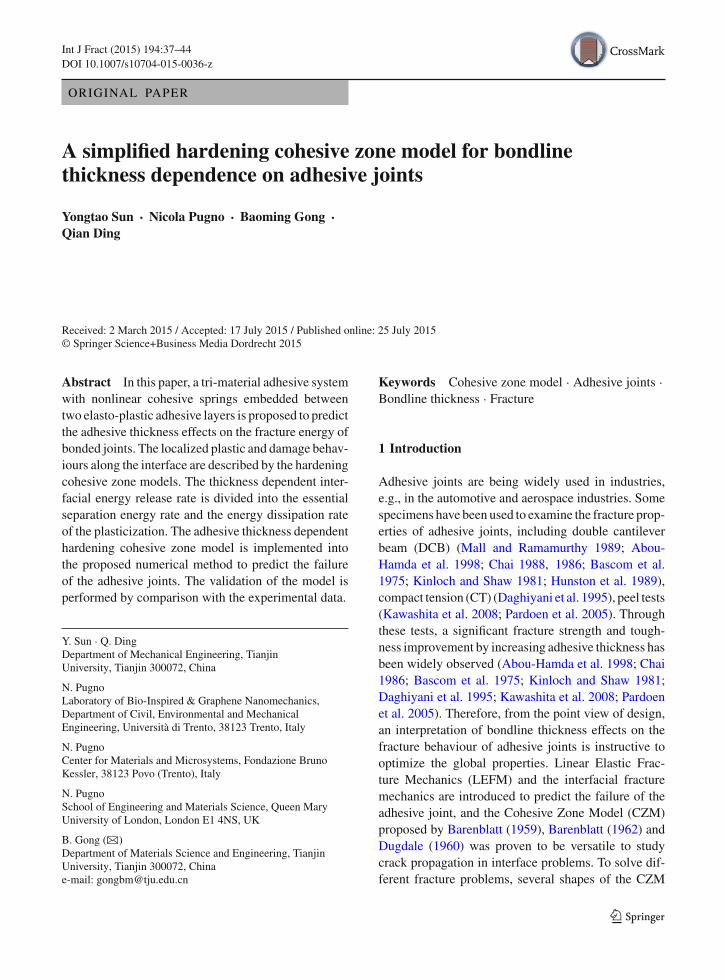
Fig. 2 The two-node,zero-thickness interfaceelements and the numericalimplementation
Node 2
Node 1 Node 1
Node 2
U4
U1
U2
U3
F4
F1
F2
F3
x
y
Interface elements
GIc
={(
σ f + σy
2
)[σ f
(H
2Eadhesive+ 1
k1
)− H
2Eadhesiveσy
]
−(
σ f + σy
2
)σy
k1
}+ 1
2σ 2f
(H
2Eadhesive− 1
k2
). (6)
Considering the energy dissipation in both volume andthe hardening cohesive zone, Eq. (6) can be alterna-tively rewritten as
GIc = GH + Gcohesive. (7)
where GH is the volumetric plastic energy dissipationrate and is thickness dependent, Gcohesive is the gener-alized Griffith energy. Comparing Eq. (7) with Eq. (6),
the following expressions can be directly obtained
GH =(
H
2Eadhesive
)(2σ 2
f − σ 2y
). (8a)
Gcohesive = σ 2f − σ 2
y
2k1− σ 2
f
2k2= constant. (8b)
It is obvious in Eq. (7) that the nominal fracture energyis approximately proportional to the adhesive thick-ness, and Gcohesive can be determined from the frac-ture toughness corresponding to a reference bond-line thickness. Taking constraint effects into consider-ation, Yan et al. (2001) obtained the similar result thatG = CmσfH(Cm is a constraint constant depending onthe ultimate stress). Once Gcohesive is obtained by the
123
A simplified hardening cohesive zone model 41
experimental fitting, k1 and k2 are dummy parameterswhich are not necessarily known.
4 Numerical implementation and experimentalvalidation
The commercial code ABAQUS/Standard is used forthe debonding simulations. The weak interface is rep-resented by 2-node, zero-thickness interface elementsin a user-defined subroutine (UEL). On the basis of theequivalent constitutive laws previously introduced forjoints, the fracturing along the interface between twoadherents can be described by means of the discretenodal release approach proposed byCarpinteri et al. forreinforced concrete beams (Yan et al. 2001) and duc-tile fracture (Carpinteri et al. 2012). In this scheme, thehardening cohesive zone model is applied in conjunc-tion with nonlinear spring type elements. The cohesivelaw is implemented as the spring force vs. displacementseparation according to the constitutive laws in Eq. (4).
Since the element has two nodes and each nodehas two degree of freedom for the two-dimensionalanalysis, the current nodal displacement vector withinABAQUS user subroutine UEL is {U1,U2,U3,U4}.The displacement components for node 1 are U1 andU2in the x and y directions, respectively. Similarly, U3
and U4 are the displacement components for node 2as shown in Fig 2. Considering the linear hardeningand softening branches in the traction-separation law,the nodal forces {F1, F2, F3, F4} can be obtained asfollows
⎧⎪⎪⎨
⎪⎪⎩
F1F2F3F4
⎫⎪⎪⎬
⎪⎪⎭= KU =
⎡
⎢⎢⎣
kix 0 −kix 00 kiy 0 −kiy
−kix 0 kix 00 −kiy 0 kiy
⎤
⎥⎥⎦
⎧⎪⎪⎨
⎪⎪⎩
U1
U2
U3
U4
⎫⎪⎪⎬
⎪⎪⎭;
(9)
where kix and kiy are values of the cohesive stiffnesscorresponding to different branches in the traction-separation lawCarpinteri et al. (2012);K is the stiffnessmatrix assigned to the AMATRX in the UEL subrou-tine; U is the nodal displacement vector. It is worthnoting that the same numerical algorithm can be prof-itably used with the nonlinear cohesive law through themulti-segment method where the nonlinear traction-separation law is approximated by multiple linear rela-tions. The beams are discretizedwith standard full inte-
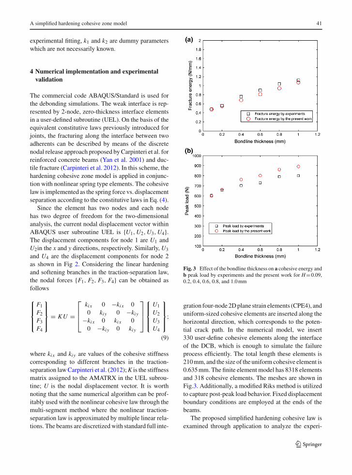
Fig. 3 Effect of the bondline thickness on a cohesive energy andb peak load by experiments and the present work for H=0.09,0.2, 0.4, 0.6, 0.8, and 1.0mm
gration four-node2Dplane strain elements (CPE4), anduniform-sized cohesive elements are inserted along thehorizontal direction, which corresponds to the poten-tial crack path. In the numerical model, we insert330 user-define cohesive elements along the interfaceof the DCB, which is enough to simulate the failureprocess efficiently. The total length these elements is210mm, and the size of the uniform cohesive element is0.635mm. The finite element model has 8318 elementsand 318 cohesive elements. The meshes are shown inFig.3. Additionally, a modified Riks method is utilizedto capture post-peak load behavior. Fixed displacementboundary conditions are employed at the ends of thebeams.
The proposed simplified hardening cohesive law isexamined through application to analyze the experi-
123
42 Y. Sun et al.
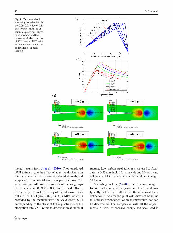
Fig. 4 The normalizedhardening cohesive law forh=0.09, 0.2, 0.4, 0.6, 0.8,and 1.0mm (a); the loadversus displacement curveby experiment and thepresent work (b); contoursof S22 stress of DCB withdifferent adhesive thicknessunder Mode I at peakloading (c)
mental results from Ji et al. (2010). They employedDCB to investigate the effect of adhesive thickness oninterfacial energy release rate, interfacial strength, andshapes of the interfacial traction-separation laws. Theactual average adhesive thicknesses of the six groupsof specimens are 0.09, 0.2, 0.4, 0.6, 0.8, and 1.0mm,respectively. Ultimate stress σf of the adhesive mate-rial (LOCTITE Hysol 9460) is 30.3 MPa which isprovided by the manufacturer; the yield stress σy iscorresponding to the stress at 0.2% plastic strain; theelongation rate 3.5% refers to deformation at the final
rupture. Low carbon steel adherents are used to fabri-cate the 6.35mm thick, 25.4mmwide and 254mm longadherends of DCB specimens with initial crack length52.2mm.
According to Eqs. (6)–(8b), the fracture energiesfor six thickness adhesive joints are determined ana-lytically in Fig. 3a. Furthermore, the numerical load-deflection curves for the joint with different bondlinethicknesses are obtained, where the maximum load canbe determined. The comparison with all the experi-ments in terms of cohesive energy and peak load is
123
A simplified hardening cohesive zone model 43
shown in Fig. 3a, b,where a very good approximation isplotted for all the considered bondline thicknesses. Asan example, the load-deflection curve for the joint witha 0.2mm thick adhesive layer predicted by the hard-ening cohesive law is plotted against the experimentin Fig. 4b for comparison. In addition, the normalizedcohesive law, the others load-deflection responses andthe distribution of S22 stress at peak loading for h=0.2,0.4, 0.6, 0.8mm are also plotted in Fig. 4a–c, respec-tively.
5 Discussion
In this paper, a simplified hardening cohesive law isproposed to predict the adhesive thickness effect onthe fracture behaviours of bonded joints. Accordingly,the thickness dependent interfacial energy release rateis comprised of the separation energy rate and the plas-tic energy dissipation rate. More specifically, the hard-ening cohesive energy can be divided into GH, thevolumetric plastic energy dissipation rate and thick-ness dependent, and Gcohesive, the generalized Griffithenergy. As a result, the present analyses indicate thatthe nominal fracture energy is approximately propor-tional to the adhesive thickness, which is in consis-tent with the suggestion by Yan et al. (2001). Takingconstraint effects into consideration, they obtained thesimilar result (Yan et al. 2001).
Regarding to the relationship between the horizon-tal displacement and the applied shear traction, thesliding behaviour can be identified through the sametri-material system. For the mixed mode, we can usethe dimensionless separation parameter to couple theopening and sliding modes (Tvergaard and Hutchinson1992; Paggi andWriggers 2011). On the other hand, weassume a constant cohesive strength for approximationso that in the hardening cohesive law for a thin layer, thefailure is prone to strength-controlled since the hard-ening branch becomes steeper; for a thick layer, thehardening branch is descended more gentally, whichis deformation-controlled failure (see Fig. 4a). In gen-eral, the critical cohesive parameters are considered todepend on the stress-state (Yan et al. 2001; Siegmundand Brocks 2000). Experimental results indicate dif-ferent tendencies that fracture energy increases (Chai2004) or decreases (Bascom et al. 1975; Chai 1986) orincreases followed by decreasing (Kinloch and Shaw1981) as the bond thickness is increased. For the case,
fracture ismainly controlled by a critical opening stressdependent on the stress tri-axiality or constraint para-meters. As the thickness increases, critical crack tipopening displacement is a more suitable fracture crite-rion, and the fracture toughenss of the joint asymptot-ically approaches the bulk value. In fact, the apparentsize effect on fracture energy and strength of adhesivejoint is actually determined by interactions betweenprocess zone and boundary conditions, or the distancebetween the crack-tip to the boundary of the structure.From the micromechanical point of view, two compet-ing fracture mechanisms can be assumed for a con-strained adhesive layer in rigid adherends. In a verythin adhesive layer, cavitation ahead of the crack tipmay precede plastic flow, and the fracture is dominatedby high triaxial stresses; otherwise, crack tip bluntingmay result in void-crack coalescence in a thick adhe-sive layer. Thus, the models for thin and thick adhe-sive should be considered separately to determine thecomprehensive adhesive-thickness dependent fracturebehaviours as suggested in Duan et al. (2004).
Acknowledgments B.M.G. gratefully acknowledges the re-search support provided byNational Natural Science Foundationof China (NSFC) (Grant No. 51305295) and Doctoral Fund ofMinistry of Education of China (Grant No. 20130032120006).N.M.P. is supported by theEuropeanResearchCouncil (ERCStGIdeas 2011 BIHSNAMNo. 279985 on ‘Bio-inspired hierarchicalsupernanomaterials’, ERC PoC 2013-1 REPLICA2 No. 619448on ‘Large-area replication of biological anti-adhesive nanosur-faces’, ERC PoC 2013-2 KNOTOUGH No. 632277 on ‘Super-tough knotted fibres’), by the European Commission under theGraphene Flagship (WP10 ‘Nanocomposites’, No. 604391) andby the Autonomous Province of Trento (Graphene PAT WP10,code 81017).
References
Abou-Hamda MM, Megahed MM, Hammouda MMI (1998)Fatigue crack growth in double cantilever beam specimenwith an adhesive layer. Eng Fract Mech 60:605–614
Azari S, Papini M, Spelt JK (2011) Effect of adhesive thick-ness on fatigue and fracture of toughened epoxy joints–PartII: analysis and finite element modeling. Eng Fract Mech78:138–152
Barenblatt GI (1959) The formation of equilibrium cracks duringbrittle fracture: general ideas and hypotheses. J Appl MathMech 23:622–636
Barenblatt GI (1962) The mathematical theory of equilibriumcracks in brittle fracture. Adv Appl Mech 7:55–129
Bascom WD, Cottington RL, Jones RL, Peyser P (1975) Thefracture of epoxy and elastomer-modified epoxy polymersin bulk and as adhesives. J Appl Polym Sci 19:2545–2562
123
44 Y. Sun et al.
BilbyBA,Cottrell AH, SwindenKH (1963) The spread of plasticyield from a notch. Proc R Soc Lond A 272:304–314
BurkeBCP,KimSO,KimKS (2007) Partial polar decompositioninverse method applied to determination of internal stressesin an elastic complex structure. Int J Solids Struct 44:2010–2020
CarpinteriA,CorradoM,PaggiM,ManciniG (2009)Newmodelfor the analysis of size-scale effects on the ductility of rein-forced concrete elements in bending. J Eng Mech (ASCE)135:221–229
Carpinteri A, Gong B, Corrado M (2012) Hardening cohe-sive/overlapping zonemodel formetallicmaterials: the size-scale independent constitutive law. Eng Fract Mech 82:29–45
Chai H (1986) Bond thickness effect in adhesive joints and itssignificance for mode I interlaminar fracture of compos-ites. Composite materials testing and design, ASTM STP893:209–231
Chai H (1988) Fracture work of thin bondline adhesive joints. JMater Sci Lett 7:399–401
Chai H (2004) The effects of bond thickness, rate and tempera-ture on the deformation and fracture of structural adhesivesunder shear loading. Int J Fract 130:497–515
Chen X, Deng X, Sutton MA, Zavattieri P (2014) An inverseanalysis of cohesive zonemodel parameter values for ductilecrack growth simulations. Int J Mech Sci 79:206–215
Daghiyani HR, Ye L, Mai Y-W (1995) Mode-I fracture behav-iour of adhesive joints part I. relationship between fractureenergy and bond thickness. J Adhes 53:149–162
Duan Kai, Xiaozhi Hu, Mai Yiu-Wing (2004) Substrate con-straint and adhesive thickness effects on fracture toughnessof adhesive joints. J Adhes Sci Technol 18:39–53
Dugdale DS (1960) Yielding of steel sheets containing slits. JMech Phys Solids 8:100–104
Gain AL, Carroll J, Paulino GH, Lambros J (2011) A hybridexperimental/numerical technique to extract cohesive frac-ture properties formode-I fracture of quasi-brittlematerials.Int J Fract 169:113–131
Hillerborg A, Modeer M, Petersson PE (1976) Analysis of crackformation and crack growth in concrete bymeans of fracturemechanics and finite elements. Cem Concr Res 6:773–782
Hunston DL, Kinloch AJ, Wang SS (1989) Micromechanics offracture in structural adhesive bonds. J Adhes 28:103–114
JiG,OuyangZ,LiG, IbekweS, PangS (2010)Effects of adhesivethickness on global and local Mode-I interfacial fracture ofbonded joints. Int J Solids Struct 47:2445–2448
Jin Z-H, Sun CT (2005) Cohesive fracture model based on neck-ing. Int J Fract 134:91–108
Kanninen MF (1973) An augmented double cantilever beammodel for studying crack propagated and arrest. Int J Fract9:83–92
Kawashita LF, Kinloch AJ, Moore DR, Williams JG (2008) Theinfluence of bond line thickness and peel arm thickness onadhesive fracture toughness of rubber toughened epoxy-aluminium alloy laminates. Int J Adhes Adhes 28:199–210
Kinloch AJ, Shaw SJ (1981) The fracture resistance of a tough-ened epoxy adhesive. J Adhes 12:59–77
Mall S, Ramamurthy G (1989) Effect of bond thickness on frac-ture and fatigue strength of adhesively bonded compositejoints. Int J Adhes 9:33–37
Paggi M,Wriggers P (2011) A nonlocal cohesive zone model forfinite thickness interfaces-Part I: mathematical formulationand validation with molecular dynamics. ComputMater Sci50(5):1625–1633
Pardoen T, Ferracin T, Landis CM, Delannay F (2005) Con-straint effects in adhesive joint fracture. J Mech Phys Solids53:1951–1983
Penado FE (2006) A closed form solution for the energy releaserate of the double cantilever beam specimen with an adhe-sive layer. J Compos Mater 40(8):701–715
ShenB, PaulinoGH (2011)Direct extraction of cohesive fractureproperties from digital image correlation: a hybrid inversetechnique. Exp Mech 51:143–163
Siegmund T, Brocks W (2000) A numerical study on the corre-lation between the work of separation and the dissipationrate in ductile fracture. Eng Fract Mech 67:139–154
Tvergaard V, Hutchinson JW (1992) The relation between crackgrowth resistance and fracture process parameters in elastic-plastic solids. J Mech Phys Solids 40:1377–1397
Valoroso N, Fedele R (2010) Characterization of a cohesive-zone model describing damage and de-cohesion at bondedinterfaces. Sensitivity analysis and mode-I parameter iden-tification. Int J Solids Struct 47:1666–1677
Williams J, HadaviniaH (2002)Analytical solutions for cohesivezone models. J Mech Phys Solids 50:809–825
Willis JR (1967) A comparison of the fracture criteria of Griffithand Barenblatt. J Mech Phys Solids 15:151–162
Wnuk MP (1974) Quasistatic extension of a tensile crack con-tained inviscoelastic-plastic solid. JApplMech41:234–242
Yan C, Mai Y-W, Lin Y (2001) Effect of bond thickness on frac-ture behaviour in adhesive joints. J Adhes 75(1):27–44
123