Embed Size (px)
Citation preview

June 2009
Bondline Analysis and Bonded RepairsCACRC Meeting / Workshop for Composite DT & Maintenance,
Tokyo, June 1-5, 2009
CACRC Meeting / Workshop for Composite DT & Maintenance
Presented by
Stephane MahdiStructure Analysis,Methods and Technologies

June 2009Bondline Analysis and Bonded Repairs Page 2©A
IRB
US
S.A
.S.
All
rights
rese
rved.
Confidential and p
roprieta
rydocum
ent.
Content
I. Introduction
II. Composites Bonded Joints/Interfaces Analysis
III. Composites Bonded Repairs Analysis
IV. Perspectives and Conclusions

June 2009Bondline Analysis and Bonded Repairs Page 3©A
IRB
US
S.A
.S.
All
rights
rese
rved.
Confidential and p
roprieta
rydocum
ent.
I. Introduction

June 2009Bondline Analysis and Bonded Repairs Page 4©A
IRB
US
S.A
.S.
All
rights
rese
rved.
Confidential and p
roprieta
rydocum
ent.
Bonded Assembly / Interfaces
CO-BONDING: Components bonded together
during cure of one of the components
•Comp. 1 cured•Comp. 2 un-cured
•Adhesive
CO-CURING: Components cured together• Component 1 un-cured
• Component 2 un-cured
SECONDARY BONDING: Components
bonded together with separate bonding
operation
•Component 1 cured•Component 2 cured•Adhesive
1
2
1
2Adhesive
1
2Adhesive•Comp. 2 cured
•Comp. 1 un-cured•Adhesive

June 2009Bondline Analysis and Bonded Repairs Page 5©A
IRB
US
S.A
.S.
All
rights
rese
rved.
Confidential and p
roprieta
rydocum
ent.
Specificities
• The properties of interface and bonds are difficult to determine.
• Achilles' heel of bonds:
� Weak in carrying peel and tension loads,
� There are no generally agreed failure criteria relevant to all loci of failure.
�Fatigue sensitive items and governed primarily by durability rather than the mere
ultimate static strength substantiation,
�The locus of failure in aged conditions is more important that the determination
of the mere ultimate capability of the joint.
• How to handle singularities in calculations (Where are they ?):
�Local geometry and plasticity/damage are likely to redistribute singular fields,
�There is a need to simplify and improve the accuracy of calculation methods.

June 2009Bondline Analysis and Bonded Repairs Page 6©A
IRB
US
S.A
.S.
All
rights
rese
rved.
Confidential and p
roprieta
rydocum
ent.
Industrialisation Aspects
• Quality Control of the materials and the process ensures good bonding:
�Compatibility tests in order to address sensitivity to durability parameters,
�Controlled surface preparation and Controlled Process, until Bonding is
completed, is key (Effect of pre-bond moisture, time between surface
preparation and bonding, etc.),
�Control of bond thickness [Strength and Toughness are independently linked with the adhesive thickness],
�Assessment of F&DT performance and taking into account effect of defects
(porosity in bond line, imperfect bonding, etc.) is necessary.
• Kissing bonds. FAR/CS 25.601 prevents the use of questionable design features and precautions in FAR/CS 23.573 applies (now in AC20-107B).Bonded Joints:
�shall not be used in structural single-load path application,
�shall not be the weak link fuse by material and design choices,
�shall sustain Limit Load, assuming no bond between two crack arresting features, and taking into account the repeated application of the loads.

June 2009Bondline Analysis and Bonded Repairs Page 7©A
IRB
US
S.A
.S.
All
rights
rese
rved.
Confidential and p
roprieta
rydocum
ent.
Structure Analysis Stress Process 1,2
Several Design/Calculation loops taking into account all load configurations.
Databank: Interface loads,
2D flows, Beam forces,
Rod forces, Grid point
forces
Refined GFEM,
Refined DFEM
FE, Analytical
studies,
Deformation and
Failure Criteria
Geo. data
Sizes
Thicknesses
Lay-ups
Fasteners
…
RF status
Analysis and
refined FEM
solutions
Geometrical
update
Optimisation Iteration
Component
loads
GFEM : Generation of internal loads
A Stress Process is required defining different level of analyses, e.g:�Pre-sizing: fast evaluation (max. simplifications, gross accuracy),
�Quick Sizing with accuracy in line with simplifications,
�Advanced Sizing for state-of the-art calculations.
1, Integrating Materials Modeling Aspects into the Industrial An1, Integrating Materials Modeling Aspects into the Industrial Analysis of Composite Structuresalysis of Composite Structures, ,
Stephane Mahdi, Stephane Mahdi, CompTestCompTest 2008, Dayton, 222008, Dayton, 22--24 Oct. 200824 Oct. 2008
2,2, Application of multiApplication of multi--scale analyses to the sizing of composites structures and bondedscale analyses to the sizing of composites structures and bonded assembliesassemblies, ,
Stephane Mahdi, Composites2009, London, 1Stephane Mahdi, Composites2009, London, 1--3 Apr. 20093 Apr. 2009

June 2009Bondline Analysis and Bonded Repairs Page 8©A
IRB
US
S.A
.S.
All
rights
rese
rved.
Confidential and p
roprieta
rydocum
ent.
Structure Strength Analyses
� Structure Strength Analysis is, typically, a three steps process:
�Internal load calculation from GFEM,
�Internal stress calculations from 2D or specific 3D analyses,
�Optimisation and Calculations of Margins of safety.
Example for Bonded Joint / Interface analysisExample for Bonded Joint / Interface analysis
1. Retrieval of panel loads, from GFEM to DFEM,
2. Calculation of Stresses along the Bondline (analytical / FE)
3. Failure assessment, with allowable defined with a Building Block Approach
� Dependence on testing for the generation of adequate ‘fitting parameters’,
� Limitation of the structural design space,
GFEM
Global Analysis
y
z
Local Analysis
MARGINS MARGINS OF OF
SAFETYSAFETYDFEM
LOADSLOADS
BCsBCs
ENV.ENV.
Etc.Etc.

June 2009Bondline Analysis and Bonded Repairs Page 9©A
IRB
US
S.A
.S.
All
rights
rese
rved.
Confidential and p
roprieta
rydocum
ent.
II. Composites Bonded Joints / Interfaces Analysis
x
z
y
3
2 4
12
5
6
7 108
119
1
June 2009Bondline Analysis and Bonded Repairs Page 10©A
IRB
US
S.A
.S.
All
rights
rese
rved.
Confidential and p
roprieta
rydocum
ent.
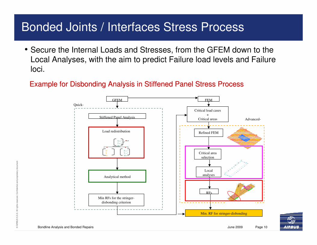
Bonded Joints / Interfaces Stress Process
• Secure the Internal Loads and Stresses, from the GFEM down to the Local Analyses, with the aim to predict Failure load levels and Failure loci.
Critical load cases
+
Critical areas
GFEM
Refined FEMLoad redistribution
Critical area
selection
Min RFs for the stringer-
disbonding criterion
Min. RF for stringer-disbonding
N
T
M
N = ?
T = ?
M = ?
N = ?
T = ?
M = ?
z
RFs
Local
analysesAnalytical method
Stiffened Panel Analysis
FEM
Quick-
Advanced-
Example for Example for DisbondingDisbonding Analysis in Stiffened Panel Stress ProcessAnalysis in Stiffened Panel Stress Process

June 2009Bondline Analysis and Bonded Repairs Page 11©A
IRB
US
S.A
.S.
All
rights
rese
rved.
Confidential and p
roprieta
rydocum
ent.
Global-Local Analyses / Securing Internal Stresses
Global Model (refined) Local model
Nx
W
Nx
Nxy
Nxy
Global / Local Bondline Analysis
Overlap Length
Shear Stress Reference Analysis
Local Analysis
Similar Results
Reference Model
Nx (local)
+
Nxy (local)

June 2009Bondline Analysis and Bonded Repairs Page 12©A
IRB
US
S.A
.S.
All
rights
rese
rved.
Confidential and p
roprieta
rydocum
ent.
Local Analyses for Strength
FE Stress approachAnalytical Stress approach
Analytical Fracture mechanics /
Damage Mechanics
FE Fracture mechanics /
Damage Mechanics
QUICK- ADVANCED-

June 2009Bondline Analysis and Bonded Repairs Page 13©A
IRB
US
S.A
.S.
All
rights
rese
rved.
Confidential and p
roprieta
rydocum
ent.
Strength of Materials Approach
• Calculation of Shear / Peel Stresses from analytical or parametric-FE models
�Linear / NL bond properties.
�Simplified or Detailed Geometry,
− Peak Stress/Strain varies with the (local) design,
+ Good agreement between analytical and numerical calculations. Good Predictive Capability.
0 2 4 6 8 10 12
Overlap
Peel stress
Analytical EF
• Measurement of Constitutive Properties
�Shear Stress-Strain (ASTMD5656),
�Peel Stress-Strain(Measured / Estimated),
�Definition of Interactive Failure Criteria (mostly empirical),
�Derivation of Design Values.
[e.g. [e.g. Recent Advanced in Structural joints and Repairs Recent Advanced in Structural joints and Repairs for composite materialsfor composite materials, Hart, Hart--Smith, Proceedings of Smith, Proceedings of SAMPE, Seattle, 2003]SAMPE, Seattle, 2003]

June 2009Bondline Analysis and Bonded Repairs Page 14©A
IRB
US
S.A
.S.
All
rights
rese
rved.
Confidential and p
roprieta
rydocum
ent.
Fracture / Damage Mechanics Approach
• Analytical / Numerical Calculations of SERR
�Typically linear interface properties,
�Simplified or Detailed Geometry
− Numerical Stability is difficult to ensure
� Advanced User.
+ Good agreement with experimental
results is demonstrated.
Damage Mechanics ( CZM )
Fracture Mechanics
( VCE, J-Integral )
• Measurement of Strain Energy Release Rates
�Mode I, Mode II and Mixed-Modes SERR,
�Definition of Mixed-Mode Failure Criteria,
�Derivation of Design Values.
Simulation of delamination under mixed-mode loading conditions, A.Turon, J.Costa, J. Renart, P.P.Camanho, Composites2009, London, 1-3 April 2009).

June 2009Bondline Analysis and Bonded Repairs Page 15©A
IRB
US
S.A
.S.
All
rights
rese
rved.
Confidential and p
roprieta
rydocum
ent.
Bonded Joints / Interfaces Strength Analyses
SoMSoM� Traditional approach for design
(strength also possible),
+ Failure criteria easy to set-up,
- Measurement of constitutive properties costly and difficult.
LEFM/CZMLEFM/CZM
� Suited for strength, durability analysis (also allow assessment of realistic damage scenario),
+ Measurement of SERR easier
(despite some difficulties for standardisation …)
- Numerical analysis not yet stable & robust
One problem to solve, One problem to solve, severalseveral approaches to solve it approaches to solve it ……
Results from one analysis should not invalid results from anotheResults from one analysis should not invalid results from another.r.
Shear strain distribution in the adhesive
00 20 40 60 80 100
Position along the lap length (mm)
Bond
shea
r str
ain
Analytical NumericalN X
AnalyticalNumerical
Calculation of σ-ε /τ−γ Calculation of SERR

June 2009Bondline Analysis and Bonded Repairs Page 16©A
IRB
US
S.A
.S.
All
rights
rese
rved.
Confidential and p
roprieta
rydocum
ent.
Deformation & Fracture Criteria
�Ensure Robust Stress Process
�Secure Global/Local Analysis
�Define Bond Constitutive properties – Strain Energy Release Rates:
�Stress-Strain: e.g., ASTMD5656, Butt joints, modified-Arcan, etc.
�Fracture Mechanics: e.g., ASTMD5528/ISO15024, C-ELS, MMB, etc.
� Industry standards for Bond Deformation and Fracture properties.
� Failure Criteria
�A plethora of criteria has been proposed in the literature, e.g., Point Stress, Point Strain, Plasticity, Strain Invariant, B-K and Hart-Smith Failure Criteria, to name but a few. These are largely Semi-Empirical.
�Test–Analysis correlation is necessary.
�Definition of a (Physically-Based) Mixed-Mode Failure Criteria

June 2009Bondline Analysis and Bonded Repairs Page 17©A
IRB
US
S.A
.S.
All
rights
rese
rved.
Confidential and p
roprieta
rydocum
ent.
Duality Strength / Fracture Mechanics Approaches
• Design of the joint in terms of stress / strain distribution
• Calculate failure in terms of energetic fracture criteria
• Ex : Assessment of SERR at the overlap end - SLJ
Analytical
(SoM)
Analytical
(LEFM)
FE0 100 200 300 400 500 600
Load
GII
(J
/mm
²)
Load0 100 200 300 400 500 600
GI
(J/m
m²)
EahaGI
2
²σ=
2GahaGII
²τ=
cass WhtEP 4=
)2
(ay
afaycWγ
γσ +=0
Shear Strain, γ
γay
γa
τay
γALL
Sh
ea
r S
tre
ss,
τ
τALL
γaf
τaf
γaly
τaly
•• Strength is related to the area under the Strength is related to the area under the
StressStress--Strain curveStrain curve
•• WcWc is related to Material Properties,is related to Material Properties,
•• WcWc is also related Mode II SERR.is also related Mode II SERR.
e.g., see Fernlund and Spelt (1994)
Mixed-Mode
Failure Criteria

June 2009Bondline Analysis and Bonded Repairs Page 18©A
IRB
US
S.A
.S.
All
rights
rese
rved.
Confidential and p
roprieta
rydocum
ent.
Verification and Validation
• Demonstration by Analysis supported by Tests, at all levels of the Test Pyramid:
�Lower level of test pyramid used to determine material Deformation & Fracture properties
and Design Values, sensitivity to thermal, moisture effects, etc.
�Middle part of test pyramid used to validate analysis for design features.
�Details / Elements / Full scale tests used to validate internal load distribution.
� Methods and
Tools are validated
with a Building-Block
Approach
�This means we
cannot just use any
calculation methods
combined with any
material data.
Characterisation
(Coupons)
Coupons
Elements
Panels
Mechanical Properties :
E, ν, … , GIC, GIIC, GI-II
� Verification of mode partitioning
� Set-up of mixed-mode failure criteria
�V&V
�Global / Local Approach
Selection of critical area

June 2009Bondline Analysis and Bonded Repairs Page 19©A
IRB
US
S.A
.S.
All
rights
rese
rved.
Confidential and p
roprieta
rydocum
ent.
III. Bonded Repairs Analysis

June 2009Bondline Analysis and Bonded Repairs Page 20©A
IRB
US
S.A
.S.
All
rights
rese
rved.
Confidential and p
roprieta
rydocum
ent.
Bonded Repairs Analysis 3
• Bonded Repair Analysis is a simplification of the Bonded Joints Analysis
• Stress/Strain Approach + Sound Design Principles (alleviating Peel Stresses):
�Averaged Bond properties (Linear / Non-Linear shear),
�Building-Block approach for static and fatigue validation,
+ Conservative allowable accounts for durability parameters,
− Does not capture physics of delamination growth.
• The approach is semi-empirical and work with conservative assumptions :
�Quick approach: 1D analytical for fast calculations
�Advanced approach: Quasi-3D parametric-FE for detailed calculations.
3, Composites Repair Analysis3, Composites Repair Analysis, Stephane Mahdi, Stephane Mahdi, Spring 2007 CACRC Meeting, Amsterdam, 2007Spring 2007 CACRC Meeting, Amsterdam, 2007
A-A
(b) 1D Analytical repair
patch to a monolithic panel
(a) 2D Parametric-FE (here circular)
repair patch to a monolithic panel
A
A
NX
Ny
NXy
NX
NXy

June 2009Bondline Analysis and Bonded Repairs Page 21©A
IRB
US
S.A
.S.
All
rights
rese
rved.
Confidential and p
roprieta
rydocum
ent.
Bonded Repairs Analysis
II- Strength Analysis:
(e.g., Hart-Smith’s)
Shear stress distribution in the adhesive
25 30 35 40 45 50
Overlap (mm)Shear Stress
Analytical
Parametric-FE
I- Robust Internal
Stress Calculation
[[HartHart--Smith, Smith, Recent Recent Advanced in Structural Advanced in Structural joints and Repairs for joints and Repairs for composite materialscomposite materials, ,
Proceedings of SAMPE, Proceedings of SAMPE, Seattle,2003]Seattle,2003]

June 2009Bondline Analysis and Bonded Repairs Page 22©A
IRB
US
S.A
.S.
All
rights
rese
rved.
Confidential and p
roprieta
rydocum
ent.
IV. Perspectives and Conclusions

June 2009Bondline Analysis and Bonded Repairs Page 23©A
IRB
US
S.A
.S.
All
rights
rese
rved.
Confidential and p
roprieta
rydocum
ent.
Examples of On-going AIRBUS R&D
Development of Multi-Axial Constitutive Deformation & Fracture Properties
Development of Fracture Mechanics/Damage Mechanics and Durability
• Dual SoM / Fracture-Damage Mechanics Developments:� Measurement of constitutive behaviour under mixed-mode loadings and realistic environment
(durability), Establish failure criteria,
� Measurement of SERR for Mode I, Mode II and Mixed-Mode loadings, taking into account durability and Establish a physically-based mixed-mode delamination criteria,
� Evaluate competition between interface / bond failure modes.
together with IFREMER / ENSIETA / UBO
together with IMPERIAL COLLEGE LONDON
Development of an improved adhesive test method for composite assembly design, Cognard, Davies, Ginestedand Sohier, Composites Science and Technology, 65(3-4) : 359-368, March 2005
On the analysis of mixed-mode failure, M.Charalambides, AJ.Kinloch, Y.Wang and JG Williams, International Journal of Fracture 54: 269-291, 1992.

June 2009Bondline Analysis and Bonded Repairs Page 24©A
IRB
US
S.A
.S.
All
rights
rese
rved.
Confidential and p
roprieta
rydocum
ent.
Conclusions
Understanding of D&F
properties of materials
Physical understanding (failure
modes, fibre/resin functions)
Calculation methods adapted to the need : from Pre-Design
to Advanced Calculations.Trade off between
Complexity ↔↔↔↔ Accuracy
Robust Validation by testing and analysis at all levels of
the test pyramidPredictive ⇔⇔⇔⇔ cost savings
Accurate ⇔⇔⇔⇔ weight savings
Tool development and deployment to
extended enterpriseControl of design/stress space
INCREASEDPERFORMANCE
REDUCEDDEVELOPMENT
CYCLE
CONTROLLEDSTRUCTURAL
INTEGRITY
CONTROLED MATURITYFOR NEW MATERIALSAND TECHNOLOGIES
REDUCTION OF DIRECTAND INDIRECT
(repair, maintainability)COSTS
Aircraft Development
Test Analysis
EnableVirtual Testing

June 2009Bondline Analysis and Bonded Repairs Page 25©A
IRB
US
S.A
.S.
All
rights
rese
rved.
Confidential and p
roprieta
rydocum
ent.
© AIRBUS S.A.S. All rights reserved. Confidential and proprietary document.
This document and all information contained herein is the sole property of AIRBUS S.A.S.. No intellectual property rights are granted by the delivery of this document or the disclosure of its content. This document shall not be reproduced or disclosed to a third party without the express written consent
of AIRBUS S.A.S. This document and its content shall not be used for any purpose other than that for which it is supplied.
The statements made herein do not constitute an offer. They are based on the mentioned assumptions and are expressed in good faith. Where the supporting grounds for these statements are not shown, AIRBUS S.A.S. will be pleased to explain the basis thereof.
AIRBUS, its logo, A300, A310, A318, A319, A320, A321, A330, A340, A350, A380, A400M are registered trademarks.


![CACRC Comittee Information[1]](https://img.pdfslide.us/doc/110x75/55cf97f2550346d033949bfc/cacrc-comittee-information1.jpg)