Embed Size (px)
Citation preview

1
A SIMPLE TESTING METHOD FOR EVALUATION OF ASPHALT
FATIGUE PERFORMANCE EMBRITLEMENT
A. Andriescu†, A. Copeland*, N. Gibson*, J. Youtcheff*, X. Qi†
†SES Group & Associates, LLC, Turner-Fairbank Highway Research Center, McLean, USA
*FHWA, ,Turner-Fairbank Highway Research Center, McLean, USA
Pavement Performance Prediction Symposium
Laramie, Wyoming

Acknowledgments
Government
U.S. Federal Highway Administration (FHWA)
University
Professor Simon Hesp
2

Main Research Product
Test Method to Determine the Essential and Plastic Work of Ductile Fracture and to calculate an approximate Crack Tip Opening Displacement (CTOD) in Asphalt Binders and Mixtures
Method provides possible grading parameters for fatigue cracking (non-linear regime).
Provides the essential work necessary for the formation of fracture surfaces.
Provides the ductile plastic work used in areas away from the crack process zone.
Both the essential and plastic works need to be high to assure good fatigue performance.
Provides the CTOD at failure.3
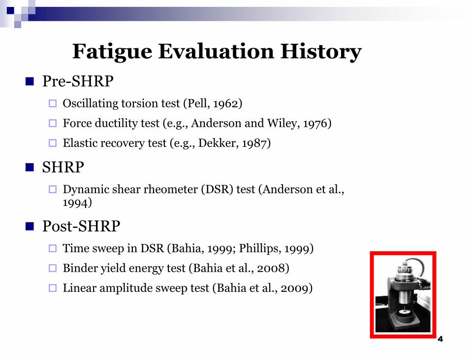
Fatigue Evaluation History
Pre-SHRP
Oscillating torsion test (Pell, 1962)
Force ductility test (e.g., Anderson and Wiley, 1976)
Elastic recovery test (e.g., Dekker, 1987)
SHRP
Dynamic shear rheometer (DSR) test (Anderson et al., 1994)
Post-SHRP
Time sweep in DSR (Bahia, 1999; Phillips, 1999)
Binder yield energy test (Bahia et al., 2008)
Linear amplitude sweep test (Bahia et al., 2009)
4

Problems with Current Binder Fatigue Evaluation
Low temperature and fatigue cracking are high strain fracture processes that cannot be readily captured rheologically.
Fatigue cracking is a non-linear phenomenon.
Micro- and macro-cracking can appear in high stress concentration areas. (Around air voids or large aggregate particles.)
5

Binder Grading Through Fracture Mechanics Based Test Methods
Low-Temperature Failure Brittle fracture energy: GIc or Gf
Crack tip opening displacement (CTOD)
Fatigue FailureDuctile fracture energies: we and wp (essential and
plastic works of fracture, respectively)
Approximate crack tip opening displacement:
CTOD (or δt)= wessential/ net section stress at 5mm
6

Essential Work of Fracture
Ligament lengths (L): 5, 10, 15, 20 and 25 mm
Sample thickness (B): 6.5 mm
Strain rate = 100 mm/min
T = 25oC
L
40 mm
30 mm
7

Data Analysis
Total Work of Fracture:
Wt = We + Wp = LB we + βL2B wp
Total Specific Work of Fracture:
wt = = we + βL wp
Where β is a scaling factor accounting for the shape of the plastic zone.
LB
Wt
8

Experimental Set-up
9

Experimental Design
Fracture Process Zone
We region: essential for fracture and initiates tearing of neck.
Outer Plastic Zone
Wp region:non-essential for fracture.
10

Asphalt Binders Tested
FHWA ALF
PG Grade, ºC
G*sinδ at 25ºC,
MPa
Control (L2)
Airblown (L3)
SBS (L4)
CRTB (L5)
RET (L6)
SB (L9)
72-23
74-28
74-28
79-28
74-31
71-28
5.33
3.58
1.44
2.11
1.16
0.56
11
SBS =styrene-butadiene-styrene linear triblock copolymerCRTB = crumb rubber as blended according to a terminal processRET = reactive ethylene terpolymerSB = styrene-butadiene copolymer

Typical Raw DataF
orc
e (N
)
Extension (mm)
00
30
100
Strain Rate = 100 mm/min
T = 25oC
50 150
90
60
L= 5 10 15 20 25
ControlControl
L= 5 10 15 20 25
12

Typical Raw DataF
orc
e (N
)
Extension (mm)
00
10
120
Strain Rate = 100 mm/min
T = 25oC
60 180
30
20
L= 5 10 15 20 25
SB diblockSB diblock
L= 5 10 15 20 25
13

Typical Raw DataF
orc
e (N
)
Extension (mm)
00
10
200
Strain Rate = 100 mm/min
T = 25oC
100 300
30
20
L= 5 10 15 20
25
SBS linearSBS linear
L= 5 10 15 20
25
14

Determination of Essential and Plastic Works of Fracture
wt, kJ m-2
Ligament Length, mm
0 10 20 300
20
40
L2 Control
L3 Airblown
L4 SBS
L5 CRTB
L6 RET
L9 SB
15

Ductile vs. Essential Works of FractureBinders from FHWA ALF
e
0
0.2
0.4
0.6
0.8
1
1.2
0 2 4 6 8 10 12 14
β wp, MJ.m-3
w , kJ.m-2
L-2 Control
L-9 SB
L-3 Airblown
L-4 SBS
L-5 CRTB
L-6 RET
BEST
WORST
16

Net Section Stresses as a Function of the Ligament Length
=L3 Airblown, =L2 Control, =L5 CRTB, =L4 SBS, =L6 RET, =L9 SB
0
0.5
1
1.5
0 5 10 15 20 25 30
Ligament Length, mm
17

L2 Control L3 Airblown L4 SBS L5 CRTB L6 RET
0.0
10.0
20.0
30.0
Binder
7.5 6.8
24
8.5
15.7
Crack Tip Opening Displacements
18

FHWA Turner-Fairbanks ALF
19

Super-Single Loading Wheel(16,000 lbs and 19oC)
20
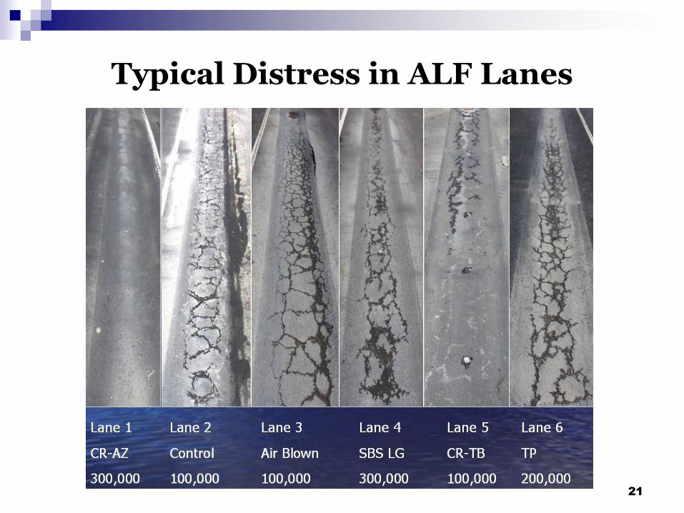
Typical Distress in ALF Lanes
21

Fatigue Cracking Rates
0.1
1
10
100
1000
1000 10000 100000 1000000
Number of Load Applications
=L3 Airblown, =L2 Control, =L5 CRTB, =L6 RET, =L4 SBS, =L7 F
22

Binder CTOD vs. Fatigue Cracking Rates
0.01
0.1
1
10
1.0 10.0 100.0Cra
ck R
ate
to 2
0 m
, m
m/p
ass
Binder CTOD, mm
L2
L3
L4L5
L6
23

0.01
0.1
1
10
0.1 1 10 100
Loss Modulus, MPa
L2
L3
L4
L5L6
Binder Loss Modulus vs. Fatigue Cracking Rates
@ 10rad/s and T = 25ºC
24

CTOD values of Recovered Binders
Strain Rate = 50 mm/min
T = 25oC
Lane # Lane 2 (Control) Lane 3 (Airblown) Lane 4 (SBS)
Aging Level Natural Accelerated Natural Accelerated Natural Accelerated
Lane Site S3 S4 S3 S4 S3 S4
CTOD (mm) 8.5 7.2 8.8 7.4 12.6 8.9
26

Fracture in ALF Mixtures
Fracture process zone has elliptical shape.Strain Rate=0.5 mm/min, T = 19ºC
27
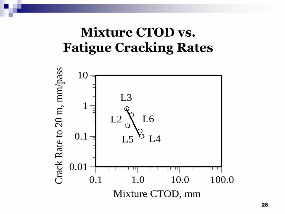
Mixture CTOD vs. Fatigue Cracking Rates
0.01
0.1
1
10
0.1 1.0 10.0 100.0Cra
ck R
ate
to 2
0 m
, m
m/p
ass
Mixture CTOD, mm
L2
L3
L4L5
L6
28

Conclusions
EWF test method can be used to provide ductile failure properties of binders and mixtures
No correlation found between CTOD and Loss Modulus, G*sinδ
Binder and Mixture CTOD appears to correlate well with fatigue distress in FHWA ALF trial
29
Questions
30

Sample after fracture at 0oC under
stable crack growth conditions
31