Embed Size (px)
Citation preview
SPECTROSCOPIC TECHNIQUES
A Simple Device for Diffuse Reflectance Fourier Transform Infrared Spectroscopy
HANS MAULHARDT and D I E T M A R KUNATH*
Academy of Sciences of GDR, Central Institute for Physical Chemistry, DDR- 1199 Berlin, German Demo- cratic Republic
Index Headings: Fourier transform infrared spec- troscopy; Diffuse reflectance measurement; Tech- n iques , spectroscopic.
Investigations of solids, especially of powders, are of great interest in infrared spectroscopy. The applicability of transmission or a t tenuated total reflectance (ATR) techniques is often limited by the scattering of the radia- tion. This scattering can be spectrally analyzed, if the diffuse reflected radiation can be collected and transfered to the infrared detector.
The methods used in the ultraviolet and visible spec- tral region (see the monographs of Kort i im 1 and Wen- dlandt and Hecht 2) are not applicable in the infrared, because they provide only a small radiat ion output to the detector, whereas the lower sensitivity of the infrared detector requires a high output of radiat ion impinging upon the detector to get a useful signal/noise-ratio.
The use of an hemispherical mirror or, with be t te r focusing properties, an hemiellipsoidal mirror is the most effective principle. Recent ly Kort i im and Delfs 3 used at first an off-axis ellipsoidal mirror and Blevin and Brown 4 an on-axis one. Comparing the results of Brandenberg 5 and Heinisch e t al . , ~ who studied the focusing propert ies of off-axis mirrors, and Dunn e t a l . , 7 who described the properties of an on-axis ellipsoid, the former type seems to provide the higher efficiency in radiation output. Therefore, this principle was used by us for the construc- tion of a double-beam spectrometer with prism mono- chromator.8. 9
The necessary sequence of optical elements in a diffuse reflectance spectrometer is (1) radiation source, (2) monochromator , (3) sample, and (4) detector. This se- quence is not given in monochromator instruments under ordinary circumstances but is available in Fourier trans-
Received 24 November 1979. * Author to whom correspondence should be addressed.
Volume 34, Number 3, 1980
form spectrometers, in which there is an in terferometer instead of the monochromator .
The first Fourier t ransform spect rometer with a diffuse reflection device was described by Willey. 1° The spheres used to collect the scat tered radiation are fit ted with diffuse reflecting gold which is very ineffective in radia- tion output.
The arrangement proposed by Fuller and Griffiths 11' 12 is more effective. Th ey use an on-axis ellipsoidal mirror having some disadvantages: the sample must be small to avoid a shadow on the detector, and an additional com- plicated paraboloidal mirror is necessary to overcome the bad focusing propert ies (the il luminated area on the detector is 20 times greater than the area on the sample).
We constructed a diffuse reflecting device for the Four- ier t ransform spectrometer FTS-20 (Digilab, Inc., Cam- bridge, MA) using an off-axis ellipsoidal mirror. There- fore, we need not discuss the dual beam principle, because the interferometer is not measuring the quotient of the intensities of both beams like a monochromator spec- t rometer , but the division is a computer ratio of two signals. The single beam technique eliminates the need for two accessories and allows a higher ou tput of radia- tion. The areas of the sample and the detector must not lie in the same plane but should be sloped advantageously about 17 ° to the opening of the ellipsoidal mirror, so tha t the angular width of the most intensive reflection of the sample and the opening angle of the detector are over- lapping on the reflecting surface of the mirror. 13
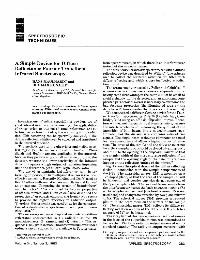
Fig. 1 shows the optical design of the diffuse reflecting device in connection with the sample compar tment of the FTS. The ellipsoidal mirror (EM) is mounted on a 17 ° sloped plane, so tha t the area of the sample (S) will be horizontal and powder particles do not come out of the open sample holder. The incident beam coming from the interferometer passes the back entrance opening (B) of the sample compar tment [the front opening (F) is not used here] and changes its direction by two plane mirrors (PM). The spherical mirror (SM) provides a reduced picture of the beam focus on the surface of the sample (S). The ellipsoidal mirror (EM) collects its diffuse re- flecting radiation on area of the detector (D) which has an angle of 34 ° to the horizontal.
The stray light of this device, measured without sample in the focus of the ellipsoidal mirror, was determined to be less than 1% of the radiation output measured with a standard sample.i- The radiation output measured with
t A rough glass plate covered with evaporated gold was used for the reflectance standard, since there are no materials having diffuse reflectance near 1 all over the infrared regionJ 4' ~'
APPLIED SPECTROSCOPY 383
• st4
\
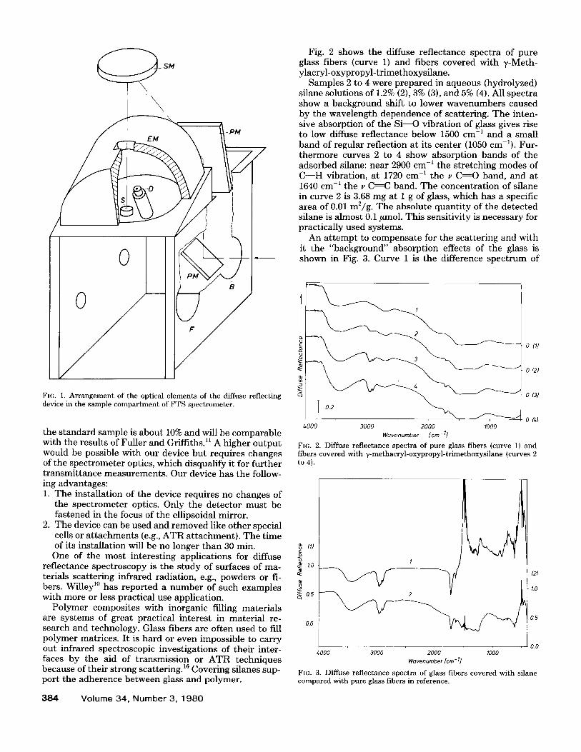
Fig. 2 shows the diffuse reflectance spectra of pure glass fibers (curve 1) and fibers covered with y-Meth- ylacryl-oxypropyl-tr imethoxysflane.
Samples 2 to 4 were prepared in aqueous (hydrolyzed) silane solutions of 1.2% (2), 3% (3), and 5% (4). All spectra show a background shift to lower wavenumbers caused by the wavelength dependence of scattering. The inten- sive absorption of the S i - -O vibration of glass gives rise to low diffuse reflectance below 1500 cm -1 and a small band of regular reflection at its center (1050 cm-l). Fur- thermore curves 2 to 4 show absorpt ion bands of the adsorbed sflane: near 2900 cm -~ the stretching modes of C - - H vibration, at 1720 cm -~ the ~, C-~-O band, and at 1640 cm -~ the ~, C : C band. Th e concentra t ion of sflane in curve 2 is 3.68 mg at 1 g of glass, which has a specific area of 0.01 m2/g. Th e absolute quant i ty of the detected silane is almost 0.1/zmol. This sensitivity is necessary for practically used systems.
An a t t empt to compensate for the scattering and with it the "background" absorption effects of the glass is shown in Fig. 3. Curve 1 is the difference spect rum of
Fro. 1. Arrangement of the optical elements of the diffuse reflecting device in the sample compartment of FTS spectrometer.
the s tandard sample is about 10% and will be comparable with the results of Fuller and Griffiths.ll A higher ou tput would be possible with our device but requires changes of the spect rometer optics, which disqualify it for fur ther t ransmit tance measurements . Our device has the follow- ing advantages: 1. The installation of the device requires no changes of
the spect rometer optics. Only the detector must be fastened in the focus of the ellipsoidal mirror.
2. The device can be used and removed like other special cells or a t tachments (e.g., A T R at tachment) . T h e t ime of its installation will be no longer than 30 min.
One of the most interesting applications for diffuse reflectance spectroscopy is the s tudy of surfaces of ma- terials scattering infrared radiation, e.g., powders or fi- bers. Willey 1° has repor ted a number of such examples with more or less practical use application.
Polymer composites with inorganic filling materials are systems of great practical interest in material re- search and technology. Glass fibers are often used to fill polymer matrices. It is hard or even impossible to carry out infrared spectroscopic investigations of their inter- faces by the aid of transmission or A T R techniques because of their strong scattering. 16 Covering silanes sup- port the adherence between glass and polymer.
384 Volume 34, Number 3, 1980
4000 3 0 0 0 2000 1000 Wavenumber [cm -1]
FIG. 2. Diffuse reflectance spectra of pure glass fibers (curve 1) and fibers covered with 7-methacryl-oxypropyl-trimethoxysilane (curves 2 to 4).
0 (I)
0 (2)
0(3)
0 (4)
(1)
,~ 1.o
0.5
0.0
1
1.o
0 5
0.0 4000 3000 2000 I000
Wavenumber [cm- I]
FIG. 3. Diffuse reflectance spectra of glass fibers covered with sflane compared with pure glass fibers in reference.
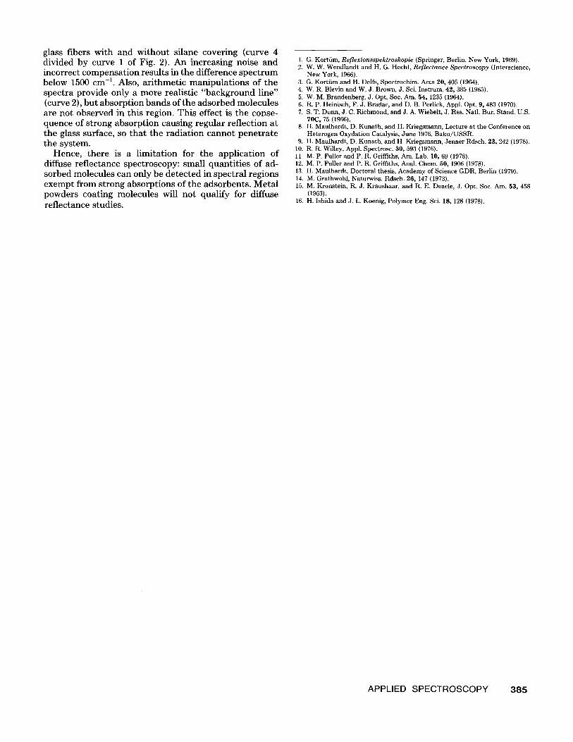
glass fibers with and without silane covering (curve 4 divided by curve 1 of Fig. 2). An increasing noise and incorrect compensation results in the difference spectrum below 1500 cm -1. Also, arithmetic manipulations of the spectra provide only a more realistic "background line" (curve 2), but absorption bands of the adsorbed molecules are not observed in this region. This effect is the conse- quence of strong absorption causing regular reflection at the glass surface, so that the radiation cannot penetrate the system.
Hence, there is a limitation for the application of diffuse reflectance spectroscopy: small quantities of ad- sorbed molecules can only be detected in spectral regions exempt from strong absorptions of the adsorbents. Metal powders coating molecules will not qualify for diffuse reflectance studies.
1. G. Kortiim, Reflexionsspektroskopie (Springer, Berlin, New York, 1969). 2. W. W. Wendlandt and H. G. Hecht, Reflectance Spectroscopy (Interscience,
New York, 1966). 3. G. Kortiim and H. Dells, Spectrochim. Acta 20, 405 (1964). 4. W. R. Blevin and W. J. Brown, J. Sci. Instrum. 42, 385 (1965). 5. W. M. Brandenberg, J. Opt. Soc. Am. 54, 1235 (1964). 6. R. P. Heinisch, F. J. Bradac, and D, B. Perlick, Appl. Opt. 9, 483 (1970). 7. S. T. Dunn, J. C. Richmond, and J. A. Wiebelt, J. Res. Natl. Bur. Stand. U.S.
70C, 75 (1966). 8. H. Maulhardt, D. Kunath, and H. Kriegsmann, Lecture at the Conference on
Heterogen Oxydation Catalysis, June 1976, Baku/USSR. 9. H. Maulhardt, D. Kunath, and H. Kriegsmann, Jenaer Rdsch. 23, 242 (1978).
10. R. R. Willey, Appl. Spectrosc. 30, 593 (1976). 11. M. P. Fuller and P. R. Griffiths, Am. Lab. 10, 69 (1978). 12. M. P. Fuller and P. R. Griffiths, Anal. Chem. 50, 1906 (1978). 13. H. Maulhardt, Doctoral thesis, Academy of Science GDR, Berlin (1979). 14. M. Grathwohl, Naturwiss. Rdsch. 26, 147 (1973). 15. M. Kronstein, R. J. Kraushaar, and R. E. Deacle, J. Opt. Soc. Am, 53, 458
(1963}. 16. H. Ishida and J. L. Koenig, Polymer Eng. Sci. 18, 128 (1978).
APPLIED SPECTROSCOPY 385