Embed Size (px)
Citation preview
U.S Patent Application of Stephen M. Lord � Page 1 of 30
A set of processes for removing impurities from a silicon production facility
5
U.S. Patent Application of:
Stephen Michael Lord.
10
"Express mail" mailing label number _____________________________ Date of Deposit: 07/29/05____________ 15 I hereby certify that this correspondence, including the attachments listed on the accompanying New Utility Patent Application Transmittal, is being deposited with the United States Postal Service "Express Mail Post Office to Addressee" 20 service under 37 CFR 1.10 on the date indicated above and is addressed to Mail Stop Patent Applications Commissioner for Patents P.O. Box 1450 25 Alexandria, VA 22313-1450. Stephen M. Lord ____________________________________________ (Typed or printed name of person mailing paper or fee) 30 ____________________________________________
(Signature of person mailing paper or fee)
U.S Patent Application of Stephen M. Lord � Page 2 of 30
Title of the Invention
A set of processes for removing impurities from a silicon production facility
Cross Reference to Related Applications 5
Not Applicable
Statement Regarding Federally Sponsored Research or Development
Not Applicable
10
Description of Attached Appendix
Not Applicable
Background of the Invention
This invention relates generally to the field of high purity silicon production and 15
within that field to the conversion of metallurgical grade silicon to electronic grade
silicon and yet more specifically to a set of three processes for removing impurities from
a silicon production facility. One or more of the processes may be used to prevent
buildup of impurities in recycle streams and to provide a purer and more stable
feedstock to the final purification steps of the standard distillation techniques commonly 20
used to purify a high purity silicon containing gas, which is then used to produce high
quality silicon in a deposition reactor, The locations where the impurities are removed
are called sinks and the locations where they enter are called sources. Other definitions
and abbreviations are;
MCS; monochlorosilane, SiH3Cl 25
DCS; dichlorosilane, SiH2Cl2
TCS; Trichlorosilane, SiHCl3
U.S Patent Application of Stephen M. Lord � Page 3 of 30
STC; Silicon Tetrachloride, SiCl4
MBS; monobromosilane, SiH3Br
DBS; dibromosilane, SiH2Br2
TBS; Tribromosilane, SiHBr3
SBC; Silicon Tetrabromide, SiBr4 5
MGS; Metallurgical Grade Silicon
EGS; Electronic Grade Silicon
MTCS; Methyl trichlorosilane, Si(CH3)Cl3
MTBS; Methyl tribromosilane ,Si(CH3)Br3
H2; Hydrogen gas 10
HCl : Hydrogen chloride gas
HBr; Hydrogen Bromide gas
Cl2; Chlorine gas
Br2; Bromine gas
Ppm wt is parts per million by weight 15
Ppma is parts per million atomic
Ppba is parts per billion atomic
The majority of high purity electronic grade silicon is produced from metallurgical grade
silicon, MGS, which is approximately 98% pure. The process converts the solid silicon
into a liquid material, which can be purified then decomposed back to silicon. The initial 20
material is usually trichlorosilane, TCS, although tribromosilane, TBS, has been used
and triiodosilane, SiHI3, could be used. The process involves using carrier chemicals to
transform the solid silicon and recycling the carrier chemicals to reduce waste. as is
shown in Fig1. Some carrier chemicals must be used to reject the impurities, which are
Carbon, C; Boron, B; Phosphorus, P; Aluminum, Al; and other metals. Minimizing the 25
loss of the carrier chemicals for the waste is also desirable. Carrier chemicals consist of
silicon, hydrogen, and a halogen, usually chlorine, in various combinations such as H2,
U.S Patent Application of Stephen M. Lord � Page 4 of 30
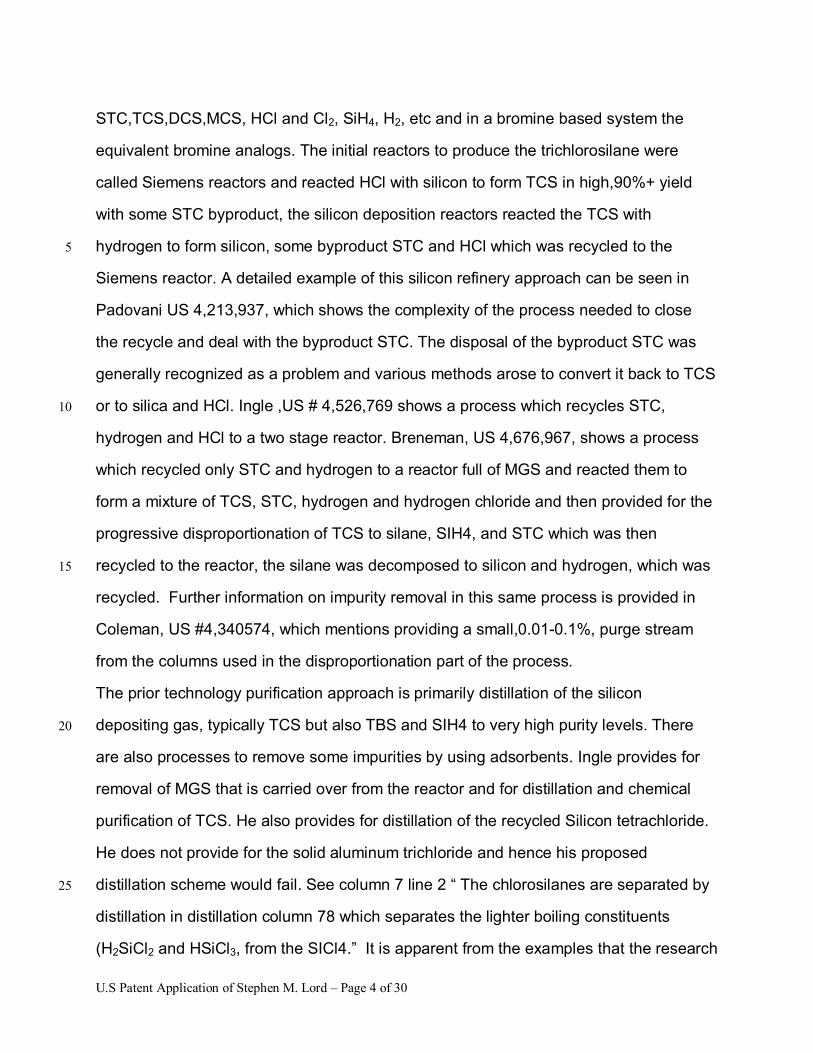
STC,TCS,DCS,MCS, HCl and Cl2, SiH4, H2, etc and in a bromine based system the
equivalent bromine analogs. The initial reactors to produce the trichlorosilane were
called Siemens reactors and reacted HCl with silicon to form TCS in high,90%+ yield
with some STC byproduct, the silicon deposition reactors reacted the TCS with
hydrogen to form silicon, some byproduct STC and HCl which was recycled to the 5
Siemens reactor. A detailed example of this silicon refinery approach can be seen in
Padovani US 4,213,937, which shows the complexity of the process needed to close
the recycle and deal with the byproduct STC. The disposal of the byproduct STC was
generally recognized as a problem and various methods arose to convert it back to TCS
or to silica and HCl. Ingle ,US # 4,526,769 shows a process which recycles STC, 10
hydrogen and HCl to a two stage reactor. Breneman, US 4,676,967, shows a process
which recycled only STC and hydrogen to a reactor full of MGS and reacted them to
form a mixture of TCS, STC, hydrogen and hydrogen chloride and then provided for the
progressive disproportionation of TCS to silane, SIH4, and STC which was then
recycled to the reactor, the silane was decomposed to silicon and hydrogen, which was 15
recycled. Further information on impurity removal in this same process is provided in
Coleman, US #4,340574, which mentions providing a small,0.01-0.1%, purge stream
from the columns used in the disproportionation part of the process.
The prior technology purification approach is primarily distillation of the silicon
depositing gas, typically TCS but also TBS and SIH4 to very high purity levels. There 20
are also processes to remove some impurities by using adsorbents. Ingle provides for
removal of MGS that is carried over from the reactor and for distillation and chemical
purification of TCS. He also provides for distillation of the recycled Silicon tetrachloride.
He does not provide for the solid aluminum trichloride and hence his proposed
distillation scheme would fail. See column 7 line 2 � The chlorosilanes are separated by 25
distillation in distillation column 78 which separates the lighter boiling constituents
(H2SiCl2 and HSiCl3, from the SICl4.� It is apparent from the examples that the research
U.S Patent Application of Stephen M. Lord � Page 5 of 30
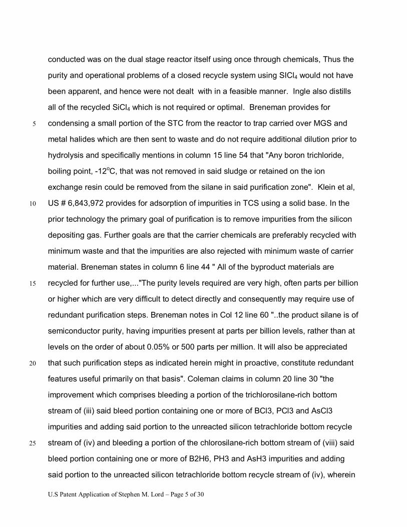
conducted was on the dual stage reactor itself using once through chemicals, Thus the
purity and operational problems of a closed recycle system using SICl4 would not have
been apparent, and hence were not dealt with in a feasible manner. Ingle also distills
all of the recycled SiCl4 which is not required or optimal. Breneman provides for
condensing a small portion of the STC from the reactor to trap carried over MGS and 5
metal halides which are then sent to waste and do not require additional dilution prior to
hydrolysis and specifically mentions in column 15 line 54 that "Any boron trichloride,
boiling point, -12oC, that was not removed in said sludge or retained on the ion
exchange resin could be removed from the silane in said purification zone". Klein et al,
US # 6,843,972 provides for adsorption of impurities in TCS using a solid base. In the 10
prior technology the primary goal of purification is to remove impurities from the silicon
depositing gas. Further goals are that the carrier chemicals are preferably recycled with
minimum waste and that the impurities are also rejected with minimum waste of carrier
material. Breneman states in column 6 line 44 " All of the byproduct materials are
recycled for further use,..."The purity levels required are very high, often parts per billion 15
or higher which are very difficult to detect directly and consequently may require use of
redundant purification steps. Breneman notes in Col 12 line 60 "..the product silane is of
semiconductor purity, having impurities present at parts per billion levels, rather than at
levels on the order of about 0.05% or 500 parts per million. It will also be appreciated
that such purification steps as indicated herein might in proactive, constitute redundant 20
features useful primarily on that basis". Coleman claims in column 20 line 30 "the
improvement which comprises bleeding a portion of the trichlorosilane-rich bottom
stream of (iii) said bleed portion containing one or more of BCl3, PCl3 and AsCl3
impurities and adding said portion to the unreacted silicon tetrachloride bottom recycle
stream of (iv) and bleeding a portion of the chlorosilane-rich bottom stream of (viii) said 25
bleed portion containing one or more of B2H6, PH3 and AsH3 impurities and adding
said portion to the unreacted silicon tetrachloride bottom recycle stream of (iv), wherein
U.S Patent Application of Stephen M. Lord � Page 6 of 30
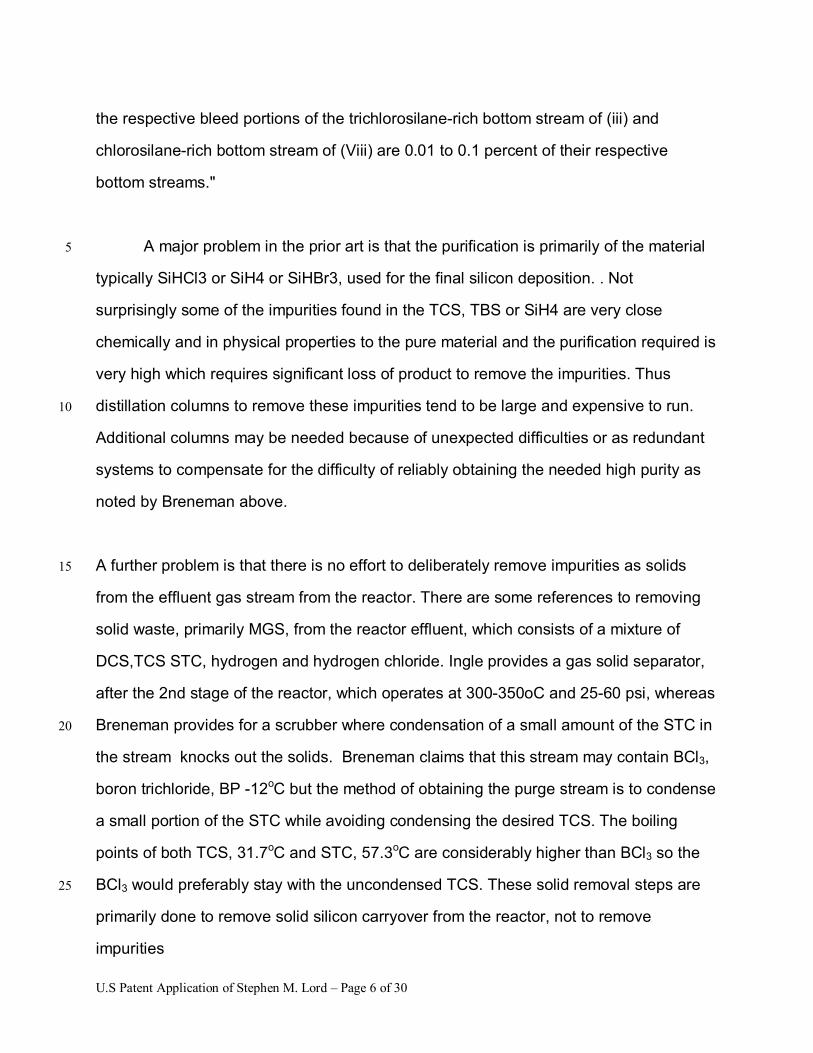
the respective bleed portions of the trichlorosilane-rich bottom stream of (iii) and
chlorosilane-rich bottom stream of (Viii) are 0.01 to 0.1 percent of their respective
bottom streams."
A major problem in the prior art is that the purification is primarily of the material 5
typically SiHCl3 or SiH4 or SiHBr3, used for the final silicon deposition. . Not
surprisingly some of the impurities found in the TCS, TBS or SiH4 are very close
chemically and in physical properties to the pure material and the purification required is
very high which requires significant loss of product to remove the impurities. Thus
distillation columns to remove these impurities tend to be large and expensive to run. 10
Additional columns may be needed because of unexpected difficulties or as redundant
systems to compensate for the difficulty of reliably obtaining the needed high purity as
noted by Breneman above.
A further problem is that there is no effort to deliberately remove impurities as solids 15
from the effluent gas stream from the reactor. There are some references to removing
solid waste, primarily MGS, from the reactor effluent, which consists of a mixture of
DCS,TCS STC, hydrogen and hydrogen chloride. Ingle provides a gas solid separator,
after the 2nd stage of the reactor, which operates at 300-350oC and 25-60 psi, whereas
Breneman provides for a scrubber where condensation of a small amount of the STC in 20
the stream knocks out the solids. Breneman claims that this stream may contain BCl3,
boron trichloride, BP -12oC but the method of obtaining the purge stream is to condense
a small portion of the STC while avoiding condensing the desired TCS. The boiling
points of both TCS, 31.7oC and STC, 57.3oC are considerably higher than BCl3 so the
BCl3 would preferably stay with the uncondensed TCS. These solid removal steps are 25
primarily done to remove solid silicon carryover from the reactor, not to remove
impurities
U.S Patent Application of Stephen M. Lord � Page 7 of 30
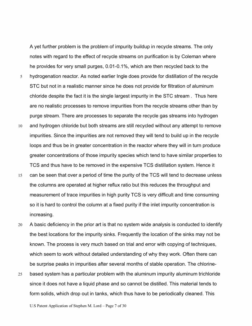
A yet further problem is the problem of impurity buildup in recycle streams. The only
notes with regard to the effect of recycle streams on purification is by Coleman where
he provides for very small purges, 0.01-0.1%, which are then recycled back to the
hydrogenation reactor. As noted earlier Ingle does provide for distillation of the recycle 5
STC but not in a realistic manner since he does not provide for filtration of aluminum
chloride despite the fact it is the single largest impurity in the STC stream . Thus here
are no realistic processes to remove impurities from the recycle streams other than by
purge stream. There are processes to separate the recycle gas streams into hydrogen
and hydrogen chloride but both streams are still recycled without any attempt to remove 10
impurities. Since the impurities are not removed they will tend to build up in the recycle
loops and thus be in greater concentration in the reactor where they will in turn produce
greater concentrations of those impurity species which tend to have similar properties to
TCS and thus have to be removed in the expensive TCS distillation system. Hence it
can be seen that over a period of time the purity of the TCS will tend to decrease unless 15
the columns are operated at higher reflux ratio but this reduces the throughput and
measurement of trace impurities in high purity TCS is very difficult and time consuming
so it is hard to control the column at a fixed purity if the inlet impurity concentration is
increasing.
A basic deficiency in the prior art is that no system wide analysis is conducted to identify 20
the best locations for the impurity sinks. Frequently the location of the sinks may not be
known. The process is very much based on trial and error with copying of techniques,
which seem to work without detailed understanding of why they work. Often there can
be surprise peaks in impurities after several months of stable operation. The chlorine-
based system has a particular problem with the aluminum impurity aluminum trichloride 25
since it does not have a liquid phase and so cannot be distilled. This material tends to
form solids, which drop out in tanks, which thus have to be periodically cleaned. This
U.S Patent Application of Stephen M. Lord � Page 8 of 30
solid is also a Lewis acid and so can form temporary temperature dependent complexes
with phosphorus impurities such as PH4Cl which itself is only stable as a solid,
decomposing to PH3 and HCl on heating. A period of cold weather may provide high
purity then warming may stimulate phosphorus contamination. Alternatively a filter with
this material in may be hit with a warmer than usual stream and contaminate it. Similar 5
problems apply to boron contamination. In some processes such as the silane process
there is no designated sink for boron, it may go through its own disproportionation
process and emerge as diborane, B2H6, to be removed with hydrogenated carbon
compounds such as methane, ethane and ethylene from the silane by cryogenic
distillation or it may bind to the ion exchange resin catalyst. Carbon is present in TCS as 10
the methyl analogues of chlorosilanes, methylchlorosilane, CH3SiCl3, MTCS
dimethylchlorosilane, (CH3)2SiCl2 and the bromine analogs in TBS. It may be removed
in distillation, but its chemical similarity to the TCS and STC suggest the likelihood of
azeotrope formation and even more difficult separation. In the silane system carbon
tracks the silicon in forming methane and other hydrocarbons in the silane from the 15
carbon containing species in the TCS.
The ultimate goal of purification is to remove impurities from metallurgical grade silicon
(MGS) and make high purity silicon but the removal of the impurities is not seen as the
goal, instead the goal is to make high purity material. Thus a primary deficiency in the
prior technology is that the sources and sinks are not closely identified so they may be 20
monitored to prevent surprise buildups. A further major deficiency is that the carrier
chemicals are preferably recycled with minimum waste but no effort is made to evaluate
impurity buildup or remove impurities from these streams. A yet further deficiency is the
failure to evaluate the whole system and select the optimum location for the sinks. A
yet further deficiency is the failure to provide for bypasses on recycle stream so that 25
only a portion of the stream need be purified.
U.S Patent Application of Stephen M. Lord � Page 9 of 30
Brief Summary of the Invention
The primary object of the invention is to provide a consistent way to remove the
impurities from the overall system.
Another object of the invention is to prevent change in impurity concentrations
due to build up in recycle loops. 5
Another object of the invention is to remove impurities in the most cost efficient
locations for that particular impurity.
A further object of the invention is to reduce the impurities in the feed to the high
purity distillation steps.
Yet another object of the invention is to remove both the hydride and the halide 10
forms of the impurities
Still yet another object of the invention is to reduce the cost of the process.
Another object of the invention is to reduce the waste from the process.
Another object of the invention is to use the halogen recovery system to improve
impurity removal 15
A further object of the invention is to have clearly identified sinks for all impurities.
Other objects and advantages of the present invention will become apparent
from the following descriptions, taken in connection with the accompanying drawings,
wherein, by way of illustration and example, an embodiment of the present invention is 20
disclosed.
In accordance with a preferred embodiment of the invention, there is disclosed a
process for removing boron impurities from a silicon production facility comprising the
steps of: providing one or more high temperature solids removal means to remove
boron as solid titanium diboride from a reactor effluent stream containing primarily 25
halosilanes, hydrogen and hydrogen halides by preventing substantial contact between
the titanium diboride and the hydrogen halide below a reaction temperature where the
U.S Patent Application of Stephen M. Lord � Page 10 of 30
reaction temperature is preferably greater than 200oC, more preferably greater than
300oC and most preferably greater than 400oC.
In accordance with a preferred embodiment of the invention, there is disclosed a
process for removing certain carbon, primarily methane, and/or phosphorus, primarily
phosphine, impurities from a silicon production facility comprising the steps of: cooling a 5
reactor effluent stream containing primarily halosilanes, hydrogen and hydrogen
halides, condensing more than 50% of the halosilanes, separating the preponderance of
the uncondensed gases from the condensed liquids and passing some or all the gases
through a membrane system to remove greater than 50% of any methane present
and/or any phosphine present , and recovering greater than 50% of the hydrogen 10
present. .
In accordance with a preferred embodiment of the invention, there is disclosed a
process for removing certain carbon, phosphorus and metal impurities from a
silicon production facility comprising the steps of: separating the halosilanes into
at least two streams one low boiling and one high boiling, which latter stream 15
also contains the preponderance of any carbon, phosphorus and metal
impurities and then further processing all or part of the latter stream to provide a
stream containing the preponderance of the high boiling halosilanes with less
than 50% of the incoming impurities and one or more streams concentrated in
impurities. 20
In a modified embodiment of the above process suitable for chlorosilanes only, an
additional step is provided for removal of aluminum as aluminum trichloride by
filtration of one or more liquid halosilanes stream.
In a yet further modification of this embodiment suitable only for bromosilanes a stream
containing a mixture of TBS and STB , which contains the carbon impurity, MTBS 25
is removed from the system and sent to waste.
U.S Patent Application of Stephen M. Lord � Page 11 of 30
Yet further modifications of this embodiment may be provided to obtain this stream as
will be apparent to someone familiar with the art of removing impurities, which
occur between the boiling points of the major components entering a distillation
process. Such modifications include but are not limited to; removing a stream
from the initial separation device which is located between the withdrawal points 5
of the low boiling and high boiling components; allowing the impurity MTBS to
enter the low boiling stream and then removing it from the low boiling stream in a
further separation process and allowing the impurity MTBS to enter the high
boiling stream and then removing it from the high boiling stream in a yet further
separation process. 10
As part of this overall process it is anticipated that further techniques will be provided to
provide the required high purity material for deposition and that techniques will also be
provided to recover all or part of the halogen present in the waste streams and to 15
circulate recycle streams providing only that the design of the waste recovery system
provides sinks for all the impurities and does not recycle significant quantities of
impurities to the system with the recovered halogen. Significant is defined in
relationship to the amount of impurities entering the MGS reactor from other sources
and should be below 50% and preferably below 10% and most preferably below 1%. It 20
will be apparent to those familiar with the art that the purpose of removing impurities to
a waste recovery unit is defeated if the design of the unit recycles the impurities and
that various techniques exist to prevent this. Such techniques include but are not
restricted to selecting certain streams to bypass the halogen recovery step altogether,
and designing impurity removal steps into the halogen recovery portion of waste 25
recovery.
U.S Patent Application of Stephen M. Lord � Page 12 of 30
Brief Description of the Drawings
The drawings constitute a part of this specification and include exemplary
embodiments to the invention, which may be embodied in various forms. It is to be
understood that in some instances various aspects of the invention may be shown 5
exaggerated or enlarged to facilitate an understanding of the invention.
Figure 1 is a conceptual schematic of the process of converting metallurgical
grade silicon to electronic grade silicon.
Figure 2 is a process schematic of the process of converting metallurgical grade 10
silicon to electronic grade silicon with more detail of the recycle of the carrier chemicals.
Figure 2a is a modification of Figure 2 to show the new process schematic with
the location of the three new processes and the new waste streams
Figure 3 is an example of the Membrane Separator process
Figure 4a is an example of the High boiling Halosilane impurity removal process 15
as applied to a bromosilanes based process
Figure 4b is an example of the High boiling Halosilane impurity removal process
as applied to a chlorosilanes based process
Figure 5 is a chart illustrating the change in boron species with temperature as
the reactor effluent cools 20
Figure 6 is an example of the removal of solid boron species from reactor effluent
U.S Patent Application of Stephen M. Lord � Page 13 of 30
Detailed Description of the Preferred Embodiments
Detailed descriptions of the preferred embodiment are provided herein. It is to be
understood, however, that the present invention may be embodied in various forms.
Therefore, specific details disclosed herein are not to be interpreted as limiting, but
rather as a basis for the claims and as a representative basis for teaching one skilled in 5
the art to employ the present invention in virtually any appropriately detailed system,
structure or manner.
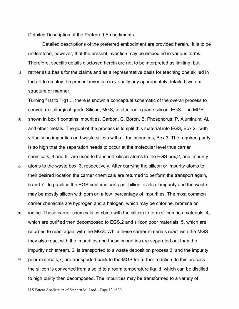
Turning first to Fig1 ... there is shown a conceptual schematic of the overall process to
convert metallurgical grade Silicon, MGS, to electronic grade silicon, EGS. The MGS
shown in box 1 contains impurities, Carbon, C, Boron, B, Phosphorus, P, Aluminum, Al, 10
and other metals. The goal of the process is to split this material into EGS, Box 2, with
virtually no impurities and waste silicon with all the impurities, Box 3. The required purity
is so high that the separation needs to occur at the molecular level thus carrier
chemicals, 4 and 6, are used to transport silicon atoms to the EGS box,2, and impurity
atoms to the waste box, 3, respectively. After carrying the silicon or impurity atoms to 15
their desired location the carrier chemicals are returned to perform the transport again,
5 and 7. In practice the EGS contains parts per billion levels of impurity and the waste
may be mostly silicon with ppm or a low percentage of impurities. The most common
carrier chemicals are hydrogen and a halogen, which may be chlorine, bromine or
iodine. These carrier chemicals combine with the silicon to form silicon rich materials, 4, 20
which are purified then decomposed to EGS,2 and silicon poor materials, 5, which are
returned to react again with the MGS. While these carrier materials react with the MGS
they also react with the impurities and these impurities are separated out then the
impurity rich stream, 6, is transported to a waste deposition process,3, and the impurity
poor materials,7, are transported back to the MGS for further reaction. In this process 25
the silicon is converted from a solid to a room temperature liquid, which can be distilled
to high purity then decomposed. The impurities may be transformed to a variety of
U.S Patent Application of Stephen M. Lord � Page 14 of 30
species, which may be solid, liquid or gas and which may be halides, hydrides,
hydrohalides or contain silicon in addition to halides and hydrogen. As can be seen
conceptually the impurity poor stream returning to the MGS reactor may contain
significant amounts of impurities. Since the impurity separation is not absolute but is
instead a fractional split of the impurities between the EGS, 2, and the waste, 3, an 5
increase in the amount of impurities, caused by recycle of impurities, will increase the
impurities in the EGS. It is important to note that the dashed line 8. represents the
many impurities that are allowed to build up in the reactor and only removed periodically
when the reactor is emptied and refilled.
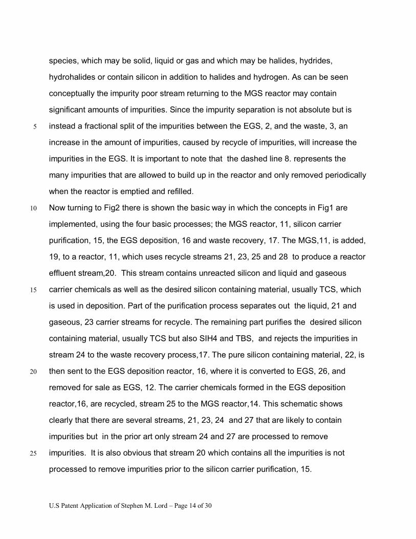
Now turning to Fig2 there is shown the basic way in which the concepts in Fig1 are 10
implemented, using the four basic processes; the MGS reactor, 11, silicon carrier
purification, 15, the EGS deposition, 16 and waste recovery, 17. The MGS,11, is added,
19, to a reactor, 11, which uses recycle streams 21, 23, 25 and 28 to produce a reactor
effluent stream,20. This stream contains unreacted silicon and liquid and gaseous
carrier chemicals as well as the desired silicon containing material, usually TCS, which 15
is used in deposition. Part of the purification process separates out the liquid, 21 and
gaseous, 23 carrier streams for recycle. The remaining part purifies the desired silicon
containing material, usually TCS but also SIH4 and TBS, and rejects the impurities in
stream 24 to the waste recovery process,17. The pure silicon containing material, 22, is
then sent to the EGS deposition reactor, 16, where it is converted to EGS, 26, and 20
removed for sale as EGS, 12. The carrier chemicals formed in the EGS deposition
reactor,16, are recycled, stream 25 to the MGS reactor,14. This schematic shows
clearly that there are several streams, 21, 23, 24 and 27 that are likely to contain
impurities but in the prior art only stream 24 and 27 are processed to remove
impurities. It is also obvious that stream 20 which contains all the impurities is not 25
processed to remove impurities prior to the silicon carrier purification, 15.
U.S Patent Application of Stephen M. Lord � Page 15 of 30
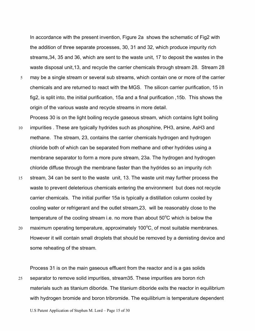
In accordance with the present invention, Figure 2a shows the schematic of Fig2 with
the addition of three separate processes, 30, 31 and 32, which produce impurity rich
streams,34, 35 and 36, which are sent to the waste unit, 17 to deposit the wastes in the
waste disposal unit,13, and recycle the carrier chemicals through stream 28. Stream 28
may be a single stream or several sub streams, which contain one or more of the carrier 5
chemicals and are returned to react with the MGS. The silicon carrier purification, 15 in
fig2, is split into, the initial purification, 15a and a final purification ,15b. This shows the
origin of the various waste and recycle streams in more detail.
Process 30 is on the light boiling recycle gaseous stream, which contains light boiling
impurities . These are typically hydrides such as phosphine, PH3, arsine, AsH3 and 10
methane. The stream, 23, contains the carrier chemicals hydrogen and hydrogen
chloride both of which can be separated from methane and other hydrides using a
membrane separator to form a more pure stream, 23a. The hydrogen and hydrogen
chloride diffuse through the membrane faster than the hydrides so an impurity rich
stream, 34 can be sent to the waste unit, 13. The waste unit may further process the 15
waste to prevent deleterious chemicals entering the environment but does not recycle
carrier chemicals. The initial purifier 15a is typically a distillation column cooled by
cooling water or refrigerant and the outlet stream,23, will be reasonably close to the
temperature of the cooling stream i.e. no more than about 50oC which is below the
maximum operating temperature, approximately 100oC, of most suitable membranes. 20
However it will contain small droplets that should be removed by a demisting device and
some reheating of the stream.
Process 31 is on the main gaseous effluent from the reactor and is a gas solids
separator to remove solid impurities, stream35. These impurities are boron rich 25
materials such as titanium diboride. The titanium diboride exits the reactor in equilibrium
with hydrogen bromide and boron tribromide. The equilibrium is temperature dependent
U.S Patent Application of Stephen M. Lord � Page 16 of 30
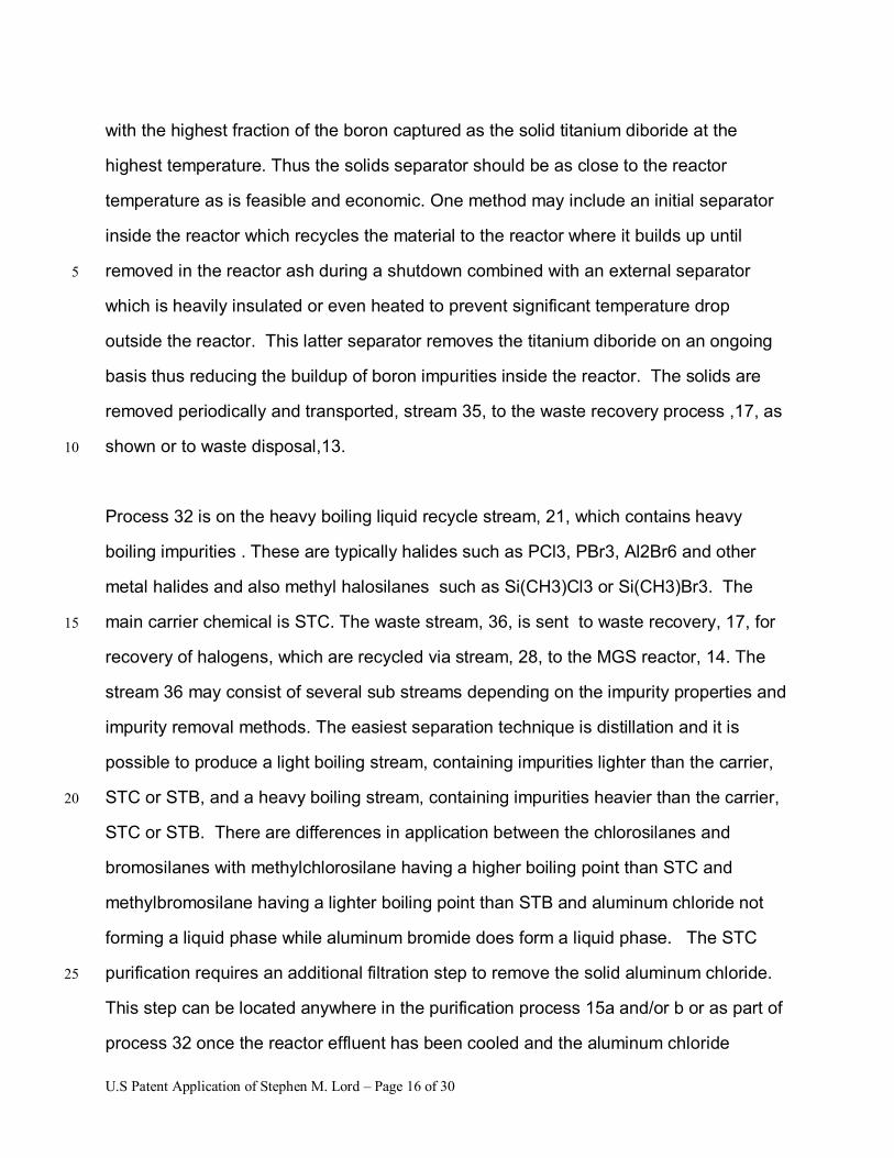
with the highest fraction of the boron captured as the solid titanium diboride at the
highest temperature. Thus the solids separator should be as close to the reactor
temperature as is feasible and economic. One method may include an initial separator
inside the reactor which recycles the material to the reactor where it builds up until
removed in the reactor ash during a shutdown combined with an external separator 5
which is heavily insulated or even heated to prevent significant temperature drop
outside the reactor. This latter separator removes the titanium diboride on an ongoing
basis thus reducing the buildup of boron impurities inside the reactor. The solids are
removed periodically and transported, stream 35, to the waste recovery process ,17, as
shown or to waste disposal,13. 10
Process 32 is on the heavy boiling liquid recycle stream, 21, which contains heavy
boiling impurities . These are typically halides such as PCl3, PBr3, Al2Br6 and other
metal halides and also methyl halosilanes such as Si(CH3)Cl3 or Si(CH3)Br3. The
main carrier chemical is STC. The waste stream, 36, is sent to waste recovery, 17, for 15
recovery of halogens, which are recycled via stream, 28, to the MGS reactor, 14. The
stream 36 may consist of several sub streams depending on the impurity properties and
impurity removal methods. The easiest separation technique is distillation and it is
possible to produce a light boiling stream, containing impurities lighter than the carrier,
STC or STB, and a heavy boiling stream, containing impurities heavier than the carrier, 20
STC or STB. There are differences in application between the chlorosilanes and
bromosilanes with methylchlorosilane having a higher boiling point than STC and
methylbromosilane having a lighter boiling point than STB and aluminum chloride not
forming a liquid phase while aluminum bromide does form a liquid phase. The STC
purification requires an additional filtration step to remove the solid aluminum chloride. 25
This step can be located anywhere in the purification process 15a and/or b or as part of
process 32 once the reactor effluent has been cooled and the aluminum chloride
U.S Patent Application of Stephen M. Lord � Page 17 of 30
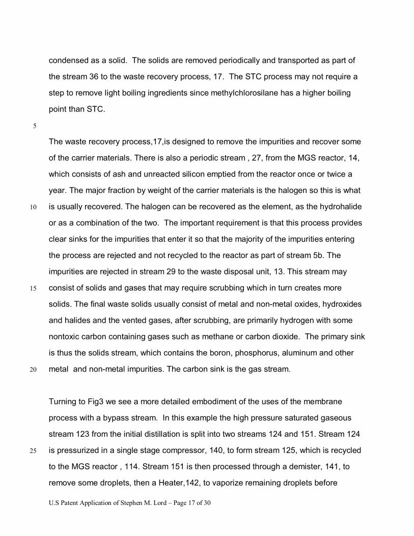
condensed as a solid. The solids are removed periodically and transported as part of
the stream 36 to the waste recovery process, 17. The STC process may not require a
step to remove light boiling ingredients since methylchlorosilane has a higher boiling
point than STC.
5
The waste recovery process,17,is designed to remove the impurities and recover some
of the carrier materials. There is also a periodic stream , 27, from the MGS reactor, 14,
which consists of ash and unreacted silicon emptied from the reactor once or twice a
year. The major fraction by weight of the carrier materials is the halogen so this is what
is usually recovered. The halogen can be recovered as the element, as the hydrohalide 10
or as a combination of the two. The important requirement is that this process provides
clear sinks for the impurities that enter it so that the majority of the impurities entering
the process are rejected and not recycled to the reactor as part of stream 5b. The
impurities are rejected in stream 29 to the waste disposal unit, 13. This stream may
consist of solids and gases that may require scrubbing which in turn creates more 15
solids. The final waste solids usually consist of metal and non-metal oxides, hydroxides
and halides and the vented gases, after scrubbing, are primarily hydrogen with some
nontoxic carbon containing gases such as methane or carbon dioxide. The primary sink
is thus the solids stream, which contains the boron, phosphorus, aluminum and other
metal and non-metal impurities. The carbon sink is the gas stream. 20
Turning to Fig3 we see a more detailed embodiment of the uses of the membrane
process with a bypass stream. In this example the high pressure saturated gaseous
stream 123 from the initial distillation is split into two streams 124 and 151. Stream 124
is pressurized in a single stage compressor, 140, to form stream 125, which is recycled 25
to the MGS reactor , 114. Stream 151 is then processed through a demister, 141, to
remove some droplets, then a Heater,142, to vaporize remaining droplets before
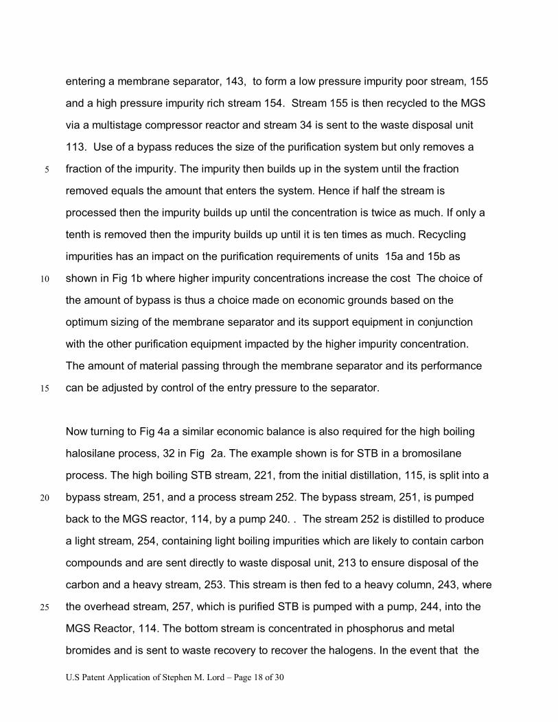
U.S Patent Application of Stephen M. Lord � Page 18 of 30
entering a membrane separator, 143, to form a low pressure impurity poor stream, 155
and a high pressure impurity rich stream 154. Stream 155 is then recycled to the MGS
via a multistage compressor reactor and stream 34 is sent to the waste disposal unit
113. Use of a bypass reduces the size of the purification system but only removes a
fraction of the impurity. The impurity then builds up in the system until the fraction 5
removed equals the amount that enters the system. Hence if half the stream is
processed then the impurity builds up until the concentration is twice as much. If only a
tenth is removed then the impurity builds up until it is ten times as much. Recycling
impurities has an impact on the purification requirements of units 15a and 15b as
shown in Fig 1b where higher impurity concentrations increase the cost The choice of 10
the amount of bypass is thus a choice made on economic grounds based on the
optimum sizing of the membrane separator and its support equipment in conjunction
with the other purification equipment impacted by the higher impurity concentration.
The amount of material passing through the membrane separator and its performance
can be adjusted by control of the entry pressure to the separator. 15
Now turning to Fig 4a a similar economic balance is also required for the high boiling
halosilane process, 32 in Fig 2a. The example shown is for STB in a bromosilane
process. The high boiling STB stream, 221, from the initial distillation, 115, is split into a
bypass stream, 251, and a process stream 252. The bypass stream, 251, is pumped 20
back to the MGS reactor, 114, by a pump 240. . The stream 252 is distilled to produce
a light stream, 254, containing light boiling impurities which are likely to contain carbon
compounds and are sent directly to waste disposal unit, 213 to ensure disposal of the
carbon and a heavy stream, 253. This stream is then fed to a heavy column, 243, where
the overhead stream, 257, which is purified STB is pumped with a pump, 244, into the 25
MGS Reactor, 114. The bottom stream is concentrated in phosphorus and metal
bromides and is sent to waste recovery to recover the halogens. In the event that the
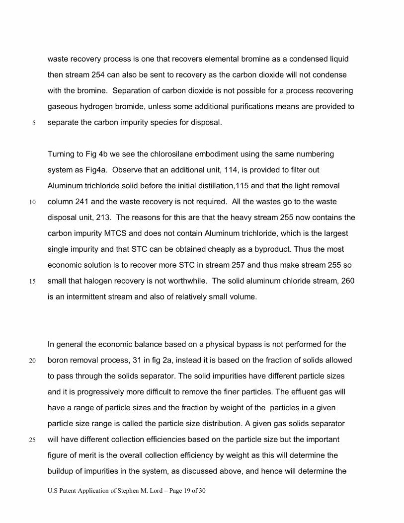
U.S Patent Application of Stephen M. Lord � Page 19 of 30
waste recovery process is one that recovers elemental bromine as a condensed liquid
then stream 254 can also be sent to recovery as the carbon dioxide will not condense
with the bromine. Separation of carbon dioxide is not possible for a process recovering
gaseous hydrogen bromide, unless some additional purifications means are provided to
separate the carbon impurity species for disposal. 5
Turning to Fig 4b we see the chlorosilane embodiment using the same numbering
system as Fig4a. Observe that an additional unit, 114, is provided to filter out
Aluminum trichloride solid before the initial distillation,115 and that the light removal
column 241 and the waste recovery is not required. All the wastes go to the waste 10
disposal unit, 213. The reasons for this are that the heavy stream 255 now contains the
carbon impurity MTCS and does not contain Aluminum trichloride, which is the largest
single impurity and that STC can be obtained cheaply as a byproduct. Thus the most
economic solution is to recover more STC in stream 257 and thus make stream 255 so
small that halogen recovery is not worthwhile. The solid aluminum chloride stream, 260 15
is an intermittent stream and also of relatively small volume.
In general the economic balance based on a physical bypass is not performed for the
boron removal process, 31 in fig 2a, instead it is based on the fraction of solids allowed 20
to pass through the solids separator. The solid impurities have different particle sizes
and it is progressively more difficult to remove the finer particles. The effluent gas will
have a range of particle sizes and the fraction by weight of the particles in a given
particle size range is called the particle size distribution. A given gas solids separator
will have different collection efficiencies based on the particle size but the important 25
figure of merit is the overall collection efficiency by weight as this will determine the
buildup of impurities in the system, as discussed above, and hence will determine the
U.S Patent Application of Stephen M. Lord � Page 20 of 30
impact on the downstream system. A further impact on the downstream system is
provided by the equilibrium between the solid titanium diboride and the gaseous boron
impurities as shown in Fig5. The fraction of the boron present as the solid decreases as
the temperature decreases. Thus cold spots may drastically reduce the overall removal
efficiency. The removal of the solid may also have an impact on the collection efficiency. 5
If the solid is completely removed from contact with the gas then more solid will tend to
precipitate from the gas, which improves the collection efficiency. If the collected solid
remains in contact with the gas then it will tend to form more of the gaseous impurity.
Turning to Figure 5 we see a chart representing the different boron species present in
the temperature range 0-600oC. Note gaseous species have a bracket with g inside, (g) 10
following the chemical formula. The main species of interest are the solid species
boron, B, and titanium borides,TiB2 and TiB2.022, and the gaseous species Boron
tribromide, BBr3 (g), and boron hydrogen dibromide, BBr2H(g). Of these boron
tribromide, BP 91.7 oC is the key impurity species because it is the most difficult to
remove from TBS, BP 111.8oC. It can be seen that the major specie above 300oC is 15
TiB2.022 and that the key specie, BBr3(g) is about 1/10th of the TiB2.022 at 300oC. Thus if
we have 90% solids removal we will have 81% removal of the key boron species. If the
temperature is raised to 350 oC the BBr3 is 1/100th of the TiB2.022 thus 90% solids
removal will provide 89% removal of the key boron species. If the temperature is 420oC,
the BBr3 is only 1/1000th of the TiB 2.002 thus 90% solids removal will provide 89.9% 20
removal of the key boron species. Hence above 350oC the solids removal efficiency is
more important than the specific temperature. Since the downstream purification
depends on the incoming concentration it is useful to look at the amount left in the gas
stream. Hence an 81% recovery leaves 19%, an 89%recovery leaves 11% and an
89.9% leaves 10.1%. Thus moving the recovery from 81% to 89% reduces the 25
purification requirements of the downstream equipment by a factor of almost two. An
improvement of solids recovery to 95% at 350oC reduces the residue to 5.1% whereas
U.S Patent Application of Stephen M. Lord � Page 21 of 30
the same recovery at 300oC would leave a residue of 14.5%, which is almost a factor of
3. As a general rule for such optimization the temperature dependent fractional
recovery should be similar to the solid collection efficiency, which in turn depends on the
particle size and the equipment itself. Thus from the figure 5, one can see that at 500oC,
which is the typical outlet temperature of the reactor the equilibrium content of BBr3 is 5
four orders of magnitude lower than the TiB 2.022 , which is 99.99% boron recovery thus
the particle collection efficiency should be around the same 99.99%. The overall
efficiency would then be 99.98% or a residue of 0.02%.
Referring to Fig2a the economic benefit of such high boron recoveries lies in the
reduction in the size of the downstream high purity separation process, unit 15b of 10
Fig2a, and in reduction in the size of stream 24, which in turn increases stream 22 and
results in increased silicon production, 26. It is possible also to direct all or part of
stream 24 directly to the MGS reactor ,14, since the effect on boron recycling will be
small. Further more it may be possible to redirect stream 24 to a separate EGS
deposition system dedicated to producing a EGS material higher in boron, which may 15
be used for solar material or as a dopant in crystal pulling.
Feasible solid gas separators are cyclones, filters and wet scrubbers. Of these wet
scrubbers are not as suitable because the temperature inevitably falls when liquids are
injected. Further more if the liquid is circulated the circulating liquid may contain solids
and contribute to erosion of the piping. Cyclones can provide reasonably high collection 20
efficiencies and are suitable for the temperature and pressure. Conventional fabric
filters are limited by the operating temperature of the organic fabric and are therefore
not suitable. High temperature sintered metal and ceramic filters are available and
suitable.
Turning to Fig 6 we see an example of the process as implemented with an external 25
cyclone, 315, and filter,315. The MGS reactor, 314, produces an effluent stream, 320,
containing carried over silicon and solid and gaseous boron species together with
U.S Patent Application of Stephen M. Lord � Page 22 of 30
halosilanes, halohydride and hydrogen. The cyclone has an efficiency of about 99% at
10 microns and removes most of the solids in stream 320 as solid stream,322. The
filter, 316, has an efficiency of 99% at 4 microns and removes the majority of the
remaining particles as solid stream 324. The temperature of the cyclone and filter walls
is maintained above 450oC and the boron recovery as a solid is 99.99%. The overall 5
recovery is about 99.98%. The residual boron in stream 322 is .02% of the incoming
and the main species is BBr3 once the stream is condensed. The overall purification
requirement from the boron content of .02% by wt, 50 ppma, in the MGS to .5 ppba is
100,000. Removal of the solid boron species at the 99.98% efficiency reduces this by
a factor of 5000 to only a factor of 20. This means that the boron removal column can 10
be much smaller and that the waste stream can be much less. For solar grades of
silicon where a 10 ppb silicon level is acceptable the boron column may not be needed.
It is also possible that the light boiling DBS and DCS fraction that normally contains the
boron halide and is rejected as waste for this reason could also be used for solar grade
material. This could improve overall production of silicon by up to 10%. 15
Examples
1 A gas stream is to be produced from a degassing column at a composition of 3.5
SCFH H2SiCl2 ;2.4 SCFH HSiCl3;51.5 HCl; 5407.5 H2; 095 CH4 and . 005 SCFH PH3 20
for a total of 5465 SCFH at a pressure of 470 psig and a temperature of 125 F( 51 oC).
The gas will be demisted in a demisting pad and reheated to 140 F(60oC) and reduced
in pressure to 400 psig then passed through a separator using a polysulfone
membrane. The low-pressure stream will be produced at 25 psig with a composition of
0.1 SCFH H2SiCl2 ;0.1 SCFH HSiCl3; 45 HCl; 4865 H2; 005 CH4 and . 001 SCFH 25
PH3 for a total of 4910 SCFH (approx), the high pressure stream will be produced at
380 psig with a composition of 3.4 SCFH H2SiCl2 ;2.3 SCFH HSiCl3;6.5 HCl; 542.5
U.S Patent Application of Stephen M. Lord � Page 23 of 30
H2; 09 CH4 and . 004 SCFH PH3 for a total of 555 SCFH (approx). Thus about 90% of
the hydrogen and hydrogen chloride are recovered to the low-pressure stream and 90%
of the methane and 80% of the phosphine are recovered to the high-pressure stream
along with most of the chlorosilanes. The high-pressure stream is then depressurized
and sent to a caustic scrubber where the chlorosilanes and phosphine are scrubbed 5
and the hydrogen and methane are vented.
2 A gas stream is to be produced from a reactor at 500 psig and 500oC. The actual gas
flow is 325 cu.ft/hr and the solids content is 1.34 lb/hr of silicon with about 650 ppm
titanium diboride. The cyclone design efficiency is 99% at 10 microns. This is followed 10
by a sintered metal filter with an efficiency of 98% at 4 microns. The cyclone and filter
are both insulated with two inches of a high temperature pressed silica insulation to
maintain a wall temperature of about 400oC. Gas temperature on exit from the filter is
to be about 450oC. Overall boron removal efficiency is expected to be 99% with the
Boron below detection levels i.e. less than 100 ppb. The solids are removed, dried with 15
air and disposed of.
3 A liquid stream is to be produced from a distillation column that is primarily STB with
traces of TBS and impurities. The composition is 11lb/hr of TBS and 1475 lb/hr of STB.
The impurities are .065 lb/hr of methyltribromosilane, .34 lb/hr of Aluminum tribromide 20
and less than 0.01 lb/hr of other metal bromides. This stream enters a first distillation
column which produces an over head stream with a composition of 11 lb/hr TBS, .06
lb/hr methyltribromosilane and 15 lb/hr of STB which is sent to waste recovery. The
bottom stream comprising 0.05 lb/hr of methyl tribromosilane, 1445 lb/hr STB. .34 lb/hr
of aluminum tribromide and less than .01 lb/hr other bromides is sent to a second 25
column where the overhead stream comprises 0.05 lb/hr methyl tribromosilane, 1440
lb/hr STB and .001lb/hr Aluminum tribromide, the bottoms stream comprises, 45 lb/hr
U.S Patent Application of Stephen M. Lord � Page 24 of 30
STB and .339 lb/hr aluminum tribromide and .01 lb/hr other bromides. The bromosilane
rich stream and the aluminum bromide rich stream are combined and sent to a bromine
recovery process where they are oxidized with air to form gaseous bromine, carbon
dioxide and solid oxides. The bromine is condensed and the nitrogen residual oxygen,
and carbon dioxide are scrubbed of residual bromine and vented. 5
4 A liquid stream is to be produced from a degassing column that is a mixture of
TCS,STC and impurities including solid aluminum trichloride. The composition
comprises; 10.6lb/hr DCS, 242 lb/hr TCS, 734 lb/hr STC, 3.83 lb/hr HCl, 9.8 lb/hr H2,
0.034 lb/hr methylchlorosilane, Si(CH3)Cl3, 0.05 lb/hr other bromides and .17 lb/hr 10
aluminum chloride solid. The stream passes through a filter that removes 99% of the
aluminum trichloride and into a distillation column that separates TCS and STC. The
heavy boiling stream comprises, 3 lb/hr TCS, 734 lb/hr STC, 0.034 lb/hr
methylchlorosilane, Si(CH3)Cl3 and 0.05 lb/hr other bromides. This is passed to another
distillation column where the overhead stream is 3 lb/hr TCS, 715 lb/hr STC, and .004 15
lb/hr methylchlorosilane, Si(CH3)Cl3. The bottoms stream comprises 19 lb/hr STC, .03
lb/hr methylchlorosilane, Si(CH3)Cl3 and 0.05 lb/hr other bromides. The bottom stream
and the solid aluminum chloride are hydrolyzed and the resulting hydrogen chloride is
scrubbed. This is done to avoid carbon buildup and because silicon tetrachloride is a
readily available low cost material. 20
While the invention has been described in connection with a preferred embodiment, it is
not intended to limit the scope of the invention to the particular form set forth, but on the
contrary, it is intended to cover such alternatives, modifications, and equivalents as may
be included within the spirit and scope of the invention as defined by the appended 25
claims.
U.S Patent Application of Stephen M. Lord � Page 25 of 30
Claims
What is claimed is:
1. A process for removing boron impurities from a silicon production facility 5
comprising the steps of:
providing one or more high temperature solids removal means to
remove boron impurities as a solid material from a reactor effluent
stream containing primarily halosilanes, hydrogen and hydrogen
halides by preventing substantial contact between the solid boron 10
impurities and the hydrogen halide below a reaction temperature
where the reaction temperature is preferably greater than 200oC,
more preferably greater than 300oC and most preferably greater than
400oC
15
2. A process for removing boron impurities from a silicon production facility as
claimed in claim 1 further comprising ensuring the ratio of titanium to boron in the
reactor is at least 1:2 and more preferably at least 1:1
3. A process for removing boron impurities from a silicon production facility as 20
claimed in claim 1 wherein said solids removal devices preferably includes at
least one solids removal device within the reactor
4. A process for removing boron impurities from a silicon production facility as 25
claimed in claim 1 wherein said solids removal devices are selected from a list
comprising, cyclones, filters and scrubbers
U.S Patent Application of Stephen M. Lord � Page 26 of 30
5. A process for removing boron impurities from a silicon production facility as
claimed in claim 1 further comprising producing a boron containing high purity
silicon material.
6. A process for removing carbon and/or phosphorus impurities from a silicon 5
production facility comprising the steps of:
cooling a reactor effluent stream containing primarily halosilanes, hydrogen and
hydrogen halides, condensing more than 50% of the halosilanes, separating the
preponderance of the uncondensed gases from the condensed liquids and
passing some or all the gases through a membrane system to remove greater 10
than 10% of any carbon and/or any phosphorus impurities present in the portion
of the stream entering the membrane separator; and recovering greater than
10% of the hydrogen entering the membrane separator
7. A process for removing carbon and/or phosphorus impurities from a silicon 15
production facility as claimed in claim 9 wherein said recovery of carbon
impurities and hydrogen is most preferably greater than 90%
8. A process for removing carbon and/or phosphorus impurities from a silicon
production facility as claimed in claim 9 further comprising the step(s) of 20
providing a cooling means to further condense the halosilanes from the gas
stream, removing the preponderance of the condensed liquid and providing a
heating means to vaporize any residual liquids prior to entry to the membrane
separator
25
9. A process for removing carbon and/or phosphorus impurities from a silicon
production facility as claimed in claim 9 wherein said membrane material
U.S Patent Application of Stephen M. Lord � Page 27 of 30
preferably also recovers greater than 10% of the hydrogen halide together with
the hydrogen
10. A process for removing carbon and/or phosphorus impurities from a silicon
production facility as claimed in claim 9 wherein said portion of the stream 5
passed through the membrane recovery is between 1-100% and more preferably
between 10-100% and most preferably between 20-100%
11. A process for removing metal and non-metal impurities from a silicon production
facility comprising the steps of: 10
condensing and separating liquid halosilanes from a reactor effluent stream,
separating the halosilanes into at least two streams one low boilng and one high
boiling, which latter stream or streams also contains the preponderance of any
carbon, phosphorus and metal impurities and then further processing all or part of
the latter stream(s) to provide a stream containing the preponderance of the high 15
boiling halosilane with less than 50% of the impurities, which were present in the
portion of the stream that was processed, and one or more streams concentrated in
impurities.
12. A process for removing metal impurities from a silicon production facility as 20
claimed in claim 15 further comprising providing an additional separation means
to further concentrate the metal impurities in the high boiling halosilane stream
13. A process for removing metal impurities from a silicon production facility as
claimed in claim 15 further comprising the step(s) of providing a distillation 25
column to further concentrate the metal impurities in the high boiling halosilane
stream
U.S Patent Application of Stephen M. Lord � Page 28 of 30
14. A process for removing metal impurities from a silicon production facility as
claimed in claim 15 further comprising the step(s) of modifying the separation
device used to separate the low boiling halosilane from the high boiling
halosilanes to also separate a high boiling halosilane stream with a lower 5
fraction of metal impurities from a further high boiling halosilane stream with a
higher fraction of the metal impurities.
15. A process for removing metal impurities from a silicon production facility as
claimed in claim 15 further comprising separating the halosilanes into at least 10
three streams one low boiling, one high boiling and one higher than high boiling,
which latter stream contains the highest concentration of any metal impurities,
then further treating this stream in a separation device to recover a stream yet
more highly concentrated.
16. A process as in claim15 suitable only for chlorosilanes further comprising filtering 15
aluminum chloride from the liquid halosilane and periodically removing the solid
aluminum chloride from the filter.
17. A process as in claim15 suitable only for bromosilanes further comprising
removing and sending to waste a stream containing a mixture of TBS and STB 20
which contains the carbon impurity MTBS and where means are provided to
obtain this stream which include but are not limited to; removing a stream from
the initial separation device which is located between the withdrawal points of the
low boiling and high boiling components; allowing the impurity MTBS to enter the
low boiling stream and then removing it from the lowboiling stream in a further 25
separation process and allowing the impurity MTBS to enter the high boiling
U.S Patent Application of Stephen M. Lord � Page 29 of 30
stream and then removing it from the highboiling stream in a yet further
separation process.
18. A process as in claim 1 where the none of the waste stream is recovered but is
instead scrubbed and vented. 5
19. A process as in claim 9 where the concentrated stream is scrubbed and vented.
20. 24 A process as in claim 9 where the concentrated stream is sent to a halogen
recovery system designed to prevent significant recycle of impurities. 10
U.S Patent Application of Stephen M. Lord � Page 30 of 30
Abstract of the Disclosure
A set of three low cost processes for removing boron, phosphorus, carbon and
other metal and nonmetal impurities during the process of converting metallurgical
grade silicon to electronic grade silicon. One process removes boron by using one or 5
more high temperature solids removal devices to remove solid titanium diboride from
a halosilane reactor effluent stream where the high temperature is preferably greater
than 200 C, more preferably greater than 300 C and most preferably greater than
400 C . A second process removes carbon as methane and phosphorus as
phosphine by means of a membrane separator which processes all or part of a 10
hydrogen recycle stream to recover hydrogen while rejecting methane and
phosphine. A third process separates a high boiling halosilane stream into a large
low impurity stream and one or more small high impurity streams some of which
can be sent for halogen recovery.