Embed Size (px)
Citation preview

A Sample of Component Technologies for Embedded Systems
Mikael Åkerholm and Johan Fredriksson
Mälardalen Real-Time Research Center
Department of Computer Science and Engineering
Mälardalen University, Västerås, Sweden
Abstract In this technical report we briefly describe a sample of component technologies
for embedded systems. The focus is broad; we are addressing all from
development tools to run-time mechanisms and for each case study we will focus
on the most distinguishing parts. The evaluation of each technology is left for the
reader.
1 Introduction
Component Based Software Engineering (CBSE) in general is the emerging discipline of the
development of software components and development of systems incorporating such components
[Crn02]. It is a promising approach for efficient software development, enabling well defined software
architectures as well as reuse. Component technologies have been developed addressing different
demands and domains, the most common technologies are perhaps Enterprise Java Beans and Java Beans
from SUN, COM and .Net from Microsoft, and technologies implementing the CORBA standard as is
from OMG. These technologies are used for desktop and distributed enterprise applications all over the
world. However, these technologies are in general not used for all classes of systems. They are not used
for (i) resource constrained systems; they are simply to demanding both in computing power and memory
usage. They are not used for (ii) safety critical systems; it is hard to verify the functionality due to
complexity and black box property of components. They cannot be used for (iii) real-time systems since
they rely on unpredictable dynamic binding and are optimized for average case performance rather than
worst-case. Embedded systems can often be classified as combinations of (i), (ii) and (ii), and in this
report we describe a sample of recent technologies from both academia and industry that are aimed to be
used in those systems.
The component technologies included in the report are PECT, Koala, Rubus Component Model, PBO,
PECOS, IEC 61131, and CORBA/CCM based technologies. The selection criterion for a component
technology has firstly been that there is enough written information, secondly that the authors claim that
the technology is suitable for embedded systems, and finally to achieve a combination of both research
and industry examples.
The outline: In Section 2, we start by defining the terminology and establish a description framework
for component technologies. In the following sections 2-9 the framework is adopted and used for brief
descriptions of a sample of component technologies for embedded systems.
2 Basic Definitions in Component Based Software Engineering
In the CBSE community, there is often confusion about the basic terms. For example, component
models are with the concept of component frameworks. To be able to proceed with this chapter we clarify
a common interpretation of the terms.
A component technology is the supporting tools, guidelines and imposed design constraints that a
practitioner of CBSE deals with. A component technology mainly consists of a component model and a
component framework. Therefore the authors find them the two most important topics to describe when
reasoning about a component model. In the next few sub-sections we briefly describe each topic in the
description framework we will apply to each component technology, with the purpose to establish a
framework for describing component technologies in a uniform manner
2.1 Component model The only way that a component can be distinguished from other forms of packaged software is
through its compliance with a component model. Furthermore, no agreement on what should be included
in a component model exists, but a component model should specify the standards and conventions
imposed on developers of components. Common is that component models deals with different
component types, interaction schemes between components and clarifies how different resources are
bound to components. Important parts of a component model are consequently component definitions,
component interfaces and component composition.
2.1.1 Component definition
The definition of a component is quite unclear since it exist too many attempts, and the interpretation
of a single attempt may differ even within the community. The variations are anyhow quite subtle and
from [Bac00] a definition which is consistent with the majority is proposed, which is the definition
adopted here. A component is:
• a black box,
• a target for third party composition, and
• supported by a component model.
2.1.2 Component Interface
CBSE relies heavily on interfaces. They must handle all those properties that lead to inter-component
dependences, since the rest of the component is hidden for a developer (black-box property). Indications
show that although interfaces are familiar and has existed for several years, CBSE may require more of an
interface than earlier applications. Properties such as behaviour, synchronization and quality of service
(maximum response time, average response time and precision) might be good to express in the interface.
2.1.3 Component Composition
Composition is to bring together components so that they give the desired behaviour. The possibilities
for composition should be defined by the component model. Typically the possible interaction patterns
are component to component, component to framework and framework to framework. Under
composition, resource binding are also treated, in terms of early or late.
It is during composition the system is formed and it is probably at this moment predictions of run-time
properties can be done by supporting tools.
2.2 Component frameworks A component framework can be imagined as a small operating system which components require. It
might be a standard operating system, but it is often implemented above a standard operating system,
forming a middleware. A component framework typically supports one single component model. Based
on arguments on what is needed to create a robust market for CBSE, arguments for standardized
frameworks for different application areas exist. Two other possibilities are discussed in the literature,
and all of them could be used in conjunction, one is making components easy to port between different
frameworks, and another is making frameworks programmable to support different application areas.
3 PECT
A Prediction-Enabled Component Technology (PECT) [Wal03] is a development infrastructure that
incorporates a component technology, development tools and analysis techniques. PECT is ongoing
research at the Software Engineering Institute (SEI) at Carnegie Mellon University. The idea is that any
component technology can be used in the bottom but composition rules enforced by the development
tools guarantee critical runtime properties, thus a PECT enforces that predictable construction patterns are
used. What is allowed by a user and what is required by the underlying component technology are
determined by the available analysis methods and prediction goals.
3.1 Component model
When describing a PECT as in Figure 1, a component technology contains a component model and a
runtime environment. A component model mainly specifies component types, interfaces and interaction
mechanisms. A runtime environment enforces aspects of the component model, serving the context in
which the components execute analogous to the role of an operating system. A PECT is an abstract model
of a component technology, consisting of a construction framework and a reasoning framework. The
construction framework is mainly development tools utilising a construction language. The reasoning
framework is analysis methods for different runtime aspects supported by the construction language.
3.1.1 Component definition
Components are defined to be implementations in its final form that provide interfaces for third party
composition and are units of independent deployment. The reason why to define a component as an
implementation in its final form is to distinguish it from abstractions in architectural description
languages. The term final form is used because the component should generally be delivered in the form
to be executed, rather than source code.
The term unit of independent deployment is quite subtle. It is described as “all the components
dependencies on external resources are clearly specified” and a component shall “conceivably be a
substitute for some other component”.

The graphical notion of a component is shown in Figure 2.
Figure 1 UML class diagram of PECT concepts
3.1.2 Component interface
As Figure 2 shows a component is denoted as a box with a label that indicates the name of the
component, to the left and to the right of a component there are incoming and outgoing arrows which are
the pins. Incoming arrows are sink pins and denote incoming events or other interactions such as
procedure calls, while outgoing arrows are source pins and represents outgoing events or procedure calls.
The labelling convention of sink pins are to start with an ‘S’ indicating that it is a sink pin, followed by an
index and possibly a ‘:’ with the name of a thread after ‘tx’. Thread does not denote a particular
implementation concept, but is a unit of concurrent execution in the component technology. If a particular
thread is specified in the label of sink pin it means that the required action is performed by that particular
thread, otherwise the action is performed in the context of the caller’s thread. Threads may be shared
within the sink pins of a particular component, but not across component boundaries.
3.1.3 Component composition
The construction framework defines an Abstract Component Technology (ACT), which should be
used by a user regardless of the actual underlying component technology. The usage of the ACT restricts
the usage of the underlying component technology so that assemblies are analysable within the reasoning
framework. A graphical language for assembling components is proposed, the language uses a component
abstraction with sink pins and source pins.
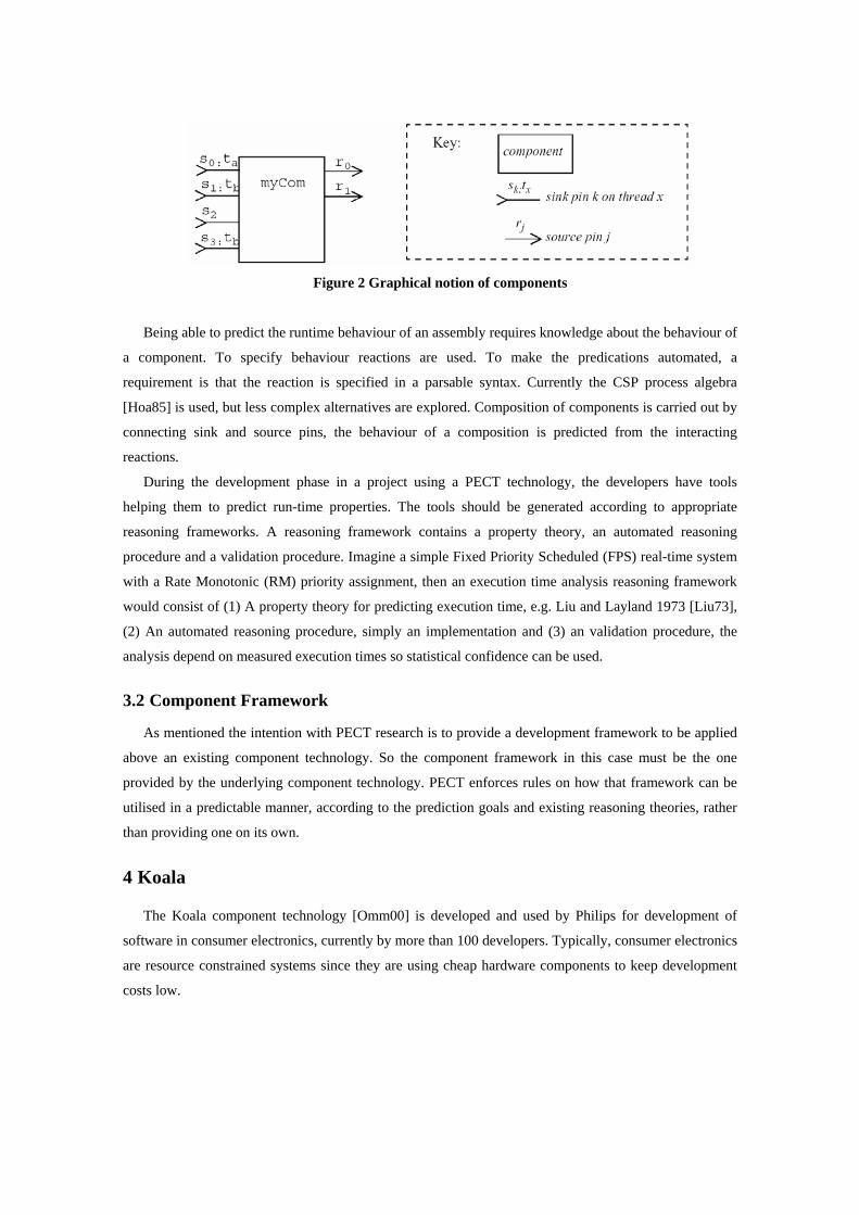
Figure 2 Graphical notion of components
Being able to predict the runtime behaviour of an assembly requires knowledge about the behaviour of
a component. To specify behaviour reactions are used. To make the predications automated, a
requirement is that the reaction is specified in a parsable syntax. Currently the CSP process algebra
[Hoa85] is used, but less complex alternatives are explored. Composition of components is carried out by
connecting sink and source pins, the behaviour of a composition is predicted from the interacting
reactions.
During the development phase in a project using a PECT technology, the developers have tools
helping them to predict run-time properties. The tools should be generated according to appropriate
reasoning frameworks. A reasoning framework contains a property theory, an automated reasoning
procedure and a validation procedure. Imagine a simple Fixed Priority Scheduled (FPS) real-time system
with a Rate Monotonic (RM) priority assignment, then an execution time analysis reasoning framework
would consist of (1) A property theory for predicting execution time, e.g. Liu and Layland 1973 [Liu73],
(2) An automated reasoning procedure, simply an implementation and (3) an validation procedure, the
analysis depend on measured execution times so statistical confidence can be used.
3.2 Component Framework
As mentioned the intention with PECT research is to provide a development framework to be applied
above an existing component technology. So the component framework in this case must be the one
provided by the underlying component technology. PECT enforces rules on how that framework can be
utilised in a predictable manner, according to the prediction goals and existing reasoning theories, rather
than providing one on its own.
4 Koala
The Koala component technology [Omm00] is developed and used by Philips for development of
software in consumer electronics, currently by more than 100 developers. Typically, consumer electronics
are resource constrained systems since they are using cheap hardware components to keep development
costs low.
4.1 Component Model
Koala is a light weight component model, tailored for Product Line Architectures. Currently no third
party components are integrated in Koala based products; all components are developed in house by
Phillips.
4.1.1 Component Definition
The Koala components are units of independent design, development and reuse, they can interact with
the environment or other components through explicit interfaces only. Because of this, no two basic
Koala components have any dependencies to each other. Furthermore the source code of koala
components are fully visible for the developers they are not binary or in any other intermediate format.
4.1.2 Component Interface
There are two types of interfaces in the Koala model, namely provides and requires interfaces. A
component may have multiple interfaces, which can be seen as a good way of handling evolution and
diversity.
Provides interfaces specify methods to access the component from the outside. The graphical notation
indicates that the init and tuner are provides interfaces by the direction of the arrows inside the connection
pins, while screen is of requires class. The bounding interface of the component is described by a
Component Description Language (CDL) to the upper right in the figure, and each interface is specified
in an Interface Definition Language (IDL) at the bottom in the figure. Both the IDL and CDL have C
influenced syntaxes.
4.1.3 Component composition
Components can be composed from other components and an application is called a configuration,
which consist of components with matching interfaces connected to each other. All requires interfaces of
a component must be bound to exactly one provides interface, while each provides interface can be bound
to zero or more requires interfaces. All communication in a configuration built with Koala components is
carried out utilising these interfaces, even calls to the operating system.
The bindings between components in Koala are static and resolved during compile time. Static
binding is suitable for resource constraint systems, it is efficient, predictable and 90% of the bindings are
known at design time and it is known which 10 % of the bindings that must remain flexible and also to
which extent [Crn02]. Koala has some features that allow for additional binding flexibility and easier
evolution. When two components are bound through a connection of their provides and requires
interfaces their functions are connected to each other on the basis of their name.
Koala allows that provides interfaces are wider than requires interfaces, the provides interface must
implement at least what the requires interface specifies but it may implement more than that. This feature
makes evolution of components easier, since it is possible to add new functionality into a component still
keeping compatibility with former versions.
When interfaces do not match, but a developer needs to connect two components anyway it is possible
to add glue code that forms a connector between the two components. Glue code can be written in C or in
a limited expression language within Koala.
The necessary degree of binding flexibility can be achieved with switches. A switch chooses between
provides interfaces offered by different components at run time, but is examined by the compiler at
compile time. The compiler tries to perform certain optimizations, such as reducing the switching
possibilities and remove unused connections and perhaps even components. A switch can also be reduced
to a straight binding by the compiler, if the switch is set to known position at run-time without being
touched.
4.2 Component Framework
The component framework is modelled in the Koala based design as a set of koala components. The
framework can be divided into two different layers, one computing layer which provides an API with a
higher abstraction to the computing hardware, and another layer that provides an API to the audio and
video hardware in the products. Components from an application can use arbitrary components from any
layer in the framework, and within the framework components from the audio video layer can use
components from the computing layer but not in the other direction.
The most basic functionality in the framework is located in the computing layer, which can be
compared to a very simple real-time kernel with priority driven pre-emptive scheduling. Another run-time
mechanism provided to keep the number of threads low, which in turn affect the memory utilization, is a
technique called thread sharing. This results in a form of late binding used for autonomous activities. The
implementation is through pumps, which are message queues with a function to process messages in the
context of a thread.
5 Robocop
Robocop is a component model developed in Eindhoven university. It is a follow-up, or a variant of,
the Koala model, which was developed by Philips research in Eindhoven. The aim of robocop is to define
an open component-based framework for the middleware layer in high volume embedded applications
[Jon03]. A component framework and component models in different abstractions form the core of the
Robocop architecture.
5.1 Component model
The Robocop project is a continuation, or a variant, of the koala component model. A Robocop
component is a set of models, each of which provides a particular type of information about the
component [Jon03]. An example of such a model is the non-functional model that includes modelling
timeliness, reliability, memory use, etc. Robocop aims to cover all aspects of a component-based
development process for embedded systems.
5.1.1 Component definition
A Robocop component is a set of models, each providing information about the component. The
models may be in different forms; human readable form, e.g., documentation or binary form. Other types
of models are functional model and non-functional model where the functional model describes the
functionality of the component, whereas the non-functional model describes timing, reliability, memory
usage etc. Each component is logically subdivided in services. Services in a robocop component are
comparable to public classes in an OO language. Services are instantiated in run-time and are logical
equivalent to objects in OO programming.
5.1.2 Component interface
A Robocop component may define several interfaces. The model distinguishes provided and required
interfaces, where provided ports are in-ports, and required ports are out-ports. The interfaces are separated
from the component implementation. This allows different components, supporting the same interface, to
be ”plugged in”, i.e., replaced, at any time. Tied to the provides interface is a set of resource parameters.
The resource consumption is defined per operation in the provides interface as a list of resources that are
claimed before execution, as well as the resources that are released when execution terminates. Each
operation defines a uses list that defines what operations are used from other interfaces. In addition, a
behaviour list is defined for each operation in the provides interface that defines a sequence of operation
it uses.
5.1.3 Component composition
Components can be composed from several models, and a composition of components is called an
application. Robocop has a framework that calculates system properties from compositions of
components, and the composition can be modelled by function composition. Robocop also supports third-
party binding, in a predictable assembly.
5.2 Component framework
The component framework in Robocop consists of several resource prediction models. The prediction
models use the component models and implementations if existing, to predict the amount of, e.g.,
memory that will be used. The framework predicts not only separate components, but also compositions.
During run-time a Robocop platform can execute a component that resides on the platform, or request a
component from a repository. This implies that the Robocop platform can dynamically bind the services
required by a component to the services provided by another component.
6 RUBUS component model
The Rubus Component Model runs on top of the Rubus Operating System [Rubus], and the
component model requires the Rubus configuration compiler. The Rubus OS is very small, and all
component and port configuration is resolved off-line by the Rubus configuration compiler. Rubus

component model supported by Rubus Visual Studio, the development environment shipped with the
Rubus RTOS is tailored for resource limited systems with real-time requirements. The purpose and main
objective with the model is to make it easier to reuse parts of systems and to maintain small differences
between similar products, which is essential when their customers maintain their product lines. Rubus has
a red and a blue part for hard and soft real-time respectively. The red part (red kernel) is used for time-
critical applications. The red-part is therefore time-triggered. The blue part on the other hand is event-
triggered, and used for less time-critical applications.
6.1 Component model
A basic software component consists of behaviour, a persistent state, a set of in-ports and out-ports
and an entry function. The thread of execution for a component is provided by a Rubus task. The
component technology is port-based and uses state-based communication. The communication between
time-critical components is unbuffered.
6.1.1 Component definition
A component consists of one or more tasks, which are the run-time entities executed by the operating
system. A task in turn is defined by a function pointer, data ports, and some attributes building the current
configuration of the task. A composite can also be identified, which is a logical composition of one or
more components. Components and composites are technically the same, but an encapsulation of
components is logically separated from an encapsulation of tasks by different notions. Figure 3, is a UML
meta-model showing the described items and relations. The abstractions above the task component and
composite is only design time structures.
ConfigurationPeriod TimeRelease TimeDeadlineWCETPrecedence Relation
In port
Out Port TaskEntry Function
11
Component
1..*1..*
Composite
1..*1..*
Porttype
0..*
0..*
0..*
0..*
0..*
0..*
Figure 3 A UML meta-model of the relations between different items
6.1.2 Component interface
The component interface in the Rubus component model is port based. A port is a shared variable.
Each component has in and out ports. The communication in the time-critical part (red part) is
unbuffered. In Rubus there are also non-functional interfaces, with which timing properties are defined.

The non-functional interfaces are specified by release-time, deadline, worst case execution times and a
period. No functional properties are defined by any interfaces. However, during system design it is
possible to define precedence relations, ordering and mutual exclusion.
6.1.3 Component composition
As in Figure 3, components and composites can be used as units of independent reuse, although the
run-time structures of components are a set of tasks. The tasks communicates with each others through
typed data ports, on activation a task reads the data on its in port, executes its function and finally writes
the result of the computation to its out port. From a design view the communication scheme yields a loose
temporal coupling between tasks. A loose coupling in time is realized, since send and receive actions may
take place asynchronously completely independent on each others. On the other hand the scheme creates
a hard coupling in space since the sender and receiver of a data have to be specified during design time,
when connecting ports between tasks.
The Configuration Compiler (CC), is a tool used to verify and construct scheduling schemes for the
Rubus operating system. Input to the tool is the design described in a formal specification language and
the specification of the available CPU capacity. If the CPU capacity is enough the tool generates a
schedule, for the Rubus operating system which specifies when each task shall be executed. The
scheduling algorithm in CC is based on a heuristic tree search strategy, with interrupt handling [San98].
CC is by default configured to not allow any pre-emption, which means that a task cannot be pre-empted
by another. However, pre-emption can be allowed, and when pre-emption is allowed, access to shared
resources are resolved by CC and the formal specification language has a way to express this shared
access between tasks.
This in turn means that any protection of shared resources becomes unnecessary, since tasks are
separated in time.
6.2 Component framework
The Rubus component model is developed on top of the Rubus Real-Time Operating System. Rubus
is a real-time operating system with support for both static scheduling and pre-emptive fixed priority
scheduling. The static and pre-emptive fixed priority schedulers are referred to as the red and blue parts
of Rubus respectively. The red part only handles hard, static real-time, whilst the blue part only handles
soft real-time. Finally, there is also a green part of Rubus, which is an interrupt handler kernel. It has the
highest priority, and distributes and routes the interrupts.
The red part of Rubus always has higher priority than the blue part. Therefore, the red part is used for
time critical operations (firm and hard real-time), since it is easier to verify timing properties of the red
part. The blue part of Rubus is usually used for more dynamic properties, and soft real-time. The green
part always handles all interrupts, and has the highest priority in the system.

7 Port Based Objects
Port Based Objects (PBO) [Ste97] combines object oriented design, with port automaton theory. PBO
was developed as a part of the Chimera RTOS project at the Advanced Manipulators Laboratory at
Carnegie Mellon University. Together with Chimera, PBO forms a framework aimed for development of
sensor-based control systems, with specialization in reconfigurable robotics applications.
7.1 Component model
A pronounced design goal for a system based on PBO is to minimize communication and
synchronization, thus facilitating reuse. PBO implements analysis for timeliness and facilitates
behavioural models to ensure predictable communication and behaviour. However, there are few
additional analysis properties in the model. The communication and computation model is based on the
pipes-and-filters model, to support distribution in multiprocessor systems the connections are
implemented as global variables.
7.1.1 Component definition
A PBO is also called a control module, and is a software component. A PBO is defined as an object
with various ports for real-time communication. As any object it has a state, but unlike ordinary objects
the methods are hidden, it is only the ports that are visible from the outside. To be strict you could say
that a PBO is neither an object nor a true software component, but with a more practical interpretation of
definitions it can be depicted as both.
7.1.2 Component interface
The ports of an object may be classified as input-, output- or resource ports. Input and output ports are
used for communication between collaborating objects, while resource ports are aimed for
communication with sensors, actuators or other external devices or sub-systems. A PBO may have an
arbitrary number of ports of each class. A PBO is drawn as a round-corner rectangle, with its input- and
output ports are drawn as arrows entering/leaving the sides of the rectangle. To the top and bottom we
have configuration constants and resource ports marked as double directed arrows respectively.
7.1.3 Component composition
When building an application of PBOs, all existing ports must be connected for the configuration to
be valid. The state variable communication between PBOs are created by the user by connecting input
and output ports, the details are hidden and taken care of by the framework. The framework builds tables
with state variables, every I/O port and configuration constant is stored as a state variable in shared
memory. Every PBO is served through a local table with its own subset of state variables, there is no
synchronization needed for read and writes to the local table since it is only accessed by one PBO, which
can thus execute independently of other PBOs. Consistency between the local and global table is
maintained by a simple execution semantic. State variables corresponding to input ports are updated just

before executing a PBO, and are copied from the global table to the local table. State variables
corresponding to output ports are updated after the execution of a PBO, and are copied in the opposite
direction from the local table to the global table, so during its execution a PBO can write to its output
ports at any time.
The port-automaton theory provides methods for modelling transfer functions for each PBO,
describing the output response for a given input. A closed or open loop system can be analysed by
applying the transfer functions according to the connection scheme. Timing analysis based on each PBOs
Worst Case Execution Time (WCET) and analysis of the state variable communication are also available
both for single and multiprocessor environments. In the bottom of the figure, the resource ports are drawn
and connected to various sensors, actuators and sub-systems. The PBOs are connected to each other by in
and out ports to the sides of them, forming the look of a classical closed loop system familiar for control
engineers.
7.2 Component Framework
The PBO model is aimed for execution on the Chimera RTOS [Kho92]. Chimera is a real-time
operating system with multiprocessor support designed especially to support the development of software
for robotic and automation systems. The code is compiled and linked with an ordinary SUN C compiler
and linker.
Chimera provides typical RTOS kernel task management features, such as creating, suspending,
restarting, pre-empting and scheduling. The kernel schedules the tasks using virtual timers, all based on a
hardware timer. Chimera supports both static and dynamic scheduling of real-time tasks. The default
scheduler supports the rate monotonic scheduling algorithm (static scheduling), the earliest-deadline-first
scheduling algorithm (dynamic scheduling) and the maximum-urgency-first scheduling algorithm (static
and dynamic scheduling).
A task can communicate or synchronize with any other task through shared memory, high-
performance semaphores or user signals. Above this many different types of inter-process communication
and synchronization mechanisms are built in as layers, in purpose to simplifying the development of
complex applications. In particular for applications built with PBO it is the state variable mechanism
described in the composition chapter that is used as a mapping for the data ports.
8 PECOS
PECOS (PErvasive COmponent Systems) [Nie02] [Pecos][Win02] is a collaborative project between
ABB Corporate Research Centre and academia. The goal for the PECOS project is to enable component-
based technology for embedded systems, especially for field devices. The project tries to consider non-
functional properties very thoroughly in order to enable assessment of the properties during construction
time.
8.1 Component model
As many other component technologies PECOS separates the development of the application and the
components. The component model in PECOS is aimed to express, functional interfaces, e.g., procedural
interfaces and non-functional properties and constraints. The PECOS model has an execution model that
describes the behaviour of a field device. The execution model deals with synchronisation and timing
related issues, and it uses Petri-Nets [Srg98] to model concurrent activities like component compositions,
scheduling of components, and synchronisation of shared ports [Nie02]. Debugging can be performed
using COTS debugging and monitoring tools.
8.1.1 Component definition
A component in the PECOS model is a computational element with a name, a number of property
bundles and ports, and a defined behaviour. The ports of the component represent data that may be shared
with other components. The behaviour of a component consists of a procedure that reads and writes data
available at its ports.
The formal definition of components in PECOS is realized with a language called CoCo, developed
within the PECOS project. CoCo is intended to be used for both the specification of the components and
the specification of field device applications, built as compositions. CoCo supports the basic elements
components, ports and properties, and in addition for composite components instances and connectors.
Properties are the characteristics of a component and are represented in CoCo with a tag and a value,
example of properties is period time and execution time.
The type of a component can be of one of the three passive, active or event. Passive components are
as the name reveals a component without a thread of control. They are scheduled by their closest active
ancestor. Active components are the opposite of passive components, and have their own thread of
control. Event components are components that are triggered by an event and have a thread of control.
They are often used to model hardware that frequently emits events.
Figure 4, shows a UML Meta model of a component, defining relations between different types of
component and properties characterising a component.

Figure 4 UML diagram showing the structure of a component [are01]
8.1.2 Component Interface
The interface is as indicated port based. A port is a shared variable that allows a component to
communicate with other components. Connected ports represent the same shared variable. A port
specifies a name, a type, a range (minimum and maximum), and a direction (in, out or inout). The
direction indicates if the component reads, writes or does both on a specific port.
Ports can only be connected if they have the same type, and their directions are complementary. Thus,
an out port can only connect to an in port. Internal ports (within a composite component) however, can be
connected to an external port with the same direction, e.g., an external in port can be connected to an
internal in port.
8.1.3 Component Composition
Components are categorized into leaf components and composite components. A leaf component is a
“black box” component not further defined by the model, but rather directly implemented in the host
programming language.
A composite component on the other hand contains a number of sub-components connected with the
internal ports. The external ports of the composite component are connected to suitable internal ports. The
sub-components are not visible outside the composite component. The software can be modelled as a
component hierarchy, i.e., a tree of components with a single active composite component at its root.
In Figure 5, a composite component is built from a couple of sub components. The sub component
FQD is an event component while ModBus is an active component, the component ProcessApplication
on the other hand is a passive component. There are a set of internal ports between the components, and
one external port setPoint.

Figure 5 A composite component [are02]
8.2 Component Framework
There is no special run-time environment developed in the PECOS project. Instead there are
requirements on platform independence, or at least portability. In [Mul01] it is claimed that source level
portability is sufficient. This requires some agreement on the language (e.g. ANSI C or C++). The run-
time environment used in this case is any arbitrary RTOS.
9 IEC 61131
Because of the prior problems with the lack of standards for PLCs (Programmable Logic Controllers),
IEC instituted a standard in 1993. The name of the standard is “IEC 61131: Programmable Controllers”
[Iec92], and part 3 of the document refers to programming languages. At that time several well
established techniques for programming PLCs existed, so the authors of the standard found it necessary to
include several different programming methods. The standard describes three graphical and two text
based languages, it concentrates on the syntax and leave the semantics less definitive.
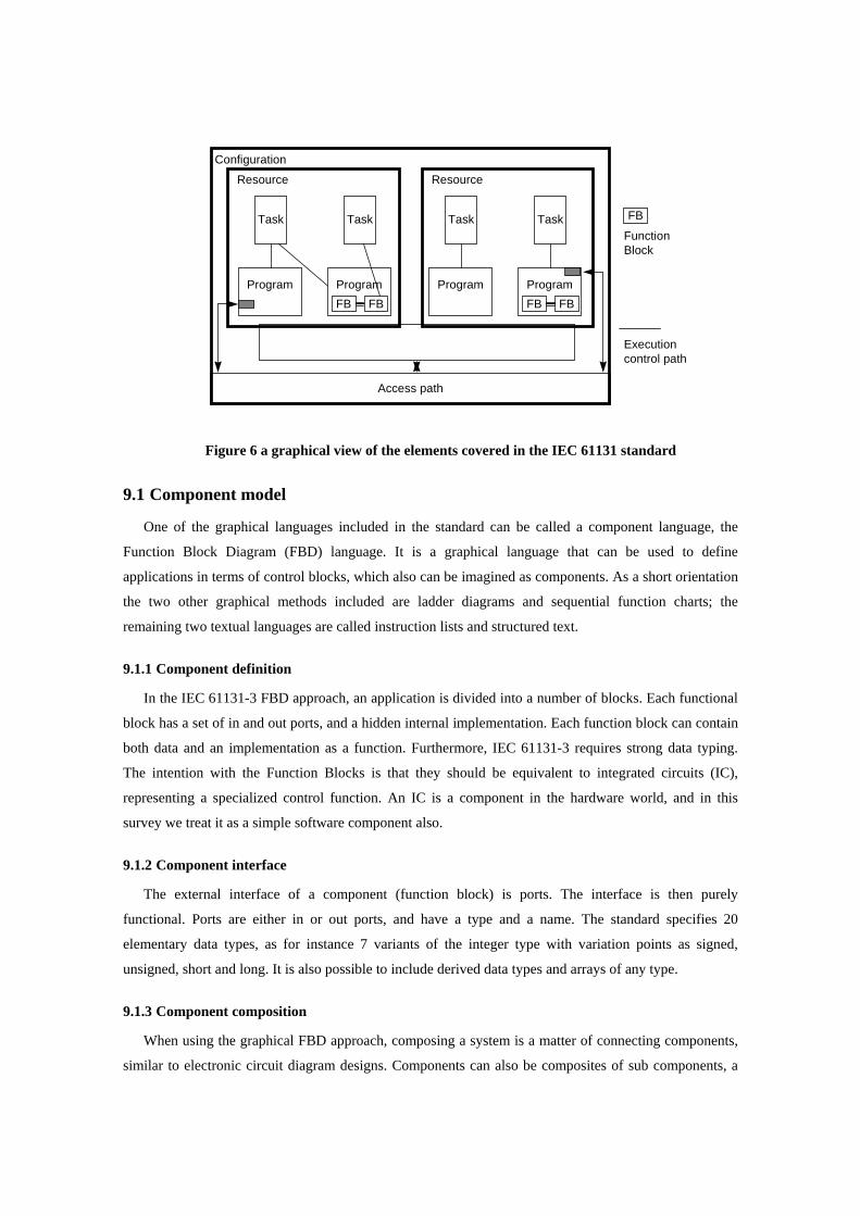
In Figure 6, the principles of the standard are visualized. The standard covers the construction of
whole systems. At the top level, the configuration defines the entire system. Within a configuration one or
more resources are defined. A resource is a processing unit, which contains one or more Tasks. Tasks in
turn are defined by any of the programming languages included in the standard.
Access path
Executioncontrol path
FBTask
Program ProgramFB FB
Task
Program
Task
ProgramFB FB
Task
Resource Resource
Configuration
FunctionBlock
Figure 6 a graphical view of the elements covered in the IEC 61131 standard
9.1 Component model
One of the graphical languages included in the standard can be called a component language, the
Function Block Diagram (FBD) language. It is a graphical language that can be used to define
applications in terms of control blocks, which also can be imagined as components. As a short orientation
the two other graphical methods included are ladder diagrams and sequential function charts; the
remaining two textual languages are called instruction lists and structured text.
9.1.1 Component definition
In the IEC 61131-3 FBD approach, an application is divided into a number of blocks. Each functional
block has a set of in and out ports, and a hidden internal implementation. Each function block can contain
both data and an implementation as a function. Furthermore, IEC 61131-3 requires strong data typing.
The intention with the Function Blocks is that they should be equivalent to integrated circuits (IC),
representing a specialized control function. An IC is a component in the hardware world, and in this
survey we treat it as a simple software component also.
9.1.2 Component interface
The external interface of a component (function block) is ports. The interface is then purely
functional. Ports are either in or out ports, and have a type and a name. The standard specifies 20
elementary data types, as for instance 7 variants of the integer type with variation points as signed,
unsigned, short and long. It is also possible to include derived data types and arrays of any type.
9.1.3 Component composition
When using the graphical FBD approach, composing a system is a matter of connecting components,
similar to electronic circuit diagram designs. Components can also be composites of sub components, a

picture derived from the standard visualizing a composed component declaration with external interface
and body is shown in Figure 7. The figure consists of two parts the external interface definition in the
upper half and the body with interconnected sub components in the lower part. Notice that ports inside the
component in the upper part of the figure has the same name as the boundary ports in the lower part of the
figure, when specifying the internal structure.
EXAMPLE IN OUTDB_TIME ET_OFF
FUNCTION_BLOCK (** External Interface **)
(** Function Block Body **)
A X Y
BOOL TIME
BOOL TIME
B V ZT
A X Y O
IN
DB_TIME
OUT
ET_OFF
END_FUNCTION_BLOCK
Figure 7 graphical function block declaration
9.2 Component framework
There is no special construction that can be treated as a component framework defined by the
standard, since components are mapped to ordinary tasks before runtime. It is the operating system that is
responsible for task execution, it is not much mentioned about the operating system but part 1 of the
standard (IEC 61131-1, with general information) defines the some restrictions like no pre-emption of
tasks.
10 CORBA / CCM (CORBA Component Model)
The Common Object Request Broker Architecture (CORBA) [Omg01] is a standard that provides a set
of rules for writing platform independent applications. The CORBA standard is developed by the Object
Management Group (OMG). CORBA permits the developer to hide much of the low-level complexity,
and offers a platform independent interface. However, a major drawback is that CORBA implementations
often results in both bulky and computation intensive systems, and therefore too large to fit devices with
limited resources.
In order to be able to use CORBA within smaller more resource constrained systems OMG has
suggested a subset of CORBA, called minimum CORBA. Minimum CORBA omits many of the resource
intensive features that are not typically essential to a basic CORBA implementation. Most dynamic
features have been omitted from the minimum CORBA standard since resource constrained systems tend
to make commitments at design-time rather than at run-time. For instance all dynamic features, such as
dynamic invocation interface, dynamic skeleton interface etc., have been omitted from the minimum
CORBA standard. However, for full compatibility with the CORBA standard, the minimum CORBA
supports full IDL (Interface Definition Language).
Another approach taken by OMG to deal with the expression and enforcement of real-time constraints
on end-to-end execution is the Real-Time CORBA. In Real-Time CORBA the ORB is extended with real-
time capabilities. Examples of Real-Time CORBA implementations are TAO [Sch97] and NRaD/URI
[Wol97].
Whilst minimum CORBA is a variant of CORBA with a lot of functionality omitted, the Real-Time
CORBA is a set of CORBA add-ons to be able to handle clock synchronization, bounded execution times
etc. It could still be stated that Real-Time CORBA is not really suited for resource constrained systems
with limited calculation capabilities and huge requirement of memory resources.
The traditional CORBA object model has several limitations. Some of these are no standard way to
deploy object implementations, limited standard support for common CORBA server programming
patterns, limited extension of functionality, no defined availability and no standard object lifecycle.
In 1999 the Object Management Group suggested a component model for CORBA, namely the
CORBA Component Model (CCM). CCM is a server side component model tat is used to assemble and
deploy multilingual components. The CCM is supposed to cover the limitations of the traditional CORBA
object model.
CCM extend the CORBA object model by defining features and services that enable application
developers to implement, mange, configure and deploy components that integrate commonly used
CORBA services, such as transaction, security, persistent state and event notification. In addition the
CCM allows a better software reuse for servers and provides a greater flexibility for dynamic
configuration of CORBA applications.
10.1 Component model It is difficult to define a component model within the scope of standard CORBA since applications do
not have to follow any given model. However, the Interface Definition Language (IDL) could be seen as
a loose component model. The IDL defines one way only of access of an object, at least between the
client and server side objects.
CCM components are the basic building blocks of a CCM system. CCM standardizes the component
development cycle by utilizing CORBA as its middleware infrastructure. The components are
implemented by tools provided by CCM providers. And the components are packed in a container, such
as a shared library (DLL), or a Jar-file. A deployment mechanism also supplied by CCM providers is used
to deploy the component in a component server that hosts component implementations. The component
executes in the component server and is available to client requests.
10.1.1 Component definition
According to the given model of standard CORBA as a component, it is defined by an Interface
Definition Language. The IDL is a C++ like language that defines the interfaces related to target objects.
It is not a programming language like C++ or Java in the sense that objects and applications cannot be
implemented in IDL. The latter merely allows object interfaces to be defined in a fashion that is
independent of any particular programming language. This is vital to the CORBA goal of supporting
heterogeneous systems and integrating separately developed applications.
CCM components are defined by a declarative language called Component Implementation Definition
Language (CIDL). CIDL describes the implementation and persistent state of components and
component homes. Implementations generated by a CIDL compiler are called executors. Executors
contain auto-generated implementations and provide hooks that allow developers to add custom
behaviour.
10.1.2 Component Interface
Standard CORBA interfaces are stated and designed by the user at design-time. These are the
interfaces between the server and client objects. There are several levels of interfaces in CORBA. There
are actual interfaces and conceptual interfaces. The actual interfaces are between the application and the
ORB. However, these interfaces are automatically generated with tools and the Interface Definition
Language (IDL).
CCM Component provides four types of mechanisms called ports to interact with other CORBA
artefacts. These port mechanisms specify the required interface that a component exposes to clients. The
port mechanisms are
Facets: These are the interfaces that a component provides. Facets allow a component to expose
different views to its clients by providing different interfaces.
Receptacles: The receptacles are the object references to the instances of the other components it
uses. In CCM these references are object connections and the port name of these connections are called
receptacles.
Event source/sink: These are ports used by components to interact by monitoring asynchronous
events.
Attributes: The attributes are extra-functional properties that can be used by configuration tools to
preset configuration values on a component.
10.1.3 Component Composition
Because standard CORBA components reside on different nodes, client-side and server-side,
traditional composition may not be possible. However, on a higher level, the composition of these
components could be precedence at design time.
A CCM component can compose together unrelated interfaces. Composed components communicate
with each other through the receptacles interface. There are no means of composing and encapsulating
several components into one component entity, but they rather communicate through the ports.
10.2 Component frameworks
Both standard CORBA and CCM run-time frameworks are the Object Request Broker (ORB), which
is a middleware technology that manages communication and data exchange between objects. The ORB
promotes interoperability of distributed object systems because it enables users to build systems by
connecting objects from different vendors that communicate via the ORB, in other words the ORB
promotes reusability. The ORB locates a server object implementation during run-time and establishes
connections to the server and interprets object references.
11 Summary
In this report we have compared some existing component technologies for embedded systems with
respect to the component model and framework.
However, it should be noted that PECT is not really a component technology, but more of an analysis
framework, and CORBA/CCM is a high level heavy weight component technology that can be used to
build large distributed systems. The other technologies, are used for embedded, and in some cases very
resource constrained systems. The comparison between, e.g., CORBA/CCM and PECOS is only in the
interest to show the difference between a large component technology and smaller technology, and also to
investigate if CCM or Minimum CORBA seems to be suitable for making smaller systems as well.
Below follows a short conclusion of all described component models with respect to their suitability
for embedded systems.
11.1 PECT
PECT is an abstract technology that requires an existing underlying component technology. For
instance, how testable and debugable a system is depends highly on the technical solutions in the
underlying run-time system. Resource consumption, computational model, reusability, maintainability,
black- or white-box components, static- or dynamic-configuration are also not possible to determine
without knowledge of the underlying component technology. Worth to notice is that although reusability
and maintainability is not directly addressed by PECT, the analysability increases these abilities.
Since PECT is not a component technology but rather a framework that can be applied to any
component technology, the suitability for embedded systems is highly dependent on the underlying
component technology. With respect to analysis PECT is highly suitable for all time critical systems.
11.2 Koala
Koala does not support analysis of run-time properties. Research has presented how properties like
memory usage can be analyzed, but the thread pumps used in Koala might cause some problems to apply

existing timing analysis theories. Koala has no explicit support for testing and debugging, but they use
source code components, and a simple interaction model. Furthermore, Koala is implemented for a
specific operating system. A specific compiler is used, which routes all interaction to the operating system
through Koala connectors.
For systems with requirements on analyzability and timeliness the Koala model is not highly suitable
due to the lack of extra-functional properties. Although Koala has shown, through industrial use, to be
highly efficient and suitable for some embedded system, it is probably not suited for, e.g., safety critical
systems.
11.3 Robocop
Robocop is a variant of the Koala model. Robocop supports, unlike Koala, several extra-functional
properties such as timeliness, performance, reliability, availability, safety and security. Robocop supplies
a set of tools and methods for calculating extra-functional properties on compositions (applications). It
also allows for third-party bindings. Robocop is suitable for resource constrained embedded systems.
However, the model is based on resource predictions, which does not give 100% guarantees unlike formal
methods. Therefore, it can not be considered suitable for safety-critical systems.
11.4 RUBUS
The Rubus Component Model runs on top of the Rubus Operating System [Rubus], and the
component model requires the Rubus configuration compiler. There is support for different hardware
platforms but the Rubus component model is tightly coupled to the Rubus operating system. The Rubus
OS is very small, and all component and port configuration is resolved off-line by the Rubus
configuration compiler. Non-functional properties can be analysed since the component technology is
statically configured, but timing analysis is the only analysable properties implemented.
Rubus component model has many years of industrial use and has shown to be highly useable for
some embedded systems. For systems that require more analyzability than timeliness and schedulability
the Rubus model may be insufficient.
11.5 PBO
PBO is a simple and intuitive model that is highly understandable, both at system level and within the
components themselves. The low coupling between the objects makes it easy to modify or replace a
single component. PBO uses port-automaton theory that provides an algebraic model of the system that is
suitable for control systems. It is built with active and independent objects that are connected with the
pipes-and-filters model. Due to the low coupling between objects through simple communication and
synchronisation the objects can be considered to be highly reusable. PBO implements analysis for
timeliness and facilitates behavioural models to ensure predictable behaviour. There are few additional
analysis properties in the model. The communication and computation model is based on the pipes-and-
filters model. PBO is tightly coupled to the chimera OS and components are mapped to individual

processes. For these reasons PBO is not highly suitable for resource constrains systems. PBO also lack in
analysability for systems that require analysability other than schedulability and timeliness.
11.6 PECOS
PECOS is designed for reactive embedded systems that gather and analyze data via sensor and react
by controlling actuators. The PECOS Component technology uses layered software architecture and
components are connected with the pipes-and-filters model. PECOS is a component technology that is
highly analyzable, but not very expressive. It is very efficient for small very resource constrained
embedded systems. For larger systems PECOS is not highly suited, due to its lack of expressing more
complicated systems.
11.7 IEC61131-3
IEC61131-3 is a component model that is developed for programming PLCs. It is port-based and very
resource constrained. There are no extra-functional properties in IEC61131-3 which makes the
analyzability low. However, the technology is quite easy to understand and is highly suitable for
describing finite automates. For these reasons IEC61131-3 is often used in automation industry. However,
due to the lack of analyzability, IEC61131-3 cannot be considered suitable for safety-critical or real-time
systems.
11.8 CORBA/CCM
While CORBA is portable, and powerful, it is very run-time demanding and e.g. bindings are
performed during run-time. Because of the run-time decisions, CORBA is not very deterministic or
analysable. There are no extra-functional properties or any specification of interface behaviour. A CCM
component can have strong, undocumented, assumptions on its use and context. All these things together
make reuse virtually impossible in embedded systems. The maintainability is also suffering from the lack
of clearly specified interfaces.
12 References
[Are01] G. Arévalo, S. Ducasee, O. Nierstraz, R: Wuyts; Field-Device Component Model-V, Deliverable D2.2.8-5, IST1999-20398 PECOS, University of Bern, October 2001
[Are02] G. Arévalo, S. Ducasee, P. Liang, O. Nierstraz, R: Wuyts; Verifying timing, memory consumption and scheduling of components, Deliverable D2.2.6-3, IST1999-20398 PECOS, University of Bern, July 2002
[Bac00] F. Bachmann, L. Bass, C. Buhman, S. Comella-Dorda, F. Long, J. Robert, R. Seacord, and K. Wallnau; Technical Concepts of Component-Based Software Engineering, Volume II. Technical Report CMU/SEI-2000-TR-008, Software Engineering Institute, Carnegie-Mellon University, May 2000
[Con01] M. Connolly, CORBA Middleware for a Palm Operating System, Master of Science dissertation thesis, University of Dublin, September 2001.
[Crn02] I. Crnkovic and M. Larsson. Building Reliable Component-Based Software Systems. ArtechHouse, 2002.
[Hoa85] C. A. R. Hoare. Communicating Sequential Processes. Prentice Hall, 1985. [Iec92] International Standard IEC 1131. Programmable controllers, 1992. [Kho92] P. K. Khosla et al., The Chimera II Real-Time Operating System for Advanced Sensor-Based Control
Applications, IEEE Transactions on Systems, Man and Cybernetics, 1992.
[Liu73] C. I. Liu and J. W. Layland. Scheduling Algorithms for Multiprogramming in a Hard-Real-Time Environment. Journal of the ACM, 20(1), 1973.
[Mul01] P. Müller, C. Zeidler, C. Stich, A. Stelter. PECOS — Pervasive Component Systems, Workshop on Open Source Technologie in der Automatisierungstechnik, GMA Kongress 2001.
[Nie02] O. Nierstrasz, G. Arévalo, S. Ducasse, R. Wuyts, A. Black, P. Müller, C. Zeidler, T. Genssler, R. van den Born, A Component Model for Field Devices Proceedings of the First International IFIP/ACM Working Conference on Component Deployment, Germany, June 2002.
[Omg01] OMG. The common object request broker: Architecture and specification. OMG Formal Documatation (formal/01-02-10), February 2001.
[Omm00] R. van Ommering, F. van der Linden, and J. Kramer. The Koala component model for consumer electronics software. IEEE Computer, 33(3):78–85, March 2000.
[Pecos] T. Genssler, A. Christoph, B. Schuls, M. Winter, et al.; PECOS in a Nutshell, PECOS project homepage: http://www.pecos-project.org
[Rubus] Rubus OS Reference Manual, General Concepts, Arcticus Systems, Home Page: http://www.arcticus.se
[San98] K. Sandström, C. Norström, G. Fohler; Handling Interrupts with Static Scheduling in an Automotive Vehicle Control System, In Proceedings of the fifth International Conferance on Real-Time Computing Systems and Applications,pages 158-165, October 1998. IEEE Computer Society.
[Sch97] D.C. Schmidt, D.L. Levine, and S. Mungee. The Design of the tao real-time object request broker. Computer Communications Journal, Summer 1997
[Srg98] M. Sgroi. Quasi-Static Scheduling of Embedded Software Using Free-Choice Petri Nets (M.S. Dissertation), University of California at Berkeley, May 1998
[Ste97] D. B. Stewart, R. A. Volpe, P. K. Khosla. Design of Dynamically Reconfigurable Real-Time Software Using Port-Based Objects, IEEE Transactions on Software Engineering, December 1997, pages 759-776.
[Wal03] K. C. Wallnau. Volume III: A Technology for Predictable Assembly from Certifiable Components, Technical report, Software Engineering Institute, Carnegie Mellon University, April 2003, Pittsburgh, USA.
[Win02] M Winter, T Genssler, et al.; Components for Embedded Software – The Pecos Approach; Second InternationalWorkshop on Composition Languages, In conjunction with 16th European Conference on Object-OrientedProgramming (ECOOP) Málaga, Spain, June 11, 2002
[Wol97] V.F Wolfe, L.C. DiPippo, R. Ginis, M. Squadrito, S.Wohlever, I. Zykh, and R. Johnston. Expressing and Enforcing timing constraints in a dynamic real-time corba system. Technical report, University of Rhode Island, June 1997.
[Jon03] M. de Jonge, J. Muskens, M. Chaudron; Scenario-Based Prediction of Run-Time Resource Consumption in Component –Based Software Systems, In proceedings of the 6th ICSE Workshop on Component-Based Software Engineering. Portland, Oregon, USA. May 3, 2003.


![Component-Based Vehicular Distributed Embedded Systems ... · embedded systems in the vehicular domain. 1) Rubus Component Model (RCM) and Rubus-ICE: Rubus [28] is a collection of](https://img.pdfslide.us/doc/110x75/5f4e56e700e19031d45cfd3b/component-based-vehicular-distributed-embedded-systems-embedded-systems-in-the.jpg)