Embed Size (px)
Citation preview
inventions
Article
A Rolling Electrical Generator Design and Model forOcean Wave Energy Conversion
Praveen Damacharla 1,* and Ali Jamali Fard 2
1 R&D Department, KineticAI Inc., Crown Point, IN 46307, USA2 Electrical Engineering, Amirkabir University of Technology, Tehran 1591634311, Iran; [email protected]* Correspondence: [email protected]; Tel.: +1-419-450-0357
Received: 12 November 2019; Accepted: 6 January 2020; Published: 10 January 2020�����������������
Abstract: Wave and tidal energies are some of the most prominent potential sources of renewableenergy. Presently, these energy sources are not being utilized to their maximum extent. In this paper,we present a new conversion mechanism with an innovative electrical energy converter design thatenables the use of wave energy to its maximum potential. The conventional wave energy convertercomprises two stages of conversion (kinetic to mechanical and mechanical to electrical), imposingtransformation loss that reduces the overall system efficiency. Additionally, the architecture andoperational norms are dependent on the availability of shoreline areas, and the convertor is notsuitable for all ocean weather conditions. To solve these problems, we have developed a wave energyconversion system that integrates the two stages of power with the minimum number of movingparts. This results in significant reduction of transformation losses that otherwise occur in the process.This paper presents an innovative idea of designing a DC generator that reduces the hierarchy ofpower conversion levels involved to improve the efficiency. The back and forth motion of the machinemeans it operates in a two-quadrant generation mode. The machine was constructed as a squarebox model with windings placed on both the top and bottom stator plates, and the rotor consistedof a field winding placed between these plates with two axes of operation. The electromagneticfield (EMF) induced in the stator plates is due to the resulting flux cutting, which is generated by arolling object (rotor) in between them. A finite element analysis (FEA) of the machine is also listedto validate the flux linkage and operational efficiency. Additionally, a generator is fabricated to thepredetermined design criteria as a proof of concept and the corresponding results are posted in thepaper. Additionally, we present the material and cost limitations of this invention and outline somepossible future directions.
Keywords: electrical generator; renewable energy; wave energy; finite element analysis (FEA)
1. Introduction
With the increasing concerns related to energy demand and environment problems, wavepower generation is gaining more traction than ever [1,2]. Ocean waves are one of the potentialrenewable energy resources available, with an estimated energy to be 17,500 TWh/year worldwide [2].The estimates indicate that the annual wave energy potential of the U.S. coastline alone is around2640 TWh/year [3]. The theoretical potential for a coastline works out to be approximately 60,000 MW,and it is possible to harness 40 MW of power per km of coastline in a low wave region (for example,one meter in height). As for high waves (5 m height), the power potential increases to as muchas 1000 MW per km. According to the world wave energy chart released by World Energy Council,the Bay of Bengal and the Arabian ocean have a combined potential of 800 TWh/year per meter, andthe Indian Ocean has a potential of nearly 1340 TWh/year [2,3].
Inventions 2020, 5, 3; doi:10.3390/inventions5010003 www.mdpi.com/journal/inventions
Inventions 2020, 5, 3 2 of 15
There are many methods and designs employed to harness wave energy worldwide.The TAPCHAN [2] wave energy converter and the Islay wave energy converter are two of thefew successfully working models, and are of the oscillating water column (OWC) type. On the otherhand, the Duck, Clam, and Pelamis converters from the United Kingdom are of the floating type [2].The Pelamis converter is one of the working prototypes, with a capacity of 750 KW, 150 m in length,3.5 m in diameter, and composed of five modular sectors [2].
Many of the existing models follow a two-stage power conversion topology to generate electricpower (stage 1: kinetic to rotational; stage 2: rotational to electrical) [4,5]. As this WEC topologyhas the drawbacks of low speed and poor stability, a gearbox could be utilized to mitigate theseproblems between WEC and the generator. However, a gearbox would make the drive system bulkyand inefficient, and would also increase the investment and maintenance costs. In order to avoidusing a gearbox, generators with features of low speed and high torque density and efficiency arerequired [2,6–8]. The design provided in this paper uses wave kinetic energy as a prime mover, whichimplies one less stage of energy conversion to generate electrical power [9,10]. The generator in thedesign floats on water and is capable of harnessing electrical energy in an economical way, even fromlow energetic waves. This type configuration is more suitable for peninsulas in U.S. coastal states,India, and a few islands [11].
In the following sections, we discuss operating principles, design, simulation, and testing of theproposed innovation. Sections 2 and 3 elaborate the operating principle of the generator and the designprocedure, followed by discussion. Simulation analysis of the generator and the corresponding resultsare discussed in Sections 4 and 5. Finally, Section 6 concludes the paper with a discussion on the proofof concept.
2. Operating Principles
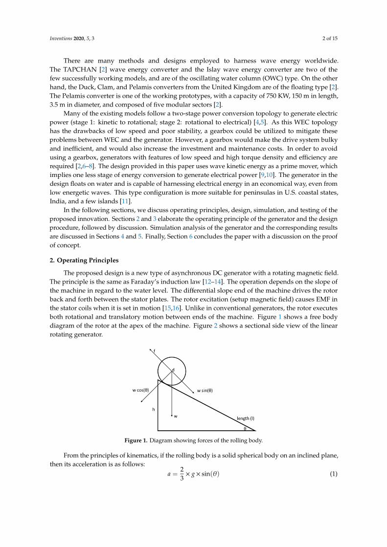
The proposed design is a new type of asynchronous DC generator with a rotating magnetic field.The principle is the same as Faraday’s induction law [12–14]. The operation depends on the slope ofthe machine in regard to the water level. The differential slope end of the machine drives the rotorback and forth between the stator plates. The rotor excitation (setup magnetic field) causes EMF inthe stator coils when it is set in motion [15,16]. Unlike in conventional generators, the rotor executesboth rotational and translatory motion between ends of the machine. Figure 1 shows a free bodydiagram of the rotor at the apex of the machine. Figure 2 shows a sectional side view of the linearrotating generator.
Inventions 2020, 5, x 2 of 15
There are many methods and designs employed to harness wave energy worldwide. The
TAPCHAN [2] wave energy converter and the Islay wave energy converter are two of the few
successfully working models, and are of the oscillating water column (OWC) type. On the other hand,
the Duck, Clam, and Pelamis converters from the United Kingdom are of the floating type [2]. The
Pelamis converter is one of the working prototypes, with a capacity of 750 KW, 150 m in length, 3.5
m in diameter, and composed of five modular sectors [2].
Many of the existing models follow a two-stage power conversion topology to generate electric
power (stage 1: kinetic to rotational; stage 2: rotational to electrical) [4,5]. As this WEC topology has the
drawbacks of low speed and poor stability, a gearbox could be utilized to mitigate these problems
between WEC and the generator. However, a gearbox would make the drive system bulky and
inefficient, and would also increase the investment and maintenance costs. In order to avoid using a
gearbox, generators with features of low speed and high torque density and efficiency are required [2,6–
8]. The design provided in this paper uses wave kinetic energy as a prime mover, which implies one
less stage of energy conversion to generate electrical power [9,10]. The generator in the design floats on
water and is capable of harnessing electrical energy in an economical way, even from low energetic
waves. This type configuration is more suitable for peninsulas in U.S. coastal states, India, and a few
islands [11].
In the following sections, we discuss operating principles, design, simulation, and testing of the
proposed innovation. Sections 2 and 3 elaborate the operating principle of the generator and the
design procedure, followed by discussion. Simulation analysis of the generator and the
corresponding results are discussed in Sections 4 and 5. Finally, Section 6 concludes the paper with a
discussion on the proof of concept.
2. Operating Principles
The proposed design is a new type of asynchronous DC generator with a rotating magnetic field.
The principle is the same as Faraday’s induction law [12–14]. The operation depends on the slope of
the machine in regard to the water level. The differential slope end of the machine drives the rotor
back and forth between the stator plates. The rotor excitation (setup magnetic field) causes EMF in
the stator coils when it is set in motion [15,16]. Unlike in conventional generators, the rotor executes
both rotational and translatory motion between ends of the machine. Figure 1 shows a free body
diagram of the rotor at the apex of the machine. Figure 2 shows a sectional side view of the linear
rotating generator.
Figure 1. Diagram showing forces of the rolling body.
From the principles of kinematics, if the rolling body is a solid spherical body on an inclined
plane, then its acceleration is as follows:
𝑎 =2
3× 𝑔 × 𝑠𝑖𝑛(𝜃) (1)
The time required for the rotor to reach the bottom of the machine’s slope is:
Figure 1. Diagram showing forces of the rolling body.
From the principles of kinematics, if the rolling body is a solid spherical body on an inclined plane,then its acceleration is as follows:
a =23× g× sin(θ) (1)
Inventions 2020, 5, 3 3 of 15
The time required for the rotor to reach the bottom of the machine’s slope is:
t =
√2La
(2)
The stator coils are wound to configure a single winding phase and generate EMF upon rotorexcitation and motion, described as:
emf = −dψdt
(3)
Equation (3) gives us the electromotive force generated in the armature winding (stator coils).
Inventions 2020, 5, x 3 of 15
𝑡 = √2𝐿
𝑎 (2)
The stator coils are wound to configure a single winding phase and generate EMF upon rotor
excitation and motion, described as:
emf = −𝑑𝜓
𝑑𝑡 (3)
Equation (3) gives us the electromotive force generated in the armature winding (stator coils).
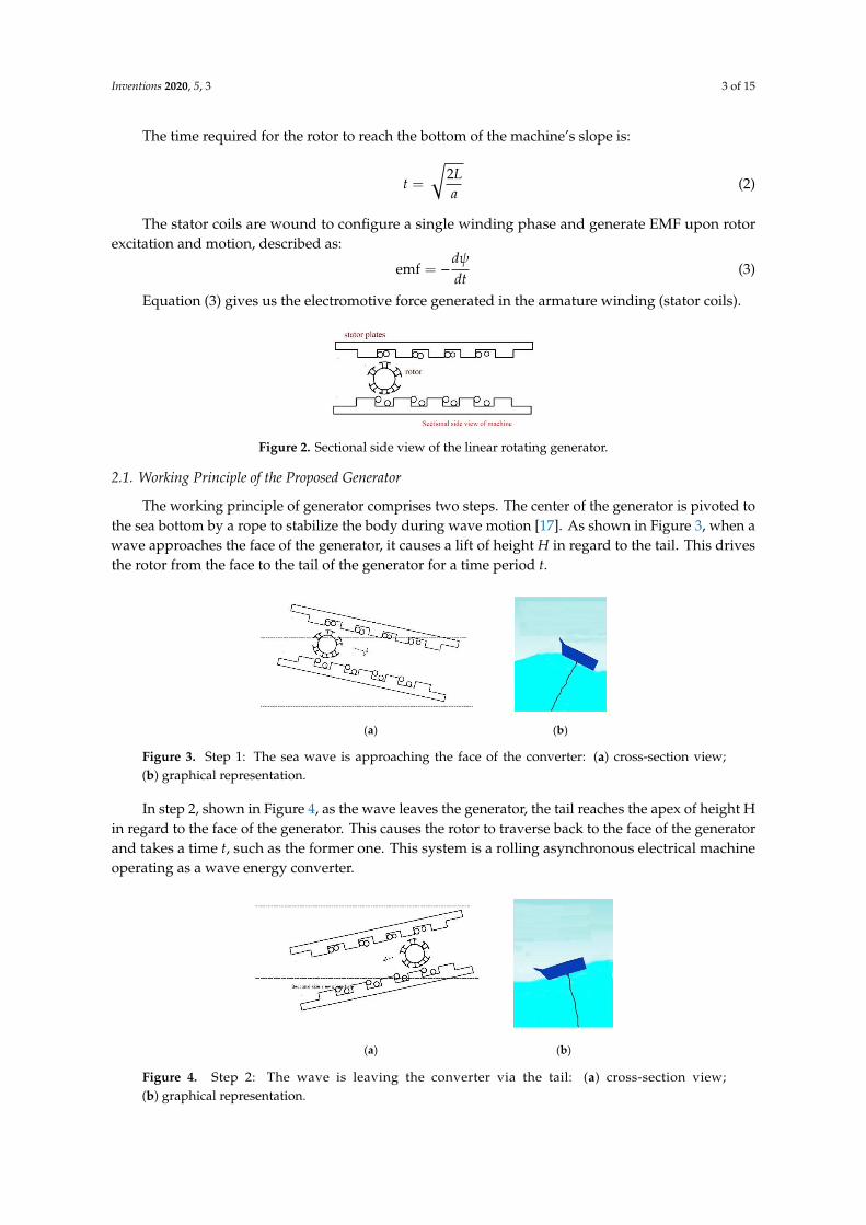
Figure 2. Sectional side view of the linear rotating generator.
2.1. Working Principle of the Proposed Generator
The working principle of generator comprises two steps. The center of the generator is pivoted
to the sea bottom by a rope to stabilize the body during wave motion [17]. As shown in Figure 3,
when a wave approaches the face of the generator, it causes a lift of height 𝐻 in regard to the tail.
This drives the rotor from the face to the tail of the generator for a time period 𝑡.
(a) (b)
Figure 3. Step 1: The sea wave is approaching the face of the converter: (a) cross-section view; (b)
graphical representation.
In step 2, shown in Figure 4, as the wave leaves the generator, the tail reaches the apex of height
H in regard to the face of the generator. This causes the rotor to traverse back to the face of the
generator and takes a time 𝑡, such as the former one. This system is a rolling asynchronous electrical
machine operating as a wave energy converter.
(a) (b)
Figure 4. Step 2: The wave is leaving the converter via the tail: (a) cross-section view; (b) graphical
representation.
Figure 2. Sectional side view of the linear rotating generator.
2.1. Working Principle of the Proposed Generator
The working principle of generator comprises two steps. The center of the generator is pivoted tothe sea bottom by a rope to stabilize the body during wave motion [17]. As shown in Figure 3, when awave approaches the face of the generator, it causes a lift of height H in regard to the tail. This drivesthe rotor from the face to the tail of the generator for a time period t.
Inventions 2020, 5, x 3 of 15
𝑡 = √2𝐿
𝑎 (2)
The stator coils are wound to configure a single winding phase and generate EMF upon rotor
excitation and motion, described as:
emf = −𝑑𝜓
𝑑𝑡 (3)
Equation (3) gives us the electromotive force generated in the armature winding (stator coils).
Figure 2. Sectional side view of the linear rotating generator.
2.1. Working Principle of the Proposed Generator
The working principle of generator comprises two steps. The center of the generator is pivoted
to the sea bottom by a rope to stabilize the body during wave motion [17]. As shown in Figure 3,
when a wave approaches the face of the generator, it causes a lift of height 𝐻 in regard to the tail.
This drives the rotor from the face to the tail of the generator for a time period 𝑡.
(a) (b)
Figure 3. Step 1: The sea wave is approaching the face of the converter: (a) cross-section view; (b)
graphical representation.
In step 2, shown in Figure 4, as the wave leaves the generator, the tail reaches the apex of height
H in regard to the face of the generator. This causes the rotor to traverse back to the face of the
generator and takes a time 𝑡, such as the former one. This system is a rolling asynchronous electrical
machine operating as a wave energy converter.
(a) (b)
Figure 4. Step 2: The wave is leaving the converter via the tail: (a) cross-section view; (b) graphical
representation.
Figure 3. Step 1: The sea wave is approaching the face of the converter: (a) cross-section view;(b) graphical representation.
In step 2, shown in Figure 4, as the wave leaves the generator, the tail reaches the apex of height Hin regard to the face of the generator. This causes the rotor to traverse back to the face of the generatorand takes a time t, such as the former one. This system is a rolling asynchronous electrical machineoperating as a wave energy converter.
Inventions 2020, 5, x 3 of 15
𝑡 = √2𝐿
𝑎 (2)
The stator coils are wound to configure a single winding phase and generate EMF upon rotor
excitation and motion, described as:
emf = −𝑑𝜓
𝑑𝑡 (3)
Equation (3) gives us the electromotive force generated in the armature winding (stator coils).
Figure 2. Sectional side view of the linear rotating generator.
2.1. Working Principle of the Proposed Generator
The working principle of generator comprises two steps. The center of the generator is pivoted
to the sea bottom by a rope to stabilize the body during wave motion [17]. As shown in Figure 3,
when a wave approaches the face of the generator, it causes a lift of height 𝐻 in regard to the tail.
This drives the rotor from the face to the tail of the generator for a time period 𝑡.
(a) (b)
Figure 3. Step 1: The sea wave is approaching the face of the converter: (a) cross-section view; (b)
graphical representation.
In step 2, shown in Figure 4, as the wave leaves the generator, the tail reaches the apex of height
H in regard to the face of the generator. This causes the rotor to traverse back to the face of the
generator and takes a time 𝑡, such as the former one. This system is a rolling asynchronous electrical
machine operating as a wave energy converter.
(a) (b)
Figure 4. Step 2: The wave is leaving the converter via the tail: (a) cross-section view; (b) graphical
representation.
Figure 4. Step 2: The wave is leaving the converter via the tail: (a) cross-section view;(b) graphical representation.
Inventions 2020, 5, 3 4 of 15
2.2. Generation of EMF
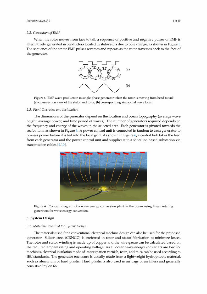
When the rotor moves from face to tail, a sequence of positive and negative pulses of EMF isalternatively generated in conductors located in stator slots due to pole change, as shown in Figure 5.The sequence of the stator EMF pulses reverses and repeats as the rotor traverses back to the face ofthe generator.
Inventions 2020, 5, x 4 of 15
2.2. Generation of EMF
When the rotor moves from face to tail, a sequence of positive and negative pulses of EMF is
alternatively generated in conductors located in stator slots due to pole change, as shown in Figure
5. The sequence of the stator EMF pulses reverses and repeats as the rotor traverses back to the face
of the generator.
Figure 5. EMF wave production in single-phase generator when the rotor is moving from head to tail:
(a) cross-section view of the stator and rotor; (b) corresponding sinusoidal wave form.
2.3 Plant Overview and Installation
The dimensions of the generator depend on the location and ocean topography (average wave
height, average power, and time period of waves). The number of generators required depends on
the frequency and energy of the waves in the selected area. Each generator is pivoted towards the sea
bottom, as shown in Figure 6. A power control unit is connected in tandem to each generator to
process power before it is fed into the local grid. As shown in Figure 6, a central hub takes the feed
from each generator and the power control unit and supplies it to a shoreline-based substation via
transmission cables [9,10].
Figure 6. Concept diagram of a wave energy conversion plant in the ocean using linear rotating
generators for wave energy conversion.
3. System Design
3.1. Materials Required for System Design
The materials used for a conventional electrical machine design can also be used for the
proposed generator. Silicon steel (CRNGO) is preferred in rotor and stator fabrication to minimize
losses. The rotor and stator winding is made up of copper and the wire gauze can be calculated based
on the required ampere rating and operating voltage. As all ocean wave energy converters are low
KV machines, electrical insulation made of impregnation varnish, resin, and mica can be used
according to IEC standards. The generator enclosure is usually made from a lightweight hydrophobic
material, such as aluminum or hard plastic. Hard plastic is also used in air bags or air fillers and
generally consists of nylon 66.
(a)
(b)
Figure 5. EMF wave production in single-phase generator when the rotor is moving from head to tail:(a) cross-section view of the stator and rotor; (b) corresponding sinusoidal wave form.
2.3. Plant Overview and Installation
The dimensions of the generator depend on the location and ocean topography (average waveheight, average power, and time period of waves). The number of generators required depends onthe frequency and energy of the waves in the selected area. Each generator is pivoted towards thesea bottom, as shown in Figure 6. A power control unit is connected in tandem to each generator toprocess power before it is fed into the local grid. As shown in Figure 6, a central hub takes the feedfrom each generator and the power control unit and supplies it to a shoreline-based substation viatransmission cables [9,10].
Inventions 2020, 5, x 4 of 15
2.2. Generation of EMF
When the rotor moves from face to tail, a sequence of positive and negative pulses of EMF is
alternatively generated in conductors located in stator slots due to pole change, as shown in Figure
5. The sequence of the stator EMF pulses reverses and repeats as the rotor traverses back to the face
of the generator.
Figure 5. EMF wave production in single-phase generator when the rotor is moving from head to tail:
(a) cross-section view of the stator and rotor; (b) corresponding sinusoidal wave form.
2.3 Plant Overview and Installation
The dimensions of the generator depend on the location and ocean topography (average wave
height, average power, and time period of waves). The number of generators required depends on
the frequency and energy of the waves in the selected area. Each generator is pivoted towards the sea
bottom, as shown in Figure 6. A power control unit is connected in tandem to each generator to
process power before it is fed into the local grid. As shown in Figure 6, a central hub takes the feed
from each generator and the power control unit and supplies it to a shoreline-based substation via
transmission cables [9,10].
Figure 6. Concept diagram of a wave energy conversion plant in the ocean using linear rotating
generators for wave energy conversion.
3. System Design
3.1. Materials Required for System Design
The materials used for a conventional electrical machine design can also be used for the
proposed generator. Silicon steel (CRNGO) is preferred in rotor and stator fabrication to minimize
losses. The rotor and stator winding is made up of copper and the wire gauze can be calculated based
on the required ampere rating and operating voltage. As all ocean wave energy converters are low
KV machines, electrical insulation made of impregnation varnish, resin, and mica can be used
according to IEC standards. The generator enclosure is usually made from a lightweight hydrophobic
material, such as aluminum or hard plastic. Hard plastic is also used in air bags or air fillers and
generally consists of nylon 66.
(a)
(b)
Figure 6. Concept diagram of a wave energy conversion plant in the ocean using linear rotatinggenerators for wave energy conversion.
3. System Design
3.1. Materials Required for System Design
The materials used for a conventional electrical machine design can also be used for the proposedgenerator. Silicon steel (CRNGO) is preferred in rotor and stator fabrication to minimize losses.The rotor and stator winding is made up of copper and the wire gauze can be calculated based onthe required ampere rating and operating voltage. As all ocean wave energy converters are low KVmachines, electrical insulation made of impregnation varnish, resin, and mica can be used according toIEC standards. The generator enclosure is usually made from a lightweight hydrophobic material,such as aluminum or hard plastic. Hard plastic is also used in air bags or air fillers and generallyconsists of nylon 66.
Inventions 2020, 5, 3 5 of 15
3.2. Proposed Design
The design of the machine is divided in four phases:
(1) Design of the stator;(2) Design of the rotor;(3) Design of the winding;(4) Design of the air-sealing hydrophobic body.
A detailed description of these phases is presented below.
3.2.1. Stator Design
The stator is composed of two slotted plates with a concentric single-phase armature winding.The design of the stator requires parameters including the total length of the wave energy converter,stator plate length, number of slots, stator slot pitch, tooth width, slot depth, and depth of the statorcore. Slot length l depends on the required KVA. The total length of the wave energy converter isdetermined from the height and length of the wave.
L1 =
√(H2 +
(λ2
)2) (4)
The optimal length is modified as follows:
L1 =
√(H2 +
(λ
1.6
)2) (5)
The acceleration of the rotor when the converter increases to its maximum capacity can becalculated by Equation (1).
sin(θ) =HL1
(6)
From Equations (1) and (5), it is easy to find the length of machine, where t is equal to half thetime period of the wave.
L =at2
2(7)
Here, T/2 − t is the time for which the rotor is in an idle position, which should be reducedbecause of the increasing quality of the output power of the generator.
Both halves of the generated voltage waveform are related to a voltage pulse in individual slots.To improve the quality of the output power, the number of slots in a single stator plate is calibratedbased on the time period of the wave.
Ns = f× t (8)
Here, f is the grid frequency (50 Hz for India, the United Kingdom, and most of Europe, 60 Hz forthe United States) and the speed of the rotor Ns is calculated from Equation (8).
Equation (3) gives the EMF generated per slot. Each slot in the stator plate contributes to halfa cycle in the sinusoidal EMF seen in Figure 5. The number of conductors is calculated by the EMFgenerated per slot as follows:
N =Es
Bav ×Kw × 2×π× f × l×w(9)
where:w =
Ln
(10)
Inventions 2020, 5, 3 6 of 15
In general, the number of turns is calculated based on a predetermined length (l) of the conductor.The product of the number of conductive layers per slot and the diameter of the wire gives theslot width.
tooth width = w− slot width (11)
In a low KVA generator, the tooth width is around 0.5–1 inch, whereas in a turbo generator the itis greater than 3 inches. The depth of the slot preferably should not exceed 3 times the slot width, so:
dc =ϕ
2× Bc × Li(12)
Using Equations (4)–(12), we can design the stator part of the generator.The time period of the wave is less than that of the rotor for practical ocean wave values. Therefore,
every wave energy converter contains many numbers of electrical conversion units.
3.2.2. Design of the Rotor
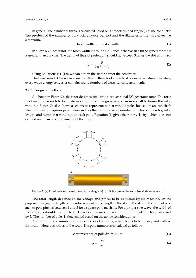
As shown in Figure 7a, the rotor design is similar to a conventional DC generator rotor. The rotorhas two circular ends to facilitate motion in machine grooves and an iron shaft to house the rotorwinding. Figure 7b also shows a schematic representation of winded poles housed on an iron shaft.The rotor design requires parameters such as the rotor diameter, number of poles on the rotor, rotorlength, and number of windings on each pole. Equation (1) gives the rotor velocity, which does notdepend on the mass and diameter of the rotor.
Inventions 2020, 5, x 6 of 15
In general, the number of turns is calculated based on a predetermined length ( 𝑙 ) of the
conductor. The product of the number of conductive layers per slot and the diameter of the wire gives
the slot width.
tooth width = 𝑤 − slot width (11)
In a low KVA generator, the tooth width is around 0.5–1 inch, whereas in a turbo generator the
it is greater than 3 inches. The depth of the slot preferably should not exceed 3 times the slot width,
so:
𝑑𝑐 =𝜑
2 × 𝐵𝑐 × 𝐿𝑖 (12)
Using Equations (4)–(12), we can design the stator part of the generator.
The time period of the wave is less than that of the rotor for practical ocean wave values.
Therefore, every wave energy converter contains many numbers of electrical conversion units.
3.2.2 Design of the Rotor
As shown in Figure 7a, the rotor design is similar to a conventional DC generator rotor. The rotor
has two circular ends to facilitate motion in machine grooves and an iron shaft to house the rotor
winding. Figure 7b also shows a schematic representation of winded poles housed on an iron shaft.
The rotor design requires parameters such as the rotor diameter, number of poles on the rotor, rotor
length, and number of windings on each pole. Equation (1) gives the rotor velocity, which does not
depend on the mass and diameter of the rotor.
(a)
(b)
Figure 7. (a) Front view of the rotor (semantic diagram). (b) Side view of the rotor (solid state
diagram).
The rotor length depends on the voltage and power to be delivered by the machine. In the
proposed design, the length of the rotor is equal to the length of the slot in the stator. The ratio of pole
arch to pole pitch is between 1 and 5 for a square pole machine. For a proper sine wave, the width of
the pole arcs should be equal to 𝑤. Therefore, the maximum and minimum pole pitch are 𝑤/2 and
𝑤/5. The number of poles is determined based on the above considerations.
An inappropriate number of poles causes slot slipping, which leads to frequency and voltage
distortion. Here, 𝑟 is radius of the rotor. The pole number is calculated as follows:
circumference of pole drum = 2𝜋𝑟 (13)
p =2𝜋𝑟
𝑤 (14)
The number of turns is derived based on the flux per pole for a fixed current.
Figure 7. (a) Front view of the rotor (semantic diagram). (b) Side view of the rotor (solid state diagram).
The rotor length depends on the voltage and power to be delivered by the machine. In theproposed design, the length of the rotor is equal to the length of the slot in the stator. The ratio of polearch to pole pitch is between 1 and 5 for a square pole machine. For a proper sine wave, the width ofthe pole arcs should be equal to w. Therefore, the maximum and minimum pole pitch are w/2 andw/5. The number of poles is determined based on the above considerations.
An inappropriate number of poles causes slot slipping, which leads to frequency and voltagedistortion. Here, r is radius of the rotor. The pole number is calculated as follows:
circumference of pole drum = 2πr (13)
p =2πrw
(14)
Inventions 2020, 5, 3 7 of 15
The number of turns is derived based on the flux per pole for a fixed current.
ϕ =Bav ×π× l×D
p(15)
where Bav is an average flux density.
ϕ =N × i× µ×A
l(16)
The number of turns on a single pole is calculated through Equation (16). The diameter of the endring is at least half the diameter of the pole drum in order to maintain and manage mechanical stresson the rotor while rotating.
Two strands of windings from each pole of the rotor are connected to a copper band on either ofthe end rings of the rotor. These end rings are used to excite the rotor coils into energy conversion.The winding is done in tandem along the length of the rotor. Alternate magnetic poles are achieved bychanging the direction of the winding. The rotor excitation current enters through one end ring andleaves through the other. The number of poles in the rotor depends on the diameter of the rotor andthe required KVA.
3.2.3. Design of the Winding
The rotor winding is of the salient pole type and alternate poles are achieved by changing thedirection of the winding pattern. The number of turns in a single pole is calculated using Equation (15).
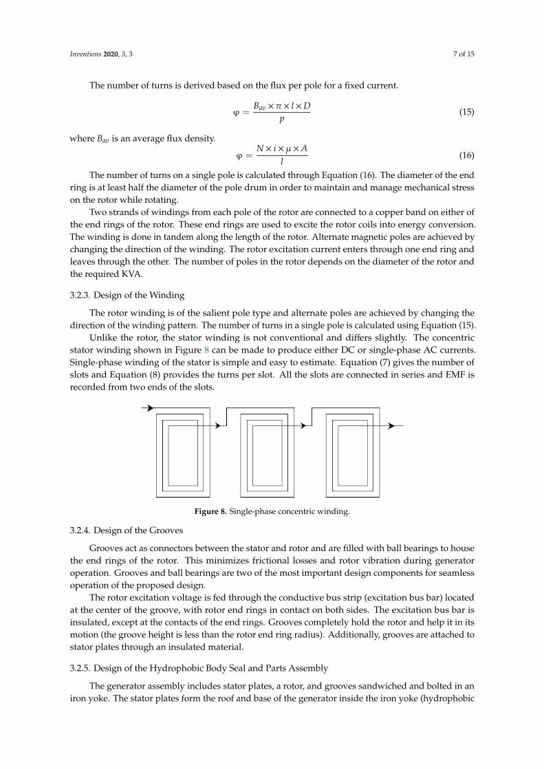
Unlike the rotor, the stator winding is not conventional and differs slightly. The concentricstator winding shown in Figure 8 can be made to produce either DC or single-phase AC currents.Single-phase winding of the stator is simple and easy to estimate. Equation (7) gives the number ofslots and Equation (8) provides the turns per slot. All the slots are connected in series and EMF isrecorded from two ends of the slots.
Inventions 2020, 5, x 7 of 15
φ =𝐵𝑎𝑣 × 𝜋 × 𝑙 × 𝐷
𝑝 (15)
where 𝐵𝑎𝑣 is an average flux density.
φ =𝑁 × 𝑖 × 𝜇 × 𝐴
𝑙 (16)
The number of turns on a single pole is calculated through Equation (16). The diameter of the
end ring is at least half the diameter of the pole drum in order to maintain and manage mechanical
stress on the rotor while rotating.
Two strands of windings from each pole of the rotor are connected to a copper band on either of
the end rings of the rotor. These end rings are used to excite the rotor coils into energy conversion.
The winding is done in tandem along the length of the rotor. Alternate magnetic poles are achieved
by changing the direction of the winding. The rotor excitation current enters through one end ring
and leaves through the other. The number of poles in the rotor depends on the diameter of the rotor
and the required KVA.
3.2.3. Design of the Winding
The rotor winding is of the salient pole type and alternate poles are achieved by changing the
direction of the winding pattern. The number of turns in a single pole is calculated using Equation
(15).
Unlike the rotor, the stator winding is not conventional and differs slightly. The concentric stator
winding shown in Figure 8 can be made to produce either DC or single-phase AC currents. Single-
phase winding of the stator is simple and easy to estimate. Equation (7) gives the number of slots and
Equation (8) provides the turns per slot. All the slots are connected in series and EMF is recorded from
two ends of the slots.
Figure 8. Single-phase concentric winding.
3.2.4. Design of the Grooves
Grooves act as connectors between the stator and rotor and are filled with ball bearings to house
the end rings of the rotor. This minimizes frictional losses and rotor vibration during generator
operation. Grooves and ball bearings are two of the most important design components for seamless
operation of the proposed design.
The rotor excitation voltage is fed through the conductive bus strip (excitation bus bar) located
at the center of the groove, with rotor end rings in contact on both sides. The excitation bus bar is
insulated, except at the contacts of the end rings. Grooves completely hold the rotor and help it in its
motion (the groove height is less than the rotor end ring radius). Additionally, grooves are attached
to stator plates through an insulated material.
3.2.5. Design of the Hydrophobic Body Seal and Parts Assembly
The generator assembly includes stator plates, a rotor, and grooves sandwiched and bolted in
an iron yoke. The stator plates form the roof and base of the generator inside the iron yoke
(hydrophobic body) between two groves. The rotor with the end rings is placed in groves in such a
Figure 8. Single-phase concentric winding.
3.2.4. Design of the Grooves
Grooves act as connectors between the stator and rotor and are filled with ball bearings to housethe end rings of the rotor. This minimizes frictional losses and rotor vibration during generatoroperation. Grooves and ball bearings are two of the most important design components for seamlessoperation of the proposed design.
The rotor excitation voltage is fed through the conductive bus strip (excitation bus bar) locatedat the center of the groove, with rotor end rings in contact on both sides. The excitation bus bar isinsulated, except at the contacts of the end rings. Grooves completely hold the rotor and help it in itsmotion (the groove height is less than the rotor end ring radius). Additionally, grooves are attached tostator plates through an insulated material.
3.2.5. Design of the Hydrophobic Body Seal and Parts Assembly
The generator assembly includes stator plates, a rotor, and grooves sandwiched and bolted in aniron yoke. The stator plates form the roof and base of the generator inside the iron yoke (hydrophobic
Inventions 2020, 5, 3 8 of 15
body) between two groves. The rotor with the end rings is placed in groves in such a way that the poledrum faces the stator plate. Air vents are provided on top of the yoke to enable cooling in the generator.
The hydrophobic body of the converter has three chambers made from a lightweight hydrophobicmaterial (aluminum). The top and bottom chambers are filled with air balloons and the middle onehosts the designed linear rotating electrical generator.
Figure 9 shows the shape of the sealing vessel and is designed in such a way so as to providemaximum lift when the wave hits the face of the converter. Maximum lift of the converter enables themaximum amount of energy to be extracted from ocean waves.
Inventions 2020, 5, x 8 of 15
way that the pole drum faces the stator plate. Air vents are provided on top of the yoke to enable
cooling in the generator.
The hydrophobic body of the converter has three chambers made from a lightweight
hydrophobic material (aluminum). The top and bottom chambers are filled with air balloons and the
middle one hosts the designed linear rotating electrical generator.
Figure 9 shows the shape of the sealing vessel and is designed in such a way so as to provide
maximum lift when the wave hits the face of the converter. Maximum lift of the converter enables
the maximum amount of energy to be extracted from ocean waves.
Figure 9. Block diagram of a total wave energy converter with casing.
4. Modeling and Simulation
A virtual simulation study with the help of finite element analysis is carried out on the proposed
design to understand the flux linkage throughout the generator. In addition, a scaled-down prototype
is fabricated using locally sourced materials to further validate the simulation analysis and proof of
concept.
A 2D finite element analysis (FEA) is performed using the electrical parameters of the generator.
Figure 10 shows that the geometry of the generator chosen for the FEA is analogous to the physical
system. In this generator are two mechanical coordinates. One of them is the distance between the
center of the rotor and the end of the stator plate. The other one is the angle of rotation of the rotor
with respect to a coordinate system stacked onto the rotor. A complete parametric design is shown
in Figure 11. The parametric design allows detailed analysis of the generator at any selected rotor
position. Figure 12 shows magnetic flux distribution due to an excited rotor in an arbitrary position.
Figure 10. Prepared geometry for finite element analysis (FEA).
Figure 9. Block diagram of a total wave energy converter with casing.
4. Modeling and Simulation
A virtual simulation study with the help of finite element analysis is carried out on the proposeddesign to understand the flux linkage throughout the generator. In addition, a scaled-down prototypeis fabricated using locally sourced materials to further validate the simulation analysis and proofof concept.
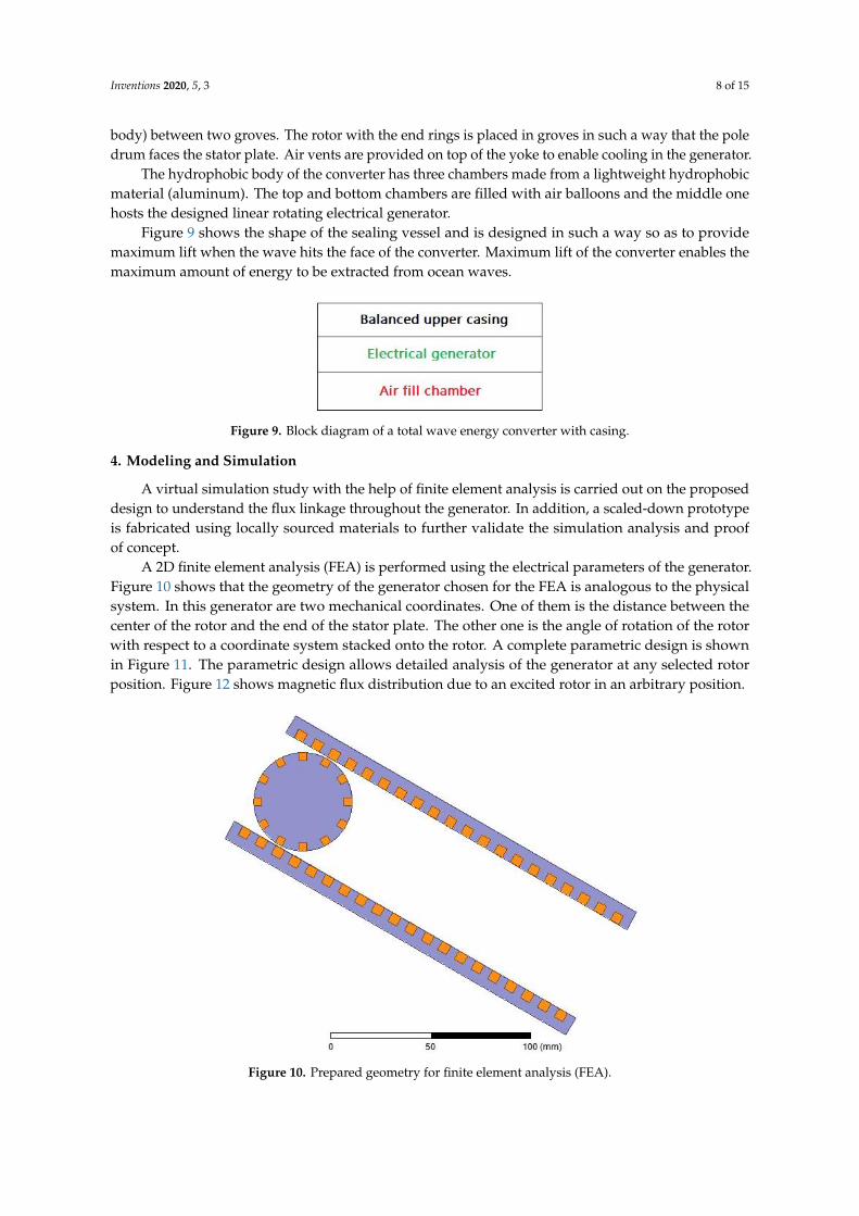
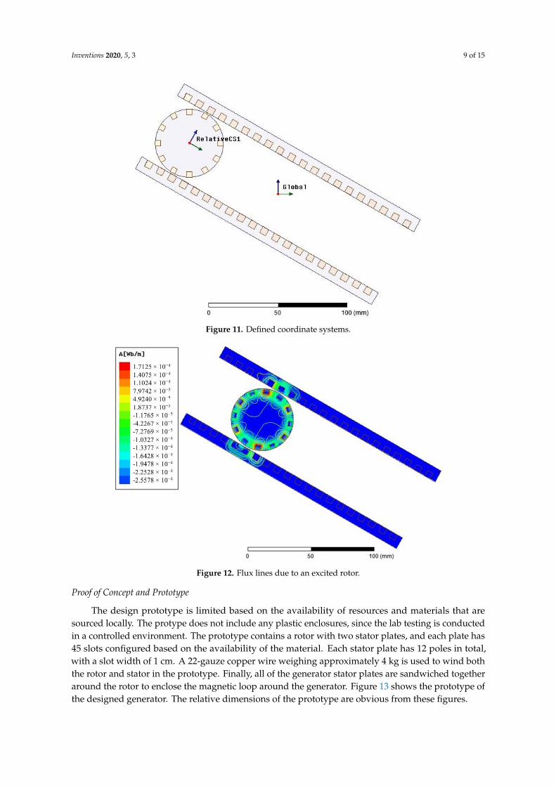
A 2D finite element analysis (FEA) is performed using the electrical parameters of the generator.Figure 10 shows that the geometry of the generator chosen for the FEA is analogous to the physicalsystem. In this generator are two mechanical coordinates. One of them is the distance between thecenter of the rotor and the end of the stator plate. The other one is the angle of rotation of the rotorwith respect to a coordinate system stacked onto the rotor. A complete parametric design is shownin Figure 11. The parametric design allows detailed analysis of the generator at any selected rotorposition. Figure 12 shows magnetic flux distribution due to an excited rotor in an arbitrary position.
Inventions 2020, 5, x 8 of 15
way that the pole drum faces the stator plate. Air vents are provided on top of the yoke to enable
cooling in the generator.
The hydrophobic body of the converter has three chambers made from a lightweight
hydrophobic material (aluminum). The top and bottom chambers are filled with air balloons and the
middle one hosts the designed linear rotating electrical generator.
Figure 9 shows the shape of the sealing vessel and is designed in such a way so as to provide
maximum lift when the wave hits the face of the converter. Maximum lift of the converter enables
the maximum amount of energy to be extracted from ocean waves.
Figure 9. Block diagram of a total wave energy converter with casing.
4. Modeling and Simulation
A virtual simulation study with the help of finite element analysis is carried out on the proposed
design to understand the flux linkage throughout the generator. In addition, a scaled-down prototype
is fabricated using locally sourced materials to further validate the simulation analysis and proof of
concept.
A 2D finite element analysis (FEA) is performed using the electrical parameters of the generator.
Figure 10 shows that the geometry of the generator chosen for the FEA is analogous to the physical
system. In this generator are two mechanical coordinates. One of them is the distance between the
center of the rotor and the end of the stator plate. The other one is the angle of rotation of the rotor
with respect to a coordinate system stacked onto the rotor. A complete parametric design is shown
in Figure 11. The parametric design allows detailed analysis of the generator at any selected rotor
position. Figure 12 shows magnetic flux distribution due to an excited rotor in an arbitrary position.
Figure 10. Prepared geometry for finite element analysis (FEA). Figure 10. Prepared geometry for finite element analysis (FEA).
Inventions 2020, 5, 3 9 of 15Inventions 2020, 5, x 9 of 15
Figure 11. Defined coordinate systems.
Figure 12. Flux lines due to an excited rotor.
Proof of Concept and Prototype
The design prototype is limited based on the availability of resources and materials that are
sourced locally. The protype does not include any plastic enclosures, since the lab testing is conducted
in a controlled environment. The prototype contains a rotor with two stator plates, and each plate has
45 slots configured based on the availability of the material. Each stator plate has 12 poles in total,
with a slot width of 1 cm. A 22-gauze copper wire weighing approximately 4 kg is used to wind both
the rotor and stator in the prototype. Finally, all of the generator stator plates are sandwiched together
around the rotor to enclose the magnetic loop around the generator. Figure 13 shows the prototype
of the designed generator. The relative dimensions of the prototype are obvious from these figures.
Figure 11. Defined coordinate systems.
Inventions 2020, 5, x 9 of 15
Figure 11. Defined coordinate systems.
Figure 12. Flux lines due to an excited rotor.
Proof of Concept and Prototype
The design prototype is limited based on the availability of resources and materials that are
sourced locally. The protype does not include any plastic enclosures, since the lab testing is conducted
in a controlled environment. The prototype contains a rotor with two stator plates, and each plate has
45 slots configured based on the availability of the material. Each stator plate has 12 poles in total,
with a slot width of 1 cm. A 22-gauze copper wire weighing approximately 4 kg is used to wind both
the rotor and stator in the prototype. Finally, all of the generator stator plates are sandwiched together
around the rotor to enclose the magnetic loop around the generator. Figure 13 shows the prototype
of the designed generator. The relative dimensions of the prototype are obvious from these figures.
Figure 12. Flux lines due to an excited rotor.
Proof of Concept and Prototype
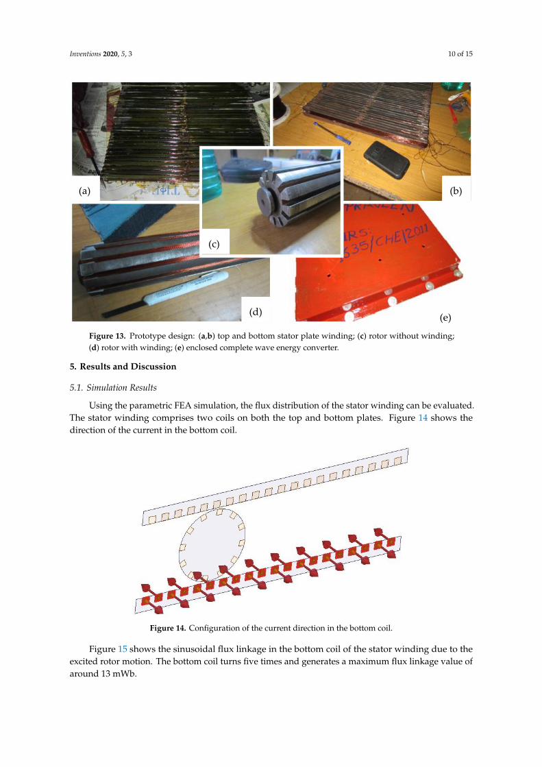
The design prototype is limited based on the availability of resources and materials that aresourced locally. The protype does not include any plastic enclosures, since the lab testing is conductedin a controlled environment. The prototype contains a rotor with two stator plates, and each plate has45 slots configured based on the availability of the material. Each stator plate has 12 poles in total,with a slot width of 1 cm. A 22-gauze copper wire weighing approximately 4 kg is used to wind boththe rotor and stator in the prototype. Finally, all of the generator stator plates are sandwiched togetheraround the rotor to enclose the magnetic loop around the generator. Figure 13 shows the prototype ofthe designed generator. The relative dimensions of the prototype are obvious from these figures.
Inventions 2020, 5, 3 10 of 15Inventions 2020, 5, x 10 of 15
Figure 13. Prototype design: (a,b) top and bottom stator plate winding; (c) rotor without winding; (d)
rotor with winding; (e) enclosed complete wave energy converter.
5. Results and Discussion
5.1 Simulation Results
Using the parametric FEA simulation, the flux distribution of the stator winding can be
evaluated. The stator winding comprises two coils on both the top and bottom plates. Figure 14 shows
the direction of the current in the bottom coil.
Figure 14. Configuration of the current direction in the bottom coil.
Figure 15 shows the sinusoidal flux linkage in the bottom coil of the stator winding due to the
excited rotor motion. The bottom coil turns five times and generates a maximum flux linkage value of
around 13 mWb.
(a) (b)
(c)
(d) (e)
Figure 13. Prototype design: (a,b) top and bottom stator plate winding; (c) rotor without winding;(d) rotor with winding; (e) enclosed complete wave energy converter.
5. Results and Discussion
5.1. Simulation Results
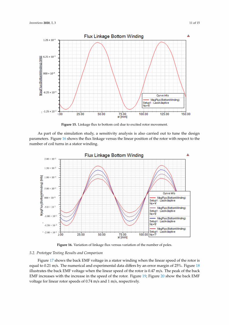
Using the parametric FEA simulation, the flux distribution of the stator winding can be evaluated.The stator winding comprises two coils on both the top and bottom plates. Figure 14 shows thedirection of the current in the bottom coil.
Inventions 2020, 5, x 10 of 15
Figure 13. Prototype design: (a,b) top and bottom stator plate winding; (c) rotor without winding; (d)
rotor with winding; (e) enclosed complete wave energy converter.
5. Results and Discussion
5.1 Simulation Results
Using the parametric FEA simulation, the flux distribution of the stator winding can be
evaluated. The stator winding comprises two coils on both the top and bottom plates. Figure 14 shows
the direction of the current in the bottom coil.
Figure 14. Configuration of the current direction in the bottom coil.
Figure 15 shows the sinusoidal flux linkage in the bottom coil of the stator winding due to the
excited rotor motion. The bottom coil turns five times and generates a maximum flux linkage value of
around 13 mWb.
(a) (b)
(c)
(d) (e)
Figure 14. Configuration of the current direction in the bottom coil.
Figure 15 shows the sinusoidal flux linkage in the bottom coil of the stator winding due to theexcited rotor motion. The bottom coil turns five times and generates a maximum flux linkage value ofaround 13 mWb.
Inventions 2020, 5, 3 11 of 15Inventions 2020, 5, x 11 of 15
Figure 15. Linkage flux to bottom coil due to excited rotor movement.
As part of the simulation study, a sensitivity analysis is also carried out to tune the design
parameters. Figure 16 shows the flux linkage versus the linear position of the rotor with respect to
the number of coil turns in a stator winding.
Figure 16. Variation of linkage flux versus variation of the number of poles.
5.2 Prototype Testing Results and Comparison
Figure 17 shows the back EMF voltage in a stator winding when the linear speed of the rotor is
equal to 0.21 m/s. The numerical and experimental data differs by an error margin of 25%. Figure 18
illustrates the back EMF voltage when the linear speed of the rotor is 0.47 m/s. The peak of the back
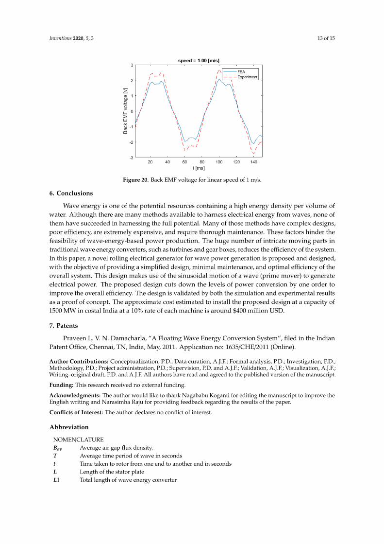
EMF increases with the increase in the speed of the rotor. Figures 19 and 20 show the back EMF
voltage for linear rotor speeds of 0.74 m/s and 1 m/s, respectively.
Figure 15. Linkage flux to bottom coil due to excited rotor movement.
As part of the simulation study, a sensitivity analysis is also carried out to tune the designparameters. Figure 16 shows the flux linkage versus the linear position of the rotor with respect to thenumber of coil turns in a stator winding.
Inventions 2020, 5, x 11 of 15
Figure 15. Linkage flux to bottom coil due to excited rotor movement.
As part of the simulation study, a sensitivity analysis is also carried out to tune the design
parameters. Figure 16 shows the flux linkage versus the linear position of the rotor with respect to
the number of coil turns in a stator winding.
Figure 16. Variation of linkage flux versus variation of the number of poles.
5.2 Prototype Testing Results and Comparison
Figure 17 shows the back EMF voltage in a stator winding when the linear speed of the rotor is
equal to 0.21 m/s. The numerical and experimental data differs by an error margin of 25%. Figure 18
illustrates the back EMF voltage when the linear speed of the rotor is 0.47 m/s. The peak of the back
EMF increases with the increase in the speed of the rotor. Figures 19 and 20 show the back EMF
voltage for linear rotor speeds of 0.74 m/s and 1 m/s, respectively.
Figure 16. Variation of linkage flux versus variation of the number of poles.
5.2. Prototype Testing Results and Comparison
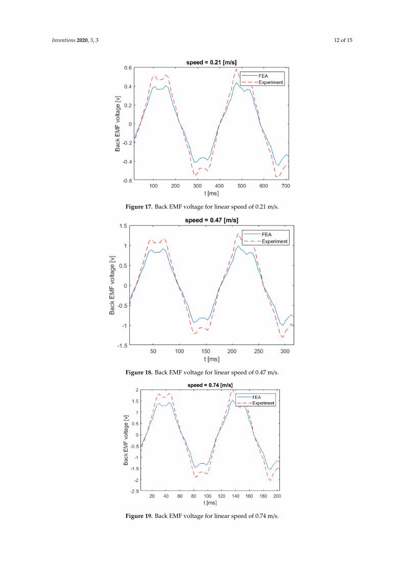
Figure 17 shows the back EMF voltage in a stator winding when the linear speed of the rotor isequal to 0.21 m/s. The numerical and experimental data differs by an error margin of 25%. Figure 18illustrates the back EMF voltage when the linear speed of the rotor is 0.47 m/s. The peak of the backEMF increases with the increase in the speed of the rotor. Figure 19; Figure 20 show the back EMFvoltage for linear rotor speeds of 0.74 m/s and 1 m/s, respectively.
Inventions 2020, 5, 3 12 of 15Inventions 2020, 5, x 12 of 15
Figure 17. Back EMF voltage for linear speed of 0.21 m/s.
Figure 18. Back EMF voltage for linear speed of 0.47 m/s.
Figure 17. Back EMF voltage for linear speed of 0.21 m/s.
Inventions 2020, 5, x 12 of 15
Figure 17. Back EMF voltage for linear speed of 0.21 m/s.
Figure 18. Back EMF voltage for linear speed of 0.47 m/s. Figure 18. Back EMF voltage for linear speed of 0.47 m/s.Inventions 2020, 5, x 13 of 15
Figure 19. Back EMF voltage for linear speed of 0.74 m/s.
Figure 20. Back EMF voltage for linear speed of 1 m/s.
6. Conclusions
Wave energy is one of the potential resources containing a high energy density per volume of
water. Although there are many methods available to harness electrical energy from waves, none of
them have succeeded in harnessing the full potential. Many of those methods have complex designs,
poor efficiency, are extremely expensive, and require thorough maintenance. These factors hinder
the feasibility of wave-energy-based power production. The huge number of intricate moving parts
in traditional wave energy converters, such as turbines and gear boxes, reduces the efficiency of the
system. In this paper, a novel rolling electrical generator for wave power generation is proposed and
designed, with the objective of providing a simplified design, minimal maintenance, and optimal
efficiency of the overall system. This design makes use of the sinusoidal motion of a wave (prime
mover) to generate electrical power. The proposed design cuts down the levels of power conversion
by one order to improve the overall efficiency. The design is validated by both the simulation and
experimental results as a proof of concept. The approximate cost estimated to install the proposed
design at a capacity of 1500 MW in costal India at a 10% rate of each machine is around $400 million
USD.
Figure 19. Back EMF voltage for linear speed of 0.74 m/s.
Inventions 2020, 5, 3 13 of 15
Inventions 2020, 5, x 13 of 15
Figure 19. Back EMF voltage for linear speed of 0.74 m/s.
Figure 20. Back EMF voltage for linear speed of 1 m/s.
6. Conclusions
Wave energy is one of the potential resources containing a high energy density per volume of
water. Although there are many methods available to harness electrical energy from waves, none of
them have succeeded in harnessing the full potential. Many of those methods have complex designs,
poor efficiency, are extremely expensive, and require thorough maintenance. These factors hinder
the feasibility of wave-energy-based power production. The huge number of intricate moving parts
in traditional wave energy converters, such as turbines and gear boxes, reduces the efficiency of the
system. In this paper, a novel rolling electrical generator for wave power generation is proposed and
designed, with the objective of providing a simplified design, minimal maintenance, and optimal
efficiency of the overall system. This design makes use of the sinusoidal motion of a wave (prime
mover) to generate electrical power. The proposed design cuts down the levels of power conversion
by one order to improve the overall efficiency. The design is validated by both the simulation and
experimental results as a proof of concept. The approximate cost estimated to install the proposed
design at a capacity of 1500 MW in costal India at a 10% rate of each machine is around $400 million
USD.
Figure 20. Back EMF voltage for linear speed of 1 m/s.
6. Conclusions
Wave energy is one of the potential resources containing a high energy density per volume ofwater. Although there are many methods available to harness electrical energy from waves, none ofthem have succeeded in harnessing the full potential. Many of those methods have complex designs,poor efficiency, are extremely expensive, and require thorough maintenance. These factors hinder thefeasibility of wave-energy-based power production. The huge number of intricate moving parts intraditional wave energy converters, such as turbines and gear boxes, reduces the efficiency of the system.In this paper, a novel rolling electrical generator for wave power generation is proposed and designed,with the objective of providing a simplified design, minimal maintenance, and optimal efficiency of theoverall system. This design makes use of the sinusoidal motion of a wave (prime mover) to generateelectrical power. The proposed design cuts down the levels of power conversion by one order toimprove the overall efficiency. The design is validated by both the simulation and experimental resultsas a proof of concept. The approximate cost estimated to install the proposed design at a capacity of1500 MW in costal India at a 10% rate of each machine is around $400 million USD.
7. Patents
Praveen L. V. N. Damacharla, “A Floating Wave Energy Conversion System”, filed in the IndianPatent Office, Chennai, TN, India, May, 2011. Application no: 1635/CHE/2011 (Online).
Author Contributions: Conceptualization, P.D.; Data curation, A.J.F.; Formal analysis, P.D.; Investigation, P.D.;Methodology, P.D.; Project administration, P.D.; Supervision, P.D. and A.J.F.; Validation, A.J.F.; Visualization, A.J.F.;Writing–original draft, P.D. and A.J.F. All authors have read and agreed to the published version of the manuscript.
Funding: This research received no external funding.
Acknowledgments: The author would like to thank Nagababu Koganti for editing the manuscript to improve theEnglish writing and Narasimha Raju for providing feedback regarding the results of the paper.
Conflicts of Interest: The author declares no conflict of interest.
Abbreviation
NOMENCLATUREBav Average air gap flux density.T Average time period of wave in secondst Time taken to rotor from one end to another end in secondsL Length of the stator plateL1 Total length of wave energy converter
Inventions 2020, 5, 3 14 of 15
g Acceleration due to gravityH Average height of the tideλ Wave lengthEs Maximum output voltageKw Winding factorN Number of turnsψ Flux linkageϕ Flux per polea Acceleration of rotorf Frequency of generationNS Number of slotsw Total slot width (tooth width + slot pitch)µ Permeability of materialp Number of polesD Diameter of the rotorr Radius of rotor
References
1. Henderson, R. Design, simulation, and testing of a novel hydraulic power take-off system for the Pelamiswave energy converter. Renew. Energy 2006, 31, 271–283. [CrossRef]
2. Everett, R.; Boyle, G.; Peake, S.; Ramage, J. Energy Systems and Sustainability: Power for a Sustainable Future;Oxford University Press: Oxford, UK, 2012.
3. Jacobson, P.T.; Hagerman, G.; Scott, G. Mapping and Assessment of the United States Ocean Wave Energy Resource;Electric Power Research Institute: Palo Alto, CA, USA, 2011.
4. Karayaka, H.B.; Mahlke, H.; Bogucki, D.; Mehrubeoglu, M. A rotational wave energy conversion systemdevelopment and validation with real ocean wave data. In Proceedings of the 2011 IEEE Power and EnergySociety General Meeting, Detroit, MI, USA, 24–28 July 2011; pp. 1–7.
5. Negri, M.; Malavasi, S. Wave Energy Harnessing in Shallow Water through Oscillating Bodies. Energies 2018,11, 2730. [CrossRef]
6. Hazra, S. Power Generation and Energy Storage Integration for Wave Energy Conversion System; North CarolinaState University: Raleigh, NC, USA, 2017.
7. Czech, B.; Bauer, P. Wave energy converter concepts: Design challenges and classification. IEEE Ind. Electron.Mag. 2012, 6, 4–16. [CrossRef]
8. Drew, B.; Plummer, A.R.; Sahinkaya, M.N. A Review of Wave Energy Converter Technology; Sage PublicationsSage UK: London, UK, 2009.
9. Damacharla, L.V.N.P. A FLOATING WAVE ENERGY CONVERSION SYSTEM. 2011. Available online:http://ipindia.nic.in/ipr/patent/journal_archieve/journal_2011/pat_arch_052011/official_journal_27052011_part_i.pdf (accessed on 26 June 2019).
10. Damacharla, P. Design of Linear Rotating Generator for Wave Energy Converter. In Proceedings of theInternational Conference Renewable and Sustainable Energies 2010 (ICRSE 2010), Hyderabad, AP, India,18 December 2010; p. 4.
11. Clément, A.; McCullen, P.; Falcão, A.; Fiorentino, A.; Gardner, F.; Hammarlund, K.; Lemonis, G.; Lewis, T.;Nielsen, K.; Petroncini, S.; et al. Wave energy in Europe: Current status and perspectives. Renew. Sustain.Energy Rev. 2002, 6, 405–431.
12. Pyrhonen, J.; Jokinen, T.; Hrabovcova, V. Design of Rotating Electrical Machines; John Wiley & Son: Hoboken,NJ, USA, 2013.
13. Say, M.G. Performance and Design of AC Machines; English CBS Publishers Distributors: New Delhi, India, 1995.14. Fang, H.-W.; Song, R.-N.; Xiao, Z.-X. Optimal Design of Permanent Magnet Linear Generator and Its
Application in a Wave Energy Conversion System. Energies 2018, 11, 3109. [CrossRef]15. Singh, S.K. Rolling Along an Incline. Available online: https://cnx.org/contents/[email protected]:
qte40QR6@9/Rolling-along-an-incline (accessed on 11 May 2019).

Inventions 2020, 5, 3 15 of 15
16. Leijon, M.; Danielsson, O.; Eriksson, M.; Thorburn, K.; Bernhoff, H.; Isberg, J.; Sundberg, J.; Ivanova, I.;Sjöstedt, E.; Ågren, O. An electrical approach to wave energy conversion. Renew. Energy 2006, 31, 1309–1319.[CrossRef]
17. Mei, D. Electrical thrust in opposite direction of aggressive submarine. Mar. Electr. Electron. Technol. 1995,2, 30–35.
© 2020 by the authors. Licensee MDPI, Basel, Switzerland. This article is an open accessarticle distributed under the terms and conditions of the Creative Commons Attribution(CC BY) license (http://creativecommons.org/licenses/by/4.0/).