Embed Size (px)
Citation preview
A Robot System Design for Low-Cost Multi-Robot Manipulation
James McLurkin1, Adam McMullen2, Nick Robbins2, Golnaz Habibi1, Aaron Becker1, Alvin Chou2,Hao Li2, Meagan John1, Nnena Okeke3, Joshua Rykowski4, Sunny Kim1, William Xie3, Taylor Vaughn3,
Yu Zhou1, Jennifer Shen1, Nelson Chen1, Quillan Kaseman1, Lindsay Langford3, Jeremy Hunt3,Amanda Boone2, Kevin Koch2
Abstract—Multi-robot manipulation allows for scalable envi-ronmental interaction, which is critical for multi-robot systemsto have an impact on our world. A successful manipulationmodel requires cost-effective robots, robust hardware, andproper system feedback and control. This paper details keysensing and manipulator capabilities of the r-one robot. Ther-one robot is an advanced, open source, low-cost platformfor multi-robot manipulation and sensing that meets allof these requirements. The parts cost is around $250 perrobot. The r-one has a rich sensor suite, including a flexibleIR communication/localization/obstacle detection system, high-precision quadrature encoders, gyroscope, accelerometer, inte-grated bump sensor, and light sensors. Two years of workingwith these robots inspired the development of an external ma-nipulator that gives the robots the ability to interact with theirenvironment. This paper presents an overview of the r-one,the r-one manipulator, and basic manipulation experiments toillustrate the efficacy our design. The advanced design, lowcost, and small size can support university research with largepopulations of robots and multi-robot curriculum in computerscience, electrical engineering, and mechanical engineering. Weconclude with remarks on the future implementation of themanipulators and expected work to follow.
I. INTRODUCTION AND RELATED WORK
Multi-robot systems have great potential for many prac-tical applications. Exploration, mapping, search and rescue,surveillance, manipulation, and construction are all applica-tions where multi-robot systems can have a large impact.In particular, large populations (100—10,000) can producebreakthrough solutions for multi-robot manipulation, withthe ability to transport large numbers of objects of varyingsize. In this paper, we describe our approach to sensing andactuation for multi-robot manipulation. We identify threekey components: a localization sensor to determine the poseof neighboring robots, a tactile sensor to sense impacts andexogenous forces, and a manipulator (gripper) to exert forceon the object or other robots. These components need tobe available at a low-cost, so that researchers can evaluatemulti-robot manipulation with large populations of robots.
Figure 1 shows our multi-robot platform and manipulator.The platform is based on the r-one robot (Fig. 1a) [1]. The
1Computer Science Department, Rice University, Houston,TX {jmclurkin, maj5, sck3, Jennifer.Shen,Yu.Zhou, nc13, qtk1, ab55}@rice.edu
2Mechanical Engineering Department, Rice University, Houston, TX{ajm6, njr3, ahc1, hl11, arb9, kjk2}@rice.edu
3Electrical Engineering Department, Rice University, Houston, TX{nvo1, lkl6, jrh6}@rice.edu
4Computer Science Department, United States Military Academy, WestPoint, NY [email protected]
(a) The r-one robot (b) Manipulator attachment
Fig. 1: (a) The r-one robot is an advanced, low-cost, open-sourceplatform designed for research, education, and outreach. (b) The r-one robot with a gripper designed for multi-robot manipulation. Seeexperiments in video attachment http://youtu.be/FHlSOYLSe2E.
design satisfies three requirements: 1. Advanced Design:The basic sensor suite is comprehensive, complete, and use-ful for many multi-robot manipulation tasks. In particular,specific multi-robot features—inter-robot communication,neighbor localization, and collision detection—are built-in.2. Low Cost: Low cost is required for research to scaleto large populations. 3. Usability: Efficient developmentrequires that basic operations, like programming, charging,and data collection, be automated with a hands-free, cen-tralized user interface.
The r-one has a parts cost of around $250 per robot, andrequires around twenty minutes to assemble. The base robothas many sensors; including an accelerometer, gyro, wheelencoders, light sensors, bump sensors, and an infrared inter-robot communication and localization system. The central-ized user interface features a radio, an infrared beacon forground-truth localization, and an autonomous docking andcharging system. The robot can be programmed in C/C++ orrun an embedded Python interpreter to make programmingmore accessible to younger, less experienced students [1]. Inaddition, a custom hands-free bootloader simplifies updatingand reprogramming large numbers of robots. The design ismature: we have had excellent success over the past threeyears in undergraduate, graduate, and high school courses,as well as outreach activities and demos. Figure 1b shows ar-one with a gripper. Each gripper costs approximately $70.The design allows robots to grab objects and other robotsfrom any direction. The design lends itself to algorithmicsimplicity because the entire assembly is free to rotatearound the r-one’s chassis.
Robot Source Wheel Encoders
RadioNeighbor P
ose Angles
Neighbor Pose Range
Robot ID Beacon
Visible Light sensor
IR Obstacle Detection
Ultrasonic Range
Accelerometer
GyroBump Sensor
Cliff Detector
Temperature Sensor
Camera
Microphone
Remote Programming
Gang/Self Charging
Notes
Retail Price
($)
Parts Cost($)
Khepera III K-Team • • • • • 2000 -Create iRobot • • • 220 -
Scribbler Parallax • • • 198 -Finch Finch • • • • 99 -
robomote USC • • • • compass sensor - 1503pi Pololu IR line sensor(x5) 99 -
CostBots Berkeley • • NEST sensor boards - 200Mindstorms LEGO • • • • • 249 -
kilobot Harvard • • • • - 14e-puck EPFL • • • • • • 979 -
e-puck + IR EPFL • • • • • • • • 1388 -r-one Rice • • • • • • • • • • • •1 • remote programming in development - 250
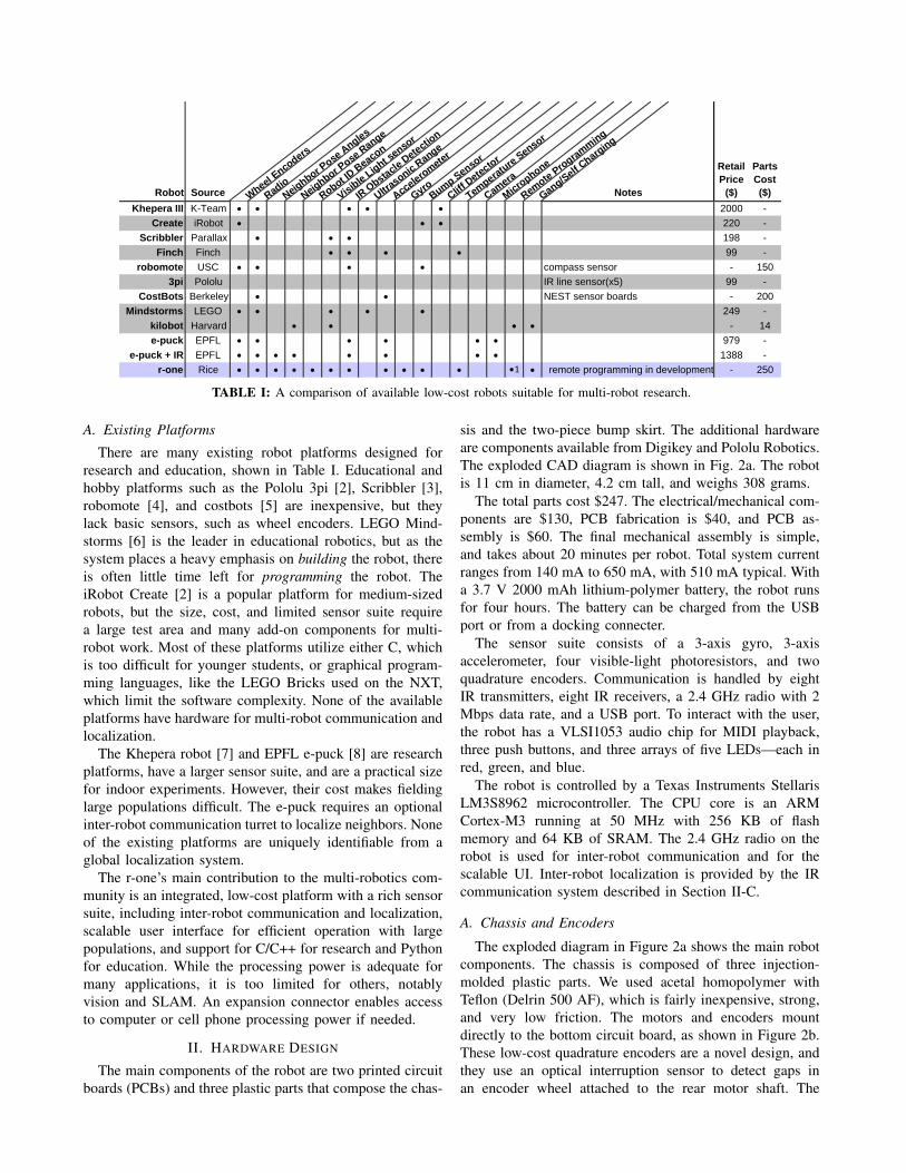
TABLE I: A comparison of available low-cost robots suitable for multi-robot research.
A. Existing Platforms
There are many existing robot platforms designed forresearch and education, shown in Table I. Educational andhobby platforms such as the Pololu 3pi [2], Scribbler [3],robomote [4], and costbots [5] are inexpensive, but theylack basic sensors, such as wheel encoders. LEGO Mind-storms [6] is the leader in educational robotics, but as thesystem places a heavy emphasis on building the robot, thereis often little time left for programming the robot. TheiRobot Create [2] is a popular platform for medium-sizedrobots, but the size, cost, and limited sensor suite requirea large test area and many add-on components for multi-robot work. Most of these platforms utilize either C, whichis too difficult for younger students, or graphical program-ming languages, like the LEGO Bricks used on the NXT,which limit the software complexity. None of the availableplatforms have hardware for multi-robot communication andlocalization.
The Khepera robot [7] and EPFL e-puck [8] are researchplatforms, have a larger sensor suite, and are a practical sizefor indoor experiments. However, their cost makes fieldinglarge populations difficult. The e-puck requires an optionalinter-robot communication turret to localize neighbors. Noneof the existing platforms are uniquely identifiable from aglobal localization system.
The r-one’s main contribution to the multi-robotics com-munity is an integrated, low-cost platform with a rich sensorsuite, including inter-robot communication and localization,scalable user interface for efficient operation with largepopulations, and support for C/C++ for research and Pythonfor education. While the processing power is adequate formany applications, it is too limited for others, notablyvision and SLAM. An expansion connector enables accessto computer or cell phone processing power if needed.
II. HARDWARE DESIGN
The main components of the robot are two printed circuitboards (PCBs) and three plastic parts that compose the chas-
sis and the two-piece bump skirt. The additional hardwareare components available from Digikey and Pololu Robotics.The exploded CAD diagram is shown in Fig. 2a. The robotis 11 cm in diameter, 4.2 cm tall, and weighs 308 grams.
The total parts cost $247. The electrical/mechanical com-ponents are $130, PCB fabrication is $40, and PCB as-sembly is $60. The final mechanical assembly is simple,and takes about 20 minutes per robot. Total system currentranges from 140 mA to 650 mA, with 510 mA typical. Witha 3.7 V 2000 mAh lithium-polymer battery, the robot runsfor four hours. The battery can be charged from the USBport or from a docking connecter.
The sensor suite consists of a 3-axis gyro, 3-axisaccelerometer, four visible-light photoresistors, and twoquadrature encoders. Communication is handled by eightIR transmitters, eight IR receivers, a 2.4 GHz radio with 2Mbps data rate, and a USB port. To interact with the user,the robot has a VLSI1053 audio chip for MIDI playback,three push buttons, and three arrays of five LEDs—each inred, green, and blue.
The robot is controlled by a Texas Instruments StellarisLM3S8962 microcontroller. The CPU core is an ARMCortex-M3 running at 50 MHz with 256 KB of flashmemory and 64 KB of SRAM. The 2.4 GHz radio on therobot is used for inter-robot communication and for thescalable UI. Inter-robot localization is provided by the IRcommunication system described in Section II-C.
A. Chassis and Encoders
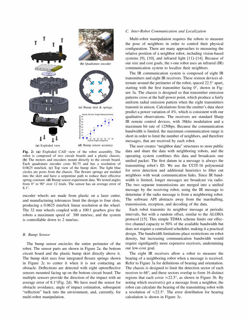
The exploded diagram in Figure 2a shows the main robotcomponents. The chassis is composed of three injection-molded plastic parts. We used acetal homopolymer withTeflon (Delrin 500 AF), which is fairly inexpensive, strong,and very low friction. The motors and encoders mountdirectly to the bottom circuit board, as shown in Figure 2b.These low-cost quadrature encoders are a novel design, andthey use an optical interruption sensor to detect gaps inan encoder wheel attached to the rear motor shaft. The
(a) Exploded view
(b) Quadrature encoder
(c) Bump skirt & springs
0 10 20 30 40 50 60 70 800
10
20
30
40
50
60
70
80
Actual Angle (Degrees)
Mea
sure
d A
ngle
(D
egre
es) Bump Sensor Angle Measurements
Student Version of MATLAB
(d) Bump sensor accuracy
Fig. 2: (a) Exploded CAD view of the robot assembly. Therobot is composed of two circuit boards and a plastic chassis.(b) The motors and encoders mount directly to the circuit board.Each quadrature encoder costs $0.75 and has a resolution of0.0625 mm/tick. (c) Top view of the bump skirt. The light bluecircles are posts from the chassis. The flexure springs are moldedinto the skirt and have a serpentine path to reduce their effectivespring constant. (d) Bump sensor experiment data. We tested anglesfrom 0° to 90° over 12 trials. The sensor has an average error of8.1°.
encoder wheels are made from plastic on a laser cutter,and manufacturing tolerances limit the design to four slots,producing a 0.0625 mm/tick linear resolution at the wheel.The 32 mm wheels coupled with a 100:1 gearbox give therobots a maximum speed of 300 mm/sec, and the systemis controllable down to 2 mm/sec.
B. Bump Sensor
The bump sensor encircles the entire perimeter of therobot. The sensor parts are shown in Figure 2a: the bottomcircuit board and the plastic bump skirt directly above it.The bump skirt uses four integrated flexure springs shownin Figure 2c to center it when it is not contacting anobstacle. Deflections are detected with eight optoreflectivesensors mounted facing up on the bottom circuit board. Themultiple sensors provide the direction of the impact with anaverage error of 8.1°(Fig. 2d). We have used the sensor forobstacle avoidance, angle of impact estimation, subsequent“reflection” back into the environment, and, currently, formulti-robot manipulation.
C. Inter-Robot Communication and Localization
Multi-robot manipulation requires the robots to measurethe pose of neighbors in order to control their physicalconfiguration. There are many approaches to measuring therelative position of a neighbor robot, including vision-basedsystems [9], [10], and infrared light [11]–[14]. Because ofour size and cost goals, the r-one robot uses an infrared (IR)communication system to localize their neighbors.
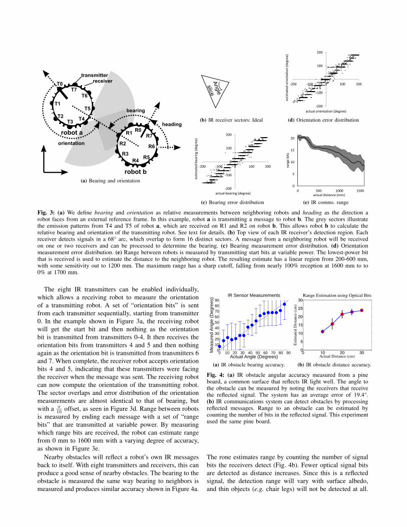
The IR communication system is composed of eight IRtransmitters and eight IR receivers. These sixteen devices al-ternate around the perimeter of the robot, spaced 22.5° apart,starting with the first transmitter facing 0°, shown in Fig-ure 3a. The chassis is designed so that transmitter emissionpatterns cross at the half-power point, which produce a fairlyuniform radial emission pattern when the eight transmitterstransmit in unison. Calculations from the emitter’s data sheetpredict a power variation of 4%, which is consistent with ourqualitative observations. The receivers are standard SharpIR remote control devices, with 38khz modulation and amaximum bit rate of 1250bps. Because the communicationbandwidth is limited, the maximum communication range isshort in order to limit the number of neighbors, and thereforemessages, that are received by each robot.
The user creates “neighbor data” structures to store publicdata and share the data with neighboring robots, and theoperating system combines this data and broadcasts oneunified packet. The first datum in a message is always thetransmitting robot’s ID. We use the CCIT-16 polynomialfor error detection and additional heuristics to filter outneighbors with weak communication links. Since IR band-width is limited, longer messages are broadcast via radio.The two separate transmissions are merged into a unifiedmessage by the receiving robot, using the IR message todetermine if the radio message is from a neighboring robot.The software API abstracts away from the marshalling,transmission, reception, and decoding of the data.
Each robot transmits its neighbor message at periodicintervals, but with a random offset, similar to the ALOHAprotocol [15]. This simple TDMA scheme limits our effec-tive channel capacity to 50% of the available bandwidth butdoes not require a centralized scheduler, making it a practicaldesign. The bandwidth limitations place restrictions on robotdensity, but increasing communication bandwidth wouldrequire signifigantly more expensive receivers, underminingour low-cost goal.
The eight IR receivers allow a robot to measure thebearing of a neighboring robot when a message is received.Refer to Figure 3a for definitions of bearing and orientation.The chassis is designed to limit the detection sector of eachreceiver to 68°, and these sectors overlap to form 16 distinctregions that each cover ≈22.5°, as shown in Figure 3b. Bynoting which receiver(s) get a message from a neighbor, therobot can calculate the bearing of the transmitting robot witha resolution of ≈22.5°. The error distribution for bearingcalculation is shown in Figure 3c.
robot a
T0
T4
T5T1
T2T3
T6T7
bearing
orientation
R0R1
R2
R3
R6
R7
R4R5
robot b
heading
transmitterreceiver
(a) Bearing and orientation
Angle
slice
(b) IR receiver sectors: Ideal
-200
-100
0
100
200
-200 -100 0 100 200
esti
mat
ed b
eari
ng
(deg
ree)
actual bearing (degree)
(c) Bearing error distribution
-200
-100
0
100
200
-200 -100 0 100 200
esti
mat
ed
ori
enta
tio
n (d
egre
e)
actual orientation (degree)
(d) Orientation error distribution
0
5
10
15
20
0 500 1000 1500
ran
ge b
its
actual distance (mm)
(e) IR comms. range
Fig. 3: (a) We define bearing and orientation as relative measurements between neighboring robots and heading as the direction arobot faces from an external reference frame. In this example, robot a is transmitting a message to robot b. The grey sectors illustratethe emission patterns from T4 and T5 of robot a, which are received on R1 and R2 on robot b. This allows robot b to calculate therelative bearing and orientation of the transmitting robot. See text for details. (b) Top view of each IR receiver’s detection region. Eachreceiver detects signals in a 68° arc, which overlap to form 16 distinct sectors. A message from a neighboring robot will be receivedon one or two receivers and can be processed to determine the bearing. (c) Bearing measurement error distribution. (d) Orientationmeasurement error distribution. (e) Range between robots is measured by transmitting start bits at variable power. The lowest-power bitthat is received is used to estimate the distance to the neighboring robot. The resulting estimate has a linear region from 200-600 mm,with some sensitivity out to 1200 mm. The maximum range has a sharp cutoff, falling from nearly 100% reception at 1600 mm to to0% at 1700 mm.
The eight IR transmitters can be enabled individually,which allows a receiving robot to measure the orientationof a transmitting robot. A set of “orientation bits” is sentfrom each transmitter sequentially, starting from transmitter0. In the example shown in Figure 3a, the receiving robotwill get the start bit and then nothing as the orientationbit is transmitted from transmitters 0-4. It then receives theorientation bits from transmitters 4 and 5 and then nothingagain as the orientation bit is transmitted from transmitters 6and 7. When complete, the receiver robot accepts orientationbits 4 and 5, indicating that these transmitters were facingthe receiver when the message was sent. The receiving robotcan now compute the orientation of the transmitting robot.The sector overlaps and error distribution of the orientationmeasurements are almost identical to that of bearing, butwith a π
16 offset, as seen in Figure 3d. Range between robotsis measured by ending each message with a set of “rangebits” that are transmitted at variable power. By measuringwhich range bits are received, the robot can estimate rangefrom 0 mm to 1600 mm with a varying degree of accuracy,as shown in Figure 3e.
Nearby obstacles will reflect a robot’s own IR messagesback to itself. With eight transmitters and receivers, this canproduce a good sense of nearby obstacles. The bearing to theobstacle is measured the same way bearing to neighbors ismeasured and produces similar accuracy shown in Figure 4a.
0 10 20 30 40 50 60 70 80 900
102030405060708090
Actual Angle (Degrees)
Mea
sure
d A
ngle
(D
egre
es) IR Sensor Measurements
Student Version of MATLAB
(a) IR obstacle bearing accuracy.
0 10 20 300
5
10
15
20
25
30
Actual Distance (cm)
Estim
ated
Dist
ance
(cm
)Range Estimation using Optical Bits
Student Version of MATLAB
(b) IR obstacle distance accuracy.
Fig. 4: (a) IR obstacle angular accuracy measured from a pineboard, a common surface that reflects IR light well. The angle tothe obstacle can be measured by noting the receivers that receivethe reflected signal. The system has an average error of 19.4°.(b) IR communications system can detect obstacles by processingreflected messages. Range to an obstacle can be estimated bycounting the number of bits in the reflected signal. This experimentused the same pine board.
The rone estimates range by counting the number of signalbits the receivers detect (Fig. 4b). Fewer optical signal bitsare detected as distance increases. Since this is a reflectedsignal, the detection range will vary with surface albedo,and thin objects (e.g. chair legs) will not be detected at all.
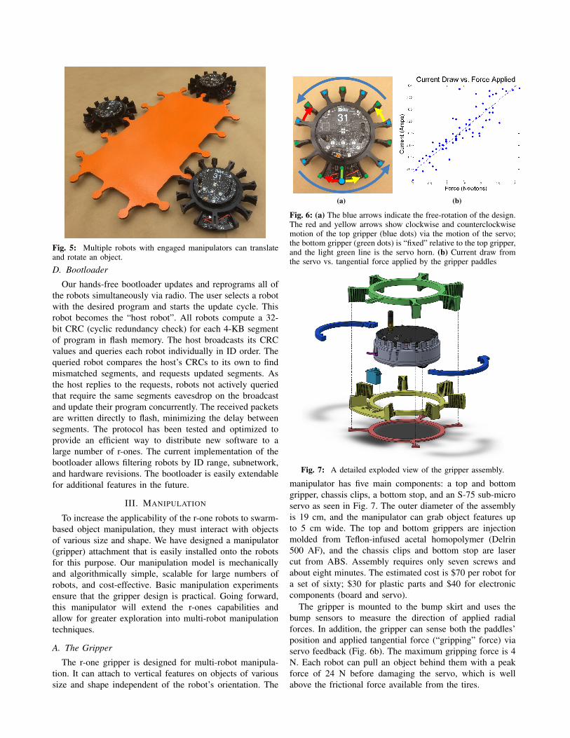
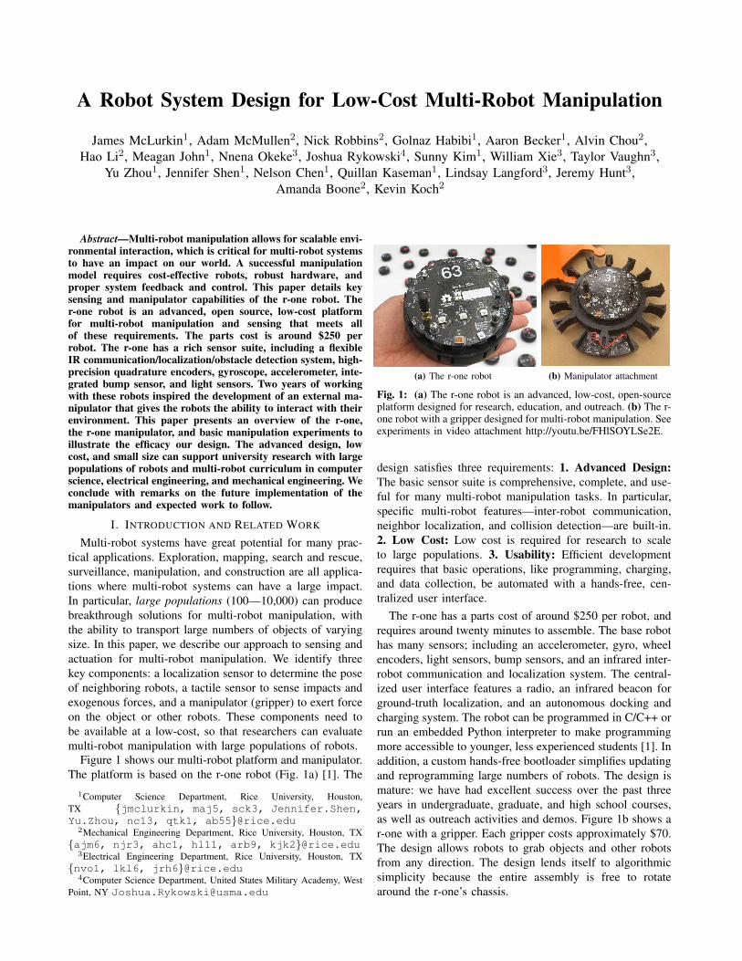
Fig. 5: Multiple robots with engaged manipulators can translateand rotate an object.
D. Bootloader
Our hands-free bootloader updates and reprograms all ofthe robots simultaneously via radio. The user selects a robotwith the desired program and starts the update cycle. Thisrobot becomes the “host robot”. All robots compute a 32-bit CRC (cyclic redundancy check) for each 4-KB segmentof program in flash memory. The host broadcasts its CRCvalues and queries each robot individually in ID order. Thequeried robot compares the host’s CRCs to its own to findmismatched segments, and requests updated segments. Asthe host replies to the requests, robots not actively queriedthat require the same segments eavesdrop on the broadcastand update their program concurrently. The received packetsare written directly to flash, minimizing the delay betweensegments. The protocol has been tested and optimized toprovide an efficient way to distribute new software to alarge number of r-ones. The current implementation of thebootloader allows filtering robots by ID range, subnetwork,and hardware revisions. The bootloader is easily extendablefor additional features in the future.
III. MANIPULATION
To increase the applicability of the r-one robots to swarm-based object manipulation, they must interact with objectsof various size and shape. We have designed a manipulator(gripper) attachment that is easily installed onto the robotsfor this purpose. Our manipulation model is mechanicallyand algorithmically simple, scalable for large numbers ofrobots, and cost-effective. Basic manipulation experimentsensure that the gripper design is practical. Going forward,this manipulator will extend the r-ones capabilities andallow for greater exploration into multi-robot manipulationtechniques.
A. The Gripper
The r-one gripper is designed for multi-robot manipula-tion. It can attach to vertical features on objects of varioussize and shape independent of the robot’s orientation. The
(a) (b)
Fig. 6: (a) The blue arrows indicate the free-rotation of the design.The red and yellow arrows show clockwise and counterclockwisemotion of the top gripper (blue dots) via the motion of the servo;the bottom gripper (green dots) is “fixed” relative to the top gripper,and the light green line is the servo horn. (b) Current draw fromthe servo vs. tangential force applied by the gripper paddles
Fig. 7: A detailed exploded view of the gripper assembly.
manipulator has five main components: a top and bottomgripper, chassis clips, a bottom stop, and an S-75 sub-microservo as seen in Fig. 7. The outer diameter of the assemblyis 19 cm, and the manipulator can grab object features upto 5 cm wide. The top and bottom grippers are injectionmolded from Teflon-infused acetal homopolymer (Delrin500 AF), and the chassis clips and bottom stop are lasercut from ABS. Assembly requires only seven screws andabout eight minutes. The estimated cost is $70 per robot fora set of sixty; $30 for plastic parts and $40 for electroniccomponents (board and servo).
The gripper is mounted to the bump skirt and uses thebump sensors to measure the direction of applied radialforces. In addition, the gripper can sense both the paddles’position and applied tangential force (“gripping” force) viaservo feedback (Fig. 6b). The maximum gripping force is 4N. Each robot can pull an object behind them with a peakforce of 24 N before damaging the servo, which is wellabove the frictional force available from the tires.
0 5 10 15 20 25 300
50
100
150
200
250
300
350
400
time [s]
dist
ance
[mm
]
Best fit, 11.6mm/s
(a) Absolute translation velocities
0 50 100 150
100
200
300
400
500
600
time [s]
head
ing
[Deg
]
Best fit, 2.83Deg/s
(b) Angular velocities about a pivot
0 50 100 1500
50
100
150
200
250
300
350
400
time [s]
head
ing
[Deg
]
databest fit=1.98Deg/sgoal=1.88Deg/s
(c) Angular velocities about an arbitrary point
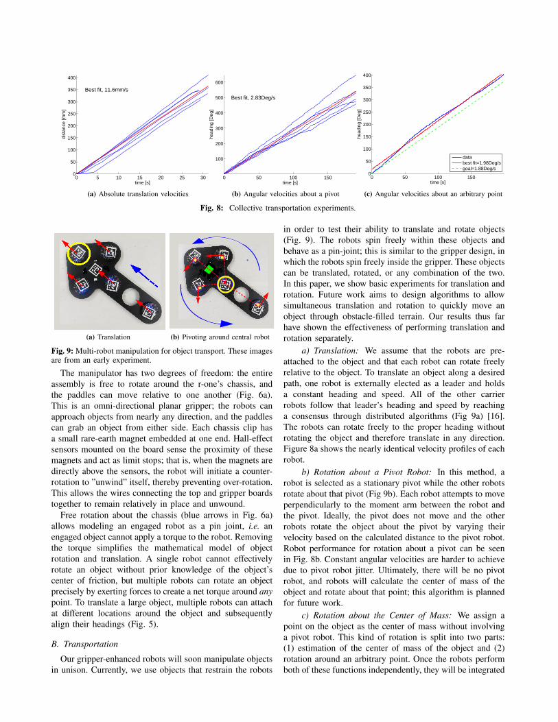
Fig. 8: Collective transportation experiments.
(a) Translation (b) Pivoting around central robot
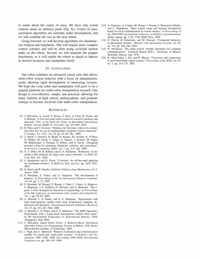
Fig. 9: Multi-robot manipulation for object transport. These imagesare from an early experiment.
The manipulator has two degrees of freedom: the entireassembly is free to rotate around the r-one’s chassis, andthe paddles can move relative to one another (Fig. 6a).This is an omni-directional planar gripper; the robots canapproach objects from nearly any direction, and the paddlescan grab an object from either side. Each chassis clip hasa small rare-earth magnet embedded at one end. Hall-effectsensors mounted on the board sense the proximity of thesemagnets and act as limit stops; that is, when the magnets aredirectly above the sensors, the robot will initiate a counter-rotation to ”unwind” itself, thereby preventing over-rotation.This allows the wires connecting the top and gripper boardstogether to remain relatively in place and unwound.
Free rotation about the chassis (blue arrows in Fig. 6a)allows modeling an engaged robot as a pin joint, i.e. anengaged object cannot apply a torque to the robot. Removingthe torque simplifies the mathematical model of objectrotation and translation. A single robot cannot effectivelyrotate an object without prior knowledge of the object’scenter of friction, but multiple robots can rotate an objectprecisely by exerting forces to create a net torque around anypoint. To translate a large object, multiple robots can attachat different locations around the object and subsequentlyalign their headings (Fig. 5).
B. Transportation
Our gripper-enhanced robots will soon manipulate objectsin unison. Currently, we use objects that restrain the robots
in order to test their ability to translate and rotate objects(Fig. 9). The robots spin freely within these objects andbehave as a pin-joint; this is similar to the gripper design, inwhich the robots spin freely inside the gripper. These objectscan be translated, rotated, or any combination of the two.In this paper, we show basic experiments for translation androtation. Future work aims to design algorithms to allowsimultaneous translation and rotation to quickly move anobject through obstacle-filled terrain. Our results thus farhave shown the effectiveness of performing translation androtation separately.
a) Translation: We assume that the robots are pre-attached to the object and that each robot can rotate freelyrelative to the object. To translate an object along a desiredpath, one robot is externally elected as a leader and holdsa constant heading and speed. All of the other carrierrobots follow that leader’s heading and speed by reachinga consensus through distributed algorithms (Fig 9a) [16].The robots can rotate freely to the proper heading withoutrotating the object and therefore translate in any direction.Figure 8a shows the nearly identical velocity profiles of eachrobot.
b) Rotation about a Pivot Robot: In this method, arobot is selected as a stationary pivot while the other robotsrotate about that pivot (Fig 9b). Each robot attempts to moveperpendicularly to the moment arm between the robot andthe pivot. Ideally, the pivot does not move and the otherrobots rotate the object about the pivot by varying theirvelocity based on the calculated distance to the pivot robot.Robot performance for rotation about a pivot can be seenin Fig. 8b. Constant angular velocities are harder to achievedue to pivot robot jitter. Ultimately, there will be no pivotrobot, and robots will calculate the center of mass of theobject and rotate about that point; this algorithm is plannedfor future work.
c) Rotation about the Center of Mass: We assign apoint on the object as the center of mass without involvinga pivot robot. This kind of rotation is split into two parts:(1) estimation of the center of mass of the object and (2)rotation around an arbitrary point. Once the robots performboth of these functions independently, they will be integrated
to rotate about the center of mass. We have only testedrotation about an arbitrary point (Fig. 8c). Center of massestimation algorithms are currently under development, andwe will combine the two in the near future.
Going forward, we will develop algorithms for simultane-ous rotation and translation. This will require more complexcontrol schemes and will be done using cycloidal motionpaths on the robots. Second, we will integrate the gripperattachment, as it will enable the robots to attach to objectsin desired locations and manipulate freely.
IV. CONCLUSION
Our robot combines an advanced sensor suite that allowsmulti-robot system behavior with a focus on manipulation,easily allowing rapid development of interesting systems.We hope the r-one robot and manipulator will grow to be apopular platform for multi-robot manipulation research. Ourdesign is cost-effective, simple, and practical, allowing formany students in high school, undergraduate, and graduatesettings to become involved with multi-robot manipulation.
REFERENCES
[1] J. McLurkin, A. Lynch, S. Rixner, T. Barr, A. Chou, K. Foster, andS. Bilstein, “A low-cost multi-robot system for research, teaching, andoutreach,” Proc. of the Tenth Int. Symp. on Distributed AutonomousRobotic Systems DARS-10, November, pp. 597–609, 2010.
[2] R. Weiss and I. Overcast, “Finding your bot-mate: criteria for evaluat-ing robot kits for use in undergraduate computer science education,”J. Comput. Sci. Coll., vol. 24, pp. 43–49, Dec. 2009.
[3] T. Balch, J. Summet, D. Blank, D. Kumar, M. Guzdial, K. O’Hara,D. Walker, M. Sweat, C. Gupta, S. Tansley, J. Jackson, M. Gupta,M. Muhammad, S. Prashad, N. Eilbert, and A. Gavin, “Designingpersonal robots for education: Hardware, software, and curriculum,”in Pervasive Computing, IEEE, vol. 7, pp. 5–9, Apr. 2008.
[4] G. T. Sibley, M. H. Rahimi, and G. S. Sukhatme, “Robomote: A tinymobile robot platform for large-scale sensor networks,” in IEEE Int.Conf. Rob. Aut., 2002.
[5] S. Bergbreiter and K. Pister, “Costsbots: An off-the-shelf platformfor distributed robotics,” in IEEE Int. Rob. and Sys., pp. 1632–1637,2003.
[6] D. Baum and R. Zurcher, Definitive Guide to Lego Mindstorms, vol. 2.Apress, 2003.
[7] F. Mondada, E. Franzi, and A. Guignard, “The development ofkhepera,” in Proceedings of the 1st international Khepera workshop,vol. 64, pp. 7–13, 1999.
[8] F. Mondada, M. Bonani, X. Raemy, J. Pugh, C. Cianci, A. Klaptocz,S. Magnenat, J.-C. Zufferey, D. Floreano, and A. Martinoli, “The e-puck, a robot designed for education in engineering,” in Proceedingsof the 9th conference on autonomous robot systems and competitions,vol. 1, pp. 59–65, 2009.
[9] A. Howard, L. E. Parker, and G. S. Sukhatme, “Experiments withlarge heterogeneous mobile robot team: Exploration, mapping, de-ployment and detection,” International Journal of Robotics Research,vol. 25, pp. 431–447, May 2006.
[10] A. Howard, L. E. Parker, and G. S. Sukhatme, “The SDR experience:Experiments with a Large-Scale heterogenous mobile robot team,”in 9th International Symposium on Experimental Robotics 2004,(Singapore), June 2004.
[11] J. McLurkin, Stupid Robot Tricks: A Behavior-Based DistributedAlgorithm Library for Programming Swarms of Robots. S.M. thesis,Massachusetts Institute of Technology, 2004.
[12] J. Pugh and A. Martinoli, “Relative localization and communicationmodule for small-scale multi-robot systems,” in Robotics and Au-tomation, 2006. ICRA 2006. Proceedings 2006 IEEE InternationalConference on, pp. 188–193, 2006.
[13] A. Gutierrez, A. Campo, M. Dorigo, J. Donate, F. Monasterio-Huelin,and L. Magdalena, “Open e-puck range and bearing miniaturizedboard for local communication in swarm robotics,” in Proceedings ofthe 2009 IEEE international conference on Robotics and Automation,(Kobe, Japan), pp. 1745–1750, IEEE Press, 2009.
[14] D. Payton, R. Estkowski, and M. Howard, “Compound behaviorsin pheromone robotics,” Robotics and Autonomous Systems, vol. 44,no. 3-4, pp. 229–240, 2003.
[15] N. Abramson, “The aloha system: Another alternative for computercommunications,” Technical Report B70-1, University of Hawaii,Honolulu, Hawaii, Apr. 1970.
[16] R. Olfati-Saber, J. Fax, and R. Murray, “Consensus and cooperationin networked Multi-Agent systems,” Proceedings of the IEEE, vol. 95,no. 1, pp. 215–233, 2007.