Embed Size (px)
Citation preview
May/Mayıs 2012 Electronic Journal of Vocational Colleges
1
A REVIEW ON THERMAL ENERGY STORAGE SYSTEMS WITH PHASE CHANGE MATERIALS IN VEHICLES
Adem UGURLU1, Cihan GOKCOL2
Abstract
Thermal energy storage (TES) with phase change materials (PCMs) as one of the particular research topics has been paid attention by many researchers. Although the information about this topic is quantitatively enormous, there have not been more studies on its applications in automobiles in literature. There is a great variety of PCMs that can melt and solidify at a wide range of temperatures, making them attractive in a number of applications in automobiles. This paper reviews previous works on TES systems with solid-liquid phase change and provides an insight to recent efforts to develop new types of TES systems with PCMs for use in vehicles. The development of such devices is an extremely urgent need especially for regions with a cold climate. There are three profound aspects to be considered in this study: PCMs, suitable fields for thermal storage in vehicles and some major applications.
Keywords: Phase change materials; Thermal energy storage; Internal combustion engines; Catalytic converters; Evaporator and pressure regulator of LPG
Introduction
Thermal energy storage (TES) systems with phase change materials (PCMs) play important roles in conserving available energy and improving its utilization, since many energy sources are intermittent in nature. Gasoline, diesel, liquefied petroleum gas (LPG), compressed natural gas (CNG) and similar fuels are several of those energy sources, which mostly power internal combustion (IC) engines of today’s vehicles. Some researchers mounted TES systems on automobiles making elimination of numerous negative factors possible. These factors are high fuel consumption, large concentration of carbon monoxide (CO) and hydrocarbon (HC) in exhaust gases, low engine resource time and high load onto accumulator and starter at cold start (Vasiliev et al., 2000; Wentworth, 1968; Boam, 1986; Vasiliev et al., 1999). Reductions of 40 and 50% in unburnt HC and CO, respectively were achieved by Schatz Thermo Engineering Company during a test of a TES system with barium hydroxide as a PCM (Schatz, 1992). Bridgegate Ltd. developed and tested a TES system for BMW 5- series model vehicles. The TES provided 30% reduction in unburnt HC and CO during the engine starting period. The salt mixture of Mg(NO3)H2O and LiNO3 was successfully used as a PCM (Bridgegate, 1996).
Thermal efficiency of IC engines becomes low due to a huge percent of the engine heat loses mostly through the radiator and the exhaust pipe, and partly through engine walls during the engine operation. Furthermore, sunlight is also another source of heat for vehicles in summer. By means of applying an efficient TES application, a productive heat management can be achieved, storing the waste heat and using it later when needed. Such an application provides a considerable energy saving as well as an environmental protection. To do this, first, the waste heat is taken from the coolant and exhaust pipe of the engine as well as sunlight that falls on the vehicle hood or passes through the windows of the car and then is stored. Finally, the stored energy can then be discharged in cold-weather starting to preheat the engine, preheat the catalytic converter, and/or heat-cool the passenger compartment and defrost the car windows. As the TES method has attracted a large number of applications in various fields, vehicle applications will be discussed in this review paper.
1 Öğretim Görevlisi, Kırklareli Üniversitesi, [email protected] 2 Öğretim Görevlisi, Kırklareli Üniversitesi, [email protected]
Electronic Journal of Vocational Colleges May/Mayıs 2012
2
Phase change materials
In the automotive industry, PCMs are used in cooling of engines (Malatidis, 1988), thermal comfort in vehicles (Blüher, 1991), pre-heating of catalytic converters (Burch et al., 1995; Burch et al., 1996; Korin et al., 1998), pre-heating of engine (Vasiliev et al., 2000; Vasiliev et al., 1999; Schatz, 1992; Gumus, 2009), pre-heating of evaporator and pressure regulator of a gaseous sequential injection system (Gumus and Ugurlu, 2011), and other applications in internal combustion engines (Boam, 1986; Darkwa et al., 1997). The key component of a TES system is the PCM. While selecting a suitable PCM; there are many criteria such as high latent heat of phase change, appropriate of the working temperature range, high thermal conductivity at solid state, high specific heat capacity at liquid state, good chemical stability and low vapor pressure at working temperature ranges, high density, non-flammability, non-toxic, non-polluting, little volume variation during solidification, minimum thermal storing losses, and reasonable price, which should be taken into consideration (Gumus and Ugurlu, 2011, Felix et al., 2006; Shanmugasundaram et al., 1997; Wang et al., 2008; Zalba et al., 2003; Korin et al., 1999). PCMs that have been used in vehicle applications for latent heat storage covering a wide range of temperatures are given in Table 1.
Depending on the applications, the PCMs should be selected based on their melting temperature first. Materials that melt below 15 °C are used for storing coolness in air conditioning applications, while materials that melt nearly above 20 °C are used for storing warmness in pre-heating applications (Farid et al., 2004). For catalytic converter applications, over 200 °C of melting temperature could be esteemed to be absolutely necessary, due to high operating temperature range of catalysts. So, the melting temperature of PCMs to be used in TES applications in vehicles is a decisive factor in selecting PCMs.
Table 1. Basic properties of some PCMs which can be applied in vehicle applications as TES materials.
Compound Melting temp. (°C)
Heat of fusion (kJ/kg)
Thermal conductivity (W/m K)
Density (in liquid phase) (kg/m3)
Reference
H2O 0 333 0.612 998 (Zalba et al., 2003)
LiClO3 3H2O 8.1 253 n.a. 1720 (Zalba et al., 2003)
ZnCl2 3H2O 10 n.a. n.a. n.a. (Zalba et al., 2003)
K2HPO4 6H2O 13 n.a. n.a. n.a. (Zalba et al., 2003)
Na2CrO4 10H2O 18 n.a. n.a. n.a. (Zalba et al., 2003)
KF 4H2O 18.5 231 n.a. 1447 (Zalba et al., 2003)
Mn(NO3)2 6H2O 25.8 125.9 n.a. 1738 (Zalba et al., 2003)
Na2SO4 10H2O 32.4 254 0.544 1485 (Gumus and Ugurlu, 2011)
LiNO3 3H2O 30 n.a. n.a. 296 (Gumus and Ugurlu, 2011)
Na2CO3 12H2O 34 246.5 n.a. 1442 (Gumus and Ugurlu, 2011)
(NO3)2 6H2O 36 147 0.464 147 (Gumus and Ugurlu, 2011)
Na2HPO4 12H2O 36 265 n.a. 1522 (Gumus and Ugurlu, 2011)
CaCl2 6H2O 29 187.5 0.538 1560 (Gumus and Ugurlu, 2011)
Ba(OH)2 8H2O 48 265.7 0.653 1937 (Gumus and Ugurlu, 2011)
NaOH H2O 58 n.a. n.a. n.a. (Gumus, 2009)
Cd(NO3)2 4H2O 59.5 n.a. n.a. n.a. (Zalba et al., 2003)
Fe(NO3)2 6H2O 60 n.a. n.a. n.a. (Zalba et al., 2003)
(NaOH) 64,3 227.6 n.a. 1690 (Gumus and Ugurlu, 2011)
May/Mayıs 2012 Electronic Journal of Vocational Colleges
3
Na2B4O7 10H2O 68.1 n.a. n.a. n.a. (Zalba et al., 2003)
Na3PO4 12H2O 69 n.a. n.a. n.a. (Zalba et al., 2003)
Na2P2O7 10H2O 70 184 n.a. n.a. (Zalba et al., 2003)
Ba(OH)2 8H2O 78 265.7 0.653 1937 (Zalba et al., 2003)
Mg(NO3)2 6H2O 89 162.8 0.490 1550 (Zalba et al., 2003)
(NH4)Al(SO4) 6H2O 95 269 n.a. n.a. (Zalba et al., 2003)
MgCl2 6H2O 117 168.6 0.570 1450 (Zalba et al., 2003)
LiNO3 253 389 n.a. 1780 (Korin et al., 1999)
NaNO3 307 176 n.a. 1920 (Korin et al., 1999)
ZnCl2 318 180 n.a. 2540 (Korin et al., 1999)
KNO3 337 96 n.a. 1870 (Korin et al., 1999)
KOH 380 149 0.500 2044 (Gumus, 2009)
MgCl2 714 452 n.a. 2140 (Zalba et al., 2003)
NaCl 800 492 5 2160 (Zalba et al., 2003)
Na2CO3 854 275.7 2 2533 (Zalba et al., 2003)
KF 857 452 n.a. 2370 (Zalba et al., 2003)
K2CO3 897 235.8 2 2290 (Zalba et al., 2003)
n.a.: not available.
TES systems in which PCMs will be used should have also some necessary criteria, such as; high heat capacity, minimum thermal storage losses, comparatively small dimensions and mass, vibration resistant design to satisfy the conditions of the engine operation and compatibility with the environment (Vasiliev et al., 2000). Those systems works on the basis of rejection and absorption of latent heat of the phase change material.
Suitable fields for thermal storage in vehicles
Thermal storage can be used for various fields in vehicles. A TES system takes waste heat (charging) from the engine coolant or exhaust gases during operation and stores about 300 to 13000 kJ energy for hours or days. Sunlight that falls on the vehicle hood or passes through the windows of the car is also another storage source for automobiles in daytime especially in summer. Various methods to store this kind of energy and use it when needed have been tried and used so far. The most common system stores energy by use of a liquid-solid phase change occurring in a water-salt crystal mixture. The stored energy can then be used (discharging) in cold-weather starting to preheat the engine, preheat the catalytic converter, and/or heat-cool the passenger compartment and defrost the car windows (Pulkrabek, 1997).
Most TES systems in vehicles are used for pre-heating of engine, have a mass of about 10-65 kg and can supply 3000-15000 kJ as their temperature drops from 78°C to 30°C. Total energy depletion will normally take 20-30 minutes, depending on the engine and surrounding temperatures. The TES system can be located either in the engine compartment or somewhere else in the automobile, like the trunk. Mounting in the engine compartment results in the least piping and greatest efficiency, but space limitations may not allow this (Pulkrabek, 1997).
Emissions from limited-range dual-powered automobiles that are being developed for city commuting will be greatly reduced with thermal storage. These automobiles, which are propelled by electric motors most of the time and only use their small IC engines when extra power or range is needed, operate their engines in
Electronic Journal of Vocational Colleges May/Mayıs 2012
4
on-off mode. The engine is started only when needed and therefore operates most often only for short periods of time after startup, a highly polluting method. With a TES system, energy can be stored while the engine operates and then used to preheat the engine before the next startup. Although there is no direct running cost in charging a TES system, there will be a very slight cost in higher fuel consumption due to the added mass of the vehicle contributed by the TES. A 10-kg TES system is only 1% of the mass in a 1000 kg automobile. This will cause a very slight steady-state increase in fuel consumption even on long-distance travel. TES systems are designed to last the lifetime of the automobile (Pulkrabek, 1997).
The greatest benefit from TES systems will probably be in those automobiles that are used for city driving. Many city trips are short enough that the catalytic converter never reaches operating temperature, resulting in high exhaust emissions. Reducing startup emissions in densely populated areas is most important because of the large number of automobiles and other polluting systems, as well as the large number of people affected (Pulkrabek, 1997).
Another way the stored energy of a TES system can be used is to pipe the heated coolant through the heat exchanger of the passenger compartment heater system. The heater can then immediately be turned on, with the air flow directed into the passenger compartment and/or onto the windows for deicing. For the first 10 seconds of operation, a TES system can supply 50-100 kW. The system can be started when the ignition key is inserted or even when the car door is opened. Effective preheating occurs within 20-30 seconds. This compares to several minutes for effective heating of the engine, catalytic converter, and passenger compartment on non-preheated automobiles. Various systems supply different percentages of the stored energy and in different sequences to the various uses. Some systems have greater flexibility and changeability than others. Even if all stored energy is delivered to the passenger compartment, the engine will warm up quicker. This is because no engine heat will be diverted to the cabin heater system. This may be important in large trucks as laws are being considered in some areas that require driver compartment heating before the driver is allowed to get into the vehicle. When the TES system is being recharged after the engine has heated up, there is no loss of cabin heater efficiency, the engine supplying more than enough energy for both purposes. (Pulkrabek, 1997)
The use of PCMs to store coolness have been developed for air conditioning applications of buildings, where cold is collected and stored from ambient air during night, and its relieved to the indoor ambient during the hottest hours of the day. This concept is known as free-cooling (Vakilaltojjar et al., 2001; Vakilaltojjar et al., 2000; Bruno et al., 2002). Another application of PCMs in buildings is thermoelectric refrigeration. Omer et al. (Omer et al., 2001; Riffat et al., 2001) have integrated a phase change material in the thermal diode to improve effectiveness of the heat sink. In order to diminish the solar gain in buildings, Ismail et al. (Ismail et al., 2001; Ismail et al., 2002) studied the possibility of using a window with a PCM curtain. This window is double sheeted with a gap between the sheets and an air vent at the top corner; the gap can be filled with PCM that upon freezing would prevent the temperature of the internal ambient from decreasing. Similarly, Merker et al. (Ismail et al., 2001; Ismail et al.,2002) have developed a new PCM-shading system to avoid overheating around the window area (Zalba et al., 2003). All those applications can be imitated to establish thermal comfort of passenger compartments of automobiles exposed to sunlight in summer and/or coolness in winter.
The principle of latent heat storage can be applied to any appropriate vehicle applications.
Some major applications
In this part, some major applications of TES systems with PCMs in vehicles will be dwelled on, and several points that they have will be discussed. Table 2 lists some of those applications found in the literature. As the applications differ from one another, they have been separate from severely on certain points. Readers who are interested in such information are referred to the papers of Vasiliev et al. (Vasiliev et al., 2000), Gumus (Gumus, 2009), Korin et al.( Korin et al., 1999), and Gumus et al.( Gumus and Ugurlu, 2011) who have reported the applications of TES systems with PCMs in various regions of vehicles.
May/Mayıs 2012 Electronic Journal of Vocational Colleges
5
Pre-heating of engines
A preheated engine starts quicker with less wear and wasted fuel. The warmed cylinder walls and intake manifold promote better fuel evaporation, and combustion starts quicker. Also, the over rich intake mixture used to start a cold engine can be lessened, saving fuel and causing less emission. The engine lubricating oil also gets preheated, which greatly reduces its viscosity. This allows for faster engine turnover with the starting motor and quicker engine starting. This also allows for quicker and better early oil distribution, which reduces engine wear (Pulkrabek, 1997).
Table 2. Some major applications found in the literature.
Purpose Dimension
(cm) Material
Quantity (kg)
Melting temp. (°C)
Heat of fusion (kJ/kg)
Charging source
Reference
Pre-heating of an engine
22x22x40 Na2SO4 10H2O 32.5 32.4 254 Engine coolant
(Gumus, 2009)
Pre-heating of an engine
- Ba(OH)28H2O 10 78 320.4 Engine coolant
(Schatz, 1992)
Pre-heating of a bus engine
35x35x50 NaOH H2O with additives
65 64 215 Engine coolant
(Vasiliev et al., 2000)
Pre-heating of a catalytic converter
10x15,3 (dia. x len.)
An eutectic mixture of LiClKCl with additives
3.8 353 251.5 Exhaust gases
(Korin et al., 1999)
Pre-heating of an LPG E&PR of GSI system in a gasoline engine
13,25x10 (dia. x hei.)
Na2HPO412H2O 1.2 36 265 Engine coolant
(Gumus and Ugurlu, 2011)
Extensive efforts have been made to apply the TES method to pre-heating of IC engines, where heat is required to be stored during the engine is turned on for use when the engine is turned off. A number of different TES systems and PCMs have been tried with various successes. One early system uses about 10 kg of Ba(OH)28H2O as the base material. This has a latent heat (solid to liquid) of 320.4 kJ/kg and a melting point of 78°C. The salt-water mixture of this system is contained within hollow fins fastened on the interior of a cylindrical flow chamber through which engine coolant flows. The exterior wall of the cylinder is insulated with super-high vacuum insulation that restricts heat losses to ten kilojoules or less when the surrounding temperature is at -20°C (12,23).
When the engine is running under normal conditions, hot coolant is ducted through the TES system and liquefies the PCM. This is done with energy that would otherwise be rejected in the radiator, so there is no operating cost for the system. When the engine is turned off and coolant flow stops, the liquid-salt solution will very slowly change phase to solid as it cools. This phase change will take about three days because of the super-insulated wall of the container. As the salt solution changes phase, the temperature in the container remains at the near of the melting temperature of the PCM used in the system. To later recover the energy for use in preheating, an electric pump circulates the now cold coolant through the TES system, where it initiates a liquid-back-to solid phase change in the PCM. When this occurs, the latent heat is absorbed by the coolant, which leaves the TES system at a temperature near the solidification starts. The coolant can then be ducted to the engine for preheating. This is possible with proper piping and controls (Pulkrabek, 1997).
Electronic Journal of Vocational Colleges May/Mayıs 2012
6
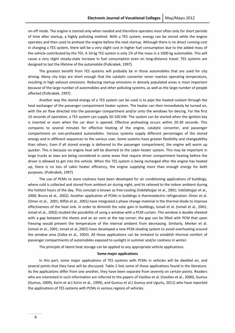
Fig. 1. Schematic of the experimental TES: (1) cover; (2) envelope; (3) capsule containing the PCM; (4) thermal
insulation; (5) outlet pipe; (6) and (7) stainless-steel mesh; (8) entrance pipe. (Vasiliev et al., 2000)
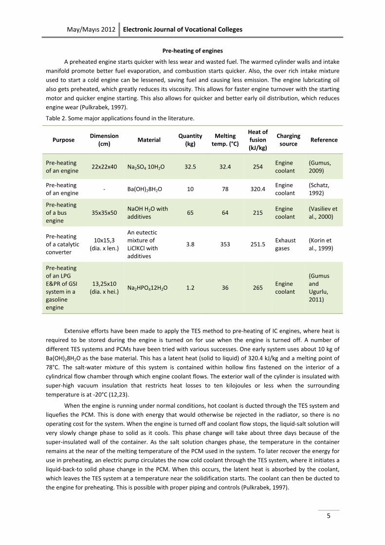
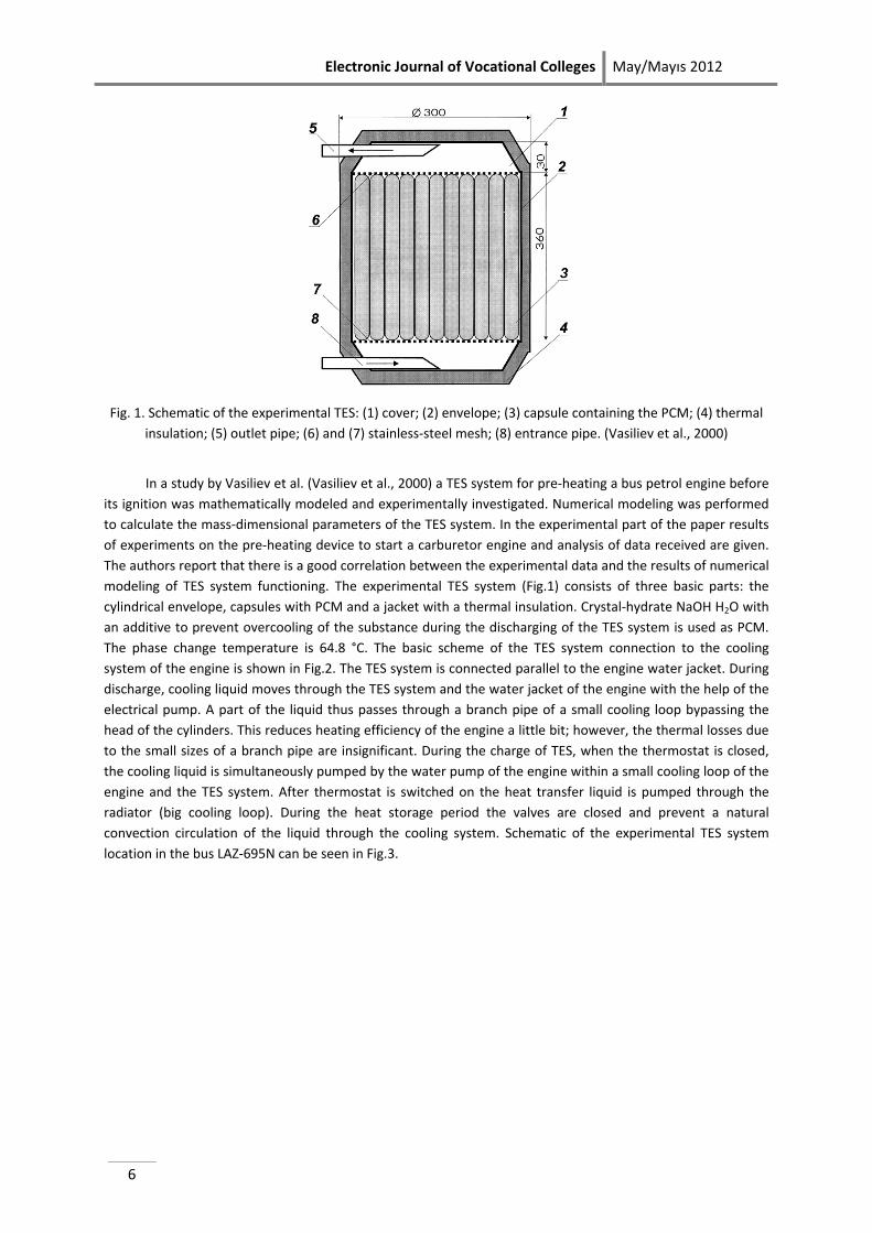
In a study by Vasiliev et al. (Vasiliev et al., 2000) a TES system for pre-heating a bus petrol engine before its ignition was mathematically modeled and experimentally investigated. Numerical modeling was performed to calculate the mass-dimensional parameters of the TES system. In the experimental part of the paper results of experiments on the pre-heating device to start a carburetor engine and analysis of data received are given. The authors report that there is a good correlation between the experimental data and the results of numerical modeling of TES system functioning. The experimental TES system (Fig.1) consists of three basic parts: the cylindrical envelope, capsules with PCM and a jacket with a thermal insulation. Crystal-hydrate NaOH H2O with an additive to prevent overcooling of the substance during the discharging of the TES system is used as PCM. The phase change temperature is 64.8 °C. The basic scheme of the TES system connection to the cooling system of the engine is shown in Fig.2. The TES system is connected parallel to the engine water jacket. During discharge, cooling liquid moves through the TES system and the water jacket of the engine with the help of the electrical pump. A part of the liquid thus passes through a branch pipe of a small cooling loop bypassing the head of the cylinders. This reduces heating efficiency of the engine a little bit; however, the thermal losses due to the small sizes of a branch pipe are insignificant. During the charge of TES, when the thermostat is closed, the cooling liquid is simultaneously pumped by the water pump of the engine within a small cooling loop of the engine and the TES system. After thermostat is switched on the heat transfer liquid is pumped through the radiator (big cooling loop). During the heat storage period the valves are closed and prevent a natural convection circulation of the liquid through the cooling system. Schematic of the experimental TES system location in the bus LAZ-695N can be seen in Fig.3.
May/Mayıs 2012 Electronic Journal of Vocational Colleges
7
Fig.2. Schematic of the TES sytem connection to the cooling system of the engine. (Vasiliev et al., 2000)
Fig.3 . Schematic of the experimental TES system location in the bus LAZ-695N: (1) thermostat; (2) control block of the electrical pump; (3) outlet pipe of TES; (4) TES; (5) valves; (6) electrical pump; (7) union; (8) inlet pipe of
TES; (9) draining valve; (10) T-pipe. (Vasiliev et al., 2000)
Electronic Journal of Vocational Colleges May/Mayıs 2012
8
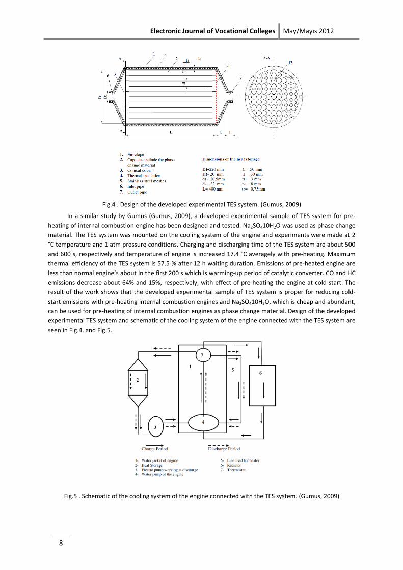
Fig.4 . Design of the developed experimental TES system. (Gumus, 2009)
In a similar study by Gumus (Gumus, 2009), a developed experimental sample of TES system for pre-heating of internal combustion engine has been designed and tested. Na2SO410H2O was used as phase change material. The TES system was mounted on the cooling system of the engine and experiments were made at 2 °C temperature and 1 atm pressure conditions. Charging and discharging time of the TES system are about 500 and 600 s, respectively and temperature of engine is increased 17.4 °C averagely with pre-heating. Maximum thermal efficiency of the TES system is 57.5 % after 12 h waiting duration. Emissions of pre-heated engine are less than normal engine’s about in the first 200 s which is warming-up period of catalytic converter. CO and HC emissions decrease about 64% and 15%, respectively, with effect of pre-heating the engine at cold start. The result of the work shows that the developed experimental sample of TES system is proper for reducing cold-start emissions with pre-heating internal combustion engines and Na2SO410H2O, which is cheap and abundant, can be used for pre-heating of internal combustion engines as phase change material. Design of the developed experimental TES system and schematic of the cooling system of the engine connected with the TES system are seen in Fig.4. and Fig.5.
Fig.5 . Schematic of the cooling system of the engine connected with the TES system. (Gumus, 2009)
May/Mayıs 2012 Electronic Journal of Vocational Colleges
9
Pre-heating of catalytic converters
Under normal operating conditions, catalytic converters appear to be the most effective means of reducing air pollution from IC engines. The conversion efficiency, however, declines very steeply for temperatures below about 350 °C (the exact value depends on the active catalytic material and the particular pollutant component) and is practically zero during the starting and warming-up period. Improving the conversion efficiency under these conditions is important, particularly in large cities, where the number of starting per vehicle per day tends to be high (Korin et al., 1999). Among the more successful solutions are thin wall catalysts, electrically heated catalysts, chemically heated catalyst, electrically initiate chemically heated catalyst, precatalyst method, catalyst surface control method, close-coupled catalyst system (Socha et al., 1998; Kirchner et al., 1996; Golben et al., 1997; Roychoudhury et al., 1997; Karkanis et al., 2003; Jeong et al., 2001; Karthik et al., 2004; Burch et al., 1995; Burch et al., 1996; Korin et al., 1994), heating with an external combustion chamber (Kollman et al., 1994), installing an auxiliary small-capacity catalytic converter (Cooper et al., 1992), employing an adsorber between two catalysts with (Abthoff et al., 1998; Noda et al., 1998) or without a secondary air source (Patil et al., 1998) and using an on-board fuel reformer (Isherwood et al., 1998). Although these methods are quite effective, their disadvantage is that they require an external energy source, a control unit or a three-stage catalyst. An attractive solution to this problem is the incorporation of a phase-change material in the catalytic converter, in combination with an appropriate insulation jacket. With this method, during normal engine operating conditions, some of the thermal energy of the exhaust gases will be stored in the PCM as the material melts. When the engine is not in operation, the PCM will undergo partial solidification, and the released latent heat will be utilized to maintain the catalyst temperature within the desired temperature range. This system will provide suitable conditions for maximum conversion efficiency when the engine is started and warmed up. The unique features of this method are as follows: 1. It is simple to operate, and no active or control means are required. 2. No special energy source is required to heat the converter, since the energy of the exhaust gases from the engine is stored for subsequent use. The main disadvantage of the method is that it is effective only within a specific length of time after the engine has been shut off, the length of time depending on the thermal specifications of the system (Korin et al., 1999).
Exhaust emissions, such as hydrocarbons and carbon monoxide, can be reduced dramatically by up to 80% using a hot converter at the start of the engine. NREL developed a catalytic converter wrapping it using PCMs in compact vacuum insulation to absorb heat of the exhaust gases, keep it at an efficient operating temperature for up to 24 h after the engine is shut off and release as needed (NREL Web Site [www.ctts.nrel.gov/bent]). Preheating the catalytic converter is, therefore, a very productive way of reducing emissions and fuel consumption. This can be done to an extent with a TES system.
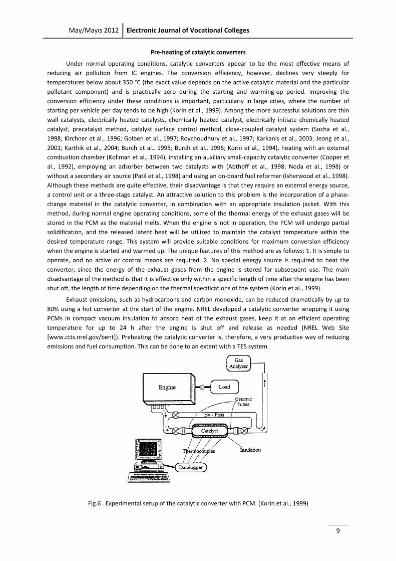
Fig.6 . Experimental setup of the catalytic converter with PCM. (Korin et al., 1999)
Electronic Journal of Vocational Colleges May/Mayıs 2012
10
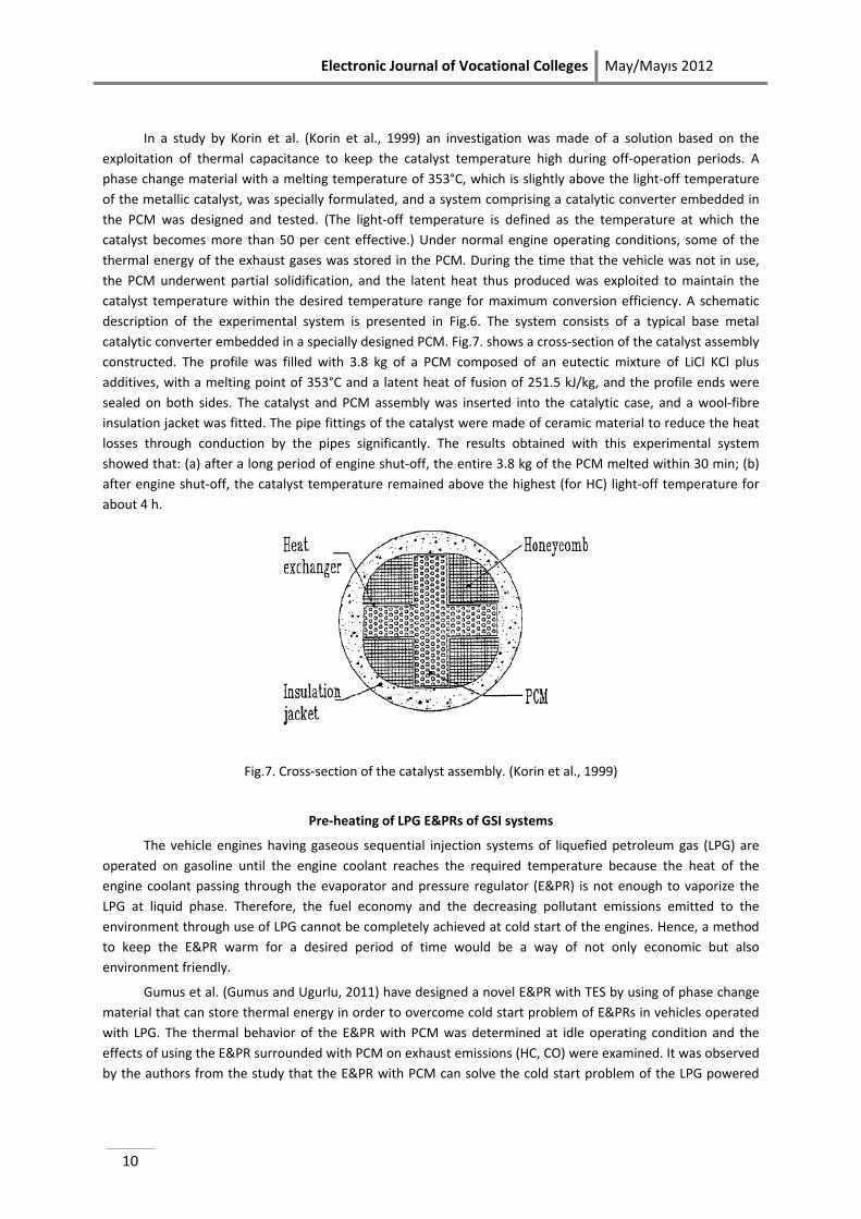
In a study by Korin et al. (Korin et al., 1999) an investigation was made of a solution based on the exploitation of thermal capacitance to keep the catalyst temperature high during off-operation periods. A phase change material with a melting temperature of 353°C, which is slightly above the light-off temperature of the metallic catalyst, was specially formulated, and a system comprising a catalytic converter embedded in the PCM was designed and tested. (The light-off temperature is defined as the temperature at which the catalyst becomes more than 50 per cent effective.) Under normal engine operating conditions, some of the thermal energy of the exhaust gases was stored in the PCM. During the time that the vehicle was not in use, the PCM underwent partial solidification, and the latent heat thus produced was exploited to maintain the catalyst temperature within the desired temperature range for maximum conversion efficiency. A schematic description of the experimental system is presented in Fig.6. The system consists of a typical base metal catalytic converter embedded in a specially designed PCM. Fig.7. shows a cross-section of the catalyst assembly constructed. The profile was filled with 3.8 kg of a PCM composed of an eutectic mixture of LiCl KCl plus additives, with a melting point of 353°C and a latent heat of fusion of 251.5 kJ/kg, and the profile ends were sealed on both sides. The catalyst and PCM assembly was inserted into the catalytic case, and a wool-fibre insulation jacket was fitted. The pipe fittings of the catalyst were made of ceramic material to reduce the heat losses through conduction by the pipes significantly. The results obtained with this experimental system showed that: (a) after a long period of engine shut-off, the entire 3.8 kg of the PCM melted within 30 min; (b) after engine shut-off, the catalyst temperature remained above the highest (for HC) light-off temperature for about 4 h.
Fig.7. Cross-section of the catalyst assembly. (Korin et al., 1999)
Pre-heating of LPG E&PRs of GSI systems
The vehicle engines having gaseous sequential injection systems of liquefied petroleum gas (LPG) are operated on gasoline until the engine coolant reaches the required temperature because the heat of the engine coolant passing through the evaporator and pressure regulator (E&PR) is not enough to vaporize the LPG at liquid phase. Therefore, the fuel economy and the decreasing pollutant emissions emitted to the environment through use of LPG cannot be completely achieved at cold start of the engines. Hence, a method to keep the E&PR warm for a desired period of time would be a way of not only economic but also environment friendly.
Gumus et al. (Gumus and Ugurlu, 2011) have designed a novel E&PR with TES by using of phase change material that can store thermal energy in order to overcome cold start problem of E&PRs in vehicles operated with LPG. The thermal behavior of the E&PR with PCM was determined at idle operating condition and the effects of using the E&PR surrounded with PCM on exhaust emissions (HC, CO) were examined. It was observed by the authors from the study that the E&PR with PCM can solve the cold start problem of the LPG powered
May/Mayıs 2012 Electronic Journal of Vocational Colleges
11
engines. The E&PR surrounded with PCM could start the engine with LPG after the 15 h cooling period of the engine and LPG usage decreased HC and CO emissions by 17.32% and 28.71%, respectively.
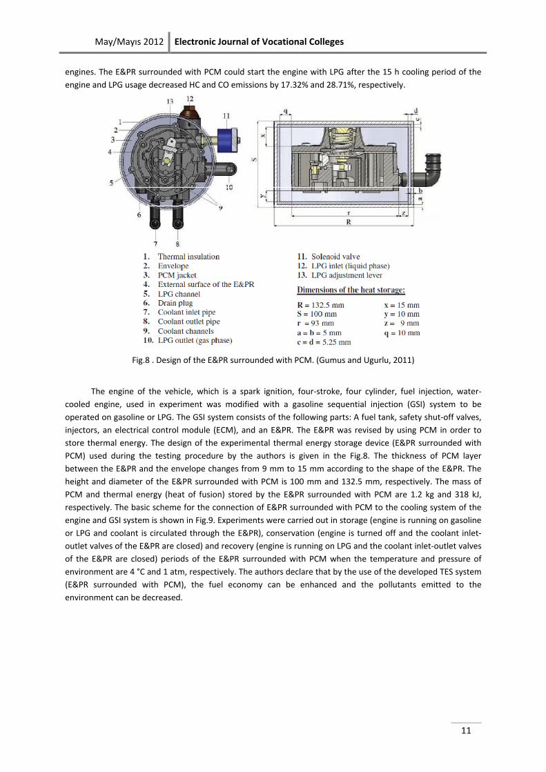
Fig.8 . Design of the E&PR surrounded with PCM. (Gumus and Ugurlu, 2011)
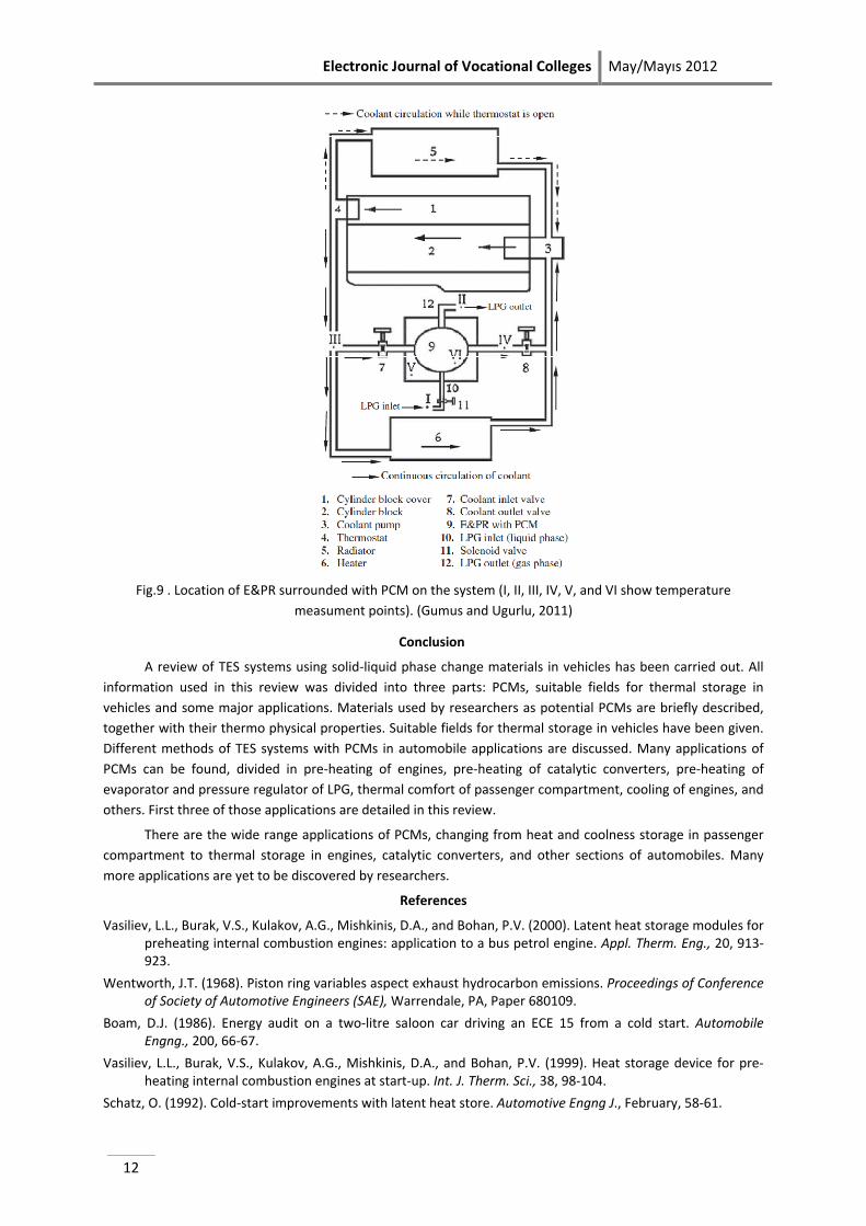
The engine of the vehicle, which is a spark ignition, four-stroke, four cylinder, fuel injection, water-cooled engine, used in experiment was modified with a gasoline sequential injection (GSI) system to be operated on gasoline or LPG. The GSI system consists of the following parts: A fuel tank, safety shut-off valves, injectors, an electrical control module (ECM), and an E&PR. The E&PR was revised by using PCM in order to store thermal energy. The design of the experimental thermal energy storage device (E&PR surrounded with PCM) used during the testing procedure by the authors is given in the Fig.8. The thickness of PCM layer between the E&PR and the envelope changes from 9 mm to 15 mm according to the shape of the E&PR. The height and diameter of the E&PR surrounded with PCM is 100 mm and 132.5 mm, respectively. The mass of PCM and thermal energy (heat of fusion) stored by the E&PR surrounded with PCM are 1.2 kg and 318 kJ, respectively. The basic scheme for the connection of E&PR surrounded with PCM to the cooling system of the engine and GSI system is shown in Fig.9. Experiments were carried out in storage (engine is running on gasoline or LPG and coolant is circulated through the E&PR), conservation (engine is turned off and the coolant inlet-outlet valves of the E&PR are closed) and recovery (engine is running on LPG and the coolant inlet-outlet valves of the E&PR are closed) periods of the E&PR surrounded with PCM when the temperature and pressure of environment are 4 °C and 1 atm, respectively. The authors declare that by the use of the developed TES system (E&PR surrounded with PCM), the fuel economy can be enhanced and the pollutants emitted to the environment can be decreased.
Electronic Journal of Vocational Colleges May/Mayıs 2012
12
Fig.9 . Location of E&PR surrounded with PCM on the system (I, II, III, IV, V, and VI show temperature
measument points). (Gumus and Ugurlu, 2011)
Conclusion
A review of TES systems using solid-liquid phase change materials in vehicles has been carried out. All information used in this review was divided into three parts: PCMs, suitable fields for thermal storage in vehicles and some major applications. Materials used by researchers as potential PCMs are briefly described, together with their thermo physical properties. Suitable fields for thermal storage in vehicles have been given. Different methods of TES systems with PCMs in automobile applications are discussed. Many applications of PCMs can be found, divided in pre-heating of engines, pre-heating of catalytic converters, pre-heating of evaporator and pressure regulator of LPG, thermal comfort of passenger compartment, cooling of engines, and others. First three of those applications are detailed in this review.
There are the wide range applications of PCMs, changing from heat and coolness storage in passenger compartment to thermal storage in engines, catalytic converters, and other sections of automobiles. Many more applications are yet to be discovered by researchers.
References
Vasiliev, L.L., Burak, V.S., Kulakov, A.G., Mishkinis, D.A., and Bohan, P.V. (2000). Latent heat storage modules for preheating internal combustion engines: application to a bus petrol engine. Appl. Therm. Eng., 20, 913-923.
Wentworth, J.T. (1968). Piston ring variables aspect exhaust hydrocarbon emissions. Proceedings of Conference of Society of Automotive Engineers (SAE), Warrendale, PA, Paper 680109.
Boam, D.J. (1986). Energy audit on a two-litre saloon car driving an ECE 15 from a cold start. Automobile Engng., 200, 66-67.
Vasiliev, L.L., Burak, V.S., Kulakov, A.G., Mishkinis, D.A., and Bohan, P.V. (1999). Heat storage device for pre-heating internal combustion engines at start-up. Int. J. Therm. Sci., 38, 98-104.
Schatz, O. (1992). Cold-start improvements with latent heat store. Automotive Engng J., February, 58-61.
May/Mayıs 2012 Electronic Journal of Vocational Colleges
13
Bridgegate Ltd. (Authorized dealership of BMW (GB) Ltd Chesterfield). (1996). Internal technology document, 1- 4.
Malatidis, N. (1988). Warmespeicher insbesondere Latentwarmespeicher für Kraftfahrzeuge. Patent DE 39 90 275 C 1.
Blüher, P. (1991). Latentwarmespeicher erhöht den fahrkomfort und die fahrsicherheit. ATZ Automobiltechnische Zeitschrift, 93, 3-8.
Burch, S.D., Potter, T.F., Keyser, M.A., Brady, M.J., and Michaels, K.F. (1995). Reducing cold start emissions by catalytic converter thermal management. SAE Technical Paper, 950409.
Burch, S.D., Keyser, M.A., Colucci, C.P., Potter, T.F., Benson, D.K., and Biel, J.P. (1996). Applications and benefits of catalytic converter thermal management. SAE Technical Paper, 961134.
Korin, E., Reshef, R., Tsernichovesky, D., and Sher, E. (1998). Improving cold-start functioning of catalytic converters by using phase-change materials. SAE Technical Paper, 980671.
Schatz, O. (1992). Cold-start improvements with latent heat store. SAE Technical Paper, 910305.
Gumus, M. (2009). Reducing cold-start emission from internal combustion engines by means of thermal energy storage system. Appl. Therm. Eng., 29, 652-660.
Gumus, M., and Ugurlu, A. (2011). Application of phase change materials to pre-heating of evaporator and pressure regulator of a gaseous sequential injection system. Applied Energy, 88(12), 4803-4810.
Boam, DJ. (1986). Energy audit on a two-litre saloon car driving an ECE 15 from a cold start. Automob Eng, 200, 66-73.
Darkwa, K., and O’Callaghan, P.W. (1997). Green transport technology (GTT): analytical studies of a thermochemical store for minimizing energy consumption and air pollution from automobile engines. Appl. Therm. Eng., 17, 603-614.
Felix, R.A., Solanki, S.C., and Saini, J.S. (2006). Latent heat thermal energy storage using cylindrical capsule: numerical and experimental investigations. Renew. Energy. 31, 2025-2041.
Shanmugasundaram, V., Brown, J.R., and Yerkes, K.L. (1997). Thermal management of high heat-flux sources using phase change materials: a design optimization procedure. AIAA, 2451-2457.
Wang, X.Q., Yap, C., and Mujumdar, A.S. (2008). A parametric study of phase change material (PCM)-based heat sinks. Int J Therm Sci, 47, 1055-1068.
Zalba, B., Marin, J.M., Cabeza, L.F., and Mehling, H. (2003). Review on thermal energy storage with phase change: materials, heat transfer analysis and applications. Applied Thermal Engineering, 23, 251-283.
Korin, E., Reshef, R., Tshernichovesky, D., and Sher, E. (1999). Reducing cold-start emission from internal combustion engines by means of a catalytic converter embedded in a phase-change material. London: Proceedings of the Institution of Mechanical Engineers.
Farid, M.M., Khudhair, A.M., Razack, S.A.K., and Hallaj, S.A. (2004). A review on phase change energy storage: materials and applications. Energy Convers. Manage., 45, 1597-1615.
Pulkrabek, W.W. (1997). Engineering fundamentals of the internal combustion engine. New Jersey: Prentice Hall.
Vakilaltojjar, S.M., and Saman, W. (2001). Analysis and modelling of a phase change storage system for air conditioning applications. Appl. Thermal Eng., 21, 249-263.
Vakilaltojjar, S.M., and Saman, W. (2000). Domestic heating and cooling with thermal storage. Proceedings of Terrastock 2000, Stuttgart (Germany), 381-386.
Bruno, F., and Saman, W. (2002). Testing of a PCM energy storage system for space heating. Proceedings of the World Renewable Energy Congress WII, Cologne (Germany).
Omer, S.A., Riffat, S.B., and Ma, X. (2001). Experimental investigation of a thermoelectric refrigeration system employing a phase change material integrated with thermal diode (thermosyphons). Appl. Thermal Eng., 21, 1265-1271.
Riffat, S.B., Omer, S.A., and Ma, X. (2001). A novel thermoelectric refrigeration system employing heat pipes and a phase change material: an experimental investigation, Renew. Energy, 23, 313-323.
Ismail, K.A.R., and Henryquez, J.R. (2001). Thermally effective windows with moving phase change material curtains. Appl. Thermal Eng., 21, 1909-1923.
Electronic Journal of Vocational Colleges May/Mayıs 2012
14
Ismail, K.A.R., and Henryquez, J.R. (2002). Parametric study on composite and PCM glass systems. Energy Convers. Mgmt., 43, 973-993.
Merker, O., Hepp, V., Beck, A., and Fricke, J. (2002). A new PCM-shading system: a study of the thermal charging and discharging process. Proceedings of Eurosun 2002, Bologna (Italy).
Merker, O., Hepp, V., Beck, A., and Fricke, J. (2002). A new solar shading system with phase change material (PCM). Proceedings of the World Renewable Energy Congress WII, Cologne (Germany).
Strahle, R., Stephan, B., and Streicher, B. (1997). Heat accumulator for a motor vehicle. Patent WO 97/06972.
Zobel, W., Strahle, R., Stolz, A., Horz, S., Jantschek, T., Van Hoof, H.T.C., De Vuono, A.C., Herrick, R.S., Larrabee, S.R., Logic, J.A., Meissner, A.P., Rogers, J.C., and Voss, M.G. (1999). Heat battery. Patent EP 0 916 918 A2.
Kniep, R. (1995). Latentwarmespeicher in Kraftfahrzeugen. Speichersalze im Blickpunkt, GIT Fachzeischrift faur das Laboratorium, 39, 1137-1141.
Heck, E., Muller, P., and Sebbesse, W. (1994). Latentwarmespeicher zur Verkaurzung des Motorwarmlaufs. MTZ Motortechnische Zeitschrift, 55, 2-8.
Socha, L., Heibel, A., Kessler, B., Rieck, J., Mitchell, G. (1998). Performance of different cell structure converters - a total systems perspective. SAE Technical Paper, 982634.
Kirchner, T., and Eigenberger, G. (1996). Optimization of the cold-start behaviour of automotive catalysts using an electrically heated pre-catalyst. Chem. Eng. Sci., 51, 2409-2418.
Golben, P.M., DaCosta, D., and Sandrock, G. (1997). Hydride based cold-start heater for automotive catalyst. J Alloys Compd, 253, 686-688.
Roychoudhury, S., Muench, G., Bianchi, J., Pfefferie, W., and Gonzales, F. (1997). Development and performance of microlith™ light-off preconverters for LEV/ULEV. SAE Technical Paper, 971023.
Karkanis, A.N., Botsaris, P.N., and Sparis, P.D. (2003). Emission reduction during cold start via catalyst surface control. Proc. Inst. Mech. Eng. Part D - J Automob. Eng., 218, 333-340.
Jeong, S.J., and Kim, W.S. (2001). A new strategy for improving the warm-up performance of a light-off auto-catalyst for reducing cold-start emissions. Proc. Inst. Mech. Eng. Part D - J Automob. Eng., 215, 1179-1196.
Karthik, R., West, D.H., and Balakotaiah, V. (2004). Optimal design of catalytic converters for minimizing cold-start emissions. Catal. Today, 98, 357-373.
Burch, S.D., Potter, T.F., Keyser, M.A., Brady, M.J., and Michaels, K.F. (1995). Reducing cold start emissions by catalytic converter thermal management. SAE Technical Paper, 950409.
Burch, S.D., Keyser, M.A., Colucci, C.P., Potter, T.F., Benson, D.K., and Biel, J.P. (1996). Applications and benefits of catalytic converter thermal management. SAE Technical Paper, 961134.
Korin, E., Reshef, R., Tsernichovesky, D., and Sher, E. (1998). Improving cold-start functioning of catalytic converters by using phase-change materials. SAE Technical Paper, 980671.
Laing, P.M. (1994). Development of an alternator-powered, electrically-heated catalyst system. SAE paper, 941042.
Kollman, K., Abthoff, J., and Zahn, W. (1994). Three-way catalysts for ultra-low-emission vehicles. Automot. Engng., October, 17-22.
Cooper, B. (1992). The future of catalytic systems. Automot. Engng., April, 9-12.
Abthoff, J., Kemmler, R., Klein, H., Matt, M., Robota, H., Wolsing, W., Wiehl, J. and Dunne, S. (1998). Application of in-line hydrocarbon absorber systems. SAE paper, 980422.
Noda, N., Takahashi, A., Shibagaki, Y. and Mizuno, H. (1998). In-line hydrocarbon adsorber for cold start emissions- Part II. SAE paper, 980423.
Patil, M. D., Peng, Y. L. and Morse, K. (1998). Airless in-line adsorber system for reducing cold start HC emissions. SAE paper, 980419.
Isherwood, K. D., Linna, J. R. and Loftus, P. J. (1998). Using on-board fuel reforming by partial oxidation to improve SI engine cold-start performance and emissions. SAE paper, 980939.
NREL Web Site (www.ctts.nrel.gov/bent)