Embed Size (px)
Citation preview
Abstract—Lateral driver support systems have the potential to reduce the number of accidents associated with - both intentional and unintentional - lane departures. Additionally, such systems may increase driving comfort and stimulate a more efficient traffic flow, thereby reducing traffic emissions and the costs associated with traffic delays. This paper provides a literature review to identify the current state of the art on lateral driver support systems. The emphasis is on sensor technology, detection algorithms and safety assessment algorithms.
I. INTRODUCTION UTOMOBILES are undergoing big changes in terms of the new sensor, computer, and communication
technology they incorporate [1]. Systems such as Adaptive Cruise Control (ACC), Lane Departure Warning Assistant (LDWA) and Bind Spot Information System (BLIS) are being introduced on the market. These driver support systems automate parts of the driving task, thereby supporting the driver in safely reaching his or her destination.
According to Smiley [2], human error is the main cause for 90% of all traffic accidents. During many types of collisions, most drivers do not attempt an avoidance maneuver. This suggests that drivers are unaware of the presence of a crash hazard or have recognition failures [3, 4]. Moreover, when drivers are asked why an accident occurred, very often they claim that they saw the other road user too late to avoid a collision [5]. Driver support systems have the potential to reduce the number of traffic accidents associated with human error. Consequently, negative impacts of these accidents (such as injuries, deaths and traffic delays) can be prevented or - at least - mitigated. Additionally, such systems may increase driving comfort, stimulate a more efficient traffic flow, thereby reducing traffic emissions and the costs associated with traffic delays.
Automation, in general, and driver support systems specifically, can be defined as the execution by a machine agent (usually a computer) of a function that was previously carried out by a human [6]. Depending on the amount of
Manuscript received April 4, 2007. M. Tideman is with the Laboratory of Design, Production &
Management, University of Twente, Enschede, The Netherlands (phone: +31 53 489 3192; fax: +31 53 489 3631; e-mail: [email protected]).
M.C. van der Voort is with the Laboratory of Design, Production & Management, University of Twente, Enschede, The Netherlands.
B. van Arem is with Knowledge Centre AIDA, University of Twente, Enschede, The Netherlands.
F. Tillema is with Knowledge Centre AIDA, University of Twente, Enschede, The Netherlands.
tasks and the type of tasks that are automated, automation can be usefully described by a continuum of levels rather than as an all-or-none concept [7]. For example, in describing driver support systems, four different levels can be discerned [3]:
Driver informing systems continuously provide information about the state of the traffic environment. By interpreting this information, the driver is supported in making judgments about the safety of a situation or maneuver;
Driver warning systems generate a warning when some threshold condition is met or exceeded. In contrast to a driver informing system, a driver warning system interprets and assesses the safety of a situation or maneuver. However, the system’s interpretations are meant to enhance the driver’s own interpretations about the traffic environment. The driver’s interpretations dominate the system’s interpretations in the sense that he or she remains fully responsible for the vehicle control task;
Control-intervention systems provide additional cues to the driver for crash avoidance, by imposing vehicle acceleration, deceleration or heading change in the face of a crash hazard. However, the driver will always be able to overrule the actions that were imposed by the system. So just as the driver warning systems, the driver remains fully responsible for the vehicle control task;
Fully automatic control systems involve automatic braking, automatic steering, and automatic throttle control without the possibility for the driver to overrule the system’s actions. The driver’s interpretations about the traffic environment are irrelevant, since there is no means for the driver to overrule the system’s actions.
Apart from a distinction based on the amount of tasks and the type of tasks that are automated, driver support systems can also be classified by the circumstances under which support is provided, the contents of the provided support, the form of the provided support and - if present - the interface that renders the support to the driver. A final distinction often mentioned in literature is the concept of longitudinal support versus the concept of lateral support. Longitudinal support refers to supporting the driver to control the vehicle’s position and velocity in longitudinal (forward or backward) direction, whereas lateral support refers to supporting the driver to control the vehicle’s position and velocity in lateral (sideward) direction.
In 2003, almost 60% of all fatal highway accidents in the USA were caused by lane departures [8]. Most of these accidents originate from unintentional lane departures.
A Review of Lateral Driver Support Systems M. Tideman, M.C. van der Voort, B. van Arem, and F. Tillema, Member, IEEE
A
Proceedings of the 2007 IEEEIntelligent Transportation Systems ConferenceSeattle, WA, USA, Sept. 30 - Oct. 3, 2007
WeC3.4
1-4244-1396-6/07/$25.00 ©2007 IEEE. 992
Researchers estimate that intentional lane departures (i.e. lane change maneuvers) account for 4 to 10% of all crashes in the USA [9]. Lateral driver support systems potentially reduce the number of accidents associated with lane departures, either intentional or unintentional. This paper provides a literature review to identify the current state of the art on lateral driver support systems. The emphasis will be on sensor technology, detection algorithms and safety assessment algorithms.
First, in section II, the system architecture of lateral driver support systems is described. This architecture will serve as a frame of reference throughout the remainder of this paper. Section III focuses on sensor technology used in lateral driver support systems, whereas detection algorithms will be described in section IV. In section V, safety assessment algorithms will be discussed. Finally, section VI contains concluding remarks.
II. SYSTEM ARCHITECTURE
A. Introduction A well-established way of describing the architecture of a
system is according to its functional components. The main function of a lateral driver support system is to support the driver during movements along the lateral axis of the vehicle. This main function can be subdivided into the following three sub-functions:
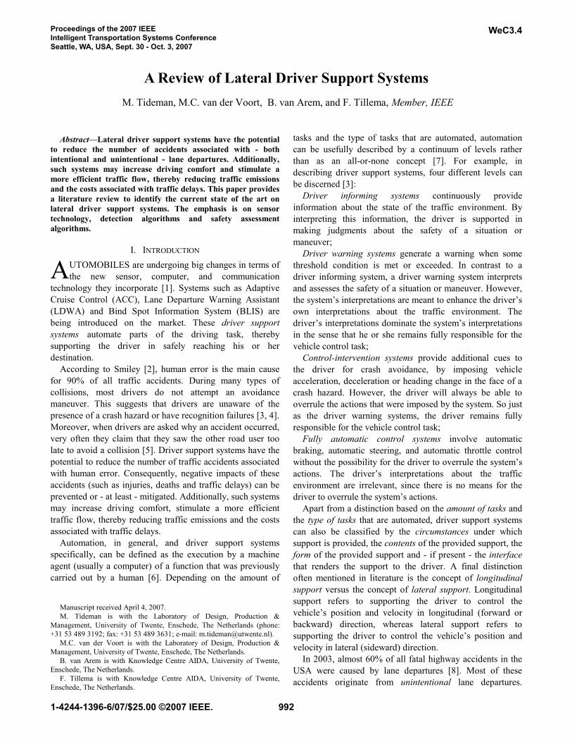
• Sense: to capture information from the context of use1 of a lateral driver support system;
• Think: to interpret this information and to decide what action should be executed;
• Act: to execute this action. These sub-functions can be fulfilled by a wide range of
different hardware and software components. Figure 1 depicts the functional architecture of a lateral support system as well as the most commonly occurring components.
B. Sense Information about the context of use of a lateral driver
support system can be captured by sensors (such as cameras, radar sensors, laser sensors, etc.). Such sensors are used for detecting the traffic environment directly surrounding the vehicle, for example the road and/or other vehicles. Alternatively or additionally, information can be transferred to the vehicle by means of localization networks (such as GPS) and communication networks (such as RDS-TMC, GSM, WLAN, etc.). Such networks usually transfer information that cannot be directly sensed from the vehicle due to an increased distance or due to the presence of obstacles. Finally, other input devices (such as an in-car button for the driver to adjust support system settings) can be 1 A system’s context of use refers to the set of elements that is not part of the system itself, but that may have interactions with the system while using it. The context of use of a lateral driver support system is formed by elements such as driver, vehicle, traffic environment, other road users, etc.
Fig. 1. Lateral driver support system architecture.
993
used for gathering input. Based on all gathered input, detection algorithms determine the context of use.
C. Think Interpreting information that was captured from the
context of use is done by safety assessment algorithms. By comparing the output from the detection algorithms (the determined context of use) with one or more threshold conditions, they may order the actuator control algorithms to execute specific actions.
D. Act In case of support systems where the driver has some
control - the driver informing systems, driver warning systems and control-intervention systems that were mentioned in section I – the action consists of activating one or more human machine interfaces. For example, visual signals rendered on the dashboard panel, auditory signals rendered through the speaker system, tactile signals (vibrations) rendered in the chair, or kinesthetic signals (torques/forces) rendered on the steering wheel or on the pedals. The latter - rendering of kinesthetic signals - coincides with activating vehicle control devices, since there is an active intervention on throttle, brakes and/or the steering system.
In case of fully automatic control systems (see section I), the action always incorporates activation of vehicle control devices. However, as an addition, human machine interfaces may also be activated to inform the driver about the support system’s action.
Alternatively or additionally, information may be broadcasted through communication networks. Finally, other output devices may be activated (for example, switching on the hazard lights to warn drivers of surrounding vehicles).
E. Conclusion As follows from the descriptions in this section - and as
depicted in figure 1 - a lateral driver support system has three sub-functions that can be fulfilled by various different hardware and software components. This review will not discuss every identified component. It will solely consider sensor technology, detection algorithms and safety assessment algorithms that are used within lateral driver support systems. Section III, IV and V will cover these respective subjects.
III. SENSOR TECHNOLOGY
A. Introduction Sensors are used for detecting the traffic environment
directly surrounding the vehicle. For a lateral driver support system, two types of information are most relevant: the position of the vehicle in the lane and the relative positions and velocities of surrounding vehicles and obstacles. Sensors that are capable of fulfilling these tasks can be categorized into active sensors and passive sensors.
B. Active sensors Active sensors emit electromagnetic energy. From the
reflection of this energy, objects can be detected. Moreover, additional information about these objects - such as distance and velocity - can be acquired. Well-known active sensors are radar sensors, laser sensors, sonar sensors and near-infrared sensors. The main advantage of active sensors is that they have the ability to obtain measurements any time, regardless of the time of day or the weather conditions. Additionally, the ability to directly measure certain quantities (distance, velocity) potentially limits required computing power. Drawbacks of active sensors are low spatial resolution, slow scanning speed, size and costs.
C. Passive sensors Passive sensors, on the other hand, detect naturally
reflected or radiated energy. This means that they acquire information in a non-intrusive way. The most well-known passive sensor is the optical sensor (camera). By means of a camera, moving objects (for example vehicles in curves or vehicles moving from one side of the road to the other) can be effectively tracked. Additionally, cameras offer the possibility of lane detection without the necessity to modify the existing infrastructure. A final advantage is that visual information can be helpful for object recognition and identification, for example pedestrian recognition or traffic sign identification. Drawbacks of passive sensors are that they are easily affected by illumination changes as well as by complex environments.
D. Sensor technology in lateral driver support systems Although there are some (prototype) lateral driver support
systems that solely use active sensors, application of passive sensors is most common. Optical sensors are applied for both lane detection and vehicle detection. Apart from using optical sensors, another trend within lateral driver support systems is combining active sensors and passive sensors. In order to give the safety assessment algorithms the proper input, information from these different sensors has to be fused. The next subsections will describe lane detection algorithms and vehicle detection algorithms based on optical sensor information (subsection IV.A and IV.B, respectively). Additionally, vehicle detection algorithms based on sensor fusion will be discussed (subsection IV.C).
IV. DETECTION ALGORITHMS
A. Vision based lane detection Methods for vision based lane (or road edge) detection
can be classified into two categories: feature based methods and model based methods. Feature based lane detection methods make use of lane (or road edge) features. The two most common approaches are based on using grey gradients [10, 11] and on using color patterns [12]. Model based lane detection methods, on the other hand, compare the captured
994
images with road models. Various different techniques (such as Hough transformation, template matching or neural networks) can be applied to detect the lane or road edge [13-15].
B. Vision based vehicle detection 1) Introduction
Methods for vision based vehicle detection need to process captured images at real-time or close to real-time. Locating potential vehicles by searching the entire image is therefore not an option. That is why the majority of methods that are reported in literature follows two basic steps: hypothesis generation (HG) in which the positions of potential vehicles are hypothesized, and hypothesis verification (HV) in which tests are performed to verify the presence of a vehicle in an image.
2) Hypothesis generation (HG) The objective of the HG step is to quickly find candidate
vehicle locations. Methods for HG can be classified into knowledge based, stereo-vision based, and motion based methods.
Knowledge based HG methods employ a-priori knowledge to hypothesize vehicle locations in an image. This knowledge may regard various different vehicle features or properties such as shapes, lights, symmetry, color, shadows, corners, horizontal/vertical edges and textures [16-19].
Stereo-vision based HG methods use depth cues for vehicle detection. There are two types of approaches [20]. One uses disparity maps for vehicle detection, whereas the other uses an anti-perspective transformation (i.e. Inverse Perspective Mapping (IPM)).
Motion based HG methods use the relative motion between objects to distinguish between vehicles and background. Whereas knowledge based HG methods and stereo-vision based HG methods are based on the recognition of spatial features in an image, motion based HG methods are based on the calculation of optical flow [21].
3) Hypothesis verification (HV) The input to the HV step is the set of hypothesized
locations from the HG step. During HV, tests are performed to verify the correctness of a hypothesis. Methods for HV can be classified into template based and appearance based methods [22].
Template based methods use predefined patterns of the vehicle class to verify a correlation between the image and the template [23, 24]. In some approaches, those templates are very ‘loose’, whereas other approaches are based on using very ‘strict’ templates. When using ‘loose’ templates, vehicles that are actually present will always be detected; however, false detections may occur. When using ‘strict’ templates, on the other hand, false detections will only rarely occur. A drawback is that sometimes vehicles will be overlooked.
Appearance based methods use a set of training images that illustrate the variability in vehicle appearance. With this
method, the system ‘learns’ the characteristics of the vehicle class [17, 25]. To improve performance, the variability of the non-vehicle class is usually also trained to the system. The criteria that allow the system to discern the vehicle class from the non-vehicle class can be taught in two ways: by training a classifier (such as a neural network) or by modeling the probability distribution of the features in each class (for example by using the Bayes’ theorem).
C. Vehicle detection based on sensor fusion 1) Introduction
Every sensor type has strong and weak points. Passive sensors are well suited to lane detection as well as vehicle detection. However, their performance strongly depends on illumination conditions. Active sensors, on the other hand, are able to provide accurate distance and velocity information. Additionally, they function at any time of day and under practically any weather condition. However, their performance with regard to object recognition and identification is poor. Moreover, lane detection is practically impossible with this type of sensor.
The concept of sensor fusion is aimed at combining information from different sensors in order to get a more complete picture of the traffic environment and to ensure reliable operation under every circumstance. In theory, sensor fusion can be applied to any combination of two or more sensors. However, as mentioned earlier, optical sensors are practically always present within lateral driver support systems. This subsection gives examples of methods for vehicle detection based on sensor fusion for systems in which at least one optical sensor is present.
2) Fusion of optical and radar sensor information In fusing optical and radar sensor information, some
researchers use a Kalman filter, whereas others use a particle filter [26]. Both filter types use multiple samples of both the optical and the radar sensor information to estimate the locations and velocities of surrounding vehicles. Another approach is to perform initial vehicle detection (hypothesis generation) by using radar information and to come to a final decision (hypothesis verification) based on camera images.
3) Fusion of optical and laser sensor information Bin [27] proposes a method for detecting preceding
vehicles by fusing optical and laser sensor information. Algorithms for hypothesis generation and hypothesis verification (similar to those discussed in sections IV.B.2 and IV.B.3) are employed for the optical sensor information. Simultaneously, the laser sensor also provides an ‘image’ of the environment. Based on the laser sensor information, another distinction is made between the vehicle and the background. The two local processing systems (i.e. the optical processing system and the laser processing system) offer their respective decisions to the fusion centre. Here, the two local decisions are combined into a final decision by using a minimum Bayesian risk fusion rule.
995
4) Fusion of optical and sonar sensor information Kim et al. [28] propose a method to achieve vehicle
detection and tracking by fusing optical and sonar sensor information. They use the sonar sensor for detection and distance estimation for all objects within 10 m of the vehicle and the optical sensor for objects outside the 10 m range. Their system not only functions during daytime, but also at night. By analyzing several camera images, light conditions are determined and based on these light conditions, one of the several detection methods is selected. The daytime vehicle detection method hypothesizes the presence of a vehicle by the shadow of a vehicle on the road. The hypothesis is then verified by using other vehicle features. The night vehicle detection method hypothesizes the presence of a vehicle by bright regions in the image that are caused by the headlights, taillights, and brake lights. In this case, the hypothesis is verified by observing several successive frames.
5) Conclusion As follows from the descriptions in this subsection,
vehicle detection based on sensor fusion for systems in which at least one optical sensor is present can be done in many different ways. This not only refers to the various different possible combinations of sensor types, but also to the fact that the information itself can be fused according to various different methods.
Sensor combinations can be competitive, complementary or cooperative [29]. Competitive sensors each provide equivalent information about the environment (for example, as in the systems described in sections IV.C.2 and IV.C.3). Complementary sensors do not depend on each other directly but can be merged to form a more complete picture of the environment (for example, as in the system described in section IV.C.4). Cooperative sensors work together to derive information that neither sensor alone could provide (for example, as in the stereo-vision system that was described in section IV.B.2). However, until now, there has neither emerged a clear ‘best combination’ of sensor types, nor has there emerged a clear ‘best method’ of sensor fusion for vehicle detection.
V. SAFETY ASSESSMENT ALGORITHMS
A. Introduction As follows from the previous section, detection algorithms
determine the context of use of a lateral driver support system. More specifically, they determine the traffic environment around the vehicle. These determinations form the input for safety assessment algorithms. By continuously comparing the determinations with one or more threshold conditions, such algorithms assess the hazard level of a situation.
In lateral driver support systems, two types of safety assessment algorithms are commonly applied: algorithms for lane departure warning and algorithms for lane change
assistance. Subsections V.B and V.C will discuss these algorithm types.
B. Algorithms for lane departure warning 1) Introduction
The safety assessment algorithms in lane departure warning systems can be classified into three different categories. Algorithms can be based on the vehicle’s current position [30], on the time to line crossing [30-32] or on an interpretation of the road scene [12]. Each of these three categories will be described.
2) Algorithms based on the vehicle’s current position Safety assessment based on the vehicle’s current position
is done by application of equation (1).
−∆++∆−
=∆)2/(2/)2/(2/
vc
vc
bybbyb
y (1)
The distance between the sides of the vehicle and the lane
borders ( y∆ ) is calculated from the lane width ( b ), the lateral offset between the vehicle centre and the lane centre ( cy∆ ), and the vehicle width ( vb ). When 0≥∆y , the vehicle is in its lane and the safety criterion is met. It is considered unsafe when 0<∆y , which means that the vehicle has (partly) left its lane.
To make the algorithm more accurate, personal driving behavior can be taken into account. This can be done by adding a certain ‘personal margin’ to the lane borders. For example, when a driver always maintains a distance of more than 20 cm from the lane borders, those 20 cm are accounted for in the algorithm. In this way, ‘virtual lane borders’ are created. Whenever those virtual lane borders are crossed, the safety assessment algorithm will consider the situation to be unsafe.
3) Algorithms based on the time to line crossing Safety assessment based on the time to line crossing has
the advantage that a possible lane departure is found in a relatively early stage. A vehicle model is used to estimate the moment at which it will leave the lane. There are two types of models that can be applied. The first model assumes that the vehicle will maintain its current heading, whereas the second model assumes that the driver will maintain his or her current steering angle.
Application of the first model gives equation (2):
xyy cc ∆⋅+∆=∆ θ' (2) The predicted lateral offset between the vehicle centre and
the lane centre ( cy'∆ ) is calculated from the actual lateral
offset ( cy∆ ), the actual angle between the vehicle and the
lane (θ ), and the look-ahead distance ( x∆ ). Calculation of
996
the predicted distance between the sides of the vehicle and the lane borders can be done analogous to equation (1).
Application of the second model gives equation (3):
2/' 2xcxyy ccc ∆⋅+∆⋅+∆=∆ θ (3) Compared with equation (2), a term is added that contains
the curvature of the vehicle trajectory ( cc ). This curvature is directly related to the steering angle. Calculation of the predicted distance between the sides of the vehicle and the lane borders can be done in the same way as in equation (1).
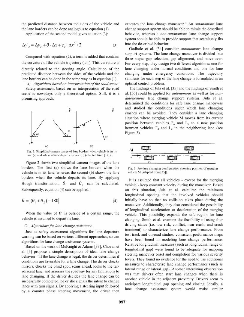
4) Algorithms based on interpretation of the road scene Safety assessment based on an interpretation of the road
scene is nowadays only a theoretical option. Still, it is a promising approach.
Figure 2 shows two simplified camera images of the lane borders. The first (a) shows the lane borders when the vehicle is in its lane, whereas the second (b) shows the lane borders when the vehicle departs its lane. By applying Hough transformation, 1θ and 2θ can be calculated. Subsequently, equation (4) can be applied:
180)( 21 −+= θθθ (4)
When the value of θ is outside of a certain range, the
vehicle is assumed to depart its lane.
C. Algorithms for lane change assistance Just as safety assessment algorithms for lane departure
warning can be based on various different approaches, so can algorithms for lane change assistance systems.
Based on the work of McKnight & Adams [33], Chovan et al. [3] propose a simple description of ideal lane change behavior: “If the lane change is legal, the driver determines if conditions are favorable for a lane change. The driver checks mirrors, checks the blind spot, scans ahead, looks to the far-adjacent lane, and assesses the roadway for any limitations to lane changing. If the driver decides the lane change can be successfully completed, he or she signals the intent to change lanes with turn signals. By applying a steering input followed by a counter phase steering movement, the driver then
executes the lane change maneuver.” An autonomous lane change support system should be able to mimic the described behavior, whereas a non-autonomous lane change support system should be able to provide support that seamlessly fits into the described behavior.
Godbole et al. [34] consider autonomous lane change support systems. The lane change maneuver is divided into three steps: gap selection, gap alignment, and move-over. For every step, they design two different algorithms: one for lane changing under normal conditions and one for lane changing under emergency conditions. The trajectory synthesis for each step of the lane change is formulated as an optimal control problem.
The findings of Jula et al. [35] and the findings of Smith et al. [36] could be applied for autonomous as well as for non-autonomous lane change support systems. Jula et al. determined the conditions for safe lane change maneuvers and studied the conditions under which lane changing crashes can be avoided. They consider a lane changing situation where merging vehicle M moves from its current position between vehicles Fo and Lo to a new position between vehicles Fd and Ld in the neighboring lane (see Figure 3).
It is assumed that all vehicles - except for the merging vehicle - keep constant velocity during the maneuver. Based on this situation, Jula et al. calculate the minimum longitudinal spacing that the involved vehicles should initially have so that no collision takes place during the maneuver. Additionally, they also considered the possibility of longitudinal acceleration or deceleration of the merging vehicle. This possibility expands the safe region for lane changing. Smith et al. examine the feasibility of using four driving states (i.e. low risk, conflict, near crash, and crash imminent) to characterize lane change performance. From test track and on-road studies, consistent performance maps have been found in modeling lane change performance. Relative longitudinal measures (such as longitudinal range or longitudinal gap) were found to be adequate for mapping steering maneuver onset and completion for various severity levels. They found no evidence for the need to use additional measures to characterize lane change performance (such as lateral range or lateral gap). Another interesting observation was that drivers often start lane changes when there is another vehicle in the adjacent proximity. Drivers seem to anticipate longitudinal gap opening and closing. Ideally, a lane change assistance system would make similar
Fig. 3. Pre-lane changing configuration showing position of merging vehicle M (adapted from [35]).
Fig. 2. Simplified camera image of lane borders when vehicle is in its lane (a) and when vehicle departs its lane (b) (adapted from [12]).
997
judgments. However, it is questionable whether future lane change assistance algorithms will be capable of this.
VI. CONCLUSION In 2003, almost 60% of all fatal highway accidents in the
USA were caused by lane departures. Lateral driver support systems could reduce this number. This paper provided a literature review on such systems with a focus on sensor technology, detection algorithms and safety assessment algorithms.
A lateral driver support system requires input about the position of the vehicle relative to the lane and/or input about relative positions and velocities of surrounding vehicles. Sensors that are capable of fulfilling these tasks can be categorized into passive sensors (e.g. optical sensors) and active sensors (e.g. radar, laser, sonar and near-infrared sensors). Passive sensors are well suited to lane detection as well as vehicle detection. However, their performance strongly depends on illumination conditions. Active sensors, on the other hand, are able to provide accurate distance and velocity information. Additionally, they function at any time of day and under practically any weather condition. However, their performance, with regard to object recognition and identification, is poor. Moreover, lane detection is practically impossible. In (prototype) lateral support systems, application of passive sensors is most common. They are used for both lane detection and vehicle detection. Another trend is combining active and passive sensors, for example, a radar sensor and an optical sensor. The concept of sensor fusion is aimed at combining information from different sensors in order to get a more complete picture of the traffic environment and to ensure reliable operation under all circumstances.
We discussed various different detection algorithms - both lane detection and vehicle detection algorithms. Methods for vision based lane detection are either feature based or model based. Methods for vision based vehicle detection are mostly subdivided into two steps: hypothesis generation (HG) and hypothesis verification (HV). During the HG step, candidate vehicle locations are found, whereas during the HV step, tests are performed to verify the correctness of the hypothesized vehicle locations. Just like vision based vehicle detection methods, sensor fusion methods also often function according to the ‘concept of hypothesis generation / hypothesis verification’.
In lateral driver support systems, two types of safety assessment algorithms are commonly applied: algorithms for lane departure warning and algorithms for lane change assistance. Algorithms for lane departure warning can be classified into three different categories. They can be based on the vehicle’s current position, on the time to line crossing, or on an interpretation of the road scene. In practice, the time to line crossing criterion appears to have the best performance in detecting a (possible) lane departure. As far as algorithms for lane change assistance are concerned, a
distinction can be made between algorithms for autonomous and algorithms for non-autonomous lane change support systems. It appears that relative longitudinal gaps are good indicators for the safety of a lane change maneuver. However, human drivers seem to anticipate longitudinal gap opening and closing: they often start lane change maneuvers when there is another vehicle in the adjacent proximity. It is questionable whether future lane change assistance algorithms will be capable of making similar judgments.
ACKNOWLEDGMENT The authors wish to thank visiting scholar Jin Lisheng for
contributing to this article.
REFERENCES [1] Sheridan, T.B. (2004). Driver distraction from a control theory
perspective. Human Factors, vol. 46, no. 4, pp. 587-599. [2] Smiley, A. (1989). Cognitieve vaardigheden van autobestuurders. In:
Knippenberg, C.W.F. van, Rothengatter, J.A., & Michon, J.A. (eds.) (1989). Handboek sociale verkeerskunde. Assen, The Netherlands: Van Gorcum. (in Dutch)
[3] Chovan, J.D., Tijerina, L., Alexander, G., & Hendricks, D.L. (1994). Examination of lane change crashes and potential IVHS countermeasures. Washington DC, USA: NHTSA.
[4] Olsen, E.C.B., Lee, S.E., & Wierwille, W.W. (2005). Eye glance behavior during lane changes and straight-ahead driving. Proceedings of TRB 2005 Annual Meeting.
[5] Rumar, K. (1990). The basic driver error: late detection. Ergonomics, vol. 33, pp. 1281–1290.
[6] Parasuraman, R., & Riley, V. (1997). Humans and automation: use, misuse, disuse, abuse. Human Factors, vol. 39(2), pp. 230-253.
[7] Sheridan, T.B. (1980). Computer control and human alienation. Technology review, 83, pp. 61-70.
[8] Federal Highway Administration (2006). Retrieved October 8th, 2006, from FHWA website: http://safety.fhwa.dot.gov/roadway_dept/index.htm
[9] Lee, S.E., Olsen, E.C.B., & Wierwille, W.W. (2004). A comprehensive examination of naturalistic lane-changes. Washington DC, USA: NHTSA.
[10] Lu Jianye, Yang Ming, Wang Hong, & Zhang Bo (2002). Vision-based real-time road detection in urban traffic. Proceedings SPIE, vol. 4666, pp. 75-82.
[11] Takahashi, A., Ninomiya, Y., Ohta, M., Nishida, M., & Takayama, M. (2002). Rear View Lane Detection by Wide Angle Camera. Proceedings of IEEE Intelligent Vehicles symposium 2002.
[12] Ran, B., & Xianghong Liu, H. (2000). Development of A Vision-Based Real Time Lane Detection and Tracking System for Intelligent Vehicles. Proceedings of Transportation Research Board 79th annual meeting.
[13] Yue Wang, Eam Khwang Teoh, & Dinggang Shen (2004). Lane detection and tracking using B-Snake. Image and Vision Computing, vol. 22(4), pp. 269-280.
[14] Chapuis, R., Laneurit, J., Aufrère, R., Chausse, F., & Chateau, T. (2002). Accurate vision based road tracker. Proceedings of IEEE Intelligent Vehicles symposium 2002.
[15] Gern, A., Moebus, R., & Franke, U. (2002). Vision-based Lane Recognition under Adverse Weather Conditions Using Optical Flow. Proceedings of IEEE Intelligent Vehicles symposium 2002.
[16] Srinivasa, N. (2002). Vision-based Vehicle Detection and Tracking Method for Forward Collision Warning in Automobiles. Proceedings of IEEE Intelligent Vehicles symposium 2002.
[17] Matthews, N., An, P., Chamley, D., & Harris, C. (1996). Vehicle detection and recognition in greyscale imagery. Control Engineering Practice, vol. 4, pp. 473-479.
998
[18] Kalinke, T., Tzomakas, C., & Von Seelen, W. (1998). A Texture-based Object Detection and an adaptive Model-based Classification. Proceedings of IEEE Intelligent Vehicles symposium 1998.
[19] Cucchiara, R., & Piccardi, M. (1999). Vehicle Detection under Day and Night Illumination. Proceedings of ICSC Symposium on Intelligent Industrial Automation 1999.
[20] Zhao, G., & Yuta, S. (1993). Obstacle detection by vision system for autonomous vehicle. Proceedings of IEEE Intelligent Vehicles symposium 1993.
[21] Giachetti, A., Campani, M., & Torre, V. (1998). The use of optical flow for road navigation. IEEE Transactions on Robotics and Automation, vol. 14 (1), pp. 34-48.
[22] Khammari, A., Nashashibi, F., Abramson, Y., & Laurgeau, C. (2005). Vehicle detection combining gradient analysis and AdaBoost classification. Proceedings of IEEE Intelligent Transport Systems 2005.
[23] Sun, Z., Bebis, G., & Miller, R. (2002). On-road vehicle detection using gabor filters and support vector machines. Proceedings of IEEE Conference on Digital Signal Processing 2002.
[24] Handmann, U., Kalinke, T., Tzomakas, C., Werner, M., & Von Seelen, W. (2000). An image processing system for driver assistance. Image and Vision Computing, vol. 18(5), pp. 367-376.
[25] Goerick, C., Noll, D., & Werner, M. (1996). Artificial neural networks in realtime car detection and tracking applications. Pattern Recognition Letters, vol. 17(4), pp. 335-343.
[26] Schweiger, R., Neumann, H., & Ritter, W. (2005). Multiple-cue data fusion with particle filters for vehicle detection in night view automotive applications. Proceedings of IEEE Intelligent Vehicles symposium 2005.
[27] Bin, L.I. (2002). Study on Preceding Vehicle Detection and Safe Headway Control Method of Intelligent Vehicle. PhD Thesis. Changchun College of Transportation, Jilin University, China.
[28] SamYong Kim, Se-Young Oh, JeongKwan Kang, YoungWoo Ryu, Kwangsoo Kim, Sang-Cheol Park, & KyongHa Park (2005). Front and rear vehicle detection and tracking in the day and night times using vision and sonar sensor fusion. Proceedings of IEEE Intelligent Robots and Systems 2005.
[29] Brooks, R.R., & Iyengar, S.S. (1997). Real-Time Distributed Sensor Fusion for Time Critical Sensor Readings. Journal of optical Engineering, vol. 36(3), pp. 767-779.
[30] Risack, R., Moehler, N., & Enkelmann, W. (2000). A video-based lane keeping assistant. Proceedings of IEEE Intelligent Vehicles symposium 2000.
[31] Chen, M., Jochem, T., & Pomerleau, D.A. (1995). AURORA: A vision-based roadway departure warning system. Proceedings of the IEEE Conference on Intelligent Robots and Systems 1995.
[32] Batavia, P.H., Pomerleau, D.A., & Thorpe, C.E. (1998). Predicting lane position for roadway departure prevention. Proceedings of IEEE Intelligent Vehicles symposium 1998.
[33] McKnight, A.J., & Adams, B.B. (1970). Driver education task analysis volume 1: task descriptions. Washington DC, USA: NHTSA.
[34] Godbole, D.N., Hagenmeyer, V., Sengupta, R., & Swaroop, D. (1997). Design of emergency manoeuvres for automated highway system: obstacle avoidance problem. Proceedings of IEEE Decision and Control conference 1997.
[35] Jula, H., Kosmatopoulos, E.B., & Ioannou, P.A. (2000). Collision avoidance analysis for lane changing and merging. IEEE Transactions on Vehicular Technology, vol. 49(6), pp. 2295-2308.
[36] Smith, D.L., Glassco, R., Chang, J., & Cohen, D. (2003). Feasibility of modelling lane-change performance. NHTSA paper 2003-01-0280. Washington DC, USA: NHTSA.
999


![Climate change as a driver of volcano lateral collapse [Bill McGuire]](https://img.pdfslide.us/doc/110x75/558535c0d8b42a30308b5244/climate-change-as-a-driver-of-volcano-lateral-collapse-bill-mcguire.jpg)