Embed Size (px)
Citation preview
UNLIMITED C ndUNCLASSIFIED
LnU)'-U
Ln
Nq A REVIEW OFCRASHWORTHINESS OF
COMPOSITE AIRCRAFTSTRUCTURES
by
C. Poon
National Aeronautical Establishment
et
AERONAUTICAL NOTEOTTAWA NAE-AN-63FEBRUARY 1990 NRC NO. 31276
I .,fcr ptu-' for 1
SNational Research Conseil nationalCouncil Canada de recherches Canada
NATIONAL AERONAUTICAL ESTABLISHMENT
SCIENTIFIC AND TECHNICAL PUBLICATIONS
AERONAUTICAL REPORTS
Aeronautical Reports (LR): Scientific and technical information pertaining to aeronauticsconsidered important, complete, and a lasting contribution to existing knowledge.
Mechanical Engineering Reports (MS): Scientific and technical information pertaining toinvestigations outside aeronautics considered important, complete, and a lasting contribution toexisting knowledge.
AERONAUTICAL NOTES (AN): Information less broad in scope but nevertheless of importanceas a contribution to existing knowledge.
LABORATORY TECHNICAL REPORTS (LTR): Information receiving limited distributionbecause of preliminary data, security classification, proprietary, or other reaons.
Details on the availability of these publications may be obtained from:
Graphics Section,National Research Council Canada,National Aeronautical Establishment,Bldg. M-16, Room 204,Montreal Road,Ottawa, OntarioK1A OR6
ETABLISSEMENT NATIONAL D'AERONAUTIQUE
PUBLICATIONS SCIENTIFIQUES ET TECHNIQUES
RAPPORTS D'AERONAUTIQUE
Rapports d'aeronautique (LR): Informations scientifiques et techniques touchantl'a6ronautique jugdes importantes, completes et durables en termes de contribution auxconnaissances actuelles.
Rapports de genie mecanique (MS): Informations scientifiques et techniques sur larecherche externe A 'adronautique jugdes importantes, compltes et durables en termes decontribution aux connaissances actuelles.
CAHIERS D'AERONAUTIQUE (AN): Informations de moindre portde mais importantes entermes d'accroissement des connaissances.
RAPPORTS TECHNIQUES DE LABORATOIRE (LTR): Informations peu dissdmindes pourdes raisons d'usage secret, de droit de propridt( ou autres ou parce qu'elles constituent des donn6esprdliminaires.
Les publications ci-dessus peuvent ftre obtenues 4 radresse suivante:
Section des graphiques,Qonseil national de recherches Canada,Etablissement national d'adronautique,Im. M-16, pibce 204,Chemin de Montr6al,Ottawa (Ontario)KIA OR6
UNLIMITEDUNCLASSIFIED
A REVIEW OF CRASHWORTHINESS OF COMPOSITE
AIRCRAFT STRUCTURES
ETUDE SUR LA RESISTANCE A L'ECRASEMENT DESSTRUCTURES D'AERONEF EN MATERIAUX COMPOSITES
by/par
C. Poon
National Aeronautical Establishment/Etablissement national d'adronautique
AERONAUTICAL NOTE
OTTAWA NAE-AN-63
FEBRUARY 1990 NRC NO. 31276
W. Wallace, Head/ChefStructures and Materials Laboratory/ G.F. MarstersLaboratoire des structures et mathriaux Director/directeur
SUMMARY
A review of major research activities in North America with respectto the crashworthiness of composite aircraft structures was performed withthe goal of identifying potential Canadian contribution to R&D areas whereeffort would be required to complement the on-going programs in the UnitedStates. e areas reviewed included the crashworthiness design criteria ofthe U.S. y; major experimental programs undertaken by the FAA, theU.S. Army, ASA, and Bell Helicopter Textron Inc. in the U.S., as well asthe UniversitX of Toronto in Canada in developing crashworthiness designconcepts for c posite structures; and the capabilities of crash dynamicscomputer codes.Recommendations include a study on the effect of aircraftsize on crashworthiness design requirements; the implementation of theKRASH code in Canada to establish commonality in analytical methodswith major U.S. and European users; an investigation on the energyabsorption capabilities of the design features for small aircraft containingcomposite and/or composite/hybrid structures; and a parametric studyon the crashworthiness design of composite-to-composite andcomposite-to-metal joints..j' -
RtSUM]k
Une dtude des principales activitds de recherche menses en Am~riquedu Nord sur la resistance A l16crasement des structures d'a~ronef enmateriaux composites a 06 effectude dans le but d'identifier les 6lments departicipation possible du Canada dans les domaines de recherches etd6veloppement ou un effort serait requis pour appuyer les programmesr6guliers des Atats-Unis. Les domaines 6tudids comprennent les critbres deconception de r6sistance A l'dcrasement de I'U.S. Army; d'importantsprogrammes d'expdrimentation entrepris par la FAA, I'U.S. Army, laNASA et Bell Helicopter Textron Inc. aux Etats-Unis, de m~me que parl'University of Toronto au Canada visant A mettre au point des concepts deconception de r6sistance A l'dcrasement pour les structures d'adronef; et lespossibilit6s d'exploitation des codes machines pour le calcul des forcesdynamiques lors de l'crasement. Les recommandations comprennentune 6tude de l'effet de la dimension des a~ro-efs sur les exigences deconception relatives A la resistance A l-cras( , e ,_: l'implantation du codeKRASH au Canada pour uniformiser les me-"s analytiques avec lesprincipaux utilisateurs am6ricains et europdent., ine 6tude des capacitdsd'absorption d'dnergie des caractdristiques de conception des petits sion Foradronefs qui contiennent des structures en matdriaux composites et (ou) encomposites/hybrides; et une analyse param6trique des conceptions de GRA&I 1 "rdsistance A l'6crasement des joints composite sur composite et composite TAB Elsur metal. iounoed
'fIcatio
/ ~.ia'\ Distribution/
Availability CodesK ~ Dis Avail and/or(iii) t Special
/~IniL
TABLE OF CONTENTS
Page
SUMMARY (iii)
LIST OF TABLES (v)
LIST OF FIGURES (v)
LIST OF ABBREVIATIONS (vi)
1.0 INTRODUCTION 1
1.1 Background 11.2 Report Organization 2
2.0 CRASHWORTHINESS DESIGN CRITERIA 2
3.0 ENERGY-ABSORBING COMPOSITE STRUCTURES 3
3.1 FAA Crash Dynamics Program 43.2 Bell Helicopter Textron Inc. (BHTI) Research Programs 53.3 U.S. Army / NASA Research Programs 6
4.0 CRASH SIMULATION OF COMPOSITE STRUCTURES 10
4.1 Computer Code KRASH 104.2 Computer Code DYCAST 114.3 Crash Dynamics Computer Code Developed at UTIAS 13
5.0 CONCLUSIONS AND RECOMMENDATIONS 14
6.0 ACKNOWLEDGEMENT 16
7.0 REFERENCES 16
(iv)
LIST OF TABLES
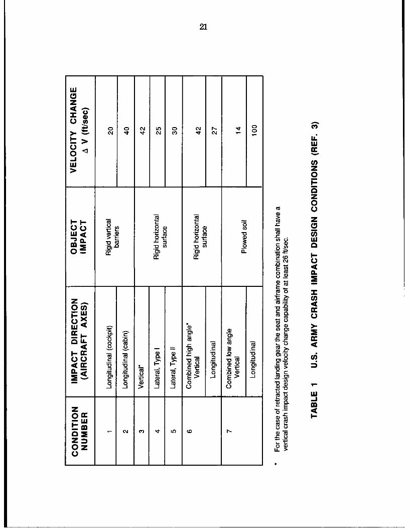
1. U.S. Army Crash Impact Design Conditions .................................................... 21
2. Mechanical Properties of Fiber and Matrix Materials Usedin R eference 15 ....................................................................................................... 22
3. Mechanical Properties of Fiber and Matrix Materials Usedin R eference 16 ....................................................................................................... 22
4. Composite Frame Test Conditions ...................................................................... 23
5. Comparison of Pertinent Features of the Three KRASH Versions ............ 24
6. KRASH Experimental Verifications ................................................................... 25
LIST OF FIGURES
1. Key Parameters for Comparison of Crashworthiness Performance ............ 27
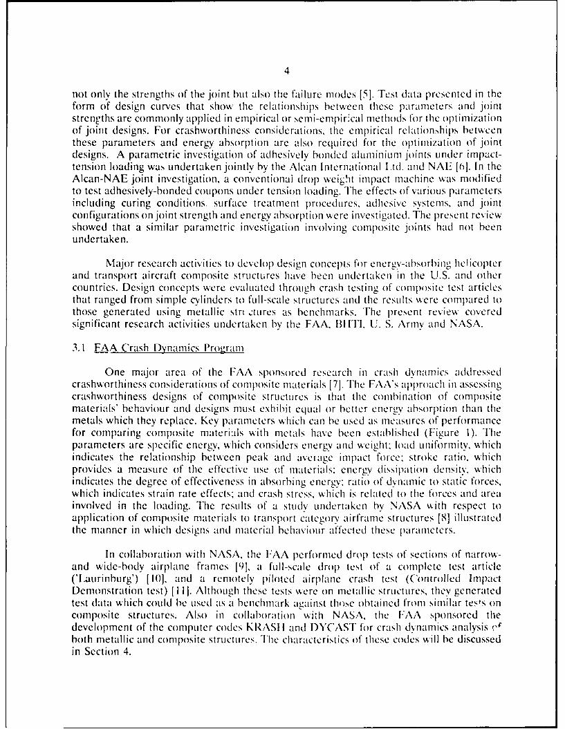
2. Load-Deflection Characteristics of Crushable Subfloor Structurew ith "T riggering D evice". ....................................................................................... 28
3. Effect of Matrix Failure Strain on the Energy Absorption ofGraphite Reinforced Composite Materials ...................................................... 29
4. Energy Absorption of AS4/5245C, AS6/F185 and AS6/HST-7C om posite M aterial ............................................................................................... 30
5. Graphite-Epoxy Z-Shaped Frame Cross Section ............................................... 31
6. Failure Locations for Frames 4 and 5 ................................................................ 32
7. Floor Level Acceleration Pulse for Frames 2 and 5 ......................................... 33
8. Circumferential Flange Strains for Frames 1 and 2 ......................................... 34
9. KRASH and NASTRAN Models of Helicopter Composite Cabin ............... 35
KEYWORDS: Acceleration forces, composite structures, crash impacts,crashworthiness, DYCAST, energy absorption, failure modes,helicopter, KRASH, nonlinearity, post-crash integrity, small aircraft,structural joints, thermoplastics.
(it)
LIST OF ABBREVIATIONS
ACAP Advanced Composite Airframe Program
AVRADCOM Army Aviation Research and Development Command
BHTI Bell Helicopter Textron Inc.
CFE Self-Consistent Finite Element
D/t Inside Diameter to Wall Thickness Ratio
DYCAST Dynamic Crash Analysis of Structures
FAA Federal Aviation Administration
GL/E Glass/Epoxy
GR/E Graphite/Epoxy
K/E Kevlar/Epoxy
LMFE Lump Mass Finite Element
NAE National Aeronautical Establishment
NASA National Aeronautical and Space Administration
NRC National Research Council (Canada)
PEEK Polyetheretherketone
SMI Sypher:Mueller International Inc.
TC Transport Canada
TDC Transportation Development Centre
UTIAS University of Toronto Institute of Aerospace Studies
(vi)
A REVIEW OF CRASHWORTHINESS OF COMPOSITE AIRCRAFT STRUCTURES
1.0 INTRODUCTION
1.1 Background
The Transportation Development Centre (TDC) and the Director of Airworthiness,Transport Canada (TC) commissioned the Sypher:Mueller Inc. (SMI) to review the statusof North American research and development in small aircraft crashworthiness. The objectwas to identify the potential for Canada to play a role in developing crashworthinessrequirements for small aircraft and to develop a comprehensive R&D program which wouldcontribute to the enhancement of the safety of small aircraft. The study was completed inJuly 1987 with the issue of Report TP8655E entitled "Small Aircraft Crashworthiness" bythe TDC [1].
Following he research study, a seminar was held on March 9, 1988 under the jointsponsorship of the TDC and TC. The purpose was to explore the future focus of CanadianR&D activity in small aircraft crashworthiness, to develop a coordinated R&D programbetween government, industry, and the universities, and to enhance the joint R&D activitiesbetween Canada and the U. S. The seminar was attended by all sectors of the CanadianAviation Community, including Transport Canada, National Research Council (NRC),Aerospace Industries Association of Canada, Canadian Aviation Safety Board, Universityof Toronto Institute of Aerospace Studies (UTIAS), Canadian Owners and PilotsAssociation, plus representatives of the United States Federal Aviation Administration(FAA), National Transportation Safety Board, and the General Aviation Manufacturer'sAssociation. Upon the recommendation of the Canadian participants, a Small AeroplaneCrashworthiness R&D Committee was established under the initil's sponsorship of TC andthe National Aeronautical Establishment (NAE)/NRC. The role of the Committee is tocoordinate and advise TC on the conduct of R&D for the improvement of crashworthinessof small aeroplanes which include normal, utility and aerobatic aeroplanes in Canada.
The first meeting of the Committee on June 1, 1988 established a task for SMI todevelop a small aeroplane crashworthiness R&D plan based on the seminar proceedingsand the conclusions and recommendations of the report TP8655E. In the second meetingon August 29, 1989, the Committee approved the draft report "Crashworthiness R&D Plan"prepared by SMI [2]. The report produced a list of five program areas. The program areawith the highest priority dealt with Seats, Harnesses, and Floor Sub-Structures while theprogram area next in priority concerned Composite Materials and Structures. TheCommittee recommended the establishment of a working team consisting of technical staffsfrom TC and NAE to produce work statements in these two program areas. To respond tothe Committee's recommendation, the Structures and Materials Laboratory of NAEinitiated two in-house reviews of the research work performed in these two program areas.This report presents the review of the work done to address the crashworthiness aspects ofcomposite structures.
2
1.2 Report Organization
Most of the work covered in this review was performed in the U.S. under thesponsorships of the FAA, U.S. Army and NASA. This review excluded the historicalevolution of regulatory requirements and development of accident analysis in small aircraftcrashworthiness since these two topics are well covered in Report TP8655E [1].
A general, comprehensive overview of crashworthiness research activities in both theU.S. and Canada is provided in Report TP8655E [1]. This present review attempts to avoidduplications and focuses on technical details of the research activities with respect tocrashworthiness of composite airframe structures. A description of the development of theAircraft Crash Survival Design Guide [3] by Simula Inc. for the U.S. Army and highlightsof crashworthiness design criteria of the MIL-STD-1290A [4] are given in Section 2.Although the criteria discussed are considered significantly more demanding than thoserequired in the Federal Aviation Regulations, they are regarded as extremely valuable indeveloping new crashworthiness standards including those for new materials. Section 3presents an overview of major research activities addressing the energy-absorbingcharacteristics of composite structures. It includes programs undertaken by the FAA, BellHelicopter Textron Inc. (BHTI), U. S. Army and NASA that range from testing of simplecylinders to complex crash testing of full-scale structures. State-of-the-art computer codesthat are capable of crash simulation of composite structures are discussed in Section 4. Thelast section is devoted to conclusions and recommendations.
2.0 CRASHWORTHINESS DESIGN CRITERIA
The Aircraft Crash Survival Design Guide [3] was prepared for the Safety andSurvivability Technical Area of the Applied Technology Laboratory, U.S. Army Researchand Technology Laboratories of the U.S. Army Aviation Research and DevelopmentCommand (AVRADCOM) by Simula Inc. A major portion of the data contained in theDesign Guide was taken from the U.S. Army sponsored research in aircraft crashworthinessconducted from 1960 to 1979. Since its initial publication in 1967, the design guide has beenrevised several times to incorporate the results of continuing research in crashworthinesstechnology. The fourth revision of the Design Guide contains a comprehensive treatmentof all aspects of aircraft crash survival documented up to 1979 and its design criteria wereused to formulate the latest revision of the U.S. Army's aircraft crashworthiness militarystandard MIL-STD-1290A(AV), published in September 26, 1988. Highlights of the designcriteria contained in MIL-STD-1290A(AV) [4] are presented in the following paragraphs.
The goal of a crashworthiness design of an airframe structure is to prevent occupantfataiities and minimize the severity of injuries in survivable crash impacts. Survivable crashimpacts were defined as those in which the forces transmitted to the occupant through theseat and restraint system do not exceed the limits of human tolerance to abruptaccelerations and in which the structure in the occupant's immediate environment remainssubstantially intact to the extent that a livable volume is provided for the occupantsthroughout the crash sequence. Typical Army survivable crash impact conditions are shownin Table 1. To achieve this goal, the airframe must be designed to maintain structural
3
integrity and a livable space for the occupants. The airframe should also be designed topossess high roll-over strength and high retention strength for large mass components. Inorder to minimize the effects of post-crash hazards, the structure should be designed tomaintain the integrity of normal exits for emergency egress and provide protection againstflammable fluid systems.
Energy-absorbing features are required to prevent excessive and injuriousacceleration (G) forces from being transmitted to the occupants under the crash impactconditions given in Table 1. The limits of human tolerance to abrupt accelerations can befound in Volume II of the Aircraft Crash Survival Design Guide [3]. The forward fuselagestructure should be designed to absorb energy during longitudinal impacts and to minimizesoil plowing. In addition, the floor structure must be designed to maintain sufficientstrength througthout the crash to carry the loads applied by occupants, seats and cargorestraint systems. A crushable sub-floor structure should be incorporated to absorb energyin vertical crash impacts. Energy-absorbing seats and proper occupant restraint systemsshould be provided to improve survivability and minimize the severity of injuries. The wingsshould be designed to possess frangible characteristics such that they break free from thefuselage under high impact loads. The landing gear should be designed to provide energyabsorption to reduce the vertical velocity of the fuselage.
In order to satisfy the crashworthiness design criteria discussed, a total systemsapproach which includes a strong protective shell to protect the occupants from crushingas well as energy-absorbing components to prevent injurious G forces must be adopted. Itis important to demonstrate that in replacing metals by composite materials in aircraftstructures, the capability to absorb energy and to maintain post-crash integrity is notcompromised. In the following section, the review is focused on the research activities inthe development of energy-absorbing composite structures which demonstrate compliancewith the crashworthiness design criteria.
3.0 ENERGY-ABSORBING COMPOSITE STRUCTURES
Polymer-based fiber composite materials offer significant benefits over metallicstructures in reducing weight and cost as well as improving fatigue and corrosion resistance.However, these materials exhibit low strain-to-fai',ire ranges compared to such metals as2024 aluminium, a ductile metal that can tolerate rather large strains, deform plastically,and absorb a considerable amount of energy in the nonlinear region without fracture.Because of this difference between metals and composites, crash energy absorption withcomposites must come from innovative design to enhance stress-strain behaviour. Innovativedesign concepts involving notched corners, corrugated and tapered edge joints, and less stifflaminate layups were found to be effective in improving load-deflection characteristics ofcomposite structures.
Assembly operations such as mechanical joining, adhesive bonding, co-curing, andother kinds of attachments contribute to crashworthiness. A further enhancement in energyabsorption and post-crash integrity can be achieved by optimizing the design of joints. Thedesign of composite joints is well known to be influenced by many parameters which affect
4
not only the strengths of the joint hut also the failure modes [51. Test data presented in theform of design curves that show the relationships between these parameters and jointstrengths are commonly applied in empirical or semi-empir:cal methods for the optimizationof joint designs. For crashworthiness considerations, the empirical relation.,,hips betweenthese parameters and energy absorption are also required for the optimization of jointdesigns. A parametric investigation of adhesively bonded aluminiu m joints tinder impact-tension loading was undertaken jointly by the Alcan International Ltd. and NAE [6]. In theAlcan-NAE joint investigation, a conventional drop weight impact machine was modifiedto test adhesively-bonded Coupons Linder tension loading. The effects of various parametersincluding curing conditions. surface treatment procedures, adhesive systems, and jointconfigurations on joint strength and energy absorption were investigated. The present reviewshowed that a similar parametric investigation involving composite joints had not beenundertaken.
Major research activities to develop design concepts for energy-absorbi ng helicopterand transport aircraft composite structures have been undertaken in the U.S. and othercountries. Design concepts were evaluated through crash testing of composite test articlesthat ranged from simple cylinders to full-scale structures and the results were compared tothose generated using metallic stri tures as benchmarks. The present review coveredsignificant research activities undertaken by the FAA, BIITI, U. S. Army and NASA.3.1 FAA Crash Dynamics Program
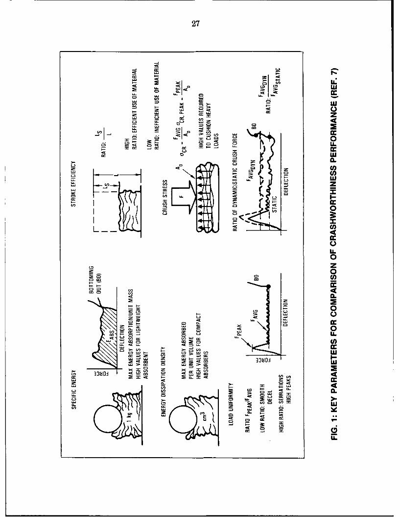
One major area of the FAA sponsored research in crash dynamics addressedcrashworthiness considerations of composite materials [7]. The FAA's approach in assessingcrashworthiness designs of composite structures is that the comb)ination of compositematerials' behaviour and designs must exhibit equal or better energy absorption than themetals which they replace. Key parameters which can be used as measures of performancefor comparing composite materi:als with metals have been established (Figure 1). Theparameters are specific energy, which considers energy and weight; load uniformity, whichindicates the relationship between peak arid average impact force: stroke ratio, whichprovides a measure of the effective use of materials: energy dissipation density, whichindicates the degree of effectiveness in absorbing energy; ratio of dynamic to static forces,which indicates strain rate effects; and crash stress, which is related to the forces and areainvolved in the loading. The results of a study undertaken by NASA w,%ith respect toapplication of composite materials to transport category airframe structures [81 illustratedthe manner in which designs and material behaviour affected these parameters.
In collaboration with NASA, the FAA performed drop tests of sections of narrow-and wide-body airplane frames [9], a full-scale drop test of a complete test article('Uaurinburg') [10], arid a remotely piloted airplane crash test (Controlled ImpactDemonstration test) [II]. Although these tests were on metallic structures, they generatedtest data which could be used as a benchmark against those obtained from similar tests oncomposite structures. Also in collaboration wvith NASA, the FAA sponsored thedevelopment of the computer codes KRASI I and 1)YCAST for crash dynamics analysis (e"both metallic arid composite structures. The characteristics of these codes will be discussedin Section 4.
3.2 Bell Helicopter Textron Inc. (BHTI) Research Programs
In a BttTI in-house research program, initial investigations of the crash impactbehaviour of composite materials were focused on the testing of simple composite cylinders.Crush testing of cylinders made of graphite/epoxy (GR/E), Kevlar/epoxy (K/E), andfiberglass/epoxy (GL/E) was performed by Cronkhite [12] to determine basic compressionfailure modes and energy absorption of these composites. He found that both the GR/Eand GL/E cylinders failed in a brittle fracturing mode while the K/E cylinders failed in aprogressive folding mode much like a ductile metal. The GR/E material showed the highestspecific energy absorption (energy absorbed per pound weight).
The BHTI in-house program continued to investigate various energy-absorbingsu)floor design concepts [13]. Of the concepts investigated, a K/E sandwich structure wasselected for the design and fabrication of crushable subfloors of composite airframes. Thisdecision was based on the results obtained from design-support testing of small keel beamsections which indicated that the K/E sandwich construction demonstrated excellent stroke-to-length ratios of up to 80% before bottoming out, good energy-absorbing and load-limitingability, good post-crushing structural integrity and no significant load rate sensitivity.
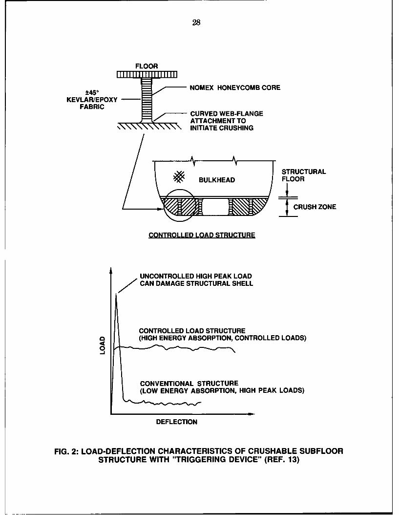
In a contracted R&D program conducted by BHTI for the Applied TechnologyLaboratory of the U.S. Army Research and Technology Laboratories (AVRADCOM), theenergy-absorbing K/E sandwich subfloor structure was incorporated into two full-scalecomposite cabin test sections and drop tested [14J. The floor structure utilized a crushinitiator or "triggering device" to prevent the occurrence of excessive peak loading priorto the onset of controlled-load crushing (see Figure 2). The composite cabins were derivedfrom BHTI's Advanced Composite Airframe Program (ACAP) and were fabricated withK/E, GR/E and GL/E materials. The KRASH computer code was used to design theACAP composite airframe to meet the crashworthiness requirements of the U.S. ArmyMIL-STD-1290 [15]. The requirement for vertical crash impact velocity specified in MIL-STD-1290 is 42 ft/s. Both cabin sections were actually drop tested at 30 ft/s. Since bothcabin sections were not equipped with landing gear, it was justified to adopt a lower dropvelocity by assuming that the landing gear had slowed the aircraft from 42 ft/s to 30 ft/sprior to fuselage contact.
The first cabin section was drop tested at a 30 ft/s vertical impact velocity and at aflat attitude with no pitch or roll. Floor and bulkhead mounted stroking seats andanthropomorphic dummies were installed to study the effects of the crash on a humanoccupant. The second cabin section was impacted at a 20 deg. roll attitude and at the samevelocity as the first test. The dummies and stroking seats were replaced with 177-poundrigid lumped masses in the second drop test. Accelerations of the large masses weremeasured in both drop tests and displacements of the stroking seats were recorded in theflat drop test. In additior, high-speed motion pictures were used to record the cabinstructure response.
Both cabin drop tests successfully demonstrated that the U.S. Army's crashworthinessrequirements could be met by a composite airframe structure based on the excellent post-
6
test condition of the cabins' protective shell structure and the performance of the energy-absorbing components. The U.S. Army's Aircraft Crash Surviva1 Design Guide [3]recommends that the vertical acceleration of the pelvis should not be above 23G for aduration of longer than 6 msec in order to minimize the probability of injury to theoccupants. Both floor and bulkhead mounted seats stroked properly and attenuated thedecelerative loads on the dummies to the noninjurious levels recommended by the DesignGuide. However, the vertical acceleration of the floor exceeded the 23G level for about 30msec. Therefore, without the stroking seats, the occupant would have probably experiencedinjurious decelerative loads during the crash impact. This demonstrated the effectness ofadopting a systems approach in crashworthiness design in protecting the occupants: Thefuselage structure served to maintain a protective shell, provide energy absorption, andretain the seats and large masses while the seat restrained the occupants, providedadditional energy absorption, and controlled decelerative loads on the occupant to tolerablelevels.
The computer codes KRASLI and DYCAST were used to simulate the crashresponse of the composite cabin sections. Details of the KRASH and the DYCAST codes,which are widely used in crash dynamics analysis, and a brief assessment of the simulationcapability of these two codes will be given in Section 4.
3.3 U.S. Army / NASA Research Programs
Farley of the U.S. Army Research & Technology Laboratories (AVRADCOM)investigated the energy absorption characteristics of selected composite material systems andcompared the results with alurninium [16]. Cylindrical specimens were fabricated with bothtape and woven fabric prepregs using GR/E, K/E and GL/E materials and 6061aluminium. Both static compression tests and drop-weight impact tests were conducted. Thecylinders were subjected to static or dynamic loading that was applied parallel to the axisof the cylinders. Chamfering one end of the composite cylinders was adopted as a crushinitiator to prevent the excesssive buildup of peak loads at the onset of cylinder collapseand to facilitate the occurrence of subsequent controlled-load crushing of the cylinder. Theresults varied significantly as a function of material type and ply orientation. In general, theGR/E cylinders absorbed more energy than the GL/E or K/E cylinders for the same plyorientation. The [00/_+150 ] GR/E cylinders absorbed more energy than the aluminiumcylinders. GR/E and GL/E cylinders failed in a brittle mode and had negligible post-crushing integrity, whereas the K/E cylinders failed in an accordian (folding) buckling modesimilar to the aluminium cylinders. The post-crushing integrity of hybrid compositecylinders was also investigated and found not to be significantly better that of the singlematerial cylinders. Composite material systems investigated were found to be impact speedinsensitive up to 23 ft/s. Farley concluded that quasi-static test results were applicable tolow velocity impacts.
In a subsequent study, Farley [171 conducted static crushing tests on GR/E and K/Ecylinders to examine the influence of specimen geometry on the energy absorption capabilityof composite materials. Cylinders with inside diameters ranging from 0.5 to 4 inches weresubjected to end loading that was applied parallel to the axis of the cylinder. One end ofeach cylinder tested was chamfered to facilitate the initiation of the crushing process. The
7
inside diameter to wall thickness ratio (D/t) was determined to significantly affect theenergy absorption capability. The GR/E and K/E cylinders exhibited a nonlinear and bi-linear relation, respectively., hetween energy absorption and D/t ratio. The increase inenergy absorption as D/t ratio decreased was found to relate to a reduction in interlaminarcracking. The energy absorption of K/E cylinders was determined to be geometricallyscalable whereas that of GR/E cylinders was not scalable.
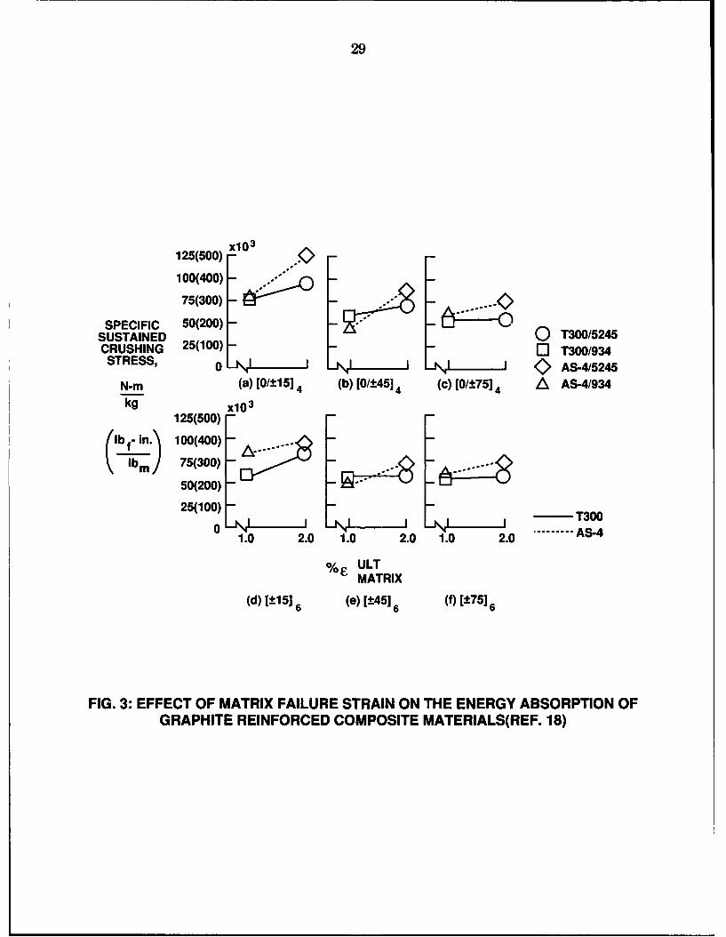
Farley [18] conducted further static crushing tests on cylinders to evaluate theinfluence of fiber and matrix maximum strain at failure on the energy absorption capabilityof graphite reinforced composite material systems. Composite material systems investigatedwere:
(1) Thornel 300/Fiberite 934 -- A low strain fiber in a low strain matrix.(2) Thornel 300/Narmco 5245C -- A low strain fiber in a high strain matrix.(3) Hercules AS4/Fiberite 934 -- A high strain fiber in a low strain matrix.(4) Hercules AS4/Narmco 5245C -- A high strain fiber in a high strain matrix.
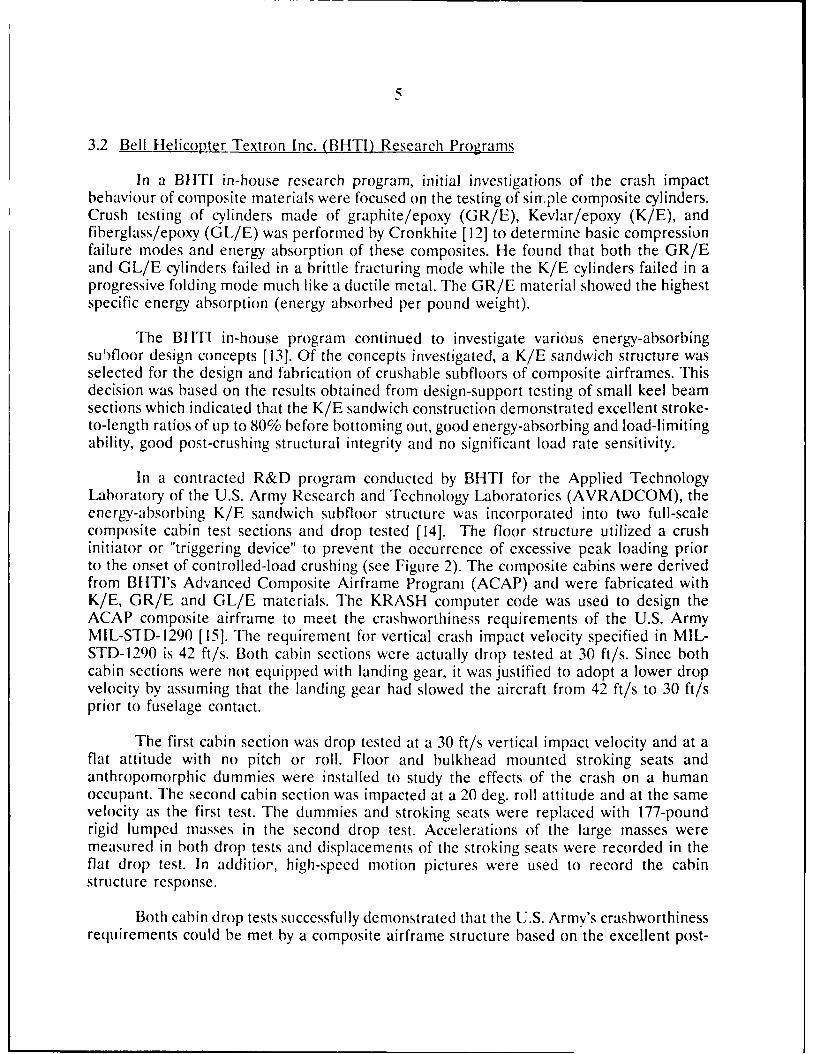
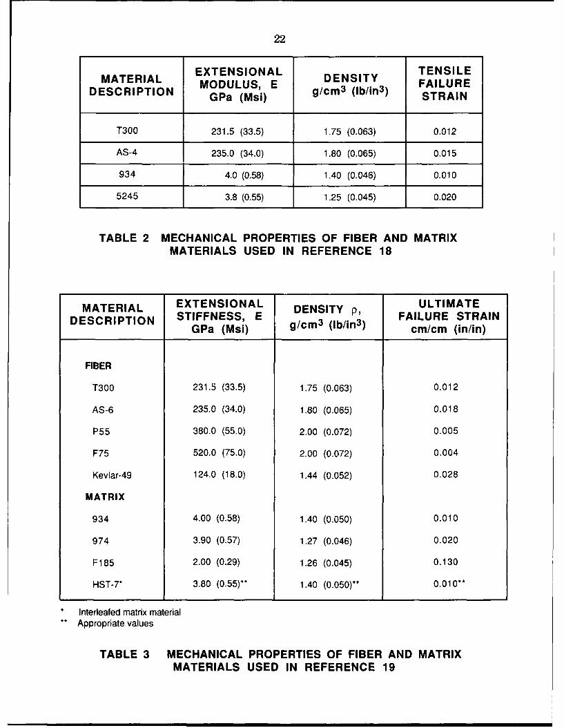
The material properties of the fiber and matrix materials used are presented inTable 2. The T300 and AS4 graphite fibers have similar extensional moduli although theAS4 fiber has approximately a 20% greater strain at failure than the T300 fiber. The 5245Cmatrix material has approximately a 100% greater strain at failure than the 934 matrixmaterial. Test results shown in Figure 3 indicated that the fiber and matrix maximum strainat failure significantly affected energy absorption. The higher strain-at-failure system,AS4/5245C, exhibited the highest energy absorption capability among the four compositesystems tested. All material systems tested exhibited typical failure modes of brittle fiberreinforced composite material systems. Two predominant failure modes were observed: thebending crushing mode and the fracturing crushing mode. The former mode is a lowerenergy-absorbing mode. For T300/5245C and AS4/5245C, the crushing mode of wasprimarily a fracturing crushing mode. The crushing characteristics demonstrated by thesefour material systems suggested that to achieve the maximum energy absorption from aparticular fiber, the matrix material must have a greater strain at failure than the fiber.
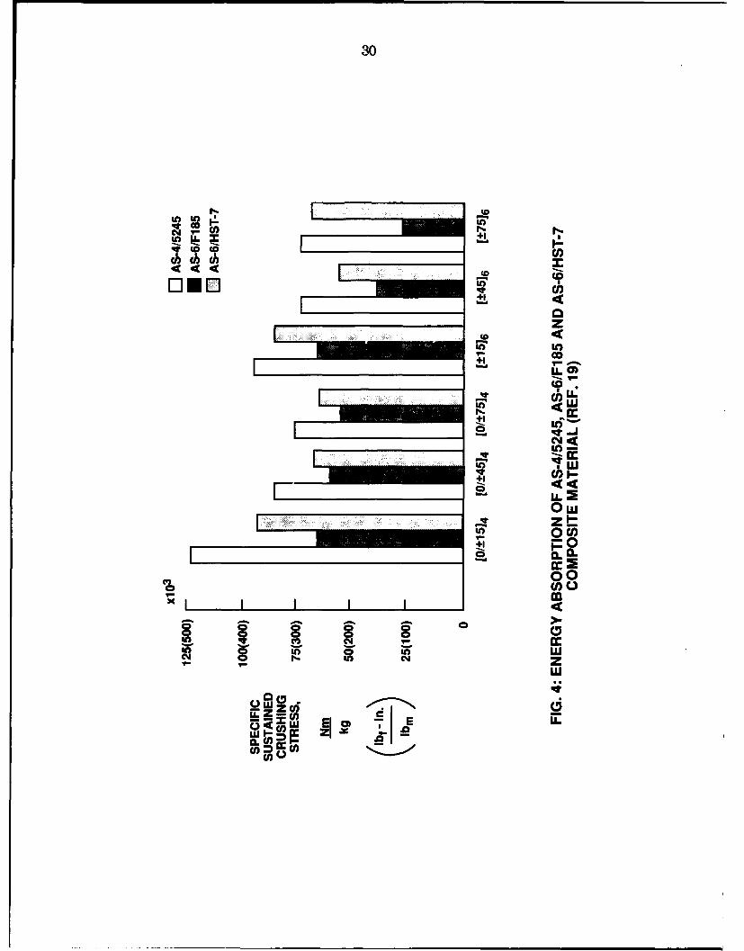
Farley's work described earlier did not investigate very high ultimate strain materialsystems. In an extensive collaborative effort with NASA, Farley, et al. [19] conducted staticcrushing tests on cylindrical specimens to evaluate the effects of very high ultimate failurestrain fibers (> .015 strain) and toughened matrices relative to energy absorption. Inaddition, the effects of fiber stiffness, fiber volume fraction, lamina stacking sequence, andhybrid material systems were assessed. The materials investigated and their mechanicalproperties are shown in Table 3.
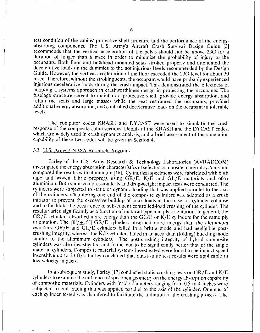
Static tests were conducted on cylinders fabricated from AS6/F185 and AS6/HST-7. The ultimate failure strain of the AS6 fiber is 17% higher than that of the AS4 fiber usedin Reference 18. The F185 matrix has approximately 600% greater failure strain than the5245C matrix used in Reference 18. The HST-7 matrix is an interleafed system where thebase matrix has similar properties as the 934 matrix while the interleafing material is a highstrain adhesive. Test results shown in Figure 4 indicate that the higher failure strainmaterial systems, AS6/F185 and AS6/HST-7, have lower energy absorption than the
8
AS4/5245C used in Reference 18. The cylinders fabricated from AS6/FI85 with plyorientations of [+45°] and [+75], were found to exhibit a ductile folding mode similar tothat of Kelvar reinforced composites and have post-crushing integrity. The folding modefor these two ply orientations was due to the suppression of the formation of interlaminarcracks in the high strain matrix. The AS6/HST-7 material exhibited better energyabsorption capability than the AS6/F185 material but it exhibited less energy absorptioncapability than the AS4/5245C material. The diameter of the AS6 fiber is smaller than thatof the AS4 fiber. This factor was considered to be the primary cause for the lowercompression strength of the two composite systems reinforced with the AS6 fibers whencompared with the AS4/5245C system.
The investigation of Farley, et al. [19] also found that energy absorption wasinversely proportional to fiber stiffness, the effect of fiber volume fraction on energyabsorption was less than 10% for both GR/E and K/E material systems, lamina stackingsequence could influence the energy absorption of the material tested by a factor of 3, andhybrid composite systems composed of graphite and Kevlar reinforcements resulted inbetter energy absorption capability than aluminium while retaining post-crushing integrity.
The work carried out by Farely, et al. on cylinders has established that compositematerial systems possess good energy absorption capability under compressive loadings.However, under tensile or bending conditions, structural integrity may be lost at initialfracture and energy absorption can be low. Under crash conditions, aircraft structuralelements experience complex loadings which are not always compressive. Therefore, a needexisted to examine generic composite structures under crash loadings.
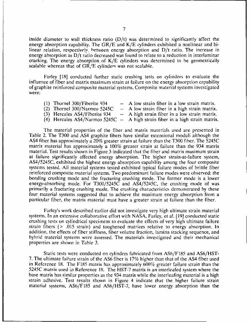
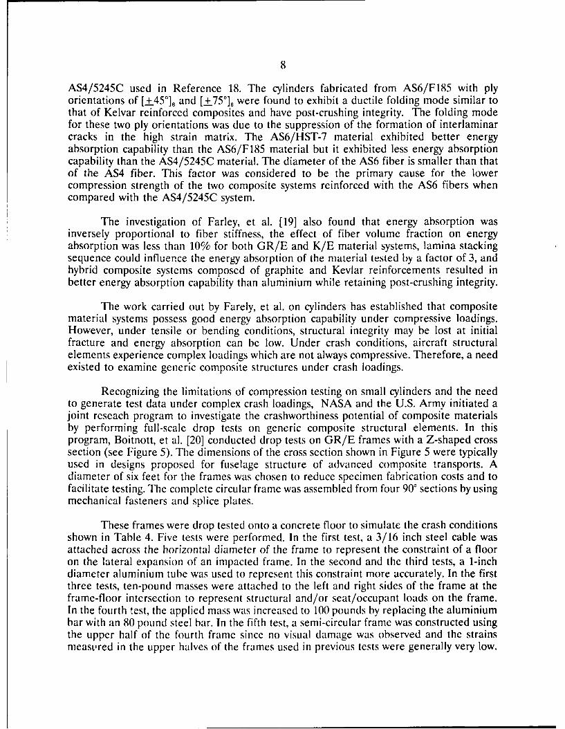
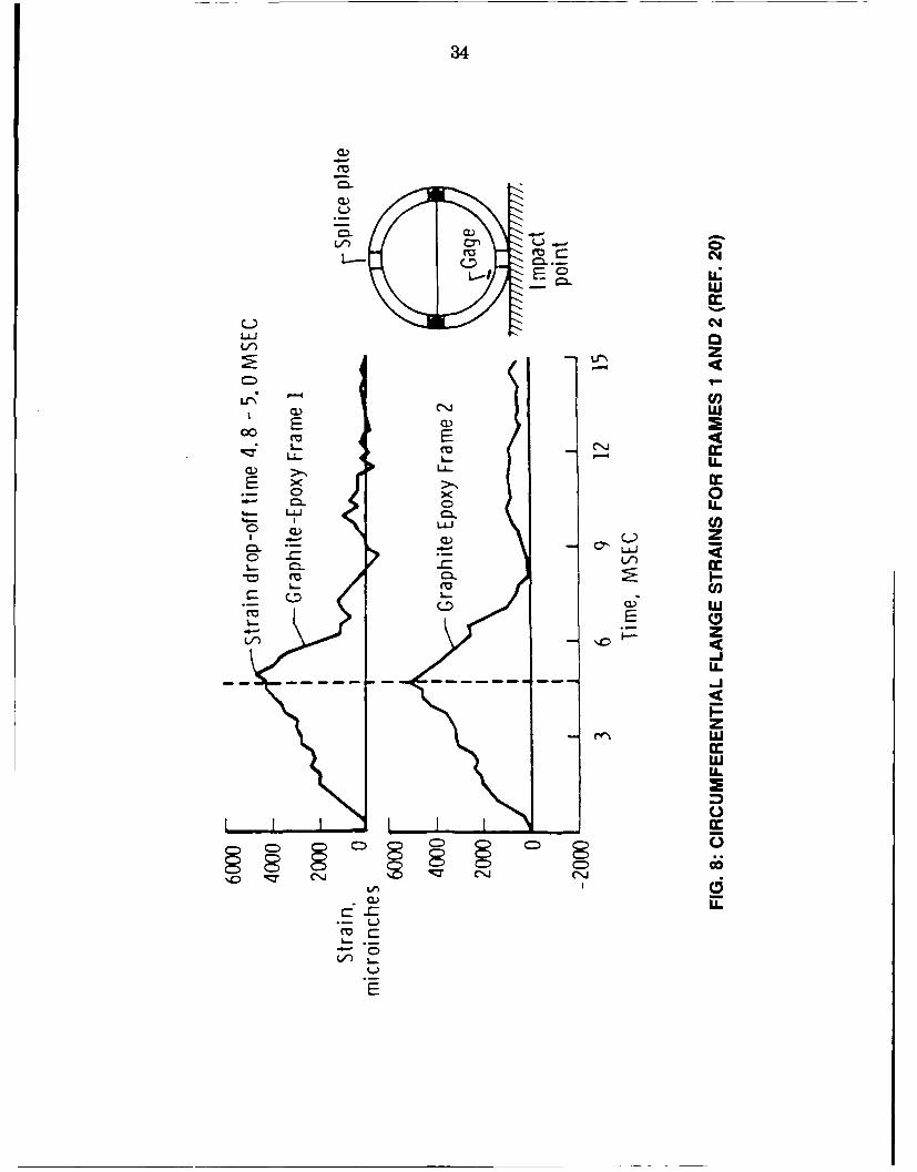
Recognizing the limitations of compression testing on small cylinders and the needto generate test data under complex crash loadings, NASA and the U.S. Army initiated ajoint reseach program to investigate the crashworthiness potential of composite materialsby performing full-scale drop tests on generic composite structural elements. In thisprogram, Boitnott, et al. [20] conducted drop tests on GR/E frames with a Z-shaped crosssection (see Figure 5). The dimensions of the cross section shown in Figure 5 were typicallyused in designs proposed for fuselage structure of advanced composite transports. Adiameter of six feet for the frames was chosen to reduce specimen fabrication costs and tofacilitate testing. The complete circular frame was assembled from four 90 sections by usingmechanical fasteners and splice plates.
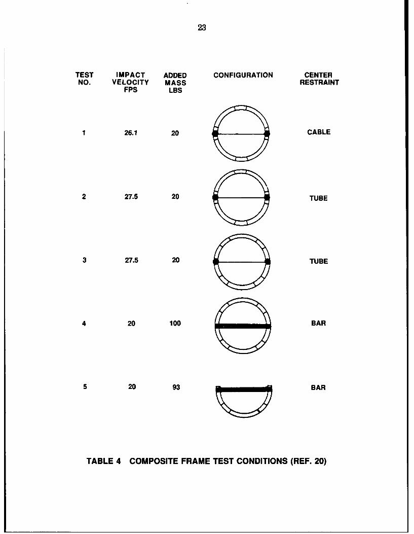
These frames were drop tested onto a concrete floor to simulate the crash conditionsshown in Table 4. Five tests were performed. In the first test, a 3/16 inch steel cable wasattached across the horizontal diameter of the frame to represent the constraint of a flooron the lateral expansion of an impacted frame. In the second and the third tests, a 1-inchdiameter aluminium tube was used to represent this constraint more accurately. In the firstthree tests, ten-pound masses were attached to the left and right sides of the frame at theframe-floor intersection to represent structural and/or seat/occupant loads on the frame.In the fourth test, the applied mass was increased to 100 pounds by replacing the aluminiumbar with an 80 pound steel bar. In the fifth test, a semi-circular frame was constructed usingthe upper half of the fourth frame since no visual damage was observed and the strainsmeasured in the upper halves of the frames used in previous tests were generally very low.
9
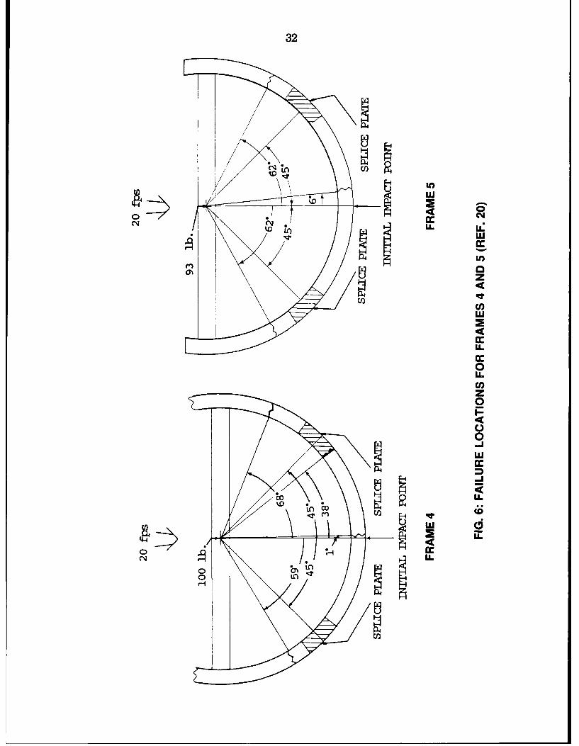
A steel bar similar to the one used in the fourth test but slightly longer was used tosimulate the floor constraint and to provide seat/occupant mass. In the first two tests, theframes were oriented so that impact occurred in the lower half of the frames at a spliceplate. In subsequent tests, the frames were rotated 450 so that impact occurred in the lowerhalf of the frames at a location midway between splice plates. Accelerometer, strain gauge,and high-speed photographic measurements were made and these data were used tocharacterize the impact behaviour of frames with different masses to represent structuralor seat/occupant masses.
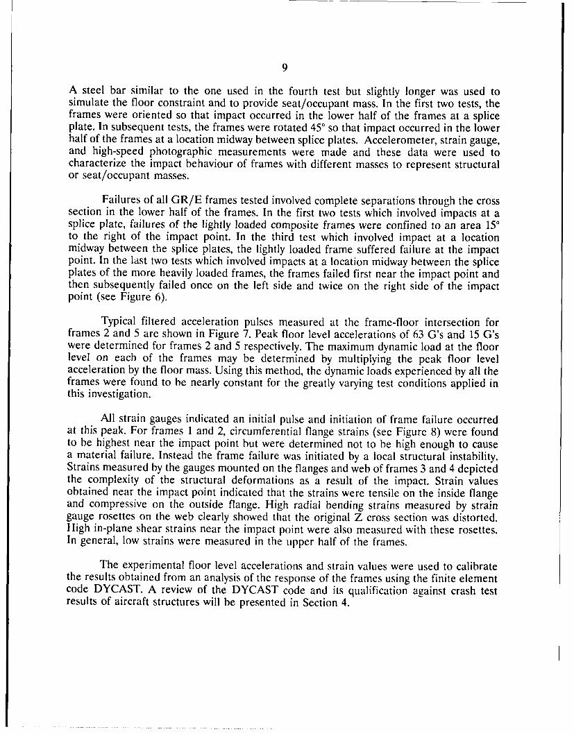
Failures of all GR/E frames tested involved complete separations through the crosssection in the lower half of the frames. In the first two tests which involved impacts at asplice plate, failures of the lightly loaded composite frames were confined to an area 150to the right of the impact point. In the third test which involved impact at a locationmidway between the splice plates, the lightly loaded frame suffered failure at the impactpoint. In the last two tests which involved impacts at a location midway between the spliceplates of the more heavily loaded frames, the frames failed first near the impact point andthen subsequently failed once on the left side and twice on the right side of the impactpoint (see Figure 6).
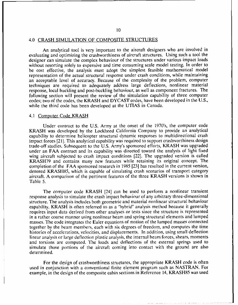
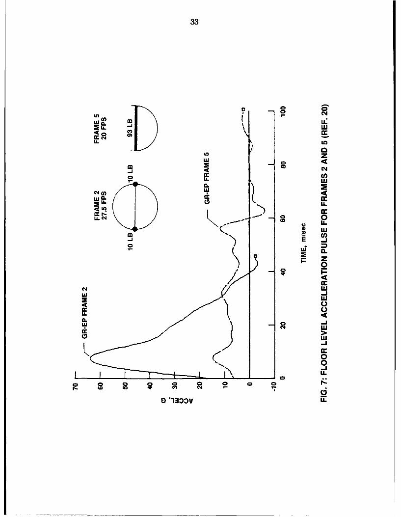
Typical filtered acceleration pulses measured at the frame-floor intersection forframes 2 and 5 are shown in Figure 7. Peak floor level accelerations of 63 G's and 15 G'swere determined for frames 2 and 5 respectively. The maximum dynamic load at the floorlevel on each of the frames may be determined by multiplying the peak floor levelacceleration by the floor mass. Using this method, the dynamic loads experienced by all theframes were found to be nearly constant for the greatly varying test conditions applied inthis investigation.
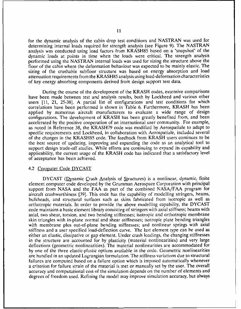
All strain gauges indicated an initial pulse and initiation of frame failure occurredat this peak. For frames 1 and 2, circumferential flange strains (see Figure 8) were foundto be highest near the impact point but were determined not to be high enough to causea material failure. Instead the frame failure was initiated by a local structural instability.Strains measured by the gauges mounted on the flanges and web of frames 3 and 4 depictedthe complexity of the structural deformations as a result of the impact. Strain valuesobtained near the impact point indicated that the strains were tensile on the inside flangeand compressive on the outside flange. High radial bending strains measured by straingauge rosettes on the web clearly showed that the original Z cross section was distorted.High in-plane shear strains near the impact point were also measured with these rosettes.In general, low strains were measured in the upper half of the frames.
The experimental floor level accelerations and strain values were used to calibratethe results obtained from an analysis of the response of the frames using the finite elementcode DYCAST. A review of the DYCAST code and its qualification against crash testresults of aircraft structures will be presented in Section 4.
10
4.0 CRASH SIMULATION OF COMPOSITE STRUCTURES
An analytical tool is very important to the aircraft designers who are involved inevaluating and optimizing the crashworthiness of aircraft structures. Using such a tool thedesigner can simulate the complex behaviour of the structures under various impact loadswithout resorting solely to expensive and time consuming scale model testing. In order tobe cost effective, the analysis must adopt the simplest feasible mathematical modelrepresentation of the actual structural response under crash conditions, while maintainingan acceptable level of accuracy. Because of the complexity of the problem, computertechniques are required to adequately address large deflections, nonlinear materialresponse, local buckling and post-buckling behaviour, as well as component fractures. Thefollowing section will present the review of the simulation capability of three computercodes; two of the codes, the KRASH and DYCAST codes, have been developed in the U.S.,while the third code has been developed at the UTIAS in Canada.
4.1 Computer Code KRASH
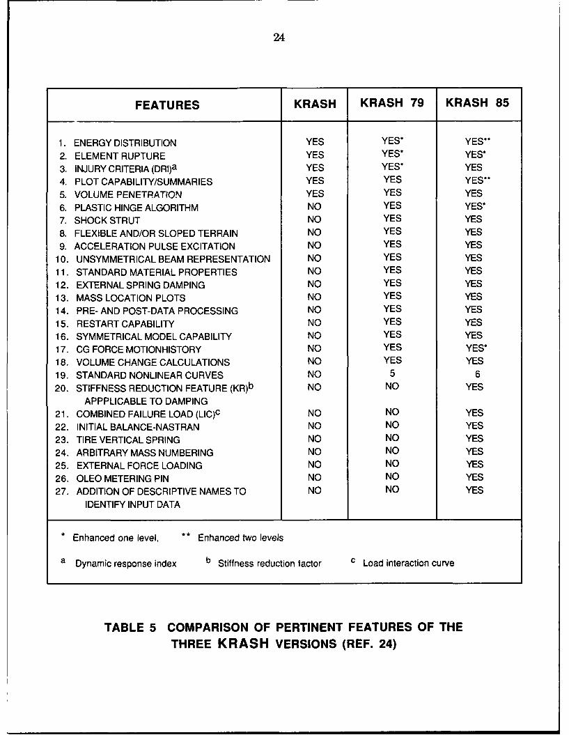
Under contract to the U.S. Army at the onset of the 1970's, the computer codeKRASH was developed by the Lockheed California Company to provide an analyticalcapability to determine helicopter structural dynamic responses to multidirectional crashimpact forces [21]. This analytical capability was required to support crashworthiness designtrade-off studies. Subsequent to the U.S. Army's sponsored efforts, KRASH was upgradedunder an FAA contract and its capability was directed toward the analysis of light fixedwing aircraft subjected to crash impact conditions [22]. The upgraded version is calledKRASH79 and contains many new features while retaining its original concept. Thecompletion of the FAA sponsored research in 1985 [23] has resulted in the current version,denoted KRASH85, which is capable of simulating crash scenarios of transport categoryaircraft. A comparison of the pertinent features of the three KRASH versions is shown inTable 5.
The computer code KRASH [24] can be used to perform a nonlinear transientresponse analysis to simulate the crash impact behaviour of any arbitrary three-dimensionalstructure. The analysis includes both geometric and material nonlinear structural behaviourcapability. KRASH is often referred to as a "hybrid" analysis method because it generallyrequires input data derived from other analyses or tests since the structure is representedin a rather coarse manner using nonlinear beam and spring structural elements and lumpedmasses. The code integrates the Euler equations of motion of the lumped masses connectedtogether by the beam members, each with six degrees of freedom, and computes the timehistories of accelerations, velocities, and displacements. In addition, using small deflectionlinear analysis or large deflection plastic analysis, the internal beam forces, shears, momentsand torsions are computed. The loads and deflections of the external springs used tosimulate those portions of the aircraft coming into contact with the ground are alsodetermined.
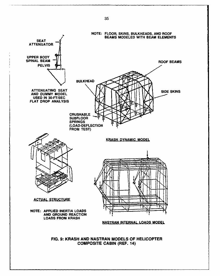
For the design of crashworthiness structures, the appropriate KRASH code is oftenused in conjunction with a conventional finite element program such as NASTRAN. Forexample, in the design of the composite cabin sections in Reference 14, KRASH85 was used
11
for the dynamic analysis of the cabin drop test conditions and NASTRAN was used fordetermining internal loads required for strength analysis (see Figure 9). The NASTRANanalysis was conducted using load factors from KRASH85 based on a "snapshot" of thedynamic loads at points in time when the loads were critical. The strength analysisperformed using the NASTRAN internal loads was used for sizing the structure above thefloor of the cabin where the deformation behaviour was expected to be mainly elastic. Thesizing of the crushable subfloor structure was based on energy absorption and loadattenuation requirements from the KRASH85 analysis using load-deformation characteristicsof key energy absorbing components derived from design support test data.
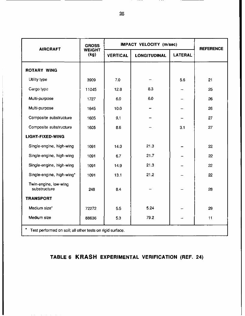
During the course of the development of the KRASH codes, extensive comparisonshave been made between test and analysis results, both by Lockheed and various otherusers [11, 21, 25-38]. A partial list of configurations and test conditions for whichcorrelations have been performed is shown in Table 6. Furthermore, KRASH has beenapplied by numerous aircraft manufacturers to evaluate a wide range of designconfigurations. The development of KRASH has been greatly benefited from, and beenaccelerated by the positive cooperation of an international user community. For example,as noted in Reference 38, the KRASH79 code was modified by Aerospatiale to adapt tospecific requirements and Lockheed, in collaboration with Aerospatiale, included severalof the changes in the KRASH85 code. The feedback from KRASH users continues to bethe best source of updating, improving and expanding the code as an analytical tool tosupport design trade-off studies. While efforts are continuing to expand its capability andapplicability, the current usage of the KRASH code has indicated that a satisfactory levelof acceptance has been achieved.
4.2 Computer Code DYCAST
DYCAST (Dynamic Crash Analysis of Structures) is a nonlinear, dynamic, finiteelement computer code developed by the Grumman Aerospace Corporation with principalsupport from NASA and the FAA as part of the combined NASA/FAA program foraircraft crashworthiness [39]. This code has the capability of modelling stringers, beams,bulkheads, and structural surfaces such as skins fabricated from isotropic as well asorthotropic materials. In order to provide the above modelling capability, the DYCASTcode maintains a basic element library consisting of stringers with axial stiffness; beams withaxial, two shear, torsion, and two bending stiffnesses; isotropic and orthotropic membraneskin triangles with in-plane normal and shear stiffnesses; isotropic plate bending triangleswith membrane plus out-of-plane bending stiffnesses; and nonlinear springs with axialstiffness and a user specified load-deflection curve. The last element type can be used aseither an elastic, dissipative or gap element. Under crash loadings, the changing stiffnessesin the structure are accounted for by plasticity (material nonlinearities) and very largedeflections (geometric nonlinearities). The material nonlinearities are accommodated forby one of the three elastic-plastic options available in the code. Geometric nonlinearitiesare handled in an updated Lagrangian formulation. The stiffness variations due to structuralfailures are computed based on a failure option which is imposed automatically whenevera criterion for failure strain of the material is met or manually set by the user. The overallaccuracy and computational cost of the simulation depends on the number of elements anddegrees of freedom used. Refining the model may improve simulation accuracy, but always
12
drives up the costs. Therefore, the analyst must have sufficient expertise in modelling thestructure for the nonlinear crash analysis in order to produce sufficiently accurate resultswithin acceptable time and cost restraints.
The total cost of an analysis is composed of the labour involved in creating themodel and evaluating the results and the cost of using the computer. Based on theexperience of Winter, et al. [40], a first time full vehicle finite element model could requireup to four person-months of effort to prepare and verify, depending on the model size andcomplexity. However, after the first time model is complete, it can be modified easily andat small cost, enabling the investigation of the effects of structural modifications. Thecomputational costs are also dependent on model size and complexity. For a linear stressand vibration analysis, a finite element model could contain more than 20,000 degrees offreedom. Such a model would probably have already existed for the conventional design andanalysis of the structure. However, the use of such an existing model, instead of creatinga new one especially prepared for crash analysis, could save much time and labour in modelpreparation, but because of the limitations of current computers, a nonlinear dynamicanalysis of this type of model using the DYCAST code is currently not feasible because ofthe computer time required. The optimal model size for a nonlinear finite element problemis therefore greatly dependent on the speed and memory capacity of the computer. Againbased on the experience of Winter, et al. [40], a model having between 2000 and 3000degrees of freedom and requiring several thousand time steps could complete the analysisovernight on the vector computers, such as the Cray-1 and the Cyber 205, using an in-coresolution with a memory of 2 million words. Larger problems or smaller computer memorycapacity and speed will require restart runs and longer time to complete the analysis. It isobvious that the finite element model must be designed to fit the available computerresources and includes all the important details for an accurate crash simulation.
In order to model the structure within available computer resources and produceaccurate results, the DYCAST code allows the use of simple nonlinear spring elements tomodel crushable, energy absorbing components which exhibit extremely nonlinearbehaviour. The advantage is that instead of requiring a large number of plate elementsinvolving several thousand degrees of freedom for each collapse zone, only one degree offreedom is added for each nonlinear spring. However, this hybrid method requires theanalyst to specify the expected large deformation behaviour by providing an input curve ofload vs deflection or moment vs rotation generated by conducting component testing.
Applications of the DYCAST code include crash simulations of an aircraft fuselagesubfloor [41], composite helicopter cabin sections [14], composite fuselage frames [20], anaircraft seat [42], and transport fuselage sections of the joint FAA/NASA Controlled ImpactDemonstration test [30]. Of relevant interest to the present review is the accuracy of thecrash simulation of composite structures using the DYCAST code. As mentioned earlier,the DYCAST analytical results were compared with the test results of the crash testing ofthe composite fuselage frames in the joint U.S. Army/NASA program 1201. As noted inReference 20, only fair correlation was obtained between predicted and experimental frame-floor level accelerations. Frame response predicted by the DYCAST analysis showedsignificant sensitivity to moderate changes in the failure strain. Additional analytical studiesare required to assess further the capabilities and possible improvements needed to analyze
13
composite structural elements using the DYCAST computer code.
As mentioned earlier, both the KRASH and DYCAST computer codes wereevaluated in the BHTI research program on composite helicopter fuselage technology [141.These two codes were used to simulate the crash responses of the full-scale compositecabins under flat drop test and 20' roll drop test conditions. The analysis results obtainedfrom these codes were correlated with the drop test results. In addition, the KRASH codewas used to design the composite cabins for the drop tests in accordance with thecrashworthiness requirements of the MIL-STD-1290. Based on the good crash impactperformance of the composite cabins and satisfactory correlations of analytical and testresults, KRASH proved to be a useful and reasonably accurate analysis tool for thecrashworthiness design of composite structures. The accuracy of the DYCAST predictionsof damage, deformation, and accelerations was generally good for the flat drop test.However, the agreement between DYCAST and test results for the 20 roll drop test wasmixed, with fairly good agreement in deformation and generally poor agreement inacceleration predictions.
4.3 Crash Dynamics Computer Code Developed at UTIAS
Under the joint sponsorship of the TDC and the Natural Sciences and EngineeringResearch Council of Canada, a comprehensive program was undertaken at the Universityof Toronto Institute of Aerospace Studies (UTIAS) to investigate, both analytically andexperimentally, the dynamic behaviour of aircraft fuselage structures subjected to variousimpact conditions [43]. Two analytical models were developed to derive the motionequations, one based on a self-consistent finite element (CFE) technique [44] and the otheron a more approximate, lumped mass finite element approach (LMFE) [45]. Extensivevertical drop and free-flight impact tests of scale model fuselage sections of stiffenedaluminium were conducted using a pendulum gantry developed at UTIAS for a wide rangeof wing loads, angles of incidence and impact velocities [44]. Test data were obtained interms of structural strains, G loads and high speed photography of the modes of dynamiccollapse. Analytical results obtained by using the CFE and LMFE techniques demonstratedgood correlations with experimentally generated G loads, dynamic peak strains and transientfailure modes.
In a subsequent phase of the UTIAS program, partly funded by the CanadianDefence Research Establishment Suffield and the Natural Sciences and EngineeringResearch Council of Canada, a finite element computer model for analysing the crashresponse of stiffened composite fuselage structures was developed [46]. As demonstratedin Reference 46, the finite element computer model established by using a formulationbased on Reissner/Mindlin plate theories can treat stiffened laminated shell buckling, largedeflections, nonlinear material behaviour and element failure. Although experimentalcomparisons were not yet available, numerical results presented [46] for several test casesclearly showed that this code could determine transient displacements, velocities andaccelerations. As reported in Reference 47, a composite fuselage model one meter indiameter by two meters in length was constructed and flight impact tests were to beconducted following a numerical analysis of the model for given load conditions. It was alsostated that a non-destructive program was necessary to precede the final crash test to
14
optimize the amount of test data that could be obtained from such an expensive test article.However, a recent report indicated that flight impact tests of the composite fuselage hadnot been conducted [46]. Reference 46 was the most recent report which describes the flightimpact test status of the composite fuselage at UTIAS.
5.0 CONCLUSIONS AND RECOMMENDATIONS
A review of major research activities in North America related to crashworthinessof composite structures was conducted. The intent of the review was to identify potentialCanadian contributions to research on the crashworthiness of small aircraft containingcomposite structures and to propose research to complement the on-going activities in theU.S. This review effort encompassed the work undertaken or sponsored by the FAA, theU.S. Army, NASA, Bell Helicopter Textron Inc., Lockheed California Company andGrumman Aerospace Corporation in the U.S. and Transport Canada/Sypher:MuellerInternational Inc. and the University of Toronto Institute of Aerospace Studies in Canada.
The conclusions of this review have led to specific recommendations for furtheractivities which will provide long and short term benefits in improving the crashworthinessof small aircraft containing composite structure. These proposed activities are concentratedon the dynamic impact testing of composite structures and on computational structuraltechniques where expertise already exists in Canada. Consequently, it is believed that theseresearch activities have the potential to achieve their objectives. In order to maximize thechance of achieving the research objectives, these activities should be conducted in acoodinated manner involving several centers of expertise across Canada since the resourcesof most Canadian organizations are very stretched and too limited to make any effectivecontribution alone. The conclusions and the corresponding recommendations are providedas follows:
1. The research activities in crashworthiness design of composite structures pursuedin the U.S. were highly focused on rotary wing and transport type aircraft. Theseresearch activities have generated a data base which will have applicability towardsthe establishment of crashworthiness design guidelines for small aircraft containingcomposite and/or composite/metal hybrid structures. However, it is consideredextremely difficult if not impossible to directly relate crashworthiness design criteriaand regulatory requirements developed from research on these types of aircraft tosmall aircraft containing composite and/or composite/metal hybrid structuresbecause of size effects. Research on composite cylinders indicated that GR/Ematerial sytems were not geometrically scalable. This review has shown thatinsufficient research is being directed, both in the U.S. and Canada, into the impactdynamics of small aircraft containing composite and/or composite/metal hybridstructures. Therefore, size effects on the crashworthiness behaviour of compositestructures should be addressed before the application of the current crashworthinessdesign guidelines to composite small aircraft. Before the concern on size effects isresolved, full-scale crash testing of representative composite structures should beconducted.
15
2. This review indicated that a parametric study of the effects of the design variablesaffecting composite joints on failure mode, strength and energy absorption underdynamic loading had not been undertaken. Since a parametric study can provideuseful insight and data for the optimization of composite joint design with respectto crashworthiness, it is highly recommended as an immediate research item.
3. This review has shown that the approach of using appropriate testing in conjunctionwith supportive analyses to assess design concepts of crash dynamics is feasible andcould become a practical design methodology for composite small aircraft. The firstrecommendation will generate a data base to calibrate the analysis methods. State-of-the-art crash dynamics analysis codes reviewed include the KRASH, DYCASTand the code developed at the UTIAS. All three codes are capable of simulatingcrash behaviour of both metal and composite structures and have proved to bevaluable analytical tools for crashworthiness design trade-off studies. The KRASHcode is the most widely used code and has an international user base. Any R&Dprogram would require the KRASH code to be commissioned in Canada becausethis will establish commonality in analytical tools with the U.S. as well as Europeanusers. Subsequent to the implementation of the KRASH code, an effort must bemade to gain experience in using the tool for the crashworthiness design of smallaircraft containing composite and/or composite/metal hybrid structures and todevelop a suitable material data base which is of interest to the Canadian aviationcommunity. This effort is necessary because the KRASH model is rather coarse andrequires test data and considerable experience to simulate crash scenarios.
4. Since the KRASH code cannot provide the internal load distribution of a structure,a complementary structural analysis tool is required for strength prediction. Both theU [IAS and DYCAST finite element simulations allow a more detailed and completerepresentation of the structure but require considerable modelling setup time andcomputer run time. Further work is recommended to explore the possibility to usethe two simulations to complement each other, that is, the KRASH code could beused for overall vehicle response and the UTIAS or DYCAST for modelling criticalareas of the structure where a more detailed structural representation and analysisis required. This could lead to a more cost-effective analysis.
5. The capability of the UTIAS code to simulate the crash behaviour of compositestructures has not been subjected to experimental verification. A comparison betweenthe UTIAS code and other codes has not been conducted. In order to use theUTIAS code or to use the UTIAS code with KRASH for the design of crashworthycomposite aircraft structures, the capability of the UTIAS code must be verifiedagainst experimental results. Also, it is considered worthwhile to compare the UTIAScode with DYCAST and KRASH.
6. This review clearly shows that the crashworthiness behaviour of an aircraft dependson the materials used, as well as the construction and the shape of the structuralelements. Preferred materials in crash application must exhibit non-brittle behaviourso that energy is absorbed through plastic deformation and maintain post-crashstructural integrity. Conventional GR/E and GL/E material systems were shown to
16
be brittle under crush loading. However, K/E as well as composite systems with highstrain-to-failure graphite fiber and toughened thermoset matrices were found toexhibit ductile folding mode similar to aluminium and to possess post-crushingintegrity. The energy absorption and failure mode were found to be affected byhybrid construction, lamina stacking sequence, lay-up, fiber stiffness, matrix strain atfailure and fiber volume fraction. A crush initiator or "triggering device" resultingfrom chamfering the end of composite cylinders or corrugated web design withnotched attached angles in crushable subfloor construction was found to be effectivein preventing excessive buildup of peak loads before the onset of controlled-loadcrushing. Since small aircraft containing composite and/or composite/hybridstructures may exhibit different dynamic responses under crash conditions whencompare with helicopters and transport type aircraft, it is important to catalogue thedetail design features for small composite/hybrid aircraft and to investigate theirenergy absorption capabilities. This recommendation will lead to the establishmentof design data bases for input to analytical models.
7. The U.S. Army MIL-STD-1290A should be used as a basis for the development ofcrashworthiness design guidelines for small aircraft containing composite structures.The data to be generated from the recommended research items described in thissection would be useful for the modification of the design criteria contained in MIL-STD-1290A to suit the requirements for composite aircraft structures.
6.0 ACKNOWLEDGEMENT
This work was carried out under the sponsorship of NAE Structures and MaterialsProject 07336, Fatigue and Damage Tolerance of Structures.
7.0 REFERENCES
1. Monroe, R. L. and McLeish, W., "Small Aircraft Crashworthiness," TechnicalDevelopment Center Report TP8655E, July 1987.
2. Monroe, R. L. and McLeish, W., "Crashworthiness R&D Plan", Sypher:MuellerInternational Inc., to be published as a Transport Development Center Report.
3. Desjardins, S.P., Lannanen, D.H. and Singley, D.T., III, "Aircraft Crash SurvivalDesign Guide," USARTL-TR-79-22A to -22E, Vol. I to V, 1980.
4. Military Standard, MIL-STD-1920A(AV), "Light Fixed- and Rotary-Wing AircraftCrash Resistance," Department of Defense, Washington, D. C., 26 September 1988.
5. Poon, C., "Literature Review on the Design of Composite Mechanically FastenedJoints," NAE-AN-37, National Research Council Canada, Ottawa, February 1986.
17
6. Poon, C. and Farahbakhsh, B., "Impact Testing of Adhesively-Bonded AluminiumJoints," NAE-LTR-ST-1670, National Research Council Canada, Ottawa, June 1988.
7. Wittlin, G. and Caiafa, C., "Transport Airplane Crash Simulation, Validation andApplication to Crash Design Criteria," Proceedings of the AGARD Conference onEnergy Absorption of Aircraft Structures as an Aspect of Crashworthiness,Luxembourg, AGARD-CP-443, May 1988.
8. Jackson, A. C., "Transport Composite Fuselage Transmission," NASA CR 4035,December 1986.
9. "DC-10 Fuselage Drop Test Report," Report No. 7252-1, Arvin/Calspan Reportprepared for the FAA Technical Center, Atlantic City, N.J., March 1984.
10. Johnson, D. and Garodz, L., "Crashworthiness Experiment Summary, Full-ScaleTransport Controlled Impact Program," DOT/FAA/CT-85/20, June 1986.
11. Wittlin, G., "KRASH Analysis Correlation -- Transport Airplane Controlled ImpactDemonstration Test," DOT/FAA/CT-86/13, December 1986.
12. Cronkhite, J. D. and Berry, V. L., "Crashworthy Airframe Design Concepts --Fabrication and Testing," NASA CR3603, Washington, D.C., September 1982.
13. Cronkhite, J. D., Berry, V. L., and Winter, R., "Investigation of the Crash ImpactCharacteristics of Htelicopter Composite Structures," USAAVRADCOM TR-82-D-14, Applied Technology Laboratory, U.S. Army Research and TechnologyLaboratories, Fort Eustis, Virginia, February 1983.
14. Cronkhite, J. D., "Design of Airframe Structures for Crash Impact," Proceedings ofthe American Helicopter Society Specialists' Meeting on Crashworthy Design ofRotorcraft, Atlanta, Georgia, April 1986.
15. Carnell, B. L. and Pramanik, M., "ACAP Crashworthiness Analysis by KRASH,"American Helicopter Society Journal, Vol. 29, 1984, pp. 38-42.
16. Farley, G. L., "Energy Absorption of Composite Materials," Journal of CompositeMaterials, Vol. 17, May 1983, pp. 267-279.
17. Farley, G. L., "Effect of Specimen Geometry on the Energy Absorption Capabilityof Composite Materials," Journal of Composite Materials, Vol. 20, July 1986, pp.390-400.
18. Farley, G. L., "Effect of Fiber and Matrix Maximum Strain on the Energy Absorptionof Composite Materials," Journal of Composite Materials, Vol. 20, July 1986, pp. 322-334.
18
19. Farley, G. L., Bird, R. K. and Modlin, J. T., "The Role of Fiber and Matrix in CrashEnergy Absorption of Composite Materials," Proceedings of the American HelicopterSociety Specialists' Meeting on Crashworthy Design of Rotorcraft, Atlanta, Georgia,April 7-9, 1986.
20. Boitnott, R. L., Fasanella, E. L., Calton, L. E. and Carden, H. D., "Impact Responseof Composite Fuselage Frames," SAE Technical Paper No. 871009, presented at theGeneral Aviation Aircraft Meeting and Exposition, Wichita, Kansas, April 28-30,1987.
21. Wittlin, G. and Gamon, M. A., "Experimental Program for the Development ofImproved Helicopter Structural Crashworthiness Analytical and Design Techniques,"Lockheed-California Company, USAAMRLDL-TR-72-72, Volumes I and II, May1973.
22. Wittlin, G. and Gamon, M. A., "Full-Scale Crash Test Experimental Verification ofa Method of Analysis for General Aviation Airplane Structural Crashworthiness,"Lockheed-California Company, FAA Report FAA-RD-77-188, February 1978.
23. Gamon, M. A., Wittlin, G. and LaBarge, W. L., "KRASH85 User's Guide --
Input/Output Format," Lockheed-California Company, DOT/FAA/CT-85/10, May1985.
24. Wittlin, G.,"Program KRASH: Evolution of an Analy, -al Tool to Evaluate AircraftStructural Crash Dynamics Response," Proceedings of the American HelicopterSociety Specialists' Meeting on Crashworthy Design of Rotorcraft, Atlanta, Georgia,April 1986.
25. Badrinath, Y. V., "Simulation Correlation and Analysis of Structural Response of aCH-47-A to Crash Impact," USARTL-TR-78-24, August 1978.
26. Mens, J., "Suirvey of Crashworthiness Achievements on Aerospatiale Helicopters,"41st Annual Forum, American Helicopter Society, Fort Worth, texas, May 1985.
27. Cronkhite, J. D. and Berry, V. L., "Investigation of the Crash Impact Characteristicsof Helicopter Composite Structures," USAAVRADCOM-TR-82-D-14, February1983.
28. Hayduk, R. J., Thomson, R. G., Wittlin, G. and Kamat, M. P., "Nonlinear StructuralCrash Dynamics Analysis," SAE Paper 790588, April 1979.
29. Wittlin, G. and Lackey, D., "Analytical Modelling of Transport Aircraft CrashScenarios to Obtain Floor Pulses," FAA Report DOT/FAA/CT-83/23, NASA CR1666089, April 1983.
19
30. Wittlin, G. and Caiafa, C., "Transport Airplane Crash Simulation, Validation andApplication to Crash Design Criteria," Proceedings of the AGARD Conference onEnergy Absorption of Aircraft Structures as an Aspect of Crashworthiness,Luxembourg, AGARD-CP-443, May 1988.
31. Och, F., "Crashworthiness Activities on MBB Helicopters," Proceedings of theAGARD Conference on Energy Absorption of Aircraft Structures as an Aspect ofCrashworthiness, Luxembourg, AGARD-CP-443, May 1988.
32. Nitschke, D. and Frese, J., "Crushing Behaviour of Helicopter Subfloor Structures,"Proceedings of the AGARD Conference on Energy Absorption of Aircraft Structuresas an Aspect of Crashworthiness, Luxembourg, AGARD-CP-443, May 1988.
33. Jarzab, W. and Schwarz, R., "Crashworthiness of Aircraft Structures," Proceedingsof the AGARD Conference on Energy Absorption of Aircraft Structures as anAspect of Crashwortxiness, Luxembourg, AGARD-CP-443, May 1988.
34. Mens, J. and Bianchini, J. C., "Computing Codes for Development of HelicopterCrashworthy Structures and Test Substantiation," Proceedings of the AmericanHelicopter Society Specialists' Meeting on Crashworthy Design of Rotorcraft,Atlanta, Georgia, April 1986.
35. Pramanik, M. B. and Carnell, B. L., "Landing Gear Performance Simulation byKRASH Program," Proceedings of the American Helicopter Society Specialists'Meeting on Crashworthy Design of Rotorcraft, Atlanta, Georgia, April 1986.
36. Wittlin, G., "Aircraft Crash Dynamics: Modelling, Verification and Application," inStructural Crashworthiness, Edited by Jones, N. and Wierzbicki. T., Butterworth andCo., London and Boston, 1983, pp. 259-282.
37. Lamborn, L. C., "Crew Seat Stroke Requirements for Helicopter Rolled AttitudeImpact Crashworthiness," Proceedings of the American Helicopter Society Specialists'Meeting on Crashworthy Design of Rotorcraft, Atlanta, Georgia, April 1986.
38. Soltis, S., Caiafa, C., Wittlin, G., "FAA Structural Crash Dynamics Program Update -- Transport Category Aircraft," SAE Paper 851887, Long Beach, CA., October 1985.
39. Pifko, A. B., Winter, R. and Ogilvie, P. L., "DYCAST -- A Finite Element Programfor the Crash Analysis of Structures," NASA CR 4040, Washington, D.C., January1987.
40. Winter, R. and Pifko, A. B., "Modelling Strategies for Finite Element CrashSimulation of Complete Vehicles," Proceedings of the American Helicopter SocietySpecialists' Meeting on Crashworthy Design of Rotorcraft, Atlanta, Georgia, April1986.
20
41. Carden, H. D. and t-ayduk, R. J., "Aircraft Subfloor Response to Crash Loadings,"SAE Paper 810614, 1981.
42. Alfaro-Bou, E., Williams, M. S. and Fasanella, E. L., "Determination of Crash TestPulses and their Application to Aircraft Seat Analysis," SAE Paper 810611, 1981.
43. Tennyson, R. C., Nanyaro, A. P., Teichman, H. C. and Hansen, J. S.,"Crashworthiness of Light Aircraft Structures," Transport Canada Research andDevelopment Centre Report TP3927, 1981.
44. Tennyson, R. C. and Hansen, J. S., "Study of the Crash Behaviour of AircraftFuselage Structures," in Structural Crashworthiness, Edited by Jones, N., andWierzbicki, T., Butterworth and Co., London and Boston, 1983, pp. 218-258.
45. Tennyson, R. C., Teichman, H., Nanyaro, A. P. and Mabson, G., "Study of theCrashworthiness of Light Aircraft Structures," Proceedings of the Twenty SecondStructures, Structural Dynamics and Materials Conference,AIAA/ASME/ASCE/AHS, Atlanta, Georgia, 1981.
46. Hansen, J. S. and Tennyson, R. C., "The Dynamic Behaviour of Stiffened CompositeFuselage Shell Structures," Proceedings of the AGARD Conference on EnergyAbsorption of Aircraft Structures as an Aspect of Crashworthiness, Luxembourg,AGARD-CP-443, May 1988.
47. Johnston, J., "Design and Fabrication of a Scaled Composite Fuselage Section,"University of Toronto, M.A.Sc. Thesis, 1984.
21
LUa,z
o C> Nj U) 0 N r-0N m N cn) o N -
0<-J (>u z
0
z0
0 a) )
I-i < ~ -1 . 5 Mu z00 0 -0%-C j
-0 0
Ew a..
C~ M)ou-~~ 0 0 UC .
C CcCUL0 0 - -
~ 50 0 :5) C CC
ot 0 0 ) Cc
M- -0 - - - - CDW ~C
00 c 00)
a) 0LLa 0 c
22
EXTENSIONAL TENSILEMATERIAL MODULUS, E DENSITY FAILURE
DESCRIPTION GPa (Msi) g/cm 3 (lb/in 3) STRAIN
T300 231.5 (33.5) 1.75 (0.063) 0.012
AS-4 235.0 (34.0) 1.80 (0.065) 0.015
934 4.0 (0.58) 1.40 (0.046) 0.010
5245 3.8 (0.55) 1.25 (0.045) 0.020
TABLE 2 MECHANICAL PROPERTIES OF FIBER AND MATRIXMATERIALS USED IN REFERENCE 18
MATERIAL EXTENSIONAL DENSITY p, ULTIMATEDESCRIPTION STIFFNESS, E FAILURE STRAIN
GPa (Msi) g/cm 3 (lb/in 3) cm/cm (in/in)
FIBER
T300 231.5 (33.5) 1.75 (0.063) 0.012
AS-6 235.0 (34.0) 1.80 (0.065) 0.018
P55 380.0 (55.0) 2.00 (0.072) 0.005
F75 520.0 (75.0) 2.00 (0.072) 0.004
Kevlar-49 124.0 (18.0) 1.44 (0.052) 0.028
MATRIX
934 4.00 (0.58) 1.40 (0.050) 0.010
974 3.90 (0.57) 1.27 (0.046) 0.020
F185 2.00 (0.29) 1.26 (0.045) 0.130
HST-7* 3.80 (0.55)** 1.40 (0.050)** 0.010"*
* Interleafed matrix material
Appropriate values
TABLE 3 MECHANICAL PROPERTIES OF FIBER AND MATRIXMATERIALS USED IN REFERENCE 19
23
TEST IMPACT ADDED CONFIGURATION CENTERNO. VELOCITY MASS RESTRAINT
FPS LBS
1 26.1 20 CABLE
2 27.5 20 TUBE
3 27.5 20 TUBE
4 20 100 BAR
5 20 93 7 BAR
TABLE 4 COMPOSITE FRAME TEST CONDITIONS (REF. 20)
24
FEATURES KRASH KRASH 79 KRASH 85
1. ENERGY DISTRIBUTION YES YES* YES**2. ELEMENT RUPTURE YES YES* YES*3. INJURY CRITERIA (DRI)a YES YES* YES4. PLOT CAPABILITY/SUMMARIES YES YES YES**5. VOLUME PENETRATION YES YES YES6. PLASTIC HINGE ALGORITHM NO YES YES*7. SHOCK STRUT NO YES YES8. FLEXIBLE AND/OR SLOPED TERRAIN NO YES YES9. ACCELERATION PULSE EXCITATION NO YES YES
10. UNSYMMETRICAL BEAM REPRESENTATION NO YES YES11. STANDARD MATERIAL PROPERTIES NO YES YES12. EXTERNAL SPRING DAMPING NO YES YES13. MASS LOCATION PLOTS NO YES YES14. PRE- AND POST-DATA PROCESSING NO YES YES15. RESTART CAPABILITY NO YES YES16. SYMMETRICAL MODEL CAPABILITY NO YES YES17. CG FORCE MOTIONHISTORY NO YES YES*18. VOLUME CHANGE CALCULATIONS NO YES YES19. STANDARD NONLINEAR CURVES NO 5 620. STIFFNESS REDUCTION FEATURE (KR)b NO NO YES
APPPLICABLE TO DAMPING21. COMBINED FAILURE LOAD (LIC)c NO NO YES22. INITIAL BALANCE-NASTRAN NO NO YES23. TIRE VERTICAL SPRING NO NO YES24. ARBITRARY MASS NUMBERING NO NO YES25. EXTERNAL FORCE LOADING NO NO YES26. OLEO METERING PIN NO NO YES27. ADDITION OF DESCRIPTIVE NAMES TO NO NO YES
IDENTIFY INPUT DATA
Enhanced one level, ** Enhanced two levels
a Dynamic response index b Stiffness reduction factor c Load interaction curve
TABLE 5 COMPARISON OF PERTINENT FEATURES OF THETHREE KRASH VERSIONS (REF. 24)
25
GROSS IMPACT VELOCITY (m/sec)AIRCRAFT WEIGHT REFERENCE
(kg) VERTICAL LONGITUDINAL LATERAL
ROTARY WING
Utility type 3909 7.0 - 5.6 21
Cargo typo 11045 12.8 8.3 - 25
Multi-purpose 1727 6.0 6.0 - 26
Multi-purpose 1645 10.0 - - 26
Composite substructure 1605 9.1 - 27
Composite substructure 1605 8.6 - 3.1 27
LIGHT-FIXED-WING
Single-engine, high-wing 1091 14.0 21.3 - 22
Single-engine, high-wing 1091 6.7 21.7 - 22
Single-engine, high-wing 1091 14.9 21.3 - 22
Single-engine, high-wing* 1091 13.1 21.2 - 22
Twin-engine, low-wingsubstructure 248 8.4 - - 28
TRANSPORT
Medium size* 72272 5.5 5.24 - 29
Medium size 88636 5.3 79.2 - 11
* Test performed on soil; all other tests on rigid surface.
TABLE 6 KRASH EXPERIMENTAL VERIFICATION (REF. 24)
27
P.-
a CD C
Cd) - 0 -
LU CDCD
cm U H CD C:,) CD.'
<- C.. t rr w
tU- U)U./) C/)
C)/ wo
0
CL
CD 0
cc a- U
ED, CD 0u
CD M X==CD
;_-- C-L en En
le .MD U.' 2-U'C)
Im CD = =).. '~~~.. =' L-3 .~- - ... n
a- LUL)JU
cm C C
SCD~~
IL
28
FLOOR
4NOMEX HONEYCOMB CORE±_450
KEVLAR/EPOXYFABRIC
CURVED WEB-FLANGEA'TACHMENT TOINITIATE CRUSHING
STRUCTURAL
BULKHEAD FLOOR
u -- CRUSH ZONE
CONTROLLED LOAD STRUCTURE
UNCONTROLLED HIGH PEAK LOADCAN DAMAGE STRUCTURAL SHELL
CONTROLLED LOAD STRUCTURE(HIGH ENERGY ABSORPTION, CONTROLLED LOADS)
0,-I
CONVENTIONAL STRUCTURE(LOW ENERGY ABSORPTION, HIGH PEAK LOADS)
DEFLECTION
FIG. 2: LOAD-DEFLECTION CHARACTERISTICS OF CRUSHABLE SUBFLOORSTRUCTURE WITH "TRIGGERING DEVICE" (REF. 13)
29
125(500) x103
100(400)-
75(300) -
SPECIFIC 50(200) -SUSTAINED 0 T300/5245CRUSHING 25(100) 0 T300/934
STRESS, 0 AS-4/5245
N-m (a) [0/±15] 4 (b) [0/±45] 4 (c) [0/±75] 4 A AS-4/934kg x10 3
125(500)
lb in 100(400)
lbm 75(300)
50(200)
25(100) T300030o -N N .... ... A S_,t
1.0 2.0 1.0 2.0 1.0 2.0........AS-4
ULTMATRIX
(d) [±15] 6 (e) [±45] 6 (f) [±75] 6
FIG. 3: EFFECT OF MATRIX FAILURE STRAIN ON THE ENERGY ABSORPTION OFGRAPHITE REINFORCED COMPOSITE MATERIALS(REF. 18)
30
CCD
z
Co~
U
U-')
2.2
0 OO
-t C.O400
Sn Lua 2 IflE LZ
CLu
U)d

31
. 1- 1.16"--
.250" R
.080" - '- 3.00"
FIG. 5: GRAPHITE-EPOXY Z-SHAPED FRAME CROSS SECTION (REF. 20)
32
c"~j
Itto
ww
I0
z0
0IL
134
ww
CV LL
LnI
33
2 U. 'U(0 V
U, zw C
20
-I U)0. L
LV
2U. U.0
U. N
FZ0P
CM LuLuU
CLu
N 0ULI.U
0. 0
0
0 0n
34
L.)U
CL) CM4
V) z
E C.
E 2N
(V - LL
E )o 0
LU C.
L C.,l _ j C..
L..L
*"I CV -
(V aIEE
35
NOTE: FLOOR, SKINS, BULKHEADS, AND ROOFSEAT 'BEAMS MODELED WITH BEAM ELEMENTS
ATTENUATOR
UPPER BODYSPINAL BEAM ROOF BEAMS
PELVIS
BULKHEAD
ATTENUATING SEAT SIDE SKINSAND DUMMY MODEL
USED IN 30-FT/SECFLAT DROP ANALYSIS
CRUSHABLE __
SUBFLOORSPRINGS(LOAD-DEFLECTIONFROM TEST)
IKRASH DYNAMIC MODEL
ACTUAL STRUCTURE
NOTE: APPLIED INERTIA LOADSAND GROUND REACTIONLOADS FROM KRASH
NASTRAN INTERNAL LOADS MODEL
FIG. 9: KRASH AND NASTRAN MODELS OF HELICOPTERCOMPOSITE CABIN (REF. 14)
REPORT DOCUMENTATION PAGE / PAGE DE DOCUMENTATION DE RAPPORT
REPORT/RAPPORT REPORT/RAPPORT
NAE-AN-63 NRC No. 31276la lb
REPORT SECURITY CLASSIFICATION DISTRIBUTION (LIMITArIONS)
CLASSIFICATION DE SECURITE DE RAPPORT
Unclassified Unlimited
TITLE/SUBTITLE/TITRE/SOUS-TITR E
A Review of Crashworthiness of Composite Aircraft Structures4
AUTHOR (S)/AUTEUR(S)
C. Poon5
SERIES/SERIE
Aeronautical Note6
CORPORATE AUTHOR/PERFORMING AGENCY/AUTEUR D'ENTREPRISE/AGENCE D'EXECUTION
National Research Council CanadaNational Aeern ucl ta nt Structures and Materials Laboratory7 National Aeronautical Establishment
SPONSORING AGENCY/AGENCE DE SUBVENTION
8
DATE FILE/DOSSIER LAB. ORDER PAGES FIGS/DIAGRAMMES
COMMANDE DU LAB.
90-02 41 99 10 11 12a 12b
NOTES
13
DESCRIPTORS (KEY WORDS)/MOTS-CLES
1. Crashworthiness 3. Energy Absorption2. Composite Structures
14
SUMMARY/SOMMAIRE
A review of major research activities in North America with respect to thecrashworthiness of composite aircraft structures was performed with the goal of identifyingpotential Canadian contribution to R&D areas where effort would be required to complement theon-going programs in the United States. The areas reviewed included the crashworthiness designcriteria of the U.S. Army; major experimental programs undertaken by the FAA, the U.S. Army,NASA, and Bell Helicopter Textron Inc. in the U.S., as well as the University of Toronto inCanada in developing crashworthiness design concepts for composite structures; and thecapabilities of crash dynamics computer codes. Recommendations include a study on the effect ofaircraft size on crashworthiness design requirements; the implementation of the KRASH code inCanada to establish commonality in analytical methods with major U.S. and European users; aninvestigation on the energy absorption capabilities of the design features for small aircraftcontaining composite and/or composite/hybrid structures; and a parametric study on thecrashworthiness design of composite-to-composite and composite-to-metal joints.
15