Embed Size (px)
Citation preview
A Review of Automotive EMC Environment & Tests
Kanata, ON, Canada September 10, 2014
Mehmet Tazebay, Broadcom
Stefan Buntz, Daimler AG
Outline
• Motivation
• Automotive Environment
• Overview of Automotive EMC Tests
• A Few Selected EMC Tests
• Summary
9/10/2014 IEEE 802.3bw TaskForce 2
Motivation
In order to enable understanding of the automotive environment, this slideset is a review of former IEEE slidesets for Automotive requirements with focus on EMC requirements and relevant tests:
• Demonstrate exemplary cases of cable harnesses as they had been before Ethernet (Eg: CAN, FlexRay)
• Demonstrate how EMC is ensured in automotive environment.
• Demonstrate how EMC measurements are done on component/chip level and what the typical requirements for those measurements are.
9/10/2014 IEEE 802.3bw Task Force 3
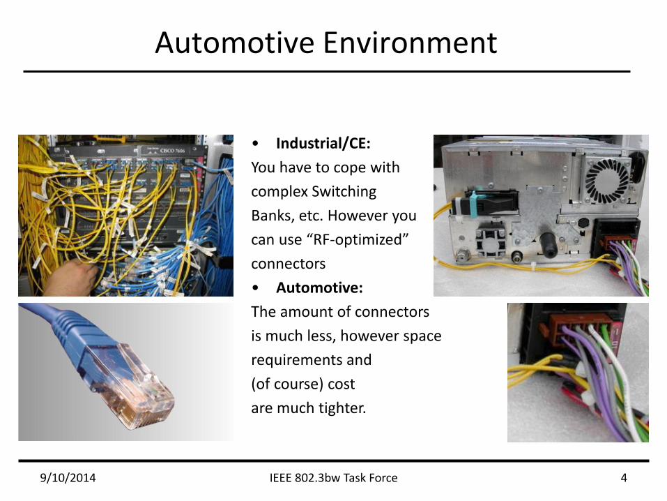
• Industrial/CE:
You have to cope with
complex Switching
Banks, etc. However you
can use “RF-optimized”
connectors
• Automotive:
The amount of connectors
is much less, however space
requirements and
(of course) cost
are much tighter.
Automotive Environment
9/10/2014 IEEE 802.3bw Task Force 4
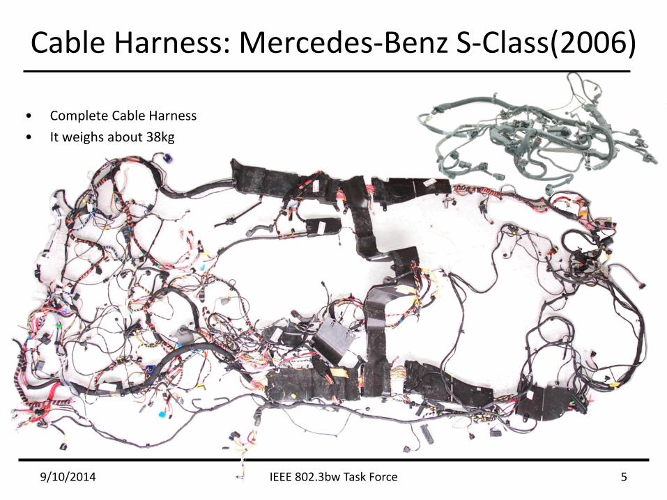
Cable Harness: Mercedes-Benz S-Class(2006)
• Complete Cable Harness
• It weighs about 38kg
9/10/2014
IEEE 802.3bw Task Force 5
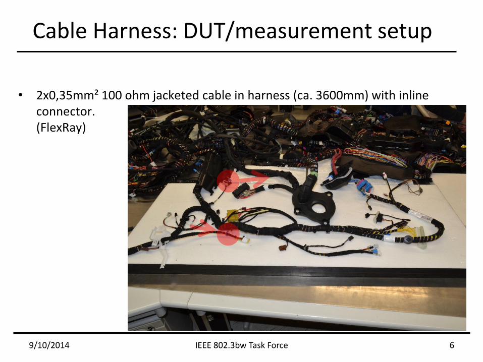
Cable Harness: DUT/measurement setup
• 2x0,35mm² 100 ohm jacketed cable in harness (ca. 3600mm) with inline connector. (FlexRay)
9/10/2014
IEEE 802.3bw Task Force 6
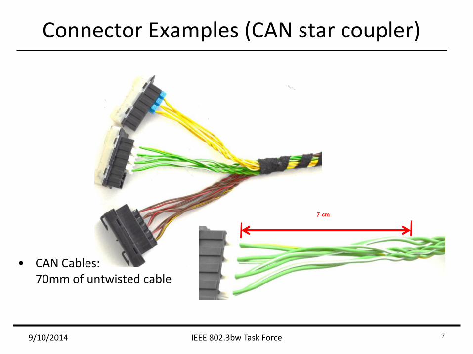
Connector Examples (CAN star coupler)
• CAN Cables: 70mm of untwisted cable
9/10/2014 IEEE 802.3bw Task Force 7
7 cm
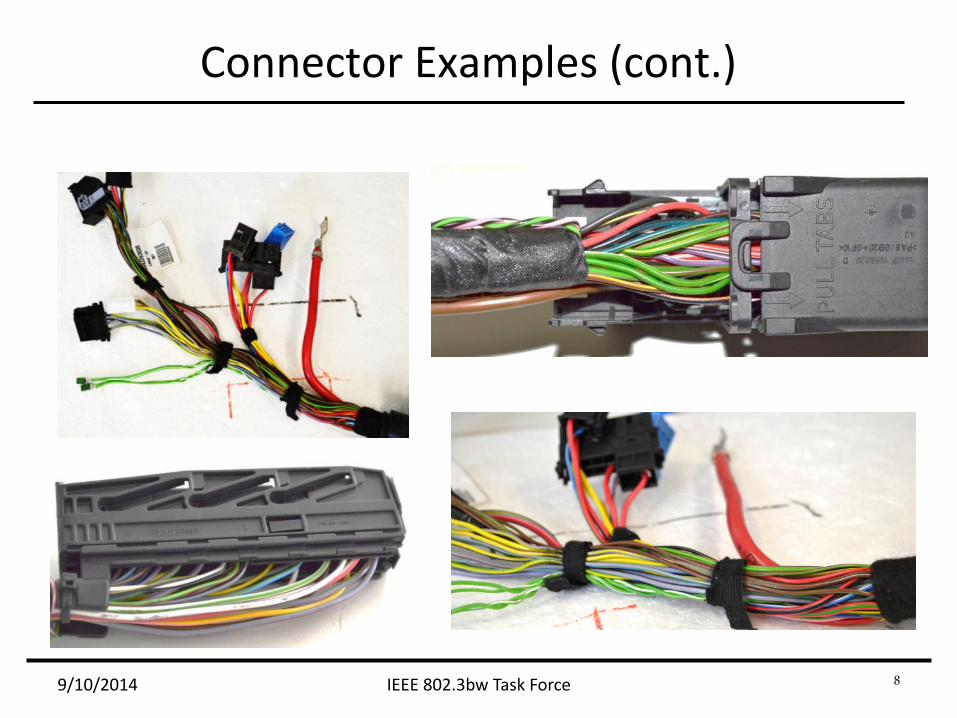
Connector Examples (cont.)
9/10/2014
8 IEEE 802.3bw Task Force
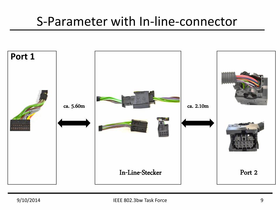
S-Parameter with In-line-connector
Port 1
9/10/2014
IEEE 802.3bw Task Force 9
In-Line-Stecker Port 2
ca. 5.60m ca. 2.10m

Cable Harness: DUT/measurement setup
• Messung mit VNWA:
9/10/2014
IEEE 802.3bw Task Force 10
Connector1/Jacketed Cable Connector2 inline
Test adapter (as these were older measurements the test adapter is maybe not perfect…) • Direct connection to GND plane. • SMA heads soldered to Pins which are plugged into
harness header. • Complete harness on GND plane. • No special treating of harness and assemblies to
achieve high symmetry
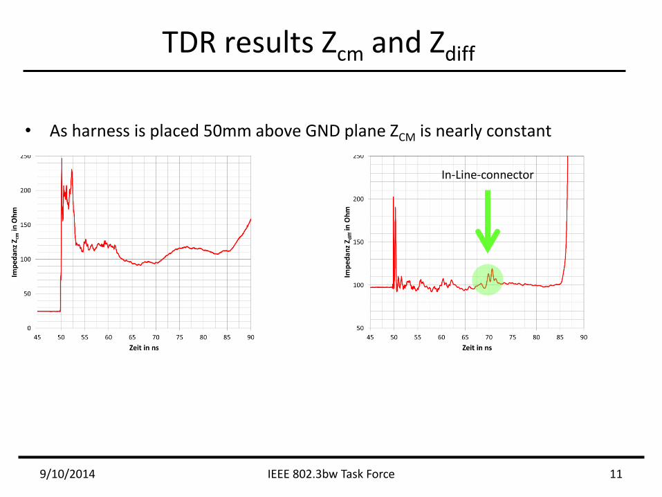
TDR results Zcm and Zdiff
• As harness is placed 50mm above GND plane ZCM is nearly constant
9/10/2014
IEEE 802.3bw Task Force 11
In-Line-connector
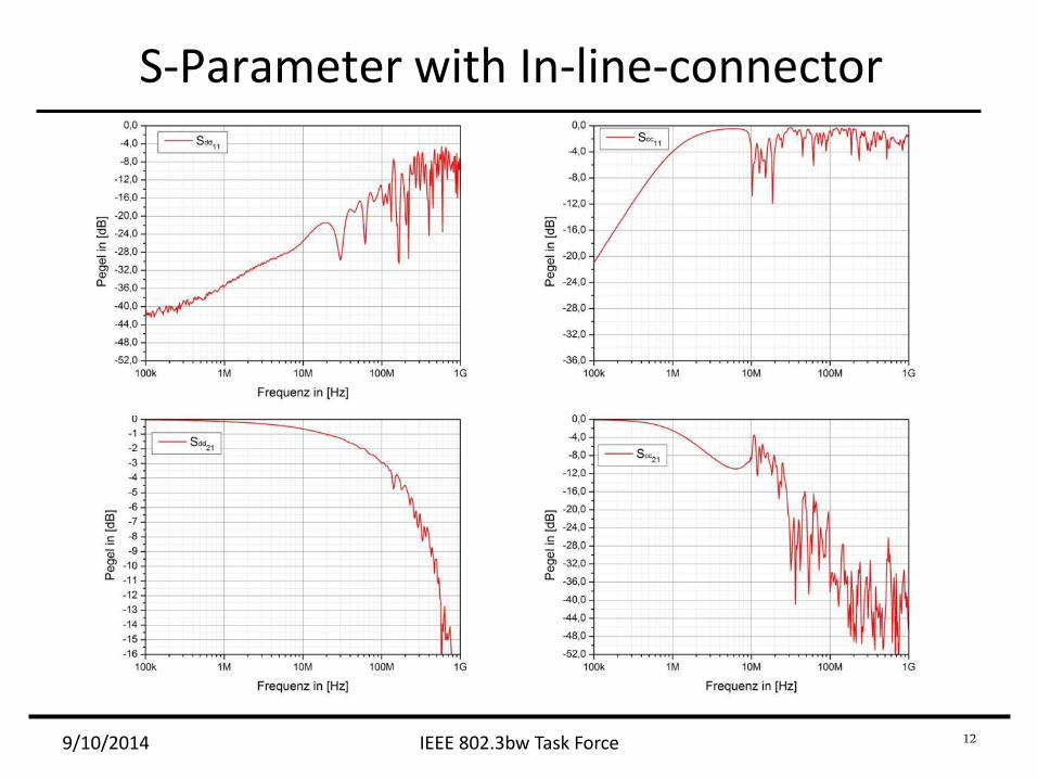
S-Parameter with In-line-connector
9/10/2014
IEEE 802.3bw Task Force 12
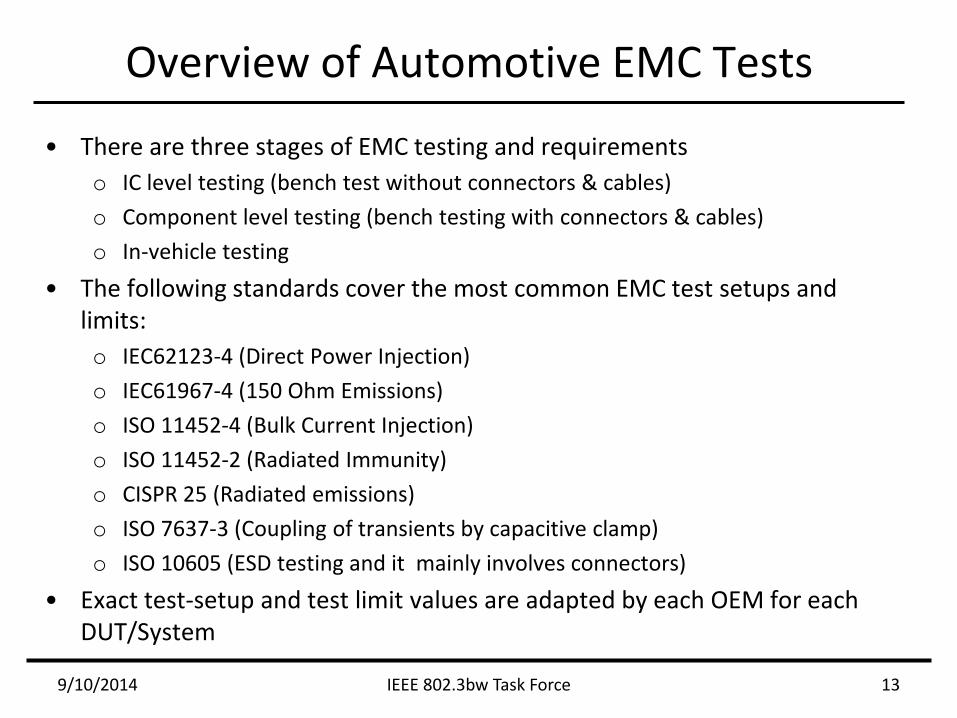
Overview of Automotive EMC Tests
• There are three stages of EMC testing and requirements
o IC level testing (bench test without connectors & cables)
o Component level testing (bench testing with connectors & cables)
o In-vehicle testing
• The following standards cover the most common EMC test setups and limits:
o IEC62123-4 (Direct Power Injection)
o IEC61967-4 (150 Ohm Emissions)
o ISO 11452-4 (Bulk Current Injection)
o ISO 11452-2 (Radiated Immunity)
o CISPR 25 (Radiated emissions)
o ISO 7637-3 (Coupling of transients by capacitive clamp)
o ISO 10605 (ESD testing and it mainly involves connectors)
• Exact test-setup and test limit values are adapted by each OEM for each DUT/System
9/10/2014 IEEE 802.3bw Task Force 13

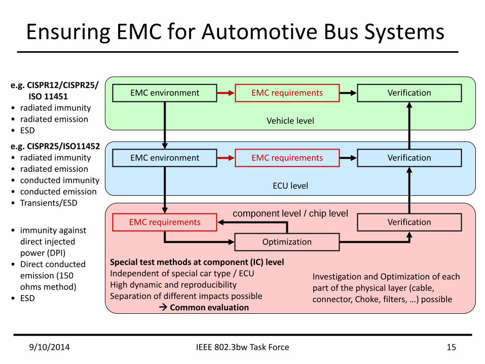
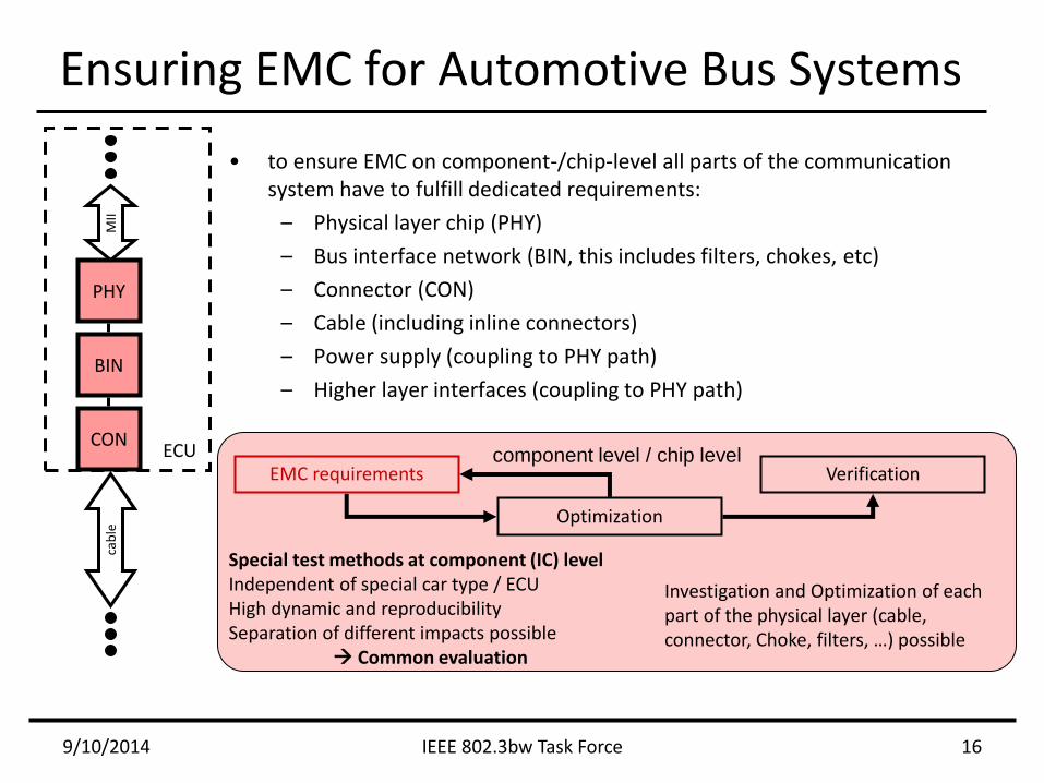
Ensuring EMC for Automotive Bus Systems
9/10/2014 IEEE 802.3bw Task Force 14
component level / chip level
EMC requirements
Optimization
Verification
Special test methods at component (IC) level Independent of special car type / ECU High dynamic and reproducibility Separation of different impacts possible Common evaluation
Derivation of
test procedures and correct disturbance
levels
as well as
corresponding requirements
and limits
Vehicle level
ECU level
EMC environment
EMC environment EMC requirements
EMC requirements Verification
Verification
Investigation and Optimization of each part of the physical layer (cable, connector, Choke, filters, …) possible
component level / chip level
Ensuring EMC for Automotive Bus Systems
9/10/2014 IEEE 802.3bw Task Force 15
Vehicle level
ECU level
EMC environment
EMC environment
EMC requirements
EMC requirements
EMC requirements
Optimization
Verification
Verification
Verification
Special test methods at component (IC) level Independent of special car type / ECU High dynamic and reproducibility Separation of different impacts possible Common evaluation
e.g. CISPR12/CISPR25/ ISO 11451
• radiated immunity • radiated emission • ESD
e.g. CISPR25/ISO11452 • radiated immunity • radiated emission • conducted immunity • conducted emission • Transients/ESD
• immunity against
direct injected power (DPI)
• Direct conducted emission (150 ohms method)
• ESD
Investigation and Optimization of each part of the physical layer (cable, connector, Choke, filters, …) possible
component level / chip level
Ensuring EMC for Automotive Bus Systems
• to ensure EMC on component-/chip-level all parts of the communication system have to fulfill dedicated requirements:
– Physical layer chip (PHY)
– Bus interface network (BIN, this includes filters, chokes, etc)
– Connector (CON)
– Cable (including inline connectors)
– Power supply (coupling to PHY path)
– Higher layer interfaces (coupling to PHY path)
9/10/2014 IEEE 802.3bw Task Force 16
EMC requirements
Optimization
Verification
Special test methods at component (IC) level Independent of special car type / ECU High dynamic and reproducibility Separation of different impacts possible Common evaluation
PHY
MII
BIN
CON
cab
le
ECU
Investigation and Optimization of each part of the physical layer (cable, connector, Choke, filters, …) possible
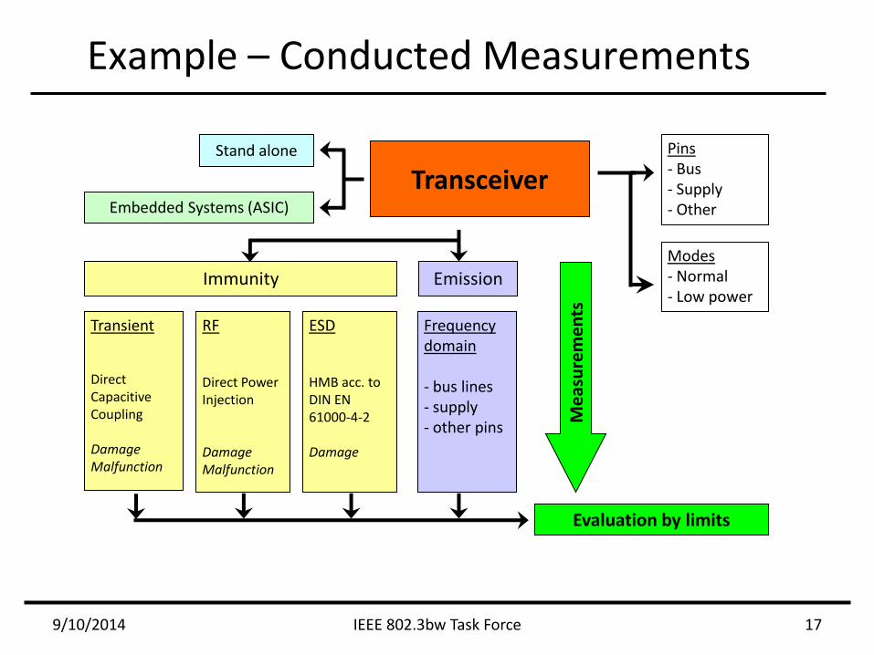
Example – Conducted Measurements
9/10/2014 IEEE 802.3bw Task Force 17
Transceiver Embedded Systems (ASIC)
Modes - Normal - Low power
Emission
Transient Direct Capacitive Coupling Damage Malfunction
RF Direct Power Injection Damage Malfunction
ESD HMB acc. to DIN EN 61000-4-2 Damage
Frequency domain - bus lines - supply - other pins
Stand alone Pins - Bus - Supply - Other
Immunity
Evaluation by limits
Me
asu
rem
en
ts
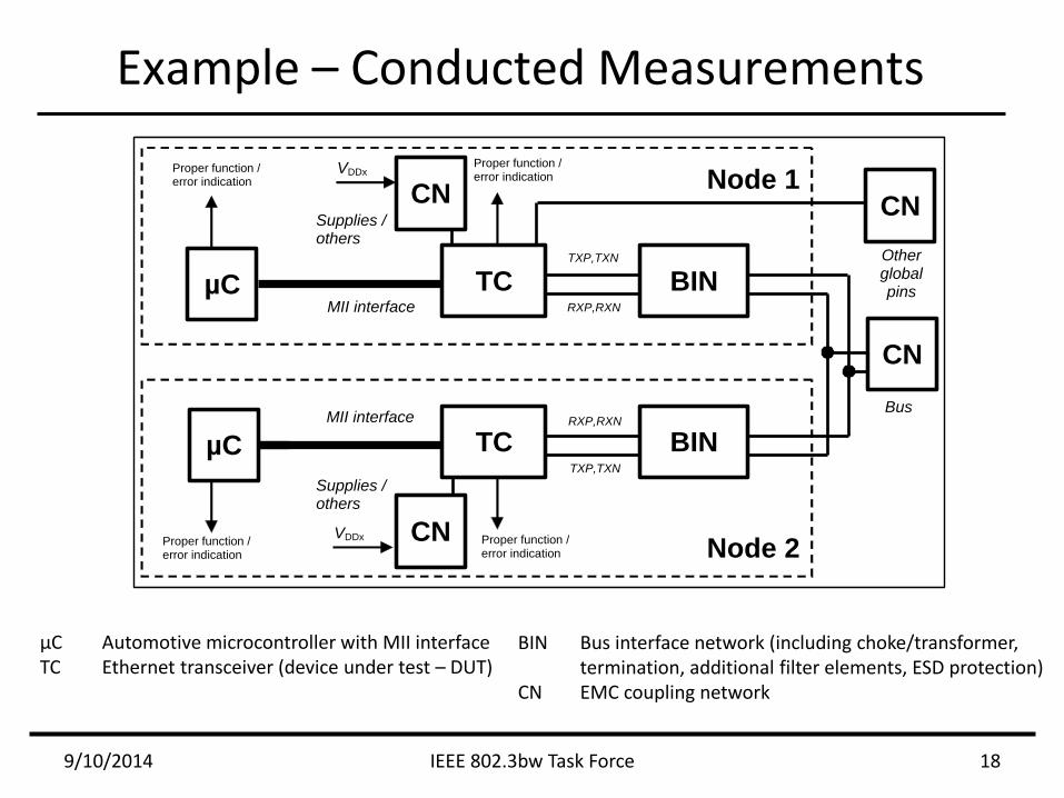
Example – Conducted Measurements
9/10/2014
IEEE 802.3bw Task Force 18
CN
Node 2
Bus
Proper function / error indication Node 1
TC µC BIN MII interface
TXP,TXN
TC BIN MII interface
CN
CN Supplies / others
Supplies / others
VDDx
VDDx
Proper function / error indication
Proper function / error indication
Proper function / error indication
RXP,RXN
TXP,TXN
RXP,RXN
CN
Other global pins
µC
BIN Bus interface network (including choke/transformer, termination, additional filter elements, ESD protection) CN EMC coupling network
µC Automotive microcontroller with MII interface TC Ethernet transceiver (device under test – DUT)
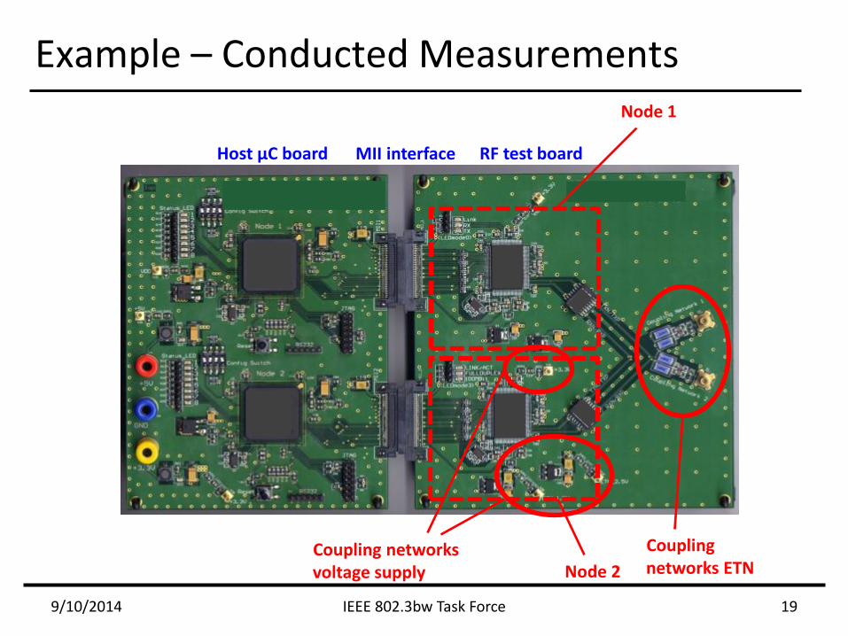
Example – Conducted Measurements
9/10/2014
IEEE 802.3bw Task Force 19
Host µC board RF test board MII interface
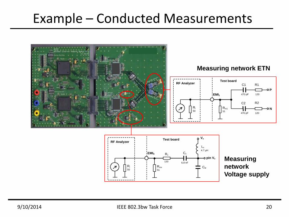
Coupling networks ETN
Coupling networks voltage supply
Node 1
Node 2
Example – Conducted Measurements
9/10/2014
IEEE 802.3bw Task Force 20
EMI1
RF Analyzer Test board
Ri 50
Rm1 51
120
P
N
470 pF
C1
C2
R1
R2
120 470 pF
EMIX
RF Analyzer Test board
120
pin Vx Rx
Ri 50
Rmx 51
6.8 nF
Cx
Cbl
4.7 µH
Vx
Lx
Measuring network ETN
Measuring
network
Voltage supply
Example – Conducted Measurements
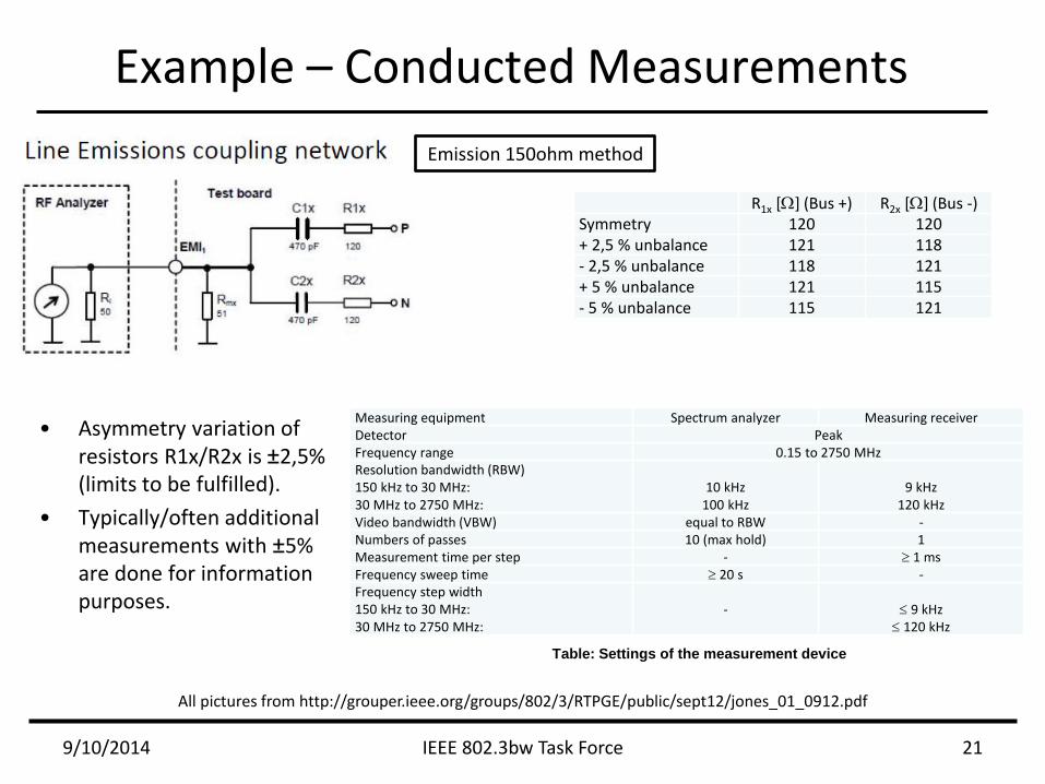
• Asymmetry variation of resistors R1x/R2x is ±2,5% (limits to be fulfilled).
• Typically/often additional measurements with ±5% are done for information purposes.
9/10/2014
IEEE 802.3bw Task Force 21
All pictures from http://grouper.ieee.org/groups/802/3/RTPGE/public/sept12/jones_01_0912.pdf
R1x [] (Bus +) R2x [] (Bus -) Symmetry 120 120
+ 2,5 % unbalance 121 118
- 2,5 % unbalance 118 121
+ 5 % unbalance 121 115
- 5 % unbalance 115 121
Measuring equipment Spectrum analyzer Measuring receiver Detector Peak
Frequency range 0.15 to 2750 MHz Resolution bandwidth (RBW) 150 kHz to 30 MHz: 30 MHz to 2750 MHz:
10 kHz
100 kHz
9 kHz
120 kHz Video bandwidth (VBW) equal to RBW - Numbers of passes 10 (max hold) 1
Measurement time per step - 1 ms Frequency sweep time 20 s - Frequency step width 150 kHz to 30 MHz: 30 MHz to 2750 MHz:
-
9 kHz 120 kHz
Table: Settings of the measurement device
Emission 150ohm method
Example – Conducted Measurements
9/10/2014
IEEE 802.3bw Task Force 22
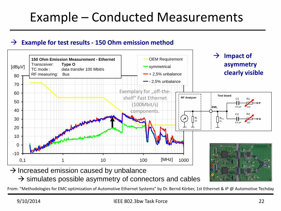
Example for test results - 150 Ohm emission method
-10
0
10
20
30
40
50
60
70
80
0,1 1 10 100 1000
OEM Requirement
symmetrical
+ 2,5% unbalance
- 2,5% unbalance
150 Ohm Emission Measurement - Ethernet
Transceiver: Type O
TC mode : data transfer 100 Mbit/s
RF measuring: Bus
[MHz]
[dBµV]
EMI1
RF Analyzer Test board
Ri 50
Rm1 51
120
P
N
470 pF
C1
C2
R1
R2
120 470 pF
Increased emission caused by unbalance
simulates possible asymmetry of connectors and cables
Impact of asymmetry clearly visible
From: “Methodologies for EMC optimization of Automotive Ethernet Systems” by Dr. Bernd Körber, 1st Ethernet & IP @ Automotive Techday
Exemplary for „off-the-shelf“ Fast Ethernet
(100Mbit/s) components.
Example – Conducted Measurements
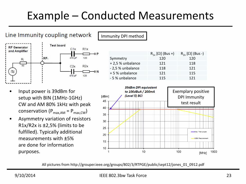
• Input power is 39dBm for setup with BIN (1MHz-1GHz) CW and AM 80% 1kHz with peak conservation (Pmax,AM = Pmax,CW)
• Asymmetry variation of resistors R1x/R2x is ±2,5% (limits to be fulfilled). Typically additional measurements with ±5% are done for information purposes.
9/10/2014
IEEE 802.3bw Task Force 23
All pictures from http://grouper.ieee.org/groups/802/3/RTPGE/public/sept12/jones_01_0912.pdf
R1x [] (Bus +) R2x [] (Bus -) Symmetry 120 120 + 2,5 % unbalance 121 118 - 2,5 % unbalance 118 121 + 5 % unbalance 121 115 - 5 % unbalance 115 121
Immunity DPI method
Exemplary positive DPI Immunity
test result
Example – Conducted Measurements
9/10/2014
IEEE 802.3bw Task Force 24
10
15
20
25
30
35
40
45
1 10 100 1000
Max Test power
Limit class A
Limit class B
symmetrical
+ 2,5 % unbalanced
- 2,5 % unbalanced
[MHz]
[dBm]
DPI Test - Ethernet
Transceiver: Type X
TC mode : data transfer 100 Mbit/s
RF coupling: Bus, AM
85
90
95
100
105
110
1 10 100 1000
Limit /max test level
Wihtout In-line connector
In-line connector (1)
In-line connector (2)
In-line connector (3)
[MHz]
[dBµA]
BCI Test - Ethernet
Transceiver: Type X
TC mode : data transfer 100 Mbit/s
RF coupling: Bus, CW
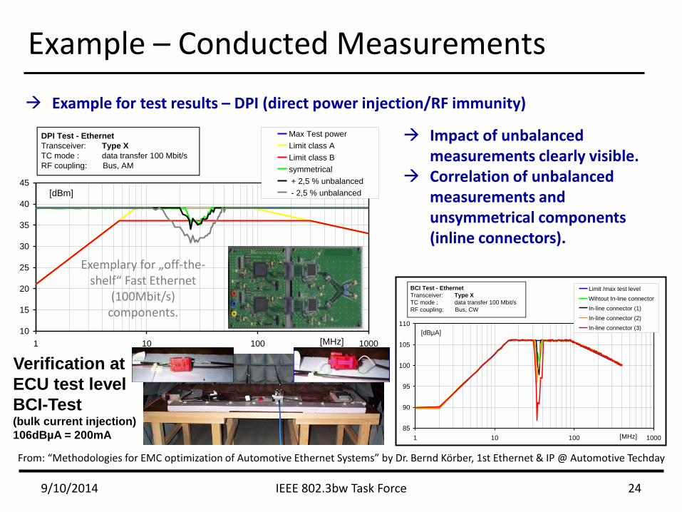
Verification at
ECU test level
BCI-Test (bulk current injection)
106dBµA = 200mA
Example for test results – DPI (direct power injection/RF immunity)
From: “Methodologies for EMC optimization of Automotive Ethernet Systems” by Dr. Bernd Körber, 1st Ethernet & IP @ Automotive Techday
Impact of unbalanced measurements clearly visible.
Correlation of unbalanced measurements and unsymmetrical components (inline connectors).
Exemplary for „off-the-shelf“ Fast Ethernet
(100Mbit/s) components.
Example – Conducted Measurements
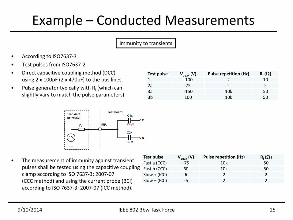
• According to ISO7637-3
• Test pulses from ISO7637-2
• Direct capacitive coupling method (DCC) using 2 x 100pF (2 x 470pF) to the bus lines.
• Pulse generator typically with Ri (which can slightly vary to match the pulse parameters).
• The measurement of immunity against transient pulses shall be tested using the capacitive coupling clamp according to ISO 7637-3: 2007-07 (CCC method) and using the current probe (BCI) according to ISO 7637-3: 2007-07 (ICC method).
9/10/2014 IEEE 802.3bw Task Force 25
Test pulse Vpeak (V) Pulse repetition (Hz) Ri () 1 -100 2 10 2a 75 2 2 3a -150 10k 50 3b 100 10k 50
Test pulse Vpeak (V) Pulse repetition (Hz) Ri () Fast a (CCC) -75 10k 50 Fast b (CCC) 60 10k 50 Slow + (ICC) 6 2 2 Slow – (ICC) -6 2 2
Immunity to transients
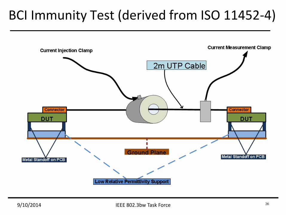
BCI Immunity Test (derived from ISO 11452-4)
9/10/2014
IEEE 802.3bw Task Force 26
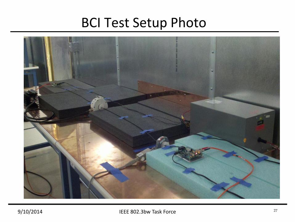
BCI Test Setup Photo
9/10/2014
IEEE 802.3bw Task Force 27
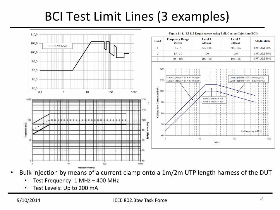
BCI Test Limit Lines (3 examples)
9/10/2014 IEEE 802.3bw Task Force 28
• Bulk injection by means of a current clamp onto a 1m/2m UTP length harness of the DUT • Test Frequency: 1 MHz – 400 MHz • Test Levels: Up to 200 mA
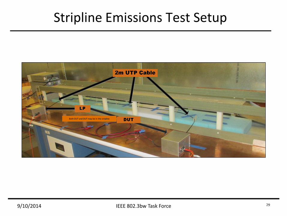
Stripline Emissions Test Setup
9/10/2014 IEEE 802.3bw Task Force
Both DUT and DUT may be in the stripline
29
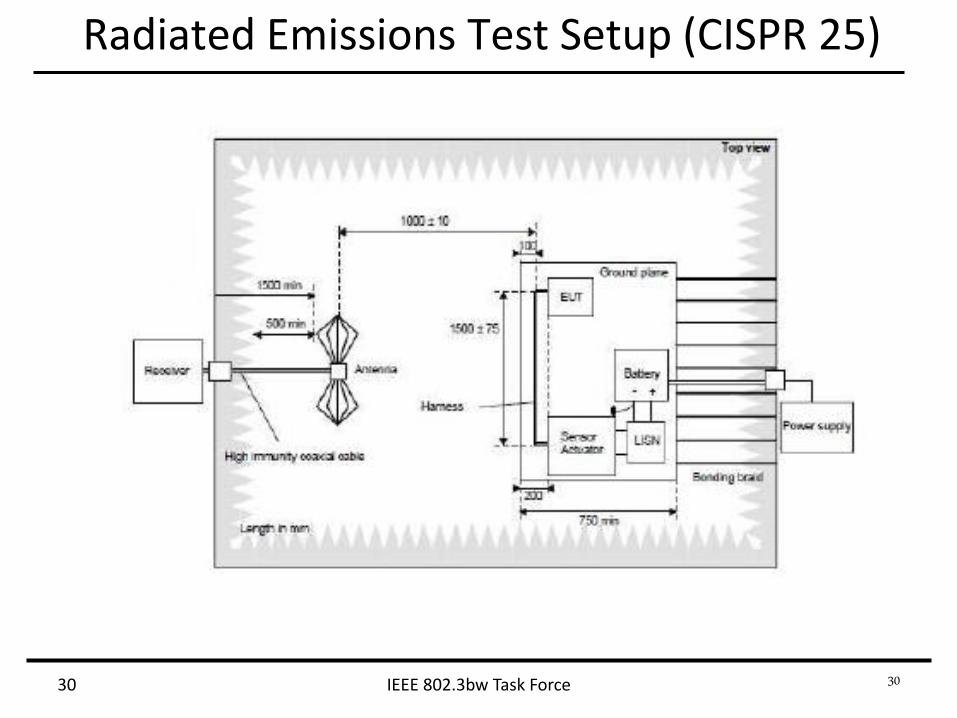
Radiated Emissions Test Setup (CISPR 25)
30 IEEE 802.3bw Task Force 30
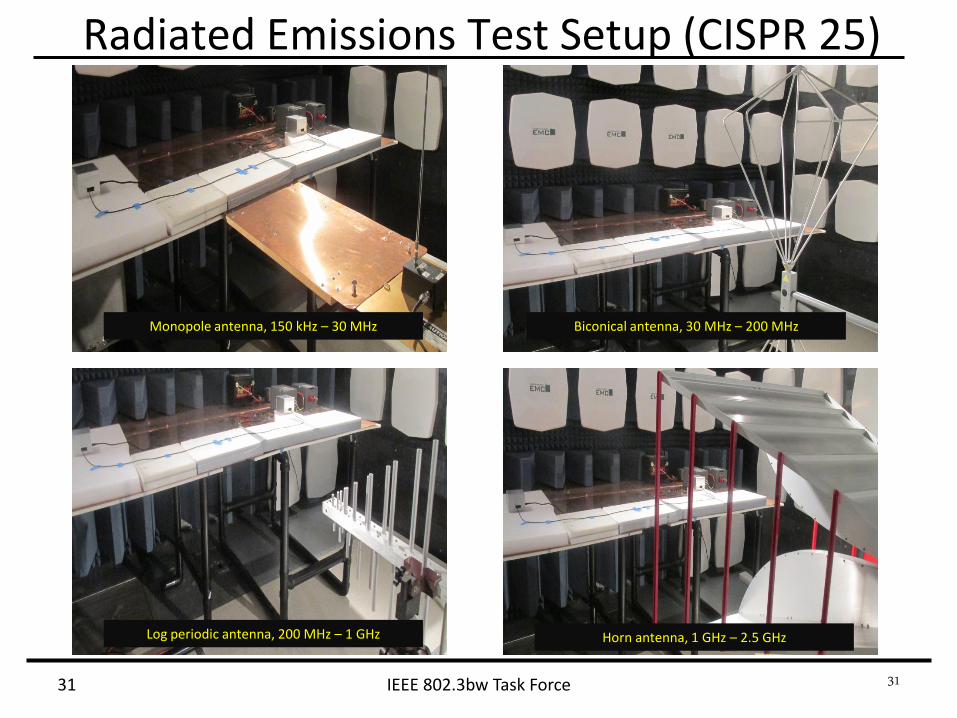
Radiated Emissions Test Setup (CISPR 25)
31 IEEE 802.3bw Task Force
Monopole antenna, 150 kHz – 30 MHz Biconical antenna, 30 MHz – 200 MHz
Log periodic antenna, 200 MHz – 1 GHz Horn antenna, 1 GHz – 2.5 GHz
31
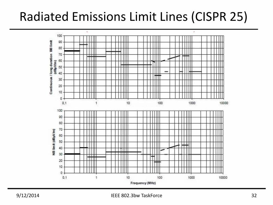
Radiated Emissions Limit Lines (CISPR 25)
9/12/2014 IEEE 802.3bw TaskForce 32
Summary
• This presentation gives a brief overview of Automotive EMC environment and existing relevant tests
• The shown pictures are a few examples of many different automotive cable harness options
• The shown s-Parameter measurements are also a few examples (and by way not the “worst case“) of how an automotive channel could look like.
• Automotive channels have a wide variety and the channel model needs to include these parameter variations
• The test methods are standardized but the limit lines can vary among different OEMS with somewhat similar values
9/12/2014 IEEE 802.3bw TaskForce 33

Appendix:
For informational purposes, please also review the following 1000BASE-T1 documents from the study group phase: • http://grouper.ieee.org/groups/802/3/RTPGE/public/may12/buntz_01_0512.pdf
• http://grouper.ieee.org/groups/802/3/RTPGE/public/may12/hogenmuller_01_0512.pdf
• http://grouper.ieee.org/groups/802/3/RTPGE/public/july12/buntz_03_0712.pdf
• http://grouper.ieee.org/groups/802/3/RTPGE/public/july12/hogenmuller_01a_0712.pdf
• http://grouper.ieee.org/groups/802/3/RTPGE/public/july12/hogenmuller_02a_0712.pdf
• http://grouper.ieee.org/groups/802/3/RTPGE/public/july12/zinner_02_0712.pdf
• http://grouper.ieee.org/groups/802/3/RTPGE/public/sept12/jones_01_0912.pdf
• http://grouper.ieee.org/groups/802/3/RTPGE/public/nov12/buntz_01_1112_rtpge.pdf
• http://www.ieee802.org/3/RTPGE/public/adhoc/buntz_01_1112_rtpge.pdf
• http://grouper.ieee.org/groups/802/3/RTPGE/public/nov12/pischl_01_1112_rtpge.pdf
Also following further information could be helpful: • http://www.fordemc.com/
• http://www.ieee802.org/3/bp/public/jan13/tazebay_3bp_01a_0113.pdf
• http://www.ieee802.org/3/bp/public/may13/tazebay_3bp_01_0513.pdf
• http://www.ieee802.org/3/bp/public/nov13/Chini_Tazebay_3bp_02a_1113.pdf
• http://www.ieee802.org/3/bp/public/mar14/EMCnoise_ad_hoc_3bp_01_0314.pdf
9/12/2014 IEEE 802.3bw TaskForce 34