Embed Size (px)
Citation preview
EFFECTIVE NEW TECHNOLOGIES FOR THE
ASSESSMENT OF COMPLIANCE WITH THE BALLAST
WATER MANAGEMENT CONVENTION
A Research and Development Project financed by the Federal Maritime and Hydrographic Agency of Germany
Interims Report
June 2013
WHEN YOU NEED TO BE SURE
2
TABLE OF CONTENT
EXECUTIVE SUMMARY .......................................................................................................................................... 4
LIST OF ABBREVIATIONS ..................................................................................................................................... 5
1 INTRODUCTION .............................................................................................................................................. 6
2 GENERAL PROJECT FRAME ........................................................................................................................ 6
3 PROJECT OBJECTIVES ................................................................................................................................ 6
3.1 MAJOR PROJECT OBJECTIVES ...................................................................................................................... 6
3.2 PROJECT SECTORS AND TASKS .................................................................................................................... 6
4 CO-OPERATION PARTNERS......................................................................................................................... 7
5 GENERAL ASPECTS OF BALLAST WATER ................................................................................................ 7
5.1 CHARACTERISTICS OF BALLAST WATER PIPE SYSTEMS ON BOARD SHIPS ......................................................... 8
6 THE IMO BALLAST WATER REGULATIONS ............................................................................................... 8
6.1 THE IMO REGULATIONS FOR BALLAST WATER SAMPLING .............................................................................. 9
6.2 THE IMO BALLAST WATER DISCHARGE STANDARD ....................................................................................... 9
7 GENERAL ASPECTS OF BALLAST WATER SAMPLING .......................................................................... 10
7.1 REPRESENTATIVENESS OF BALLAST WATER SAMPLING ............................................................................... 10
7.2 THE ISOKINETIC PRINCIPLE ....................................................................................................................... 10
8 GENERAL ASPECTS OF BALLAST WATER ANALYSIS ........................................................................... 11
9 THE PROJECT WORKBASE ........................................................................................................................ 12
10 PROJECT ACHIEVEMENTS TO DATE ........................................................................................................ 14
10.1 SAMPLING OF BALLAST WATER ................................................................................................................. 14
10.1.1 Sampling Ports ........................................................................................................................... 14
10.1.2 On boardsampling system: open and closed systems................................................................ 20
10.1.3 The SGS Mobile sampling system Prototype 01 ........................................................................ 21
10.1.4 Mobile sampling system Prototype 01: Results .......................................................................... 26
10.2 ON BOARD ANALYSIS OF BALLAST WATER ................................................................................................. 29
10.2.1 General considerations ............................................................................................................... 29
10.2.2 Fluorescein-Diacetate Fluorometry – FDA ................................................................................. 31
10.2.3 Pulse Amplitude Modulation Fluorometry – PAM ....................................................................... 32
10.2.4 Adenosin-Triphosphate Fluorometry - ATP ................................................................................ 32
10.2.5 Fluorescence-in-situ Hybridization - FISH .................................................................................. 35
10.2.6 Analytical methods for rapid on board compliance testing : safety issues .................................. 35
10.2.7 Analytical methods for rapid on board compliance testing .......................................................... 36
11 COMMENTS .................................................................................................................................................. 36
11.1 APPLICATION RANGE OF THE SAMPLING SYSTEM PROTOTYPE 01 ................................................................. 36
11.2 THE ISOKINETIC PRINCIPLE ....................................................................................................................... 38
12 CONTINUATION OF PROJECT ACTIVITIES ............................................................................................... 39
12.1 ISOKINETIC SAMPLING PORTS ................................................................................................................... 39
12.2 SGS BALLAST WATER SAMPLING SYSTEM PROTOTYPE 01 .......................................................................... 39
12.3 ANALYTICAL METHODS .............................................................................................................................. 40
12.4 OTHERS .................................................................................................................................................. 40
13 ANNEX .......................................................................................................................................................... 41

3
13.1 PROJECT CO-OPERATION PARTNERS ......................................................................................................... 41
13.2 PROJECT SECTORS AND TASKS .................................................................................................................. 42
4
EXECUTIVE SUMMARY
A transportable, isokinetic back flush sampling system has been
designed and tested for on board sampling of ballast water. The
sampling system is able to generate representative samples of ballast
water in terms of plankton organism concentration and de-ballast
procedures. Providing a universal sampling port with different
isokinetic pipes, the system can be flanged to all pipe systems on all
ships and is ready for application.
Several new analytical methods have been developed for rapid, on
board analysis of the ballast water on ships indicating the “gross
exceedance” of the standard values for the three target organism size
classes defined by the IMO within the frame of the ballast water
management convention. All of the new methods are ready for
application with beta test kits already available.
5
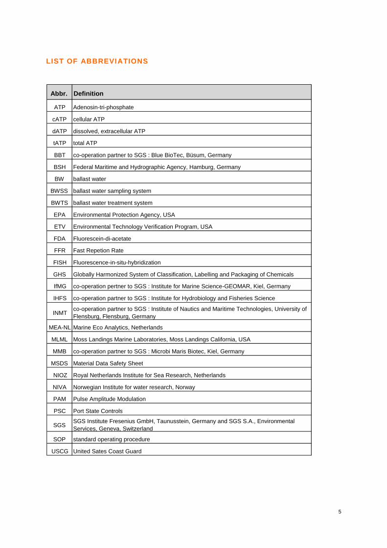
LIST OF ABBREVIATIONS
Abbr. Definition
ATP Adenosin-tri-phosphate
cATP cellular ATP
dATP dissolved, extracellular ATP
tATP total ATP
BBT co-operation partner to SGS : Blue BioTec, Büsum, Germany
BSH Federal Maritime and Hydrographic Agency, Hamburg, Germany
BW ballast water
BWSS ballast water sampling system
BWTS ballast water treatment system
EPA Environmental Protection Agency, USA
ETV Environmental Technology Verification Program, USA
FDA Fluorescein-di-acetate
FFR Fast Repetion Rate
FISH Fluorescence-in-situ-hybridization
GHS Globally Harmonized System of Classification, Labelling and Packaging of Chemicals
IfMG co-operation pertner to SGS : Institute for Marine Science-GEOMAR, Kiel, Germany
IHFS co-operation partner to SGS : Institute for Hydrobiology and Fisheries Science
INMT co-operation partner to SGS : Institute of Nautics and Maritime Technologies, University of Flensburg, Flensburg, Germany
MEA-NL Marine Eco Analytics, Netherlands
MLML Moss Landings Marine Laboratories, Moss Landings California, USA
MMB co-operation partner to SGS : Microbi Maris Biotec, Kiel, Germany
MSDS Material Data Safety Sheet
NIOZ Royal Netherlands Institute for Sea Research, Netherlands
NIVA Norwegian Institute for water research, Norway
PAM Pulse Amplitude Modulation
PSC Port State Controls
SGS SGS Institute Fresenius GmbH, Taunusstein, Germany and SGS S.A., Environmental Services, Geneva, Switzerland
SOP standard operating procedure
USCG United Sates Coast Guard
6
1 INTRODUCTION
This interims report presents the fact and findings of the research and development project
“Effective new Technologies for the Assessment of Compliance with the Ballast Water
Management Convention” up to June 2013.
The detailed description of the project results to date are headed by general considerations
regarding ballast water, ballast water pipe systems, ballast water sampling and ballast water
analysis from which the report tries to draw a picture of the challenges, generated by the
major project objectives.
A separate chapter describes the project activities still necessary to successfully finalize the
project.
2 GENERAL PROJECT FRAME
In early 2012 the SGS Institute Fresenius GmbH, Taunusstein, Germany, was charged
by the BSH to execute in co-operation with the Moss Landings Marine Laboratories,
Moss Landings, California, USA, the project “Effective new Technologies for the
Assessment of Compliance with the Ballast Water Management Convention”.
The overall project management was given to SGS and in line with the overall project
objectives the different tasks to be completed within the frame of this project were
distributed to both of the project partners.
On the side of SGS the project is managed by Dr. Lothar Schillak, marine biologist, and
on the side of the MLML, Prof. Dr. Nick Welschmeyer is responsible for the execution
of the project tasks.
3 PROJECT OBJECTIVES
3.1 MAJOR PROJECT OBJECTIVES
The major objectives of the project are twofold:
(1) The development of an on board ballast water sampling system, which allows
for representative sampling from BW pipe systems installed on ships.
(2) The development of rapid, analytical on board methods, which generate reliable
data that indicatively define “Compliance” or “gross NON-Compliance” of ballast
water treatment systems in line with the “International Convention for the
Control and Management of Ship’s Ballast Water and Sediments (BWM)” set up
by the IMO in 2004.
3.2 PROJECT SECTORS AND TASKS
Derived from the major project objectives a list of detailed project sectors and tasks
was agreed between the BSH and the project management.
7
Annex 13.2, page 42 displays the single sectors and tasks and indicates the
responsible project partner.
Regarding the major project objective under para 3.1 (2) (development of rapid,
analytical on board methods) the BSH pre-defined the FDA Fluorometry and the Pulse-
Amplitude-Modulation Fluorometry as analytical methods, which should be further
developed as potential rapid, on board methods.
After consultations between the BSH and the project management it was mutually
agreed, that the spectrum of analytical methods to be further developed for rapid on
board BW analysis should be enlarged by (i) the ATP Fluorometry as well as by (ii) the
FISH Microscopy.
4 CO-OPERATION PARTNERS
Following the complex structure of the project and seen to the manifold impacts the
facts and findings of the project would possibly generate on the international sector of
ballast water management, it was decided to select institutes, companies and experts
as co-operation partners covering project aspects, which stand outside the SGS field of
expertise.
Annex 13.1, page 41, presents the list of co-operation partners, which contributed to
this project.
5 GENERAL ASPECTS OF BALLAST WATER
Natural seawater is taken into the ship via coarse filters (mesh size 2mm) by seawater
pumps and a very complex system of pipes flushes the seawater into a number of
tanks with various volume and shape, distributed all around the ship’s hull. Entering the
tanks the natural seawater is turned into an artificial water body, in which most of the
natural regulatory biological, physical, chemical and microbiological processes are
severely inhibited or even simply cease to exist. Disregarding the alterations in the
natural ecological processes in the ballast water tanks, many marine organisms prove
to be able and establish populations of considerable size under these sub-optimal
ecological conditions.
When re-discharged into the marine environment different to the original environment
these populations in the ballast water might invade coastal regions and by establishing
new populations they might shift the local ecological equilibrium by stepping into a
spatial and food competition with the autochtonous species, sometimes causing
enormous economic damage to entire coastal areas.
By adequate treatment technologies applied during intake and re-discharge of the
ballast water the detrimental impacts from invasive species on the local marine
environment can be minimized, if not eliminated.
8
5.1 CHARACTERISTICS OF BALLAST WATER PIPE SYSTEMS ON BOARD SHIPS
Ballast water in ships is used to balance the ship during loading and un-loading
processes as well as to stabilize the ship during rough weather conditions.
It is the character of a ship that decides on the necessary dimensions of the seawater
pump, the number of BW tanks and on the dimensions of the ballast water pipes, too.
Since large cruise liners do not load and unload large volumes with heavy weight,
these ships have small ballast water tanks, small pipes and seawater pumps with a low
capacity.
In contrary, e.g. liquid gas tankers, quickly load and unload large volumes with heavy
weight and as a consequence these ships have many ballast water tanks, large pipes
and seawater pumps with a very high capacity.
The total volume of ballast water tanks on board ships ranges from 400m³ to
300.000m³, the dimension (inner diameter) of ballast water pipes ranges from 10cm to
80cm and the capacity of seawater pumps spreads from 100m³/h to 8000m³/h.
With these constellations the total time needed to take up ballast water or to de-ballast,
too, largely depends on the type of ship and ranges from a few hours to several days.
6 THE IMO BALLAST WATER REGULATIONS
To prevent ecological damage and economic losses generated by invasive species
introduced by discharged ballast water originating from different marine areas the
“International Convention for the Control and Management of Ship’s Ballast Water and
Sediments” of the IMO demands ballast water management to fulfil the D-2
performance standard. To date the main approach to achieve the requirements is the
installation of ballast water treatment system on board ships.
Some of the manifold regulations within the frame of this convention clearly address
the sampling and analysis of ballast water on board ships and define a discharge
standard for ballast water regarding, among others, the density of viable organisms in
the ballast water to be discharged.
The ensemble of these regulations for sampling/analysis and ballast water discharge
quality are published in different IMO documents :
(1) Guidelines for Ballast Water Sampling (G2), October 10th, 2008
(source: MEPC 58/23, Annex 3, Resolution MEPC.173/58) )
(2) Guidelines for Approval of Ballast Water Management Systems (G8), October 10th, 2008
(source: MEPC 58/23, Annex 4, Resolution MEPC.174(58) )
9
6.1 THE IMO REGULATIONS FOR BALLAST WATER SAMPLING
According to the documents listed above the major obligations for ballast water
sampling are these:
(1) The on board ballast water sampling has to be executed via an “L”-shaped,
isokinetic sampling port.
(2) The sampling ports have to be located as near to the on board discharge points
for ballast water as possible.
(3) The ballast water of all on board discharge points has to be sampled and
analyzed.
(4) The ballast water samples should have a large volume as indicated in IMO
Guideline G2 annex, para 6.2.5 and IMO Guideline G8 annex 4, para 2.3.31 .
(5) The on board ballast water sampling has to cover the entire period of de-
ballasting.
(6) In case of filtration steps as integral parts of the sampling procedures for ballast
waters adequate filter materials have to be used, the mesh size of which should
not exceed 50µm in diameter or diagonal for the IMO target organism size class
of plankton organisms >50µm and should not exceed 10µm in diameter for the
IMO target organism size class of plankton organisms >10µm<50µm.
6.2 THE IMO BALLAST WATER DISCHARGE STANDARD
The regulations within the frame of the Ballast Water Management Convention define
three organism classes:
(1) Marine plankton organisms with a size of >50µm
(2) Marine plankton organisms with a size between >10µm and <50µm
(3) Marine bacteria (Escherichia coli, Enterococci and Vibrio cholera)
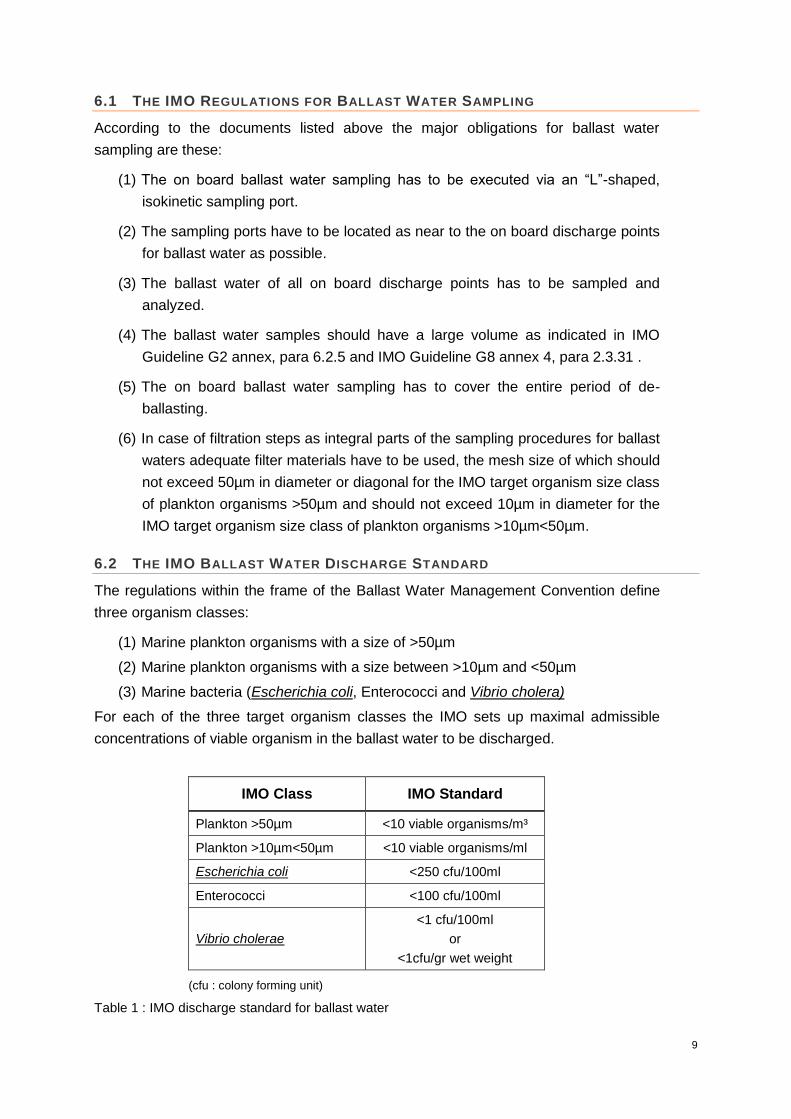
For each of the three target organism classes the IMO sets up maximal admissible
concentrations of viable organism in the ballast water to be discharged.
IMO Class IMO Standard
Plankton >50µm <10 viable organisms/m³
Plankton >10µm<50µm <10 viable organisms/ml
Escherichia coli <250 cfu/100ml
Enterococci <100 cfu/100ml
Vibrio cholerae
<1 cfu/100ml
or
<1cfu/gr wet weight
(cfu : colony forming unit)
Table 1 : IMO discharge standard for ballast water

10
7 GENERAL ASPECTS OF BALLAST WATER SAMPLING
7.1 REPRESENTATIVENESS OF BALLAST WATER SAMPLING
To execute on board ballast water sampling, the ballast water pipe system installed on
board has to provide an access to the ballast water flowing through the pipes by
bypassing the ballast water through small pipes, tubes or similar installations.
The ballast water taken via these sampling ports has to be of the same quality in terms
of total suspended solids and concentrations of marine organisms as the ballast water
in the main ballast water pipe system: the ballast water sample has to be
representative.
This representativeness is twofold. The ballast water sample has not only to be of the
same quality as the ballast water in the main ballast water pipe system in terms of
particulate matter (organisms, organic and inorganic matter) as expressed above, but it
should also reflect alterations in the quality of the ballast water across the entire period
of de-ballasting: the ballast water sample has to be representative in quality and in
time.
7.2 THE ISOKINETIC PRINCIPLE
The optimal design of a small pipe inserted into a main ballast water pipe system,
which ensures the highest representativeness for ballast water samples in terms of
quality and time, was intensively investigated by the aid of computational fluid
dynamics.
Although marine plankton organisms are naturally buoyant the isokinetic sampling of
ballast water represents the optimal way to generate representative samples. With
isokinetic sampling the flow velocity in the sampling (=isokinetic) pipe is the same as in
the main ballast water pipe. The diameter of the isokinetic sampling pipe is determined
by the equation below:
E1
(with Diso=diameter of isokinetic pipe; Qiso=flow rate in the isokinetic pipe; DM=diameter of main pipe; QM=flow rate in the main pipe)
In search for the optimal design of the isokinetic sampling pipe, the tests of numerous
variants defined a pipe placed concentrically in the centre of the main ballast water
pipe with its opening facing upstream as optimal, since it generates the best sampling
flow. The isokinetic sampling pipe may either by inserted as an “L” shaped bow or as a

11
straight pipe fixed by a flange through an bow of the main ballast water pipe (cf. figures
1 and 2, page 11).
Figure 1: “L”-shaped isokinetic sampling port
Figure 2: Straight isokinetic sampling port
8 GENERAL ASPECTS OF BALLAST WATER ANALYSIS
The detection of viable plankton organisms of the two IMO target organism size
classes listed above can be executed by traditional methods like microscopic counts, if
necessary preceded by vital staining to distinguish between viable and dead
organisms.
Marine bacteria in ballast water samples are detected by the traditional incubation
method on species and group specific media (agar).
ballast water main pipe
isokinetic sampling pipe length
ballast water main pipe
isokinetic sampling pipe ("L"- shape)
length
d1
d2

12
For all IMO target organism size classes it might possibly be necessary to condense
the ballast water by adequate filtration steps, also in respect to the IMO regulations for
ballast water sampling (cf. para 6, page 8).
However, these traditional methods are time consuming and for some methods require
the application of ecotoxic substances (i.e. stains). Especially in combination with the
IMO regulation for ballast water sampling (cf. para 6, page 8) the on board test of the
ballast water for compliance with the International Ballast Water Management
Convention might demand several days from sample to result also depending from the
type of vessel and the ballast water pipe system installed on board.
These time constraints combined to the traditional analytical methods, currently
available, trigger the demand for new, analytical methods, reducing the time from
sample to result down to preferably a few minutes.
The new analytical methods, which, on the one hand, generate rapid results, might, on
the other hand, possibly not be able to distinguish between 9 and 10 individuals for the
respective target plankton size class. However, by statistical considerations and in
order to keep to the short time from sample to result, these new rapid methods might
indicate just a “gross exceedance” in respect to the discharge standard set up by the
IMO.
In case the “rapid on board indicative compliance test” of the ballast water with the new
analytical methods reveals such a “gross exceedance” a “full scale, in depth, regulatory
analysis” of the ballast water in a landbased laboratory is regarded to be indispensible.
9 THE PROJECT WORKBASE
The Institute for Nautics and Maritime Technologies is part of the University of
Flensburg, Germany. The INMT runs a large testing site in the harbor of Flensburg,
Baltic Sea. The premises of the INMT harbor testing site provide in-house systems of
running seawater, which is taken from the nearby Flensburg Bight of the Baltic Sea.
Before entering the in-house pipe system the seawater is filtered by a commercial
seawater filter with a mesh size of 2mm.
A part from several workshops and huge halls for testing of 1:1 scale naval installations
the institute provides a full fledged wet laboratory.
In agreement with the administration of the University of Flensburg the project
workbase was established in the INMT harbor test site on a contractual basis, covering
the unlimited access to the workshops, to the large construction halls as well as to the
laboratory. In addition the personnel of the INMT harbor testing site (naval engineers,
technical assistants, head of laboratory) cooperated for the completion of the various
project tasks.
It was mutually decided to install, exclusively for the project, a new seawater pipe
system, which simulates an on board pipe system comprising DN250 pipes with a
capacity of maximal 200m³/h and two commercial ballast water filters.

13
Figure 3: Technical installations at the INMT project workbase : ballast water filter
Figure 4: Technical installations at the INMT project workbase
Necessary modifications of the seawater systems installed for the project, which
occurred during the course of the project, were executed by the naval engineers of the
INMT themselves or by external co-operation partners (cf. annex 13.1, page 41).

14
10 PROJECT ACHIEVEMENTS TO DATE
10.1 SAMPLING OF BALLAST WATER
At present isokinetic sampling ports are still not a standard installation of main ballast
water pipe system onboard ships and isokinetic sampling ports, which are installed
onboard ships do not have a uniform design.
Therefore standard isokinetic sampling ports with a uniform design as integral part of
all main ballast water pipe systems on all ships are highly desirable for sampling and
analysis of ballast water onboard ships.
10.1.1 SAMPLING PORTS
10.1.1.1 Material
The seawater pipe system at the INMT project workbase was equipped with two
different types of sampling ports: (i) the “L”-shaped type and (ii) the straight type.
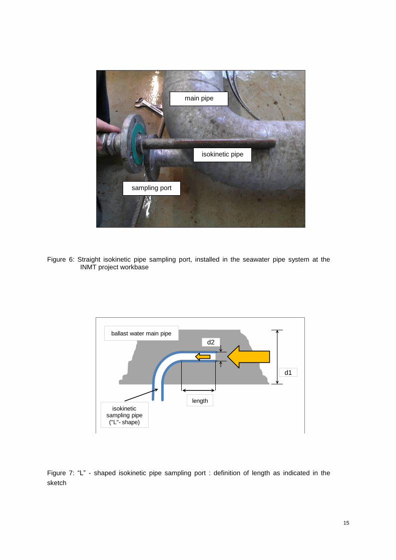
Figure 5: “L”-shaped, isokinetic sampling port, installed in the seawater pipe system at the INMT project workbase
Both sampling installations allowed the testing of different types of isokinetic pipes in
regard to diameter and length. For the definition of length cf. figures 7 and 8, page 15,
16.
For “L”-shaped isokinetic pipes length is defined as the distance from the entrance of
the isokinetic pipe until the the bow of the “L”-shaped pipe.
For straight isokinetic pipes length is the distance from the entrance of the isokinetic
pipe until the bow of the main ballast water pipe.
15
Figure 6: Straight isokinetic pipe sampling port, installed in the seawater pipe system at the INMT project workbase
Figure 7: “L” - shaped isokinetic pipe sampling port : definition of length as indicated in the
sketch
main pipe
isokinetic pipe
sampling port
ballast water main pipe
isokinetic sampling pipe ("L"- shape)
length
d1
d2

16
Figure 8: Straight isokinetic pipe sampling port : definition of length
Tested Isokinetic Pipes
Lengths : 0cm, 25cm, 50cm
Diameters : 1/2 inch, 1 inch, 2 inch
Table 2: Dimensions of isokinetic pipes tested at both types of sampling ports (cf. figure 9)
Figure 9: Different types of isokinetic pipes for sampling ports
ballast water main pipe
isokinetic sampling pipe length

17
10.1.1.2 Methodology
As described earlier any sampling port through which ballast water is sampled from a
main ballast water pipe onboard a ship should ensure that the sample taken represents
the conditions of the ballast water in the main ballast water pipe as much as possible.
Therefore any design of a sampling port should be tested as to the representativeness
of the samples taken. To assess this representativeness of the sampling port design it
is indispensible to define the total load of particles in the main ballast water pipe,
including the contained plankton organisms and determine this total load as 100%
(value I). Samples taken through the sampling port can be analyzed as to their total
load of particles, including plankton organisms (value II). The comparison of both
values, I and II, gives the percentage of sample representativeness.
To assess the representativeness of samples collected by the various combinations of
different isokinetic sampling pipes installed in the two types of sampling ports, a particle
count device was used: PAMAS S 4031.
The PAMAS S 4031 has an inbuilt optical sensor and volumetric cell design and allows
the counting of particles, including plankton organisms in a natural seawater or ballast
water sample, where the upper and lower detection size can be chosen at different
intervals within a rather wide range between 1µm and 400µm1.
The two major designs of sampling ports, “L”-shaped and “straight” (cf. para 10.1.1,
page 14) have been equipped with the different isokinetic pipes as displayed in table 2,
page 16.
For all tests, the detection range of particles including plankton organisms was set from
10µm to 100µm particles sizes in intervals of 10µm.
Furthermore, as described above the total particle content including plankton
organisms upstreams the installed sampling ports was determined to be 100%.
To sample the seawater upstream the respective sampling ports the entire pipe section
was closed by valves, the containing seawater was emptied from within the pipe
section into containers. Constantly stirred subsamples (volume 10ml) from this volume
were analyzed for the total particles within the size range of 10µm to 100µm. The
values of these counts were regarded as 100% particle load including plankton
organisms upstream the sampling ports.
Seawater samples taken through the respective sampling ports, too, were analyzed as
to the total numbers of particles including plankton organisms within the same size
range of 10µm to 100µm and the same interval of 10µm. Each of the described
sampling port combinations as well as the 100% determination were analyzed with
n=12 samples.
1 http://www.pamas.de/en/PARTICLE-COUNTERS/PORTABLE/PAMAS-S4031
/ http://www.pamas.de/de

18
To further diversify the 100% situation upstream the respective sampling ports the tests
were executed with samples of natural seawater from different seasons of the year
displaying different plankton densities.
10.1.1.3 Results
10.1.1.3.1 “L”-shaped isokinetic pipe sampling port
The results of the tests with different lengths and different diameters are displayed in
figure 10.
Figure 10: Results of tests with “L”-shaped isokinetic sampling port
The values scatter significantly from a representativeness of 85,8% (min) to 123,6%
(max) ( 37,8%) with a standard deviation from 4,15% (min) to 15,2% (max).
10.1.1.3.2 Straight isokinetic pipe sampling port
Figure 11: Results of tests with straight isokinetic sampling port
0,0
20,0
40,0
60,0
80,0
100,0
120,0
140,0
% of main flow
Representativeness of Sampling
straight isokinetic sampling pipe
0cm 25cm 50cm
0,5 inch0cm 25cm 50cm
1 inch0cm 25cm 50cm
2 inchLength
Diameter
0,0
20,0
40,0
60,0
80,0
100,0
120,0
140,0
% of main flow
Representativeness of Sampling
"L" shaped isokinetic sampling pipe
0cm 25cm 50cm0,5 inch
0cm 25cm 50cm1 inch
0cm 25cm 50cm
2 inchLength
Diameter

19
Less variable the values vary from a representativeness of 99,2% (min) to 113,5%
(max) ( 14,3%) with a standard deviation from 2,4% (min) to 13,5% (max).
10.1.1.4 Discussion of results and best combinations
The results clearly show that the “straight” design version of sampling ports yield a
much better representativeness for all tested isokinetic pipe variations (cf. figure 11,
see deviation values) than the “L”-shaped version.
During both tests values of more than 100% occur for both sampling port versions.
These exceeding values are due to partly hypo-kinetic situations directly at the
entrance of the isokinetic sampling pipe, generated by the differential pressure regime
of an open port and due to normal fluctuations in the capacity of the seawater pumps,
which maintain the volume flow through the main ballast water pipe.
As on the one hand the IMO regulations for the Ballast Water Management Convention
clearly demand an isokinetic sampling method with the installation of an “L”- shaped
isokinetic sampling pipe and on the other hand the installation of such an “L” - shaped
isokinetic sampling should be as easy and simple as possible for retrofit and new built
ships, isokinetic pipes with the same length, i.e. 0cm, and different diameter have been
compared.
With an isokinetic pipe of 0cm length and a diameter of 0,5 inch the confidentiality is
92,1% that the sample is representative.
The confidentiality values for the isokinetic pipes with a diameter of 1 inch, length 0cm
and 2 inch, length 0cm, are 94,3% and 93,9% respectively.
The mean confidentiality of the three isokinetic pipes defined above is 93,3%.
Port type Diameter of isokinetic
pipe (inch)
Length of isokinetic
pipe (cm) Confidentiality
“L”-shaped
0,5 inch 0 92,1%
1 inch 0 94,3%
2 inch 0 93,9%
Table 3: Confidentiality of the best combinations
Table 3 summarizes those combinations, which are in line with the recommendations
and regulations of the Ballast Water Management Convention at the same time
ensuring a very high representativeness of the samples taken.

20
10.1.2 ON BOARDSAMPLING SYSTEM: OPEN AND CLOSED SYSTEMS
A system installed for on board sampling of ballast water has to respect major criteria:
Adequate filtration
Variable sample volume
Minimal volumes of waste water
Easy, simple operation
Applicable to all ballast water pipe systems on all ships
In principle the on board sampling of ballast water followed by filtration via an isokinetic
sampling port can be executed with two alternative methods (cf. figure 13) :
(A) Open circuit sampling: after the filtration step the filtered ballast water is
directed into a recipient container or pumped over board
(B) Backflush sampling: after the filtration step the filtered ballast water is re-
directed into the on board ballast water pipe system
Figure 13: Alternatives for on board sampling; A: open circuit sampling, B: backflush sampling
The open circuit sampling demands additional technical installations representing a
major disadvantage, since the filtered ballast water has to be stored in recipient
containers or has to be pumped from the technical decks of a ship overboard by the aid
of additionally installed, adequate pumps.
In addition the installation of an open circuit sampling system creates a differential
pressure regime, where the pressure in the main ballast water pipe is reduced within
the open end isokinetic pipe. This differential pressure regime creates a hypo-kinetic
sampling system
ballast water main pipe
A
sampling system
ballast water main pipe
B

21
situation directly at the entrance of the isokinetic sampling pipe: the flow velocity in the
isokinetic sampling pipe increases.
The backflush sampling, in contrary, just needs a backflush port to be installed
downstream the sampling port, through which the filtered ballast water is re-directed to
the main ballast water pipe. The backflush sampling does not create a differential
pressure regime and meets all of the criteria listed above.
10.1.3 THE SGS MOBILE SAMPLING SYSTEM PROTOTYPE 01
10.1.3.1 Methodology
Based on the obtained results from the preceeding tests with different designs of
sampling ports and the determination of major criteria for the design of an on board
sampling system (cf. para 10.1.4), a mobile system for the sampling of ballast water on
board ships was designed and built (cf. figure 14 and 15, page 22).
From the isokinetic sampling port the ballast water enters a filter housing and runs
through a 36µm filter mesh (diagonale 50µm) to retain the IMO organism size class
>50µm. From the filter housing the ballast water passes along a straight section with an
inductive flowmeter, which records the volume filtered. Through an isokinetic sampling
bypass (straight isokinetic sampling pipe) additional samples are taken for the IMO
organism size classes >10µm<50µm and for the bacteria. The outflow is connected to
a backflush port installed downstream the isokinetic sampling port. Two pressure
gauges installed before and behind the filter housing allow for the monitoring of the
pressure regime within the filter housing to possibly indicate the clogging of the filter
mesh.
The Prototype 01 has a small footprint (40x60x90cm) and with a weight of less than 10
kg the system is easy to transport and the on board handling is simple. On board the
Prototype 01 is connected to the isokinetic sampling port and to the back flush port by
flexible, pressure resistant tubes. The major pipe elements of Prototype 01 have been
fixed to diameter of 2 inch, a dimension, which is regarded to be the upper limit for a
transportable system.
The functional scheme displayed in figure 14 has been transferred into the “SGS
Ballast Water Sampling System Prototype 01” shown in figure 15 (cf. page 22).

22
Figure 14: On board ballast water sampling system (scheme)
Figure 15: The SGS Ballast Water Sampling system Prototype 01
10.1.3.2 Dominant parameters and basic values for Prototype 01
The adequate filtration, i.e. the separation and concentration of the plankton organisms
from the ballast water is regarded as the pre-dominant criterion for a ballast water
sampling system, since it has by all means to be avoided that the live plankton
bypass sampling
isokinetic bypass
filterhousing
out
in
pressure gauge
pressure gauge
flow meter
valve

23
organisms in the ballast water are impacted by the filtration process itself.
Subsequently this criterion mainly addresses the flow velocity within the filter housing
of Prototype 01, which depends on (i) the diameter of the isokinetic pipe installed in the
sampling port and (ii) the flow velocity in the main ballast water pipe system of the ship.
The IMO regulations for the ballast water convention demand a maximum filtering
velocity of 0,5m/s, when samples are taken from within the ballast water tank by
plankton net samplers. This value was confirmed by various national and international
institutions for marine research. The differential pressure from both sides, inside and
outside the filter material, too, can be taken as an indicator for the adequate separation
of plankton organisms. Experimental tests with plankton nets show that a differential
pressure of >0,2 bar disintegrates the plankton organisms.
10.1.3.3 Hydraulic tests with Prototype 01
For the hydraulic tests Prototype 01 was connected to a straight isokinetic pipe
sampling port of the main ballast water treatment system at the INMT. For these tests
with Prototype 01 the ballast water filter of the INMT ballast water treatment system
was switched on.
Figure 16: Straight isokinetic pipe sampling port in the ballast water treatment system of the INMT
The tests were executed in a quite broad range of values for the basic parameters such
as volume flow, pressure and pipe diameter (cf. table 4 and 5, page 24).

24
Volume Flow
(m³/h)
Pressure
(bar)
30 0,2
80 < 0,2
80 0,8 – 0,9
80 1,6 – 1,8, max 3,2
160 1,0 , max 2,6
198 1,1 – 1,2
Table 4: Basic parameters for hydraulic tests with Prototype 01, volume flow and pressure
Pipe Inner Diameter
(mm)
BW system at INMT 100,0
Isokinetic pipe in sampling port 25,4
Tube connecting Prototype 01 with isokinetic sampling port 52,6
Inlet at filterhousing 50,8
Filterhousing 123,7
Table 5: Basic parameters for hydraulic tests with Prototype 01, diameter of pipes
After crushing tests under various conditions further hydraulic tests with Prototype 01
were executed (i) as an open circuit sampling system and (ii) as a backflush sampling
system (cf. figure 13, page 20). The volume flow and the flow velocities were recorded
from volume meters and flow meters installed in the different pipe sections of the
prototype.
10.1.3.4 Filtrations tests with Prototype 01
The filtration tests with Prototype 01 were executed under the hydraulic conditions
described in para 10.1.5.3 (cf. page 23) using two different types of filter displayed in
figure 17 and 18, page 25.
The filter shown in figure 17 represents a technical filter used in the beverage
industries. The filter presented in figure 18 was designed and constructed especially for
the filter housing within the frame of this project. During filtration the plankton
organisms are collected in the small beaker at the lower end of the filter. The beaker
can easily be screwed off for the recovery of the trapped plankton organisms.
25
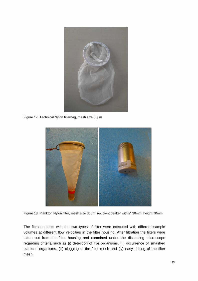
Figure 17: Technical Nylon filterbag, mesh size 36µm
Figure 18: Plankton Nylon filter, mesh size 36µm, recipient beaker with 30mm, height 70mm
The filtration tests with the two types of filter were executed with different sample
volumes at different flow velocities in the filter housing. After filtration the filters were
taken out from the filter housing and examined under the dissecting microscope
regarding criteria such as (i) detection of live organisms, (ii) occurrence of smashed
plankton organisms, (iii) clogging of the filter mesh and (iv) easy rinsing of the filter
mesh.
26
10.1.4 MOBILE SAMPLING SYSTEM PROTOTYPE 01: RESULTS
10.1.4.1 Hydraulic tests
The crushing tests with the Prototype 01 revealed that the sampling system is
compression-proof to system pressures of >3,2 bar.
The results for the flow velocity measurements from both test cycles, (i) open circuit
sampling system and (ii) backflush sampling system (cf. figure 13, page 20) were cross
checked with the results of the relevant mathematical calculations based on the
parameters ‘volume flow’ and ‘pipe diameter’ in the different sections.
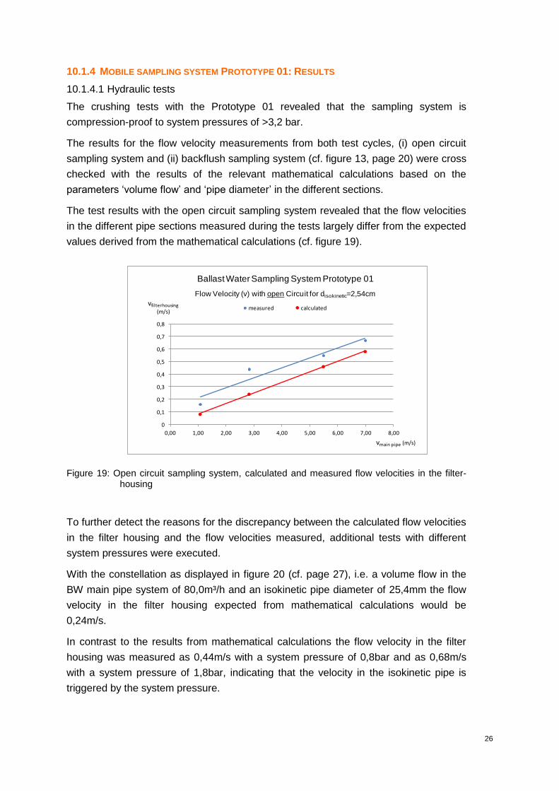
The test results with the open circuit sampling system revealed that the flow velocities
in the different pipe sections measured during the tests largely differ from the expected
values derived from the mathematical calculations (cf. figure 19).
Figure 19: Open circuit sampling system, calculated and measured flow velocities in the filter-housing
To further detect the reasons for the discrepancy between the calculated flow velocities
in the filter housing and the flow velocities measured, additional tests with different
system pressures were executed.
With the constellation as displayed in figure 20 (cf. page 27), i.e. a volume flow in the
BW main pipe system of 80,0m³/h and an isokinetic pipe diameter of 25,4mm the flow
velocity in the filter housing expected from mathematical calculations would be
0,24m/s.
In contrast to the results from mathematical calculations the flow velocity in the filter
housing was measured as 0,44m/s with a system pressure of 0,8bar and as 0,68m/s
with a system pressure of 1,8bar, indicating that the velocity in the isokinetic pipe is
triggered by the system pressure.
0
0,1
0,2
0,3
0,4
0,5
0,6
0,7
0,8
0,00 1,00 2,00 3,00 4,00 5,00 6,00 7,00 8,00
measured calculatedvfilterhousing
(m/s)
BallastWater Sampling System Prototype 01
Flow Velocity (v) with open Circuit for disokinetic=2,54cm
vmain pipe (m/s)

27
Figure 20: Open circuit sampling system, calculated and measured flow velocities in the filter-housing under different system pressures
The test results with the backflush sampling system revealed that the flow velocities in
the different pipe sections measured during the tests do not differ from the expected
values derived from the mathematical calculations (cf. figure 21).
Figure 21: Backflush sampling system, expected and measured flow velocities in the filter-housing
0
0,2
0,4
0,6
0,8
1
Diagrammtitel
vfilterhousing (m/s)
BallastWater Sampling System Prototype 01
Flow velocity (v) with open circuit for disokinetic= 2,54cm and Qmain pipe= 80,0 m³/h
calculatedP = 0,8 bar P = 1,8 bar
measured at system pressure
0,00
0,10
0,20
0,30
0,40
0,50
0,60
0,70
0,00 1,00 2,00 3,00 4,00 5,00 6,00 7,00 8,00
measured calculatedvfilterhousing
(m/s)
Ballast Water Sampling System Prototype 01
Flow Velocity (v) with Backflush for disokinetic=2,54cm
vmain pipe (m/s)

28
10.1.4.2 Filtration tests
The filtration tests executed with two different types of filters as displayed in figures 17
and 18 (cf. page 25) revealed similar results. With flow velocities in the filter housing
exceeding 0,5m/s the live plankton organisms in the ballast water are killed during
filtration.
Figure 22 displays the technical filter after sampling a ballast water volume of 6m³ at a
flow velocity in the filter housing of 1,3m/s.
Figure 22: Technical Nylon filter after sampling
Figure 23 displays the technical filter after sampling a ballast water volume of 1m³ at a
flow velocity in the filter housing of 0,6m/s.
Figure 23: Technical Nylon filter after sampling
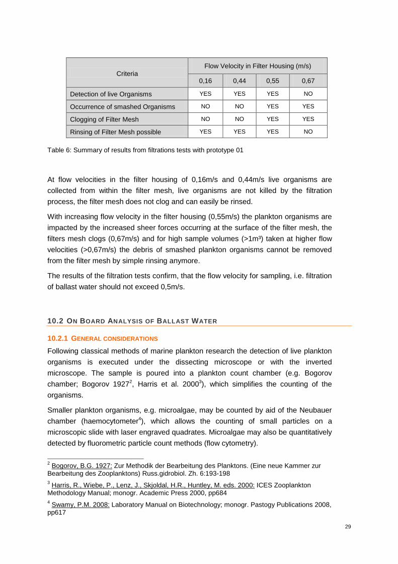
The results from the filtrations tests are summarized in table 6.
29
Criteria Flow Velocity in Filter Housing (m/s)
0,16 0,44 0,55 0,67
Detection of live Organisms YES YES YES NO
Occurrence of smashed Organisms NO NO YES YES
Clogging of Filter Mesh NO NO YES YES
Rinsing of Filter Mesh possible YES YES YES NO
Table 6: Summary of results from filtrations tests with prototype 01
At flow velocities in the filter housing of 0,16m/s and 0,44m/s live organisms are
collected from within the filter mesh, live organisms are not killed by the filtration
process, the filter mesh does not clog and can easily be rinsed.
With increasing flow velocity in the filter housing (0,55m/s) the plankton organisms are
impacted by the increased sheer forces occurring at the surface of the filter mesh, the
filters mesh clogs (0,67m/s) and for high sample volumes (>1m³) taken at higher flow
velocities (>0,67m/s) the debris of smashed plankton organisms cannot be removed
from the filter mesh by simple rinsing anymore.
The results of the filtration tests confirm, that the flow velocity for sampling, i.e. filtration
of ballast water should not exceed 0,5m/s.
10.2 ON BOARD ANALYSIS OF BALLAST WATER
10.2.1 GENERAL CONSIDERATIONS
Following classical methods of marine plankton research the detection of live plankton
organisms is executed under the dissecting microscope or with the inverted
microscope. The sample is poured into a plankton count chamber (e.g. Bogorov
chamber; Bogorov 19272, Harris et al. 20003), which simplifies the counting of the
organisms.
Smaller plankton organisms, e.g. microalgae, may be counted by aid of the Neubauer
chamber (haemocytometer4), which allows the counting of small particles on a
microscopic slide with laser engraved quadrates. Microalgae may also be quantitatively
detected by fluorometric particle count methods (flow cytometry).
2 Bogorov, B.G. 1927: Zur Methodik der Bearbeitung des Planktons. (Eine neue Kammer zur
Bearbeitung des Zooplanktons) Russ.gidrobiol. Zh. 6:193-198
3 Harris, R., Wiebe, P., Lenz, J., Skjoldal, H.R., Huntley, M. eds. 2000: ICES Zooplankton
Methodology Manual; monogr. Academic Press 2000, pp684
4 Swamy, P.M. 2008: Laboratory Manual on Biotechnology; monogr. Pastogy Publications 2008,
pp617
30
The concentration of marine bacteria in the seawater is assessed by cultivation
methods on group or species specific agars and 24/48 hour incubation.
All of these methods are either very time consuming (plankton counts, incubation of
bacteria), their accuracy depend on the skill of the executing person (plankton counts)
or demand bulk material (particle count methods).
The economic efficiency of international ship traffic mainly depends on smooth,
timesaving operations, both on the open sea and in the harbors. Any delay has to be
avoided, since it subsequently ends in an unacceptable economic loss for the ship
owner.
In this regard the assessment of the compliance of an on board ballast water treatment
system within the regulations of the Ballast Water Management Convention should
respect the economic time frame under which the ships have to operate.
As a consequence the on board compliance testing should make use of methods that
enable the executing person to generate reliable data under a set of arduous
conditions on board a ship under operation or in the harbor:
Technical decks on ships do not leave much space for analytical apparatus and material.
Special on board safety regulations have to be respected.
Sampling has to respect on board operations for de-ballasting.
Restricted time availability for the execution of sampling and analytical procedures.
Analytical data have to be generated as rapid as possible to enable port state controls to clearly define adequate consequences in case of non-compliance.
Under these pre-conditions the traditional methods to analyze ballast water for the
content of viable plankton organisms are by no means applicable for the on board
compliance testing.
However, the need to respect the time constraints and at the same time generate
reliable results requires a complex solution.
(1) The on board analysis of ballast water should be of indicative
character.
(2) Compliance or non-compliance should be indicated by a value
of “gross exceedance” in respect to the standards for each of
the three organism classes set-up by the IMO (cf. table 1, page
9).
(3) Orientated along (1) and (2) new analytical methods, applicable
for ballast water analysis on board ships under operation, are

31
needed to accurately and rapidly generate data to indicatively
assess the “gross exceedance” of the IMO standards.
(4) The further development of already available, rapid analytical
methods for the detection of chemical substances may result in
the convertion of concentration values into numerical values.
10.2.2 FLUORESCEIN-DIACETATE FLUOROMETRY – FDA
(paragraph provided by Prof. Dr. Nick Welschmeyer, abbr.)
The FDA method is a fluorometric assay whose analytical signal responds positively
and quantitatively to total living biomass - in any planktonic organism; bacteria, protist,
or metazoan. FDA is a non-fluorescent compound which, when hydrolyzed by
biological enzyme activity, yields fluorescein, a highly fluorescent compound that
clearly marks ‘live’ cells with optically-induced green fluorescent emission. Killed cells
yield no fluorescent product. FDA has been utilized as a cell-specific tag for cellular
viability for almost five decades and is now the recommended procedure in US
EPA/ETV ballast water testing protocol for plankton organisms of 10-50 μm in size.
However, the execution of the method, through its history to the present, is based on
numeric microscope counts, requiring tedious observation, expert technicians and
bulky instrumentation – it is not a candidate for ‘rapid’ compliance testing.
The method has been converted into a bulk, cuvet-based technique that requires a
single measurement on a hand-held, battery-operated fluorometer. The proprietary
reagent promoting the quantitative reaction was designed specifically to operate with all
freshwater and marine organisms from the full range of anticipated ballast salinities (0-
35 PSU). The properties of the viability reaction in the new method are now well
documented:
The fluorescent response scales directly with biomass
analyzed (volume filtered)
The fluorescent response scales directly with incubation time
over the range 15 min – 4 h.
The fluorescent response scales quantitatively with
temperature, having a Q10 of 2 (e.g., incubation at 20 °C
yields twice the fluorescence of incubation at 10 °C)
The technique has been targeted specifically to the analysis of the problematic 10-50
μm IMO organism size class. A glass of ballast water (100–200 ml) provides enough
sample material for rapid test completion in less than one hour. The aim was to devise
a relatively fool-proof method that can be executed reliably in the field with minimum
technical training and no lab facilities, yet still provide the sensitivity to detect
undesirable living planktonic biomass in ballast water at low viable concentrations
commensurate with ballast water performance standards. In collaboration with other
companies beta test kits were assembled and distributed for peer review to different
user groups, which resulted in the modification of the protocol and kit-content so that it
32
is a syringe-based, pipet-free operation with encapsulated filters that remove any risk
of contamination onboard ship.
The bulk FDA method has now been calibrated for organism response, linked to
traceable standards, allowing simple conversion of wet-chemical fluorescein detection
to be converted to equivalent numeric viable counts within the 10-50 μm IMO organism
size class.
10.2.3 PULSE AMPLITUDE MODULATION FLUOROMETRY – PAM
(paragraph provided by Prof.Dr. Nick Welschmeyer, abbr.)
This method is based on the well-known measurement of phytoplankton variable
fluorescence (sometimes referred to as ‘active’ fluorescence, pulse amplitude
modulated (PAM) fluorescence, fast repetition rate (FRR) fluorescence, etc.). The
technique provides a non-invasive, optical method of determining the maximum
quantum efficiency of dark-adapted algae (moles of potential carbon fixation per mole
of absorbed photons). The most common product of the analysis is a dimensionless
fluorescence ratio, Fv/Fm, computed from minimum, Fo, and maximum, Fm, levels of
chlorophyll fluorescence measured under states of active an inactive photosynthetic
centers within the algal cell. Specifically, natural, healthy phytoplankton are expected to
exhibit a dark adapted Fv/Fm of ca. 0.7 and dead phytoplankton yield dark adapted
Fv/Fm of zero; the ‘live’ and ‘dead’ status of the phytoplankton lies within these
reproducible limits (0 – 0.7)
The actual measurement is extremely fast (<2 sec), extremely simple (single push-
button) and the results have direct bearing on the evaluation of ballast treatment
efficacy.
Generally, the technology has been considered quite complementary to the suite of all
viability measurements made during ballast treatment testing. In response to the need
for simple, rapid compliance measurements, the method has been modified to provide
unambiguous single-step operation to yield the parameters useful to compliance
testing. The technique requires no sample blanking or sensitivity adjustments and no
wet reagents. It meets the requirement of a ‘fast, indicative’ and is limited only in this
regard: 1) it responds only to chlorophyll-containing microalgae 2) the ratio Fv/Fm is
concentration-independent and therefore bears no relation to numeric abundances of
living organisms; 3) parameter Fv has the potential to relate semi-quantitatively to
numeric living phytoplankton cells, however, the wide variation in cellular chlorophyll
content (ten-fold) for any given algal species suggests this concentration-dependent
parameter will be subject to greater variability in its theoretical relation to numeric
viable counts than the enzyme-based bulk FDA method described above.
10.2.4 ADENOSIN-TRIPHOSPHATE FLUOROMETRY - ATP
Adenosine Triphosphate - ATP, is a substance of central importance for the
physiological processes in any living cell. Within the cell compartments the ATP

33
molecule is charged with chemical energy, which is passed on to other intracellular
carrier molecules then.
Within a water sample containing microorganisms, there are two types of ATP (i) intra-
cellular ATP - ATP contained within living biological cells and (ii) extra-cellular ATP -
ATP contained outside of living biological cells.
Thus the total concentration of ATP (tATP) in a water sample comprises intra-cellular
ATP (cATP) and extra cellular or dissolved ATP (dATP).
tATP = cATP + dATP E2
Accurate measurement of these types of ATP is critical in the application of ATP-based
measurements especially for assessments of concentration of the living biomass in a
sample.
ATP is an important co-factor for the Luciferin-Luciferase reaction, in which Luciferin
(LH) is transferred by Luciferase in presence of oxygen and ATP:
E3
Luciferin gets fluorescent and emits light at max= 537nm with the amount of light (h)
being direct proportional to the amount of ATP molecules. The fluorescence is
measured as relative light units (RLU) by fluorometry (luminometer).
The assessment of viable biomass in a water sample through the concentration of
cATP in the sample is a common method in a wide range of applications since years :
potable water, sanitary water, cooling water, industrial process water, waste water,
petrol and bio-fuel.
The Luminultra Quench Gone Aqueous QGATM distributed by Aqua Tools is a highly
sensitive test kit for the detection of bacteria in liquid samples. The second generation
of this kit line reflects the overlapping of cATP and tATP and physically separates the
dATP from the tATP (cf. E2) and thus clearly addresses the cATP in the sample.
In cooperation with Luminultra, Canada and Aqua Tools, France, the QGATM test kit
line was taken as a base for the further development of a protocol for ballast water
analysis.
Initial test series with marine microalgae revealed that the extraction technique to
mobilize the ATP from within the cells is crucial for accurate analysis of cATP in ballast
water samples.
Various extraction tests have been performed with cultured microalgae, with cultured
Artemia salina individuals as well as with natural plankton samples from the Baltic Sea
and the North Sea.
LH2 + O2 + ATP Luciferase
Mg 2+oxy-L + CO2 + AMP + h

34
The final protocol uses the technique of grinding with beating beads to extract the ATP
from the plankton organisms followed by the QGATM protocol. The time needed from
sample to result is 6-8 minutes. The evaluation of this method regarding the correlation
between the concentration of cATP in a ballast water sample and the density of viable
organisms in the sample was performed with seawater samples from the Baltic Sea
and the North Sea with a known organism density. The results of this evaluation are
displayed in figures 24, and 25, page 34.
Figure 24: Correlation between cATP concentration and number of organisms >50µm in ballast water
In its final stage of development the Luminultra ballast water test kit line will encompass
the analysis of all of the three IMO organism size classes, organisms >50µm,
organisms >10µm<50µm and bacteria.The ATP method for ballast water analysis still
has to pass a validation phase executed by an independent institute.
Figure 25: Correlation between cATP concentration and number of organisms >10µm<50µm in ballast water
y = 0,1273xR² = 0,9931
0
5
10
15
20
25
30
35
0 50 100 150 200 250
cATP in marine Plankton Organisms >50µmcATP (ng/ml)
number of organisms
y = 0,0922xR² = 0,9961
0
5
10
15
20
25
30
35
0 50 100 150 200 250
cATP in marine plankton organisms >10µm<50µmcATP (ng/ml)
number of organisms
35
10.2.5 FLUORESCENCE-IN-SITU HYBRIDIZATION - FISH
Fluorescence in situ hybridization – FISH is a technique in cytogenetic, used to detect
and localize the presence or absence of specific DNA sequences. FISH uses
fluorescent gene probes binding to only those parts of the chromosome with which they
show a high degree of sequence complementarity. By means of fluorescence
microscopy the fluorescent probe can be detected and its location where it is bound to
the chromosomes. FISH is applied to assess specific features in DNA in the field of
genetic counseling, medicine, and species identification.
The ScanVIT Ecoli/Coliforms test kit produced by vermicon, Munich, Germany,
represents the fastest FISH test kit yielding real quantitative data of the concentration
of viable bacteria in fresh water samples within a time frame of 8 hours. The ScanVIT
Ecoli/Coliforms test kit formed the basis for the further development of a rapid FISH
test kit for the qualitative and quantitative detection of the three bacteria groups in
ballast water samples defined by the IMO as target organisms within the frame of the
Ballast Water Management Convention. The aim of the further development of the
ScanVIT Ecoli/Coliforms test kit was to combine the qualitative and quantitative
detection of all of the three bacterial target groups possibly in just one assay with a
minimum of time requirements.
Specific gene probes were designed in silico for the detection of Enterococcus spp.
and for Vibrio cholerae. The gene probes are specifically designed for the detection of
viable bacteria of Enterococcus spp. and for Vibrio cholerae in ballast water samples.
Both gene probes were tested in silico and in situ on target and non target strains and
results confirmed the specificity on the probes: only target bacteria were detected with
the probes whereas non-target cells could be discriminated, giving negative results with
the probes.
The developed protocols were tested on spiked and non-spiked sea water samples and
confirmed that the ScanVIT approach is applicable for seawater samples, too. No
negative impact on the performance of the test was observed and the target bacteria
could successfully be quantified within a time span of 10 to 12 hours.
At present the ScanVIT test kit for ballast water is in its final stage of development. An
internal evaluation will be executed by the end of June followed by the delivery of the
first beta test kits in the months of July and August 2013.
10.2.6 ANALYTICAL METHODS FOR RAPID ON BOARD COMPLIANCE TESTING : SAFETY ISSUES
As the methods FDA, ATP and FISH make use of chemicals, the availability of Material
Data Safety Sheets – MSDS for the relevant chemicals is obligatory within the frame of

36
the Globally Harmonized system of Classification, Labelling and Packaging of
Chemicals – GHS.
The MSDS for ATP and FISH have been finalized and are ready for publication. The
elaboration of the MSDS for FDA will be finished by the time of the final report of this
project.
Since the PAM method does not use any chemical, no MSDS has to be elaborated for
this method.
10.2.7 ANALYTICAL METHODS FOR RAPID ON BOARD COMPLIANCE TESTING
The following table lists the different analytical methods, their application range and the
time needed from sample to result.
Method IMO organism size class Time to result
FDA >10µm<50µm 1 hour
PAM >50µm, >10µm<50µm
(only for phytoplankton) 2 minutes
ATP all classes 6-8 minutes
FISH bacteria 10-12 hours
Table 7: Analytical methods for rapid, indicative, on board ballast water compliance tests
11 COMMENTS
11.1 APPLICATION RANGE OF THE SAMPLING SYSTEM PROTOTYPE 01
The limit flow velocity of approximately 0,5 m/s for the safe filtration of plankton
organisms from ballast water and the dimensioning of the major pipe diameter in the
sampling system Prototype 01 to maximal 2 inch subsequently presets the maximum
diameter of the isokinetic pipe in the sampling port, which in fact triggers the time
needed to take a ballast water sample with a pre-defined volume as well.
To better describe the relation between diameter of isokinetic pipe, flow velocity in the
main ballast water pipe and the time needed for sampling two arbitrarily chosen
examples are given in table 8 below, page 37.
For ship A the resulting flow velocity in the filter housing is 4,24m/s which results in a
very acceptable time for sampling of just 1,4 min. However, the maximum flow velocity
for the safe filtration of the plankton organisms is exceeded by far.
For ship B the resulting flow velocity in the filter housing is just 0,05m/s, which does not
impact the plankton organisms during the filtration process at all. However, the time for
37
sampling is prolonged to 2 hours 45 minutes, which is completely unacceptable seen to
the time constraints there are for on board sampling and analysis.
It is very essential to assess the application range of the sampling system Prototype 01
in the context of on board sampling and in the view of the parameters adequate flow
velocity for filtration and minimum possible time for sampling.
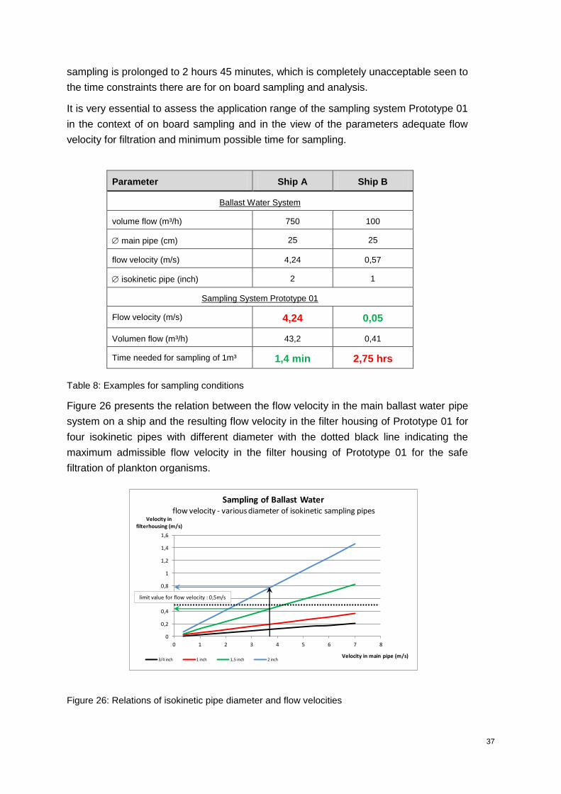
Parameter Ship A Ship B
Ballast Water System
volume flow (m³/h) 750 100
main pipe (cm) 25 25
flow velocity (m/s) 4,24 0,57
isokinetic pipe (inch) 2 1
Sampling System Prototype 01
Flow velocity (m/s) 4,24 0,05
Volumen flow (m³/h) 43,2 0,41
Time needed for sampling of 1m³ 1,4 min 2,75 hrs
Table 8: Examples for sampling conditions
Figure 26 presents the relation between the flow velocity in the main ballast water pipe
system on a ship and the resulting flow velocity in the filter housing of Prototype 01 for
four isokinetic pipes with different diameter with the dotted black line indicating the
maximum admissible flow velocity in the filter housing of Prototype 01 for the safe
filtration of plankton organisms.
Figure 26: Relations of isokinetic pipe diameter and flow velocities
0
0,2
0,4
0,6
0,8
1
1,2
1,4
1,6
0 1 2 3 4 5 6 7 8
Velocity in filterhousing (m/s)
Velocity in main pipe (m/s)
Sampling of Ballast Waterflow velocity - various diameter of isokinetic sampling pipes
3/4 inch 1 inch 1,5 inch 2 inch
limit value for flow velocity : 0,5m/s

38
As an example the black vertical arrow indicates a flow velocity of 3,75 m/s in the main
BW pipe system on a ship. In case the sampling port provides an isokinetic pipe with a
diameter of 2 inch, this would result in flow velocity in the filter housing of
approximately 0,78m/s (blue horizontal arrow), which exceeds the admissible flow
velocity of 0,5m/s.
However, if the sampling port provides an isokinetic pipe with a diameter of 1 inch, the
resulting flow velocity in the filter housing drops beyond the limit value to just 0,43m/s
(green horizontal arrow).
As a conclusion the use of isokinetic pipes with diameter of 1inch will
make the sampling system Prototype 01 applicable for all BW pipe
systems on all ships.
Following this conclusion a universal sampling port has been designed and
constructed, which allows for the use of isokinetic pipes with three different diameters,
1 inch, ½ inch and ¾ inch. This universal sampling port is actually under construction.
However, it has to be clearly underlined that taking several samples of adequate large
volume, as required by the IMO, subsequently prolongs the overall time for an
indicative compliance analysis to a large extent disregarding any optimization of the
technical sampling arrangements.
11.2 THE ISOKINETIC PRINCIPLE
The relevant protocols of the USCG as well as the IMO demand an isokinetic sampling
port. Although quite a number of publications clearly describe the straight isokinetic
pipe sampling port and the “L” shaped isokinetic pipe sampling port to be the preferable
designs for an isokinetic sampling port, the results presented in para 10.1.6.1, page 26,
clearly depict, that an open circuit sampling of ballast water via an isokinetic sampling
port generates a much higher flow velocity in the sampling port pipe than in the BW
main pipe (cf. figure 19, page 26).
Some of the publications did not consider the system pressure in the ballast water main
pipe, to which the sampling system is flanged.
Ballast water pipe systems are operated with a system pressure of up to 3 bar. The
opening of the ball valve at the isokinetic sampling port, which has to be fully opened to
ensure isokinetic flow, immediately creates a differential pressure between the ballast
water main pipe and the isokinetic pipe triggering an increase of the flow velocity in the
isokinetic pipe by creating a hyperkinetic situation at the opening of the isokinetic pipe
facing upstream in center of the ballast water main pipe.
39
Thus the sampling of ballast water through an isokinetic pipe with an open circuit
system can never be “isokinetic”.
The closed backflush sampling system, in contrast, does not generate a
differential pressure and the sampling of ballast water through such a
system is “truly isokinetic” in its original sense.
12 CONTINUATION OF PROJECT ACTIVITIES
Following the manifold results from the numerous test series conducted within the
frame of this research and development project so far, the further project activities will
now concentrate on these aspects:
Construction and testing of an universal isokinetic sampling port
Further testing and validation of the mobile sampling system and all analytical
methods
Tests of the sampling system and the analytical methods on a ship in operation,
i.e. under real conditions
Execution of various other, additional project activities
12.1 ISOKINETIC SAMPLING PORTS
(1) To further simplify the use of the sampling system Prototype 01 on board
ships a universal isokinetic sampling port has been developed. It allows for
the rapid and variable installation of three isokinetic sampling pipes with
different diameter and independent from the diameter of the main ballast
water pipes, the universal isokinetic sampling port fits all flange sizes and
already entered the production cycle.
12.2 SGS BALLAST WATER SAMPLING SYSTEM PROTOTYPE 01
(2) Additional tests will be performed with sampling system Prototype 01 to
assess the performance of a new filter material. The filter is produced by
Actionlaser, an Australian company, which produces laser perforated
stainless steel filter material.

40
Figure 27: Stainless steel filtermaterial, left: tube filter, right close-up of perforation (Actionlaser, Australia)
Actionlaser will provide a perforated, stainless steel filter material with hole
size of 50µm.
(3) A final validation of the SGS ballast water sampling system Prototype 01 will
be executed by an independent institution.
(4) The sampling system Prototype 01 will be tested on board a ship under
operation.
12.3 ANALYTICAL METHODS
(1) The FISH method will be validated by an independent institution.
(2) The ATP method will be validated by an independent institution.
12.4 OTHERS
(1) Elaboration of SOPs for the new methods
(2) Elaboration of training material
(3) Execution of a training seminar for on board ballast water compliance testing
(4) Elaboration of final project report
(5) A peer review publication
(6) Maintenance of a project website

41
13 ANNEX
13.1 PROJECT CO-OPERATION PARTNERS
Co-operation Partner Field of Expertise
Moss Landings Marine
Laboratories, USAOfficial project partner
Institute for Nautics and Maritime
Technologies, GermanyProject workbase, provision of workshop, BW laboratory and personnel
BlueBioTech, Germany Provision of live marine microalgae, laboratory workspace and personnel
Microbi Maris Biotech, Germany Marine microbiological services
ANKON, Germany Steel construction works at project workbase
Hydro Bios, Germany Production of marine scientific apparatus
Institute for Marine Science-
GEOMAR, GermanyExchange of information on marine planktonology
Institute for Hydrobiology and
Fisheries Science, GermanyExchange of information on marine planktonology
Bollfilter Protectionsystems,
GermanyProduction of ballast water filters
Vermicon, Germany Development of FISH microscopy for on board analysis
AQUA TOOLS, France Production of ATP test kits
Luminultra, Canada Production of ATP test kits
Royal Netherlands Institute for
Sea Research, NetherlandsConsultations on BW sampling and analysis
Marine Eco Analytics, Netherlands Consultations on BW sampling and analysis
Norwegian Institute for water
research, NorwayConsultations on BW sampling and analysis, validation services
42
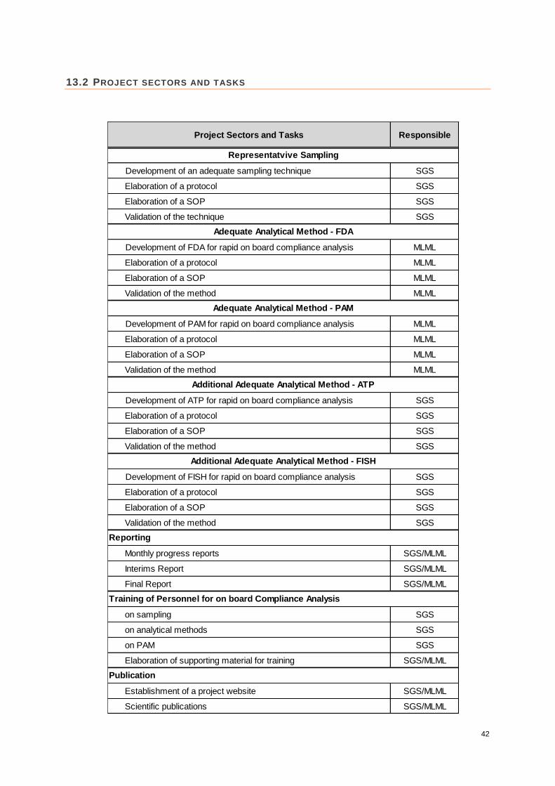
13.2 PROJECT SECTORS AND TASKS
Project Sectors and Tasks Responsible
Development of an adequate sampling technique SGS
Elaboration of a protocol SGS
Elaboration of a SOP SGS
Validation of the technique SGS
Development of FDA for rapid on board compliance analysis MLML
Elaboration of a protocol MLML
Elaboration of a SOP MLML
Validation of the method MLML
Development of PAM for rapid on board compliance analysis MLML
Elaboration of a protocol MLML
Elaboration of a SOP MLML
Validation of the method MLML
Development of ATP for rapid on board compliance analysis SGS
Elaboration of a protocol SGS
Elaboration of a SOP SGS
Validation of the method SGS
Development of FISH for rapid on board compliance analysis SGS
Elaboration of a protocol SGS
Elaboration of a SOP SGS
Validation of the method SGS
Monthly progress reports SGS/MLML
Interims Report SGS/MLML
Final Report SGS/MLML
on sampling SGS
on analytical methods SGS
on PAM SGS
Elaboration of supporting material for training SGS/MLML
Establishment of a project website SGS/MLML
Scientific publications SGS/MLML
Publication
Additional Adequate Analytical Method - ATP
Additional Adequate Analytical Method - FISH
Representatvive Sampling
Adequate Analytical Method - FDA
Adequate Analytical Method - PAM
Reporting
Training of Personnel for on board Compliance Analysis
43
Taunusstein, November, 22nd, 2013
…………………………………………………………
Dr. Lothar Schillak (SGS Institut Fresenius GmbH, Taunusstein, Germany)
…………………………………………………………
Peter-Paul Stehouwer (SGS Germany GmbH, Hamburg, Germany)