Embed Size (px)
Citation preview
A reliable distributed cellular core networkfor hyper-scale public clouds
Binh Nguyen?, Tian Zhang?, Bozidar Radunovic‡, Ryan Stutsman?
Thomas Karagiannis‡, Jakub Kocur†, Jacobus Van der Merwe?
?University of Utah, ‡Microsoft Research, †Core Network Dynamics
Microsoft research technical report MSR-TR-2018-4
ABSTRACTEconomies of scale associated with hyper-scale public cloudplatforms offer flexibility and cost-effectiveness, resulting invarious services and businesses moving to the cloud. Onearea with little progress in this direction is cellular core net-works. A cellular core network manages the state of cellularclients; it is essentially a large distributed state machine withvery different virtualization challenges compared to typicalcloud services. In this paper we present a novel cellular corenetwork architecture, called ECHO1, particularly suited topublic cloud deployments, where the availability guaranteesmight be an order of magnitude worse compared to existing(redundant) hardware platforms. We present the design andimplementation of our approach and evaluate its functionalityon a public cloud platform. Analysis shows ECHO promiseshigher availability than existing telco solutions.
1. INTRODUCTIONRecent years have seen a tremendous uptake of cloud com-
puting. More and more companies move their services tothe public cloud to take advantage of the economies of scale,the resource elasticity and scalability that the cloud offers.In stark contrast, the telco industry today faces major chal-lenges in equipment upgrading, scaling, and introducing newservices [21]. Cellular core networks are largely still basedon custom-built hardware mandated by the strict reliabilityrequirements posed by running a mobile core network [55,61].
To alleviate these challenges, telcos and cellular operatorsare attempting to virtualize their core networks through net-work function virtualization (NFV) [10]. Typically, this is inthe form of a move to a private-cloud setting, where the telcoprovider has full control of the infrastructure and can optimizethe whole stack for its particular services. Indeed, owningthe whole cloud stack can allow for the addition of special-ized functionality for fault tolerance and management [48,49, 62]. However, this functionality typically imposes extra
1After “Echo, the Nymph of Steady Reply” from Greek mythology.
constraints on cloud design (e.g. imposes locality, low-levelnetwork access). A super-optimized cloud stacks for a par-ticular core service might not be able to scale to the size ofa public cloud, and may be at odds with the requirements ofa new service to be introduced. Telco providers will have tomanage and maintain the new private cloud deployments andwill not be able to take full advantage of the economies ofscale a public hyper-scale cloud deployment can offer.
Instead, the question we address is whether it is feasibleto implement a cellular core network on top of a hyper-scalepublic cloud, such as Amazon AWS or Microsoft Azure. Toachieve this, one has to address three main challenges. First,reliability - a typical public cloud availability SLAs are “four9s” (i.e., availability of 99.99%) or less, but only if a service isdeployed across several VMs in different availability sets [44,7]. In contrast, a cellular core network today often requiresup to five 9s reliability [19, 47], and comprises differentmonolithic components. Such a reliability requires replicationof components across VMs and across multiple data centres.Secondly, failover architectures in hyper-scale clouds are verydifferent from private data centers because of their scales. Atypical fault detection in a public cloud is of order of 10seconds [8, 45], in order to limit false positives [27]. This istoo slow for a cellular core whose timeouts are of order of 1second, hence we cannot apply the same fail-over techniquesfrom private telco clouds. Finally, a cellular core requiresconsistency of mobile clients’ session state across multiplenetwork components and end-user devices. This makes itfundamentally different than virtualizing middle-boxes [24,58, 23, 56] and other web services.
In this paper, we redesign the EPC architecture for a hyper-scale public cloud deployment with three goals in mind. First,it should take into account the unpredictability of the publiccloud. Second, it should be backward compatible with theexisting hardware and network deployments (phones and basestation). Third, allow only for minimum modification to theexisting EPC design and avoid any new dependencies on thespecifics of cellular signalling protocols which can and willchange in time.
1
To this end we introduce ECHO, a distributed network ar-chitecture for the evolved packet core (EPC) on the publiccloud. We focus on the control plane of the evolved packetcore (EPC) [1], which manages session states. All ECHOcomponents are distributed across multiple VMs as no sin-gle VM can provide sufficient reliability. Fundamentally,ECHO must be redundant across VMs without relying onthe availability of any particular VM or the paths to it. Atthe same time, using multiple VMs introduces consistencyissues, which we found can also led to customer-observedunavailability. To solve this, ECHO lightly augments EPCwith extra information that can be used to detect stale stateand stale requests, allowing ECHO to enforce inter-VM con-sistency. In sum, ECHO is available and provides consistentoperation as long as a majority of VMs (across one or moredata centers) are reachable - regardless of whether failuresare due to software, host or network failure, or entire datacenter outages.
ECHO provides the same properties that EPC guarantees,but it also remains correct and available under partial fail-ure. EPC control plane is a distributed state machine whichconsists of multiple distributed network components and theend-user device. To make EPC safe against failures, ECHOmust ensure the state machine remains consistent in spiteof component and network failures. To do this, ECHO mustensure two properties: (i) a state change across multipledistributed functional components and mobile devices mustappear to be atomic – the distributed state machine must beeither in a “before” or “after” state; and (ii) the distributedcomponents must appear to execute requests in the order thatthe requests are generated by the user’s mobile device. Incontrast, conventional middleboxes typically share state onlyacross multiple instances of the same functional component.
Implementing a generic distributed state machine is a chal-lenging task. ECHO proposes a novel architecture that isspecifically tailored for EPC and thus much simpler. Toachieve atomicity across distributed components, ECHO lever-ages the “necessary” reliability of base stations - mobiledevices are only connected to the network as long as theirassociated base stations are operational. ECHO introduces athin software layer (entry point agent) on base stations thatensures the eventual completion of each request - the entrypoint agent keeps sending a request until all of the distributedcomponents in the core network agree on a state before itmoves to the next request. If a core component instancecrashes in a middle of an execution, another instance cansafely recover from a retry from the agent. ECHO also guar-antees in-order execution of requests generated by the user’smobile device.
Our contributions can be summarized as follows:
•We propose ECHO, a distributed EPC architecture for thepublic cloud that achieves availability superior to conven-tional hardware EPC at a fraction of the price by continuingsafe operation even in the presence of software, host, network,or data center failures. ECHO uses conventional distributed
systems techniques like stateless redundant components, ex-ternal replicated state storage, and load balancing for highavailability and scalability but with a focus on correctness.Its key contribution is that it uses the unmodified EPC proto-col while eliminating correctness issues and edge cases thatotherwise result from unreliable and redundant components.
• The core of ECHO is an end-to-end distributed state machinereplication protocol for a software-based LTE/EPC networkrunning on an unreliable infrastructure. ECHO ensures atomicand in order execution of side-effects across distributed com-ponents using a necessarily reliable agent, and atomic andin-order execution on cloud components. Cloud componentsin ECHO are always non-blocking to ensure performance andavailability.
• We demonstrate the feasibility of the proposed architec-ture by implementing it in full. We implement and de-ploy the entry-point agent software on a COTS LTE smallcell [29]. We implement the required EPC modifications intoOpenEPC [18] and deploy ECHO on Azure.
•We perform an extensive evaluation of the system using realmobile phones as well as synthetic workloads. We show thatECHO is able to cope with host and network failures, includ-ing several data-center component failures, without end-clientimpact. From analytics, ECHO can promise higher avail-ability compared to existing telco solutions. ECHO showsperformance comparable to commercial cellular networkstoday. Compared to a local deployment, ECHO’s added re-liability introduces an overhead of less than 10% to latencyand throughput of control procedures when replicated withinone data center. We also evaluated ECHO client on five basestations in a 3 months long live trial and show no observableperformance overhead.
To the best of our knowledge, ECHO is the first attempt torun a cellular core on a public cloud and the first attempt toreplicate the LTE/EPC state machines in an NFV environment.ECHO is a step toward relieving telcos from the burden ofmanaging their own infrastructure. We also hope it will allow(small) operators to deploy cellular networks in communitieswhere it wasn’t previously economical to do so.
2. BACKGROUNDThis section presents a brief overview of the mobile core
control and data planes and makes an observation that, effec-tively, the control plane implements multiple distributed statemachines, one per user.
2.1 Mobile Core Network Control PlaneControl Plane Components: The control plane of the cel-lular network does not participate in packet forwarding. Itinstead installs forwarding rules on the data plane. The maincomponent of the control plane in LTE/EPC is the Mobil-ity Management Entity (MME) which authenticates mobileclients (also called User Equipment – UE), sets up data planeconnection, and pages UE’s location. The data plane consists
2
UE eNodeB MME SGW PGW
RRC setup1.Service Request
2.Modify Bearer Req.
6.Modify Bearer Rsp.7.Modify Bearer Rsp.
8.ERAB setup Req. ERAB setup
9.ERAB setup Rsp.
X4.Modify Bearer Req.
5.Modify Bearer Req.
3.Modify Bearer Req.
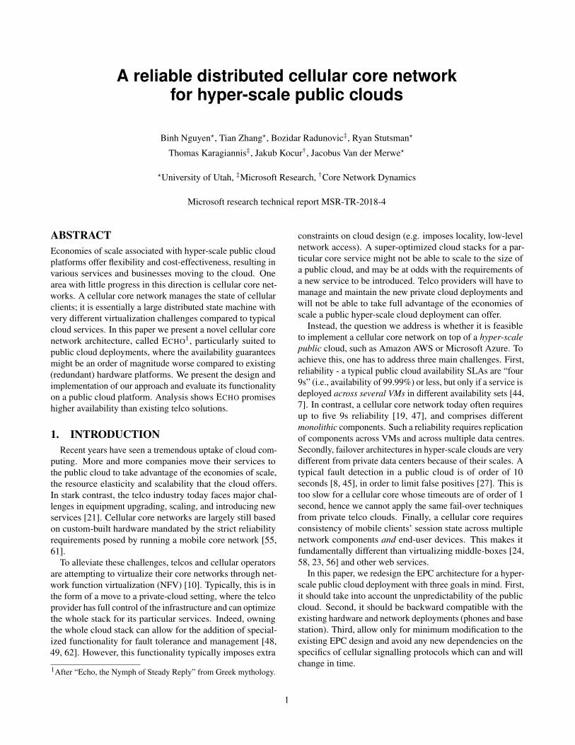
Figure 1: Service Request procedure in LTE/EPC. After setting up a RadioControl channel (i.e., RRC setup), the UE sends a Service Request to theMME. The MME modifies its UE context and sends a Modify Bearer Request(MBR) as a side effect request to the Serving Gateway (SGW). This sideeffect message sets up a tunnel endpoint for the UE on the SGW and triggersanother MBR to Packet Data Gateway (PGW) to set up a tunnel endpoint onthe PGW. If the MME doesn’t receive a reply, a timer expires and the MMEretries (msg. #3,4). When the PGW, SGW acknowledges the MME (msg.#6,7), the tunnel endpoints are past to the eNodeB (msg. #8.) that set up aE-UTRAN Radio Access Bearer (ERAB) at the eNodeB.
Component 1Request
Reply
Request
Reply}
Side effect (stateful change)
Request
ReplyLocalState/Timers
Component 2Local
State/Timers
Component 3Local
State/Timers}Side effect (stateful change)
Client/MobileDevice
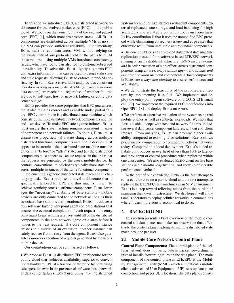
Figure 2: Distributed state in core mobile network. Components 1, 2 and 3map to the MME, the SGW and the PGW in Figure 1.
of a base station (eNodeB), Serving Gateway (SGW) anda Packet Gateway (PGW). Co-located with each data planecomponent is a control plane component (i.e., eNodeB-C,SGW-C, PGW-C) that coordinates with the MME and witheach other to implement a data path for the UE on the dataplane.UE context: The network stores an UE context for each at-tached UE which consists of subscriber information (authen-tication key, UE’s capability), the current state (connectedor idle), and the data connection (Evolved Packet Systembearer or EPS bearer) of the UE. The UE context is storedacross the control plane components; the MME stores all ofthe UE context, while the eNodeB-C, S/PGW-C only storeinformation of the data connection.
2.2 Mobile core: a distributed state machineThe cellular control plane implements a distributed state
machine for each UE, as illustrated on the Service Requestexample in Figure 1. The state machine is distributed acrossmultiple components and a transition may involve communi-cations and state changes across multiple other components.The control plane runs many such state machines in parallel,one for each UE. A generalized depiction of this distributedstate machine is in Figure 2.
Specifically, the distributed state machine deals with thefollowing events and messages:
Request from UE: Most of the changes in the state ma-chine are triggered by a client or mobile device. For example,when an idle UE has data to send, it sends a Service Request(message #1 in Figure 1) to the MME.
Side effect request & reply: Upon receiving a request
from a UE, the MME may alter the states at other components.In the Service Request example above, the MME must set upa bearer in the data plane. The MME sends a bearer setuprequest to the SGW (message #2) which triggers anotherrequest to the PGW (message #3). We call the messages thatare generated by components in the cellular core, and areindirectly triggered by the main request that originated in theUE, side effect requests.
Timers: A state transition can also be triggered by a time-out. For example, if a SGW does not respond to the bearersetup request, the MME will trigger a retry when its timerexpires (message #4). This retry generates another side effectrequest to the system. A timer can be set by any component,if so required by the protocol.
3. RELIABILITY IN CLOUD-BASED EPCThrough examples, we show the strict reliability require-
ments of the cellular core network. We then present the stateof the art of reliability in the current cellular core network.We contrast today’s cloud availability with hardware reliabil-ity through a 3-month long study.
3.1 Mobile network reliability requirementsWe conducted experiments with a Nexus 5 mobile device,
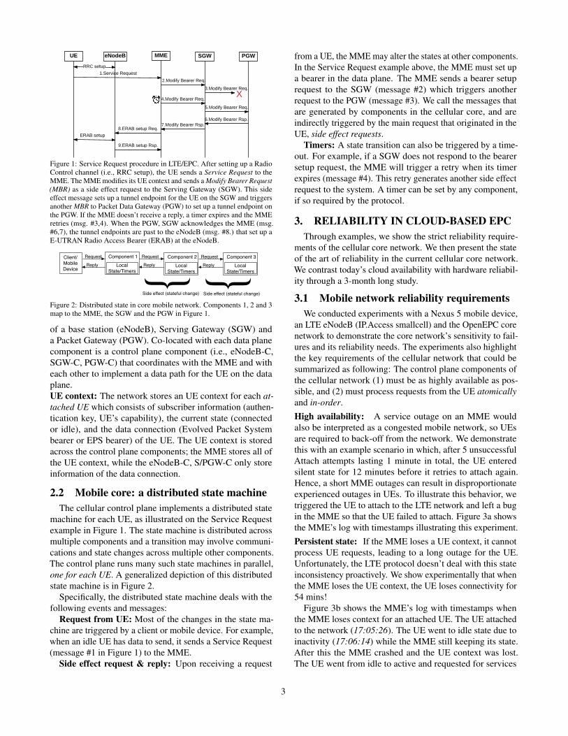
an LTE eNodeB (IP.Access smallcell) and the OpenEPC corenetwork to demonstrate the core network’s sensitivity to fail-ures and its reliability needs. The experiments also highlightthe key requirements of the cellular network that could besummarized as following: The control plane components ofthe cellular network (1) must be as highly available as pos-sible, and (2) must process requests from the UE atomicallyand in-order.High availability: A service outage on an MME wouldalso be interpreted as a congested mobile network, so UEsare required to back-off from the network. We demonstratethis with an example scenario in which, after 5 unsuccessfulAttach attempts lasting 1 minute in total, the UE enteredsilent state for 12 minutes before it retries to attach again.Hence, a short MME outages can result in disproportionateexperienced outages in UEs. To illustrate this behavior, wetriggered the UE to attach to the LTE network and left a bugin the MME so that the UE failed to attach. Figure 3a showsthe MME’s log with timestamps illustrating this experiment.Persistent state: If the MME loses a UE context, it cannotprocess UE requests, leading to a long outage for the UE.Unfortunately, the LTE protocol doesn’t deal with this stateinconsistency proactively. We show experimentally that whenthe MME loses the UE context, the UE loses connectivity for54 mins!
Figure 3b shows the MME’s log with timestamps whenthe MME loses context for an attached UE. The UE attachedto the network (17:05:26). The UE went to idle state due toinactivity (17:06:14) while the MME still keeping its state.After this the MME crashed and the UE context was lost.The UE went from idle to active and requested for services
3
13:09:47 mme_selection_pgw():331> Looking for [test.apn.epc] <failed>13:09:58 mme_selection_pgw():331> Looking for [test.apn.epc] <failed>13:10:10 mme_selection_pgw():331> Looking for [test.apn.epc] <failed>13:10:21 mme_selection_pgw():331> Looking for [test.apn.epc] <failed>13:10:33 mme_selection_pgw():331> Looking for [test.apn.epc] <failed>{UE times out for 12 minutes}13:22:34 mme_selection_pgw():331> Looking for [test.apn.epc] <failed>13:22:45 mme_selection_pgw():331> Looking for [test.apn.epc] <failed>
(a)
17:05:26 mme_sm():1725> [1:NAS__Attach_complete]17:06:14 mme_sm():1746> [59:S1__UE_Context_release_complete]{ MME crashed, UE's state on MME was lost}{ UE has data to send, trigger a Service Request}17:10:01 mme_sm():1925> [09:EMM__Service_request] <failed>{UE has no service for 54 minutes}{ Periodical Tracking Area Update (TAU) timer (T3412) on UE times out after 54 minutes from the last Attach Complete. This triggers a TAU procedure}18:00:15 mme_sm():1725> [16:NAS__Tracking_area_update_request] <failed>{ TAU request timed-out. UE triggers Attach Request}18:00:30 mme_sm():1725> [2:NAS__Attach_request] <suceeded>18:00:31 mme_sm():1725> [1:NAS__Attach_complete]18:02:05 mme_sm():1925> [09:EMM__Service_request] <suceeded>{ UE has service}
(b)
11:01:57 mme_sm():1725> [2:NAS__Attach_request]11:01:58 mme_sm():1725> [1:NAS__Attach_complete]{ UE attached}{ UE switches OFF, triggers a Detach procedure}11:03:45 mme_sm():1725> [6:NAS__Detach_request] <delayed 60s>{ MME thread #1 received Detach Request, and holds for 60s without a progress}{ UE switches ON, triggers an Attach procedure}11:03:58 mme_sm():1725> [2:NAS__Attach_request] 11:03:59 mme_sm():1725> [1:NAS__Attach_complete] <suceeded>{ MME thread #2 received and processed the Attach Request sucessfully}11:04:45 mme_sm():1725> [6:NAS__Detach_accept] <suceeded>{ After 60s, MME thread #1 processed the stale Detach Request, and suceeded}{ UE is detached from the network}11:06:05 mme_sm():1925> [09:EMM__Service_request] <failed>{UE has no service for 54 minutes}
(c)Figure 3: Examples of real-world outages caused by reliability issues: (a) 5 consecutive Attach failures caused UE to sleep for 12 mins; (b) UE did not haveservice for 54 minutes because MME crashed and UE context was lost; (c) Violation of FIFO order execution caused state inconsistency and 54 minutes outage.
but did not get any service for 54 mins (from 17:10:01 to17:54:03). 54 mins after the Attach, the UE performed aperiodic Tracking Area Update (TAU) procedure (18:00:15)as defined in its protocol. This TAU also failed because theMME does not have any context of the UE. The result ofthis unsuccessful TAU is that the UE timed out and movedto a “deregisterd” state which requires the UE to reattach [2](18:00:30). The Attach Request let the UE exchanged itscontext with the MME. After having the UE context, theMME was able to serve the UE as normal (18:02:05), endingthe extended UE service outage.In-order message delivery and execution: If the mobilecore network execute requests from the UE in an out-of-ordermanner, the state between the network and the UE will beinconsistent which leads to a long outage. We demonstratethis with an experiment in which a UE requests 〈R1,R2〉but the network executes the requests in a different order(i.e., 〈R2,R1〉). This causes state inconsistency between thenetwork and the UE which results in a long outage.
Figure 3c shows the MME’s log with timestamps describ-ing this experiment. After attaching to the network, the ra-dio interface of the UE was turned off to trigger a detach(11:03:45). That detach was processed by a MME1 threadwhich is a slow MME thread. Later the UE was turned on totrigger another attach request which arrived at MME2 thread(11:03:58), updating the state of the UE Context with the At-tached state. This was successfully verified by the MME2 andreplied to (11:03:59). However, the slow MME1 thread laterwas executed and updated the UE Context with Detachedstate (11:04:45). The Detached Accept message was ignoredby the UE. This results in an inconsistent state between thenetwork (Detached) and the UE (Attached). This caused aUE outage of 54 mins as in our previous experiment.
3.2 Reliable EPC: state of the artTelecom-grade reliable hardware is built with N +M re-
dundancy [19, 46, 64, 47]. Active-standby techniques [36]allow for state synchronization (e.g., UE context) betweenthe active and standby instances with the active one switchingover to the standby one in case of a failure. This techniqueis extended to an NFV setting where a resource schedulercan quickly detect a fault and migrate service from a faulty
component [48, 49, 62].Further redundancy is introduced at the protocol layer. The
standard EPC architecture supports a pool of MMEs [4] be-hind a load balancer. If one MME instance fails, the eNodeBwill notice that its Stream Control Transmission Protocol(SCTP) connection to MME is broken and connect to anotherMME instance in the pool. State (UE context) is either storedin a common Session Restoration Server (SRS) [39, 38] orsynchronously replicated among MME instances [19]. Thismechanism, however, doesn’t deal with the out-of-order ex-ecution problem. For example, if the SCTP connection ofa MME instance is broken (e.g., because of a network cardcrash) while the instance is still active, the instance couldgenerate stale requests that might cause inconsistency.
There are several aspects of the existing designs whichdo not map well to the public cloud infrastructure. In orderto allows for almost instantaneous fault isolation and repair,hardware appliances and VNFs offer fine-grained availabil-ity information and scheduling control (active standby orservice migration), low-level network access and assume lo-cality among instances of the same VNF. However, thesetechniques do not apply to hyper-scale public clouds, whereinstances often do not share the same rack, faults detectionare much slower because of false positives [8, 45, 27] andnetwork virtualization prevents standard approaches for faultmigration [33].
Furthermore, due to higher inherent reliability of conven-tional nodes, the types of faults that can occur are different.Public clouds run all software on VMs that can delay ex-ecutions (e.g., due to an upgrade), causing stale requestsand inconsistent side-requests (as in example 3c). Overall, apublic cloud EPC deployment has to deal with failures proac-tively and in software. Our failure measurements in the nextsection also suggest this.
3.3 Availability of public cloudsCloud providers, such as AWS and Azure, do not advertise
availabilities of individual VMs but only of “availability sets”of carefully selected VMs that belong to different fault andupgrade domains. Even so, the advertise availability is “four9s” – an order of magnitude larger total outage comparedto the five 9s availability of telco appliances. Besides theoverall availability in the number of 9s, the mobile network
4
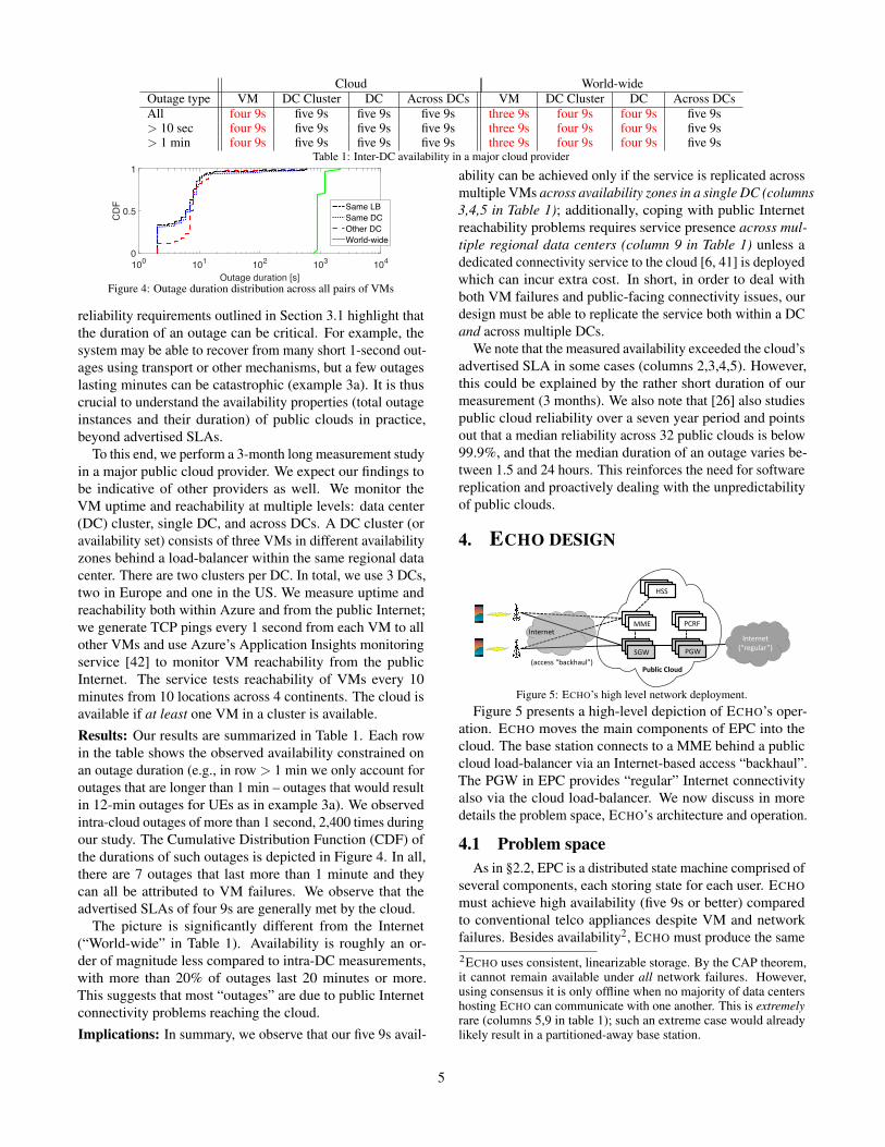
Cloud World-wideOutage type VM DC Cluster DC Across DCs VM DC Cluster DC Across DCsAll four 9s five 9s five 9s five 9s three 9s four 9s four 9s five 9s> 10 sec four 9s five 9s five 9s five 9s three 9s four 9s four 9s five 9s> 1 min four 9s five 9s five 9s five 9s three 9s four 9s four 9s five 9s
Table 1: Inter-DC availability in a major cloud provider
Outage duration [s]100 101 102 103 104
CD
F
0
0.5
1
Same LBSame DCOther DCWorld-wide
Figure 4: Outage duration distribution across all pairs of VMs
reliability requirements outlined in Section 3.1 highlight thatthe duration of an outage can be critical. For example, thesystem may be able to recover from many short 1-second out-ages using transport or other mechanisms, but a few outageslasting minutes can be catastrophic (example 3a). It is thuscrucial to understand the availability properties (total outageinstances and their duration) of public clouds in practice,beyond advertised SLAs.
To this end, we perform a 3-month long measurement studyin a major public cloud provider. We expect our findings tobe indicative of other providers as well. We monitor theVM uptime and reachability at multiple levels: data center(DC) cluster, single DC, and across DCs. A DC cluster (oravailability set) consists of three VMs in different availabilityzones behind a load-balancer within the same regional datacenter. There are two clusters per DC. In total, we use 3 DCs,two in Europe and one in the US. We measure uptime andreachability both within Azure and from the public Internet;we generate TCP pings every 1 second from each VM to allother VMs and use Azure’s Application Insights monitoringservice [42] to monitor VM reachability from the publicInternet. The service tests reachability of VMs every 10minutes from 10 locations across 4 continents. The cloud isavailable if at least one VM in a cluster is available.Results: Our results are summarized in Table 1. Each rowin the table shows the observed availability constrained onan outage duration (e.g., in row > 1 min we only account foroutages that are longer than 1 min – outages that would resultin 12-min outages for UEs as in example 3a). We observedintra-cloud outages of more than 1 second, 2,400 times duringour study. The Cumulative Distribution Function (CDF) ofthe durations of such outages is depicted in Figure 4. In all,there are 7 outages that last more than 1 minute and theycan all be attributed to VM failures. We observe that theadvertised SLAs of four 9s are generally met by the cloud.
The picture is significantly different from the Internet(“World-wide” in Table 1). Availability is roughly an or-der of magnitude less compared to intra-DC measurements,with more than 20% of outages last 20 minutes or more.This suggests that most “outages” are due to public Internetconnectivity problems reaching the cloud.Implications: In summary, we observe that our five 9s avail-
ability can be achieved only if the service is replicated acrossmultiple VMs across availability zones in a single DC (columns3,4,5 in Table 1); additionally, coping with public Internetreachability problems requires service presence across mul-tiple regional data centers (column 9 in Table 1) unless adedicated connectivity service to the cloud [6, 41] is deployedwhich can incur extra cost. In short, in order to deal withboth VM failures and public-facing connectivity issues, ourdesign must be able to replicate the service both within a DCand across multiple DCs.
We note that the measured availability exceeded the cloud’sadvertised SLA in some cases (columns 2,3,4,5). However,this could be explained by the rather short duration of ourmeasurement (3 months). We also note that [26] also studiespublic cloud reliability over a seven year period and pointsout that a median reliability across 32 public clouds is below99.9%, and that the median duration of an outage varies be-tween 1.5 and 24 hours. This reinforces the need for softwarereplication and proactively dealing with the unpredictabilityof public clouds.
4. ECHO DESIGN
MME
SGW PGWInternet
(“regular”)
HSS
PCRF
SGWSGW PGWPGW
PCRFPCRFMMEMME
HSSHSS
Public'Cloud
Internet
(access:“backhaul”)
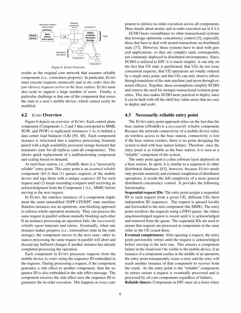
Figure 5: ECHO’s high level network deployment.
Figure 5 presents a high-level depiction of ECHO’s oper-ation. ECHO moves the main components of EPC into thecloud. The base station connects to a MME behind a publiccloud load-balancer via an Internet-based access “backhaul”.The PGW in EPC provides “regular” Internet connectivityalso via the cloud load-balancer. We now discuss in moredetails the problem space, ECHO’s architecture and operation.
4.1 Problem spaceAs in §2.2, EPC is a distributed state machine comprised of
several components, each storing state for each user. ECHOmust achieve high availability (five 9s or better) comparedto conventional telco appliances despite VM and networkfailures. Besides availability2, ECHO must produce the same2ECHO uses consistent, linearizable storage. By the CAP theorem,it cannot remain available under all network failures. However,using consensus it is only offline when no majority of data centershosting ECHO can communicate with one another. This is extremelyrare (columns 5,9 in table 1); such an extreme case would alreadylikely result in a partitioned-away base station.
5
1
n
LB
Highly AvailablePersistent
Storage
Component 1
Component 2
{Statelessprocessing {
State
{Idempotentside effects
Base station
entry point
{"Necessary reliable"device proxy
MobileDevice
Component 3
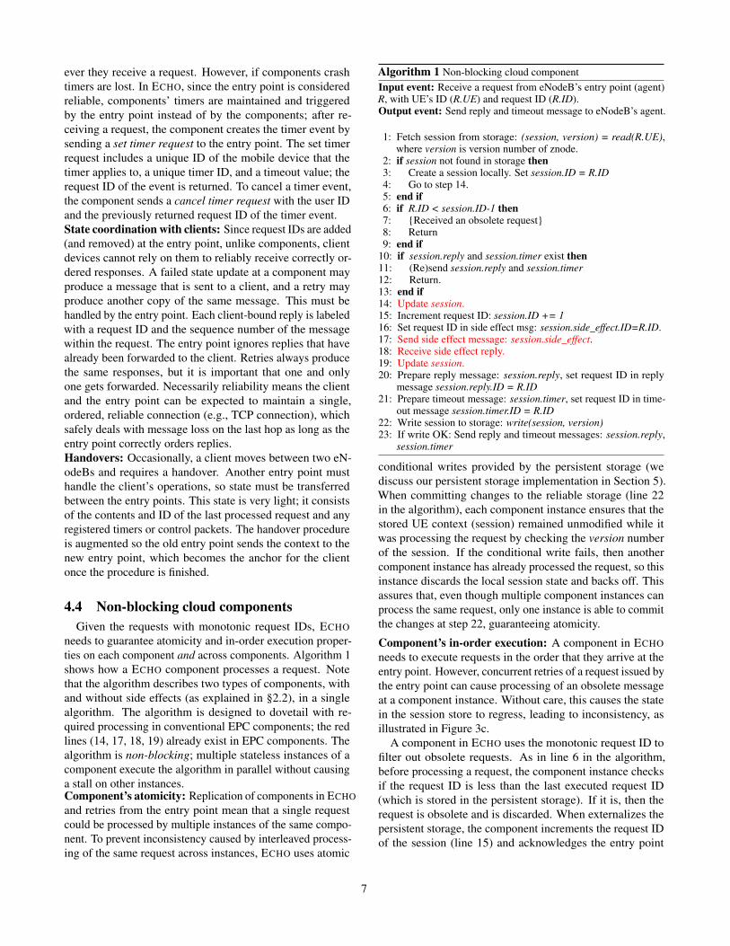
Figure 6: ECHO Overview
results as the original core network that assumes reliablecomponents (i.e., correctness property). In particular, ECHOmust execute requests atomically and in the order that the(per-device) requests arrive at the base station. ECHO mustalso scale to support a large number of users. Finally, aparticular challenge is that one of the component that storesthe state is a user’s mobile device, which cannot easily bemodified.
4.2 ECHO OverviewFigure 6 depicts an overview of ECHO. Each control plane
component (Components 1, 2 and 3 that correspond to MME,SGW, and PGW) is replicated (instances 1 to n) behind adata center load balancer (LB) [50, 40]. Each componentinstance is refactored into a stateless processing frontend,paired with a high availability persistent storage backend thatmaintains state for all replicas (and all components). Thisallows quick replacement of a malfunctioning componentand scaling based on demand.
At each base station, i.e., eNodeB, there is a “necessarilyreliable” entry point. This entry point is an assumed reliablecomponent (§4.3) that (1) queues requests of the mobiledevice and tags them with a unique sequence ID for eachrequest and (2) keeps resending a request until receiving anacknowledgment from the Component 1 (i.e., MME) beforemoving to the next request.
In ECHO, the stateless instances of a component imple-ment the same unmodified 3GPP LTE/EPC state machine.Stateless instances use an optimistic, non-blocking approachto enforce whole-operation atomicity. They can process thesame request in parallel without mutually blocking each other.If an instance processing an operation fails, the necessarilyreliable agent timeouts and retries. Eventually, when oneinstance makes progress (i.e., externalizes state in the statestorage), the component moves to the next state; other in-stances processing the same request in parallel will abort anddiscard any buffered changes if another instance has alreadycompleted processing the operation.
Each component in ECHO processes requests from themobile device in-order using the sequence ID embedded inthe requests. During processing a request, if the componentgenerates a side effect to another component, then the se-quence ID is also embedded in the side effect message. Thecomponent receives the side effect uses the sequence ID toguarantee the in-order execution. This happens at every com-
ponent to enforce in-order execution across all components.More details about atomic and in-order execution are in § 4.4.
ECHO bears resemblance to other transactional systemsthat leverage optimistic concurrency control [5], especiallythose that have to deal with nested transactions on distributedstate [37]. However, those systems have to deal with gen-eral applications, so they are complex (and, consequently,not commonly deployed in distributed environments). Since,ECHO is tailored to EPC it is much simpler: it can rely onthe fact that UE state is partitioned, that UEs do not issueconcurrent requests, that UE operations are totally orderedby a single entry point, and that UEs can only observe effectsthrough transitions of the state machine (and never through ex-ternal effects). Together, these assumptions simplify ECHOand remove the need for stronger transactional isolation prop-erties. This also makes ECHO more practical to deploy sinceit can be built with off-the-shelf key-value stores that are easyto deploy and scale.
4.3 Necessarily reliable entry pointThe ECHO entry point approach relies on the fact that the
base station (eNodeB) is a necessarily reliable component.Because the network connectivity of a mobile device relieson wireless access to the base station, connectivity is lostif the base station crashes; there is no point designing thesystem to deal with base station failures. Therefore, since theentry point is as reliable as the base station, it is seen as a“reliable” component of the system.
The entry point agent is a thin software layer deployed ona base station. In spirit, it is similar to a sequencer in otherdistributed databases [63], however, because ECHO needsonly provide atomicity and eventual completion of distributedoperations, it avoids the full complexity of a more generaldistributed concurrency control. It provides the followingfunctionality.Sequential request IDs: The entry point assigns a sequentialID to each request from a given UE; different UEs haveindependent ID sequences. The request is queued locallyand forwarded to the next component (the MME). The entrypoint serializes the requests using a FIFO queue: the oldestunacknowledged request is resent until it is acknowledgedand removed from the queue. The sequential IDs are used toensure that requests are processed at components in the sameorder as the UE issued them.Eventual completeness: After queuing a request, the entrypoint persistently retries until the request is acknowledgedbefore moving to the next one. This ensures a componentfailure in the cloud won’t be visible to the mobile device; if aninstance of a component crashes in the middle of an operation,the entry point transparently issues a retry and the retry willreach another instance of that component to recover fromthe crash. As the entry point is the “reliable” component,its retries ensure a request is eventually processed and isprocessed by all core components regardless of failures.Reliable timers: Components in EPC must set a timer when-
6
ever they receive a request. However, if components crashtimers are lost. In ECHO, since the entry point is consideredreliable, components’ timers are maintained and triggeredby the entry point instead of by the components; after re-ceiving a request, the component creates the timer event bysending a set timer request to the entry point. The set timerrequest includes a unique ID of the mobile device that thetimer applies to, a unique timer ID, and a timeout value; therequest ID of the event is returned. To cancel a timer event,the component sends a cancel timer request with the user IDand the previously returned request ID of the timer event.State coordination with clients: Since request IDs are added(and removed) at the entry point, unlike components, clientdevices cannot rely on them to reliably receive correctly or-dered responses. A failed state update at a component mayproduce a message that is sent to a client, and a retry mayproduce another copy of the same message. This must behandled by the entry point. Each client-bound reply is labeledwith a request ID and the sequence number of the messagewithin the request. The entry point ignores replies that havealready been forwarded to the client. Retries always producethe same responses, but it is important that one and onlyone gets forwarded. Necessarily reliability means the clientand the entry point can be expected to maintain a single,ordered, reliable connection (e.g., TCP connection), whichsafely deals with message loss on the last hop as long as theentry point correctly orders replies.Handovers: Occasionally, a client moves between two eN-odeBs and requires a handover. Another entry point musthandle the client’s operations, so state must be transferredbetween the entry points. This state is very light; it consistsof the contents and ID of the last processed request and anyregistered timers or control packets. The handover procedureis augmented so the old entry point sends the context to thenew entry point, which becomes the anchor for the clientonce the procedure is finished.
4.4 Non-blocking cloud componentsGiven the requests with monotonic request IDs, ECHO
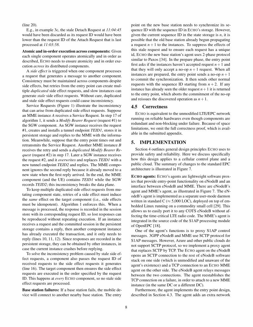
needs to guarantee atomicity and in-order execution proper-ties on each component and across components. Algorithm 1shows how a ECHO component processes a request. Notethat the algorithm describes two types of components, withand without side effects (as explained in §2.2), in a singlealgorithm. The algorithm is designed to dovetail with re-quired processing in conventional EPC components; the redlines (14, 17, 18, 19) already exist in EPC components. Thealgorithm is non-blocking; multiple stateless instances of acomponent execute the algorithm in parallel without causinga stall on other instances.Component’s atomicity: Replication of components in ECHOand retries from the entry point mean that a single requestcould be processed by multiple instances of the same compo-nent. To prevent inconsistency caused by interleaved process-ing of the same request across instances, ECHO uses atomic
Algorithm 1 Non-blocking cloud componentInput event: Receive a request from eNodeB’s entry point (agent)R, with UE’s ID (R.UE) and request ID (R.ID).Output event: Send reply and timeout message to eNodeB’s agent.
1: Fetch session from storage: (session, version) = read(R.UE),where version is version number of znode.
2: if session not found in storage then3: Create a session locally. Set session.ID = R.ID4: Go to step 14.5: end if6: if R.ID < session.ID-1 then7: {Received an obsolete request}8: Return9: end if
10: if session.reply and session.timer exist then11: (Re)send session.reply and session.timer12: Return.13: end if14: Update session.15: Increment request ID: session.ID += 116: Set request ID in side effect msg: session.side_effect.ID=R.ID.17: Send side effect message: session.side_effect.18: Receive side effect reply.19: Update session.20: Prepare reply message: session.reply, set request ID in reply
message session.reply.ID = R.ID21: Prepare timeout message: session.timer, set request ID in time-
out message session.timer.ID = R.ID22: Write session to storage: write(session, version)23: If write OK: Send reply and timeout messages: session.reply,
session.timer
conditional writes provided by the persistent storage (wediscuss our persistent storage implementation in Section 5).When committing changes to the reliable storage (line 22in the algorithm), each component instance ensures that thestored UE context (session) remained unmodified while itwas processing the request by checking the version numberof the session. If the conditional write fails, then anothercomponent instance has already processed the request, so thisinstance discards the local session state and backs off. Thisassures that, even though multiple component instances canprocess the same request, only one instance is able to committhe changes at step 22, guaranteeing atomicity.
Component’s in-order execution: A component in ECHOneeds to execute requests in the order that they arrive at theentry point. However, concurrent retries of a request issued bythe entry point can cause processing of an obsolete messageat a component instance. Without care, this causes the statein the session store to regress, leading to inconsistency, asillustrated in Figure 3c.
A component in ECHO uses the monotonic request ID tofilter out obsolete requests. As in line 6 in the algorithm,before processing a request, the component instance checksif the request ID is less than the last executed request ID(which is stored in the persistent storage). If it is, then therequest is obsolete and is discarded. When externalizes thepersistent storage, the component increments the request IDof the session (line 15) and acknowledges the entry point
7
(line 20).E.g., in example 3c, the stale Detach Request at 11:04:45
would have been discarded as its request ID would have beenlower than the request ID of the Attach Request that is lastprocessed at 11:03:58.
Atomic and in-order execution across components: Giveneach single component operates atomically and in order asdescribed, ECHO needs to ensure atomicity and in order exe-cution across its distributed components.
A side effect is triggered when one component processesa request that generates a message to another component.Consistency must be maintained across components despiteside effects, but retries from the entry point can create mul-tiple duplicated side effect requests, and slow instances cangenerate stale side effect requests. Without care, duplicatedand stale side effect requests could cause inconsistency.
Service Requests (Figure 1) illustrate the inconsistencythat can arise from duplicated side effect requests. Supposean MME instance A receives a Service Request. In step 17 ofalgorithm 1, it sends a Modify Bearer Request (request #1) tothe SGW component. An SGW instance receives the request#1, creates and installs a tunnel endpoint TEID1, stores it inpersistent storage and replies to the MME with the informa-tion. Meanwhile, suppose that the entry point times out andretransmits the Service Request. Another MME instance Breceives the retry and sends a duplicated Modify Bearer Re-quest (request #2) in step 17. Later a SGW instance receivesthe request #2, and it overwrites and replaces TEID1 with anew tunnel endpoint TEID2 and replies. The MME compo-nent ignores the second reply because it already moved to anew state when the first reply arrived. In the end, the MMEcomponent (and the UE) contains TEID1 while the SGWrecords TEID2; this inconsistency breaks the data plane.
To keep multiple duplicated side effect requests from mu-tating component state, retries of a side effect must inducethe same effect on the target component (i.e., side effectsmust be idempotent). Algorithm 1 enforces this. When amessage is processed, the response is recorded in the sessionstore with its corresponding request ID, so lost responses canbe reproduced without repeating execution. If an instancereceives a request and the committed session in the persistentstorage contains a reply, then another component instancehas already executed the transaction, and it only needs toreply (lines 10, 11, 12). Since responses are recorded in thepersistent storage, they can be obtained by other instances, incase the current instance crashes before replying.
To solve the inconsistency problem caused by stale side ef-fect requests, a component also passes the request ID ofreceived requests to the side effect requests it generates(line 16). The target component then ensures the side effectrequests are executed in the order specified by the requestID. This happens at every ECHO component, so no stale sideeffect requests are processed.
Base station failures: If a base station fails, the mobile de-vice will connect to another nearby base station. The entry
point on the new base station needs to synchronize its se-quence ID with the sequence ID in ECHO’s storage. However,given the current sequence ID in the state storage is n, it ispossible that the old base station already begun propagatinga request n+ 1 to the instances. To suppress the effects ofthis stale request and to ensure each request has a uniqueid, ECHO the new base station’s agent uses 2-phase protocolsimilar to Paxos [34]. In the prepare phase, the entry pointfirst asks if the instances haven’t accepted request n+1 andthat they will only accept a no-op n+ 1 request. When allinstances are prepared, the entry point sends a no-op n+ 1to commit the synchronization. It then sends other normalrequests with the sequence ID starting from n+ 2. If anyinstance has already seen the older request n+1 it is returnedto the entry point, which aborts the commitment of the no-opand reissues the discovered operation as n+1.
4.5 CorrectnessECHO is equivalent to the unmodified LTE/EPC network
running on reliable hardwares even though components areredundant and non-blocking under failure. Because of spacelimitations, we omit the full correctness proof, which is avail-able in the submitted appendix.
5. IMPLEMENTATIONSection 4 outlines general design principles ECHO uses to
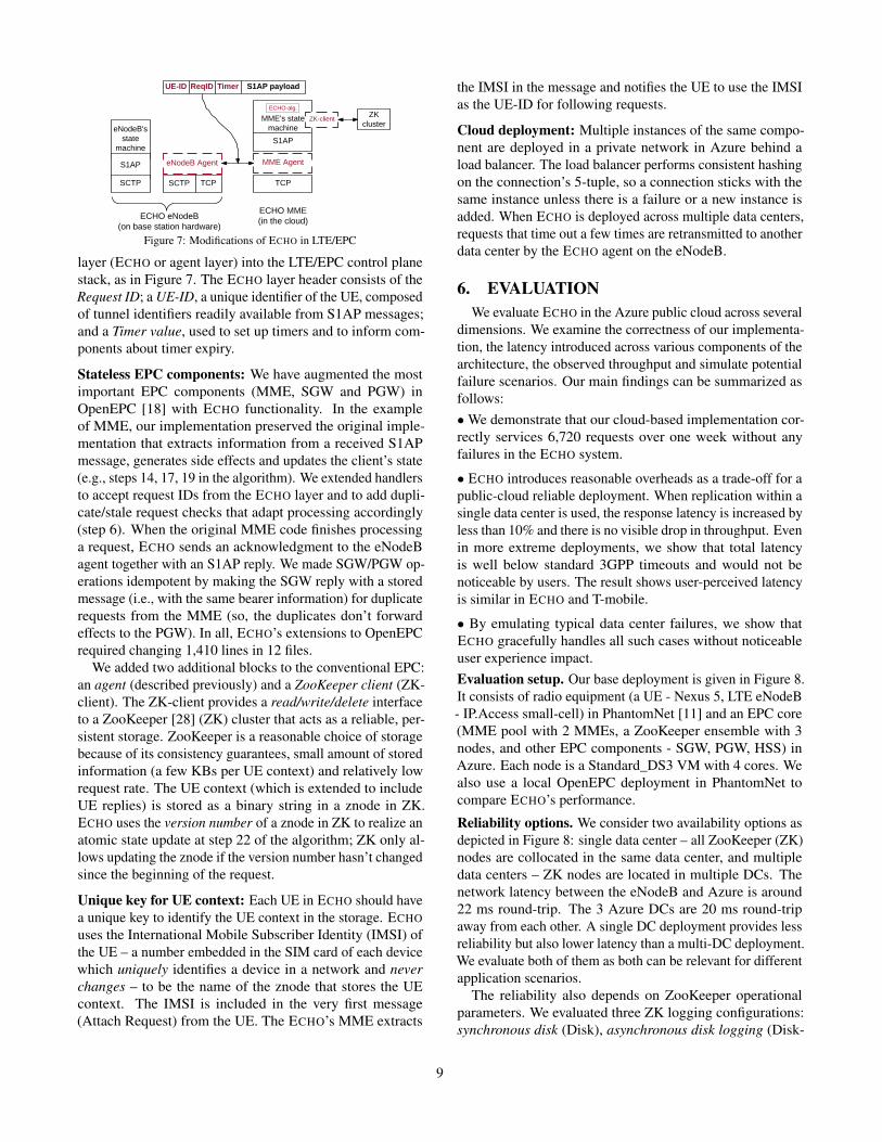
provide safety and reliability. Here we discuss specificallyhow this design applies to a cellular control plane and apublic cloud. The summary of changes to the standard EPCarchitecture is illustrated in Figure 7.
ECHO agents: ECHO’s agents are lightweight software prox-ies that provide entry-point functionality on eNodeB and aninterface between eNodeB and MME. There are eNodeB’sagent and MME’s agent, as illustrated in Figure 7. The eN-odeB’s agent is implemented as a separate user-mode daemonwritten in standard C (≈ 5,000 LOC), deployed on top of em-bedded Linux running on a commodity small cell [29]. Thisallows us to easily port it to any COTS eNodeB without af-fecting the time-critical LTE radio code. The MME’s agent isintegrated in the source code of the S1AP processing moduleof OpenEPC [18].
One of the agent’s functions is to proxy S1AP controlmessages. 3GPP eNodeB and MME use SCTP protocol forS1AP messages. However, Azure and other public clouds donot support SCTP protocol, so we implement a proxy agentthat replaces SCTP by TCP. The ECHO agent on the eNodeBopens an SCTP connection to the rest of eNodeB softwarestack on one side (which is unmodified and unaware of theagent’s existence) and a TCP connection to an ECHO MMEagent on the other side. The eNodeB agent relays messagesbetween the two connections. The agent reestablishes theTCP connection on a failure, in order to attach to a new MMEinstance (in the same DC or a different DC).
Furthermore, the agent implements the entry point design,described in Section 4.3. The agent adds an extra network
8
MME Agent
S1AP
TCP
UE-ID ReqID Timer
ZK-client ZK cluster
eNodeB Agent
eNodeB's state
machine
S1AP
SCTP
S1AP payload
ECHO MME(in the cloud)
SCTP TCP
ECHO eNodeB (on base station hardware)
MME's state machine
ECHO-alg.
Figure 7: Modifications of ECHO in LTE/EPC
layer (ECHO or agent layer) into the LTE/EPC control planestack, as in Figure 7. The ECHO layer header consists of theRequest ID; a UE-ID, a unique identifier of the UE, composedof tunnel identifiers readily available from S1AP messages;and a Timer value, used to set up timers and to inform com-ponents about timer expiry.
Stateless EPC components: We have augmented the mostimportant EPC components (MME, SGW and PGW) inOpenEPC [18] with ECHO functionality. In the exampleof MME, our implementation preserved the original imple-mentation that extracts information from a received S1APmessage, generates side effects and updates the client’s state(e.g., steps 14, 17, 19 in the algorithm). We extended handlersto accept request IDs from the ECHO layer and to add dupli-cate/stale request checks that adapt processing accordingly(step 6). When the original MME code finishes processinga request, ECHO sends an acknowledgment to the eNodeBagent together with an S1AP reply. We made SGW/PGW op-erations idempotent by making the SGW reply with a storedmessage (i.e., with the same bearer information) for duplicaterequests from the MME (so, the duplicates don’t forwardeffects to the PGW). In all, ECHO’s extensions to OpenEPCrequired changing 1,410 lines in 12 files.
We added two additional blocks to the conventional EPC:an agent (described previously) and a ZooKeeper client (ZK-client). The ZK-client provides a read/write/delete interfaceto a ZooKeeper [28] (ZK) cluster that acts as a reliable, per-sistent storage. ZooKeeper is a reasonable choice of storagebecause of its consistency guarantees, small amount of storedinformation (a few KBs per UE context) and relatively lowrequest rate. The UE context (which is extended to includeUE replies) is stored as a binary string in a znode in ZK.ECHO uses the version number of a znode in ZK to realize anatomic state update at step 22 of the algorithm; ZK only al-lows updating the znode if the version number hasn’t changedsince the beginning of the request.
Unique key for UE context: Each UE in ECHO should havea unique key to identify the UE context in the storage. ECHOuses the International Mobile Subscriber Identity (IMSI) ofthe UE – a number embedded in the SIM card of each devicewhich uniquely identifies a device in a network and neverchanges – to be the name of the znode that stores the UEcontext. The IMSI is included in the very first message(Attach Request) from the UE. The ECHO’s MME extracts
the IMSI in the message and notifies the UE to use the IMSIas the UE-ID for following requests.
Cloud deployment: Multiple instances of the same compo-nent are deployed in a private network in Azure behind aload balancer. The load balancer performs consistent hashingon the connection’s 5-tuple, so a connection sticks with thesame instance unless there is a failure or a new instance isadded. When ECHO is deployed across multiple data centers,requests that time out a few times are retransmitted to anotherdata center by the ECHO agent on the eNodeB.
6. EVALUATIONWe evaluate ECHO in the Azure public cloud across several
dimensions. We examine the correctness of our implementa-tion, the latency introduced across various components of thearchitecture, the observed throughput and simulate potentialfailure scenarios. Our main findings can be summarized asfollows:•We demonstrate that our cloud-based implementation cor-rectly services 6,720 requests over one week without anyfailures in the ECHO system.
• ECHO introduces reasonable overheads as a trade-off for apublic-cloud reliable deployment. When replication within asingle data center is used, the response latency is increased byless than 10% and there is no visible drop in throughput. Evenin more extreme deployments, we show that total latencyis well below standard 3GPP timeouts and would not benoticeable by users. The result shows user-perceived latencyis similar in ECHO and T-mobile.
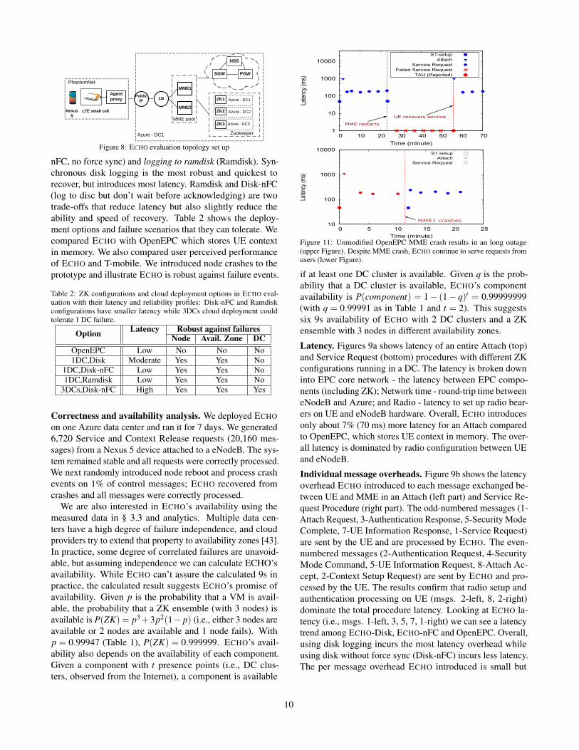
• By emulating typical data center failures, we show thatECHO gracefully handles all such cases without noticeableuser experience impact.Evaluation setup. Our base deployment is given in Figure 8.It consists of radio equipment (a UE - Nexus 5, LTE eNodeB- IP.Access small-cell) in PhantomNet [11] and an EPC core(MME pool with 2 MMEs, a ZooKeeper ensemble with 3nodes, and other EPC components - SGW, PGW, HSS) inAzure. Each node is a Standard_DS3 VM with 4 cores. Wealso use a local OpenEPC deployment in PhantomNet tocompare ECHO’s performance.
Reliability options. We consider two availability options asdepicted in Figure 8: single data center – all ZooKeeper (ZK)nodes are collocated in the same data center, and multipledata centers – ZK nodes are located in multiple DCs. Thenetwork latency between the eNodeB and Azure is around22 ms round-trip. The 3 Azure DCs are 20 ms round-tripaway from each other. A single DC deployment provides lessreliability but also lower latency than a multi-DC deployment.We evaluate both of them as both can be relevant for differentapplication scenarios.
The reliability also depends on ZooKeeper operationalparameters. We evaluated three ZK logging configurations:synchronous disk (Disk), asynchronous disk logging (Disk-
9
ZK2MME2
LB
ZK3
ZK1Public
IP
Azure - DC1
Agent proxy
PhantomNetMME1
SGW PGW
HSS
Azure - DC1
Azure - DC3
Azure - DC2
Zookeeper
LTE small cellNexus 5
MME pool
Figure 8: ECHO evaluation topology set up
nFC, no force sync) and logging to ramdisk (Ramdisk). Syn-chronous disk logging is the most robust and quickest torecover, but introduces most latency. Ramdisk and Disk-nFC(log to disc but don’t wait before acknowledging) are twotrade-offs that reduce latency but also slightly reduce theability and speed of recovery. Table 2 shows the deploy-ment options and failure scenarios that they can tolerate. Wecompared ECHO with OpenEPC which stores UE contextin memory. We also compared user perceived performanceof ECHO and T-mobile. We introduced node crashes to theprototype and illustrate ECHO is robust against failure events.
Table 2: ZK configurations and cloud deployment options in ECHO eval-uation with their latency and reliability profiles: Disk-nFC and Ramdiskconfigurations have smaller latency while 3DCs cloud deployment couldtolerate 1 DC failure.
Option Latency Robust against failuresNode Avail. Zone DC
OpenEPC Low No No No1DC,Disk Moderate Yes Yes No
1DC,Disk-nFC Low Yes Yes No1DC,Ramdisk Low Yes Yes No
3DCs,Disk-nFC High Yes Yes Yes
Correctness and availability analysis. We deployed ECHOon one Azure data center and ran it for 7 days. We generated6,720 Service and Context Release requests (20,160 mes-sages) from a Nexus 5 device attached to a eNodeB. The sys-tem remained stable and all requests were correctly processed.We next randomly introduced node reboot and process crashevents on 1% of control messages; ECHO recovered fromcrashes and all messages were correctly processed.
We are also interested in ECHO’s availability using themeasured data in § 3.3 and analytics. Multiple data cen-ters have a high degree of failure independence, and cloudproviders try to extend that property to availability zones [43].In practice, some degree of correlated failures are unavoid-able, but assuming independence we can calculate ECHO’savailability. While ECHO can’t assure the calculated 9s inpractice, the calculated result suggests ECHO’s promise ofavailability. Given p is the probability that a VM is avail-able, the probability that a ZK ensemble (with 3 nodes) isavailable is P(ZK) = p3+3p2(1− p) (i.e., either 3 nodes areavailable or 2 nodes are available and 1 node fails). Withp = 0.99947 (Table 1), P(ZK) = 0.999999. ECHO’s avail-ability also depends on the availability of each component.Given a component with t presence points (i.e., DC clus-ters, observed from the Internet), a component is available
1
10
100
1000
10000
0 10 20 30 40 50 60 70
Late
ncy
(ms)
Time (minute)
S1-setupAttach
Service RequestFailed Service Request
TAU (Rejected)
MME restarts
UE recovers service
10
100
1000
10000
0 5 10 15 20 25
Late
ncy (
ms)
Time (minute)
S1 setupAttach
Service Request
MME1 crashes
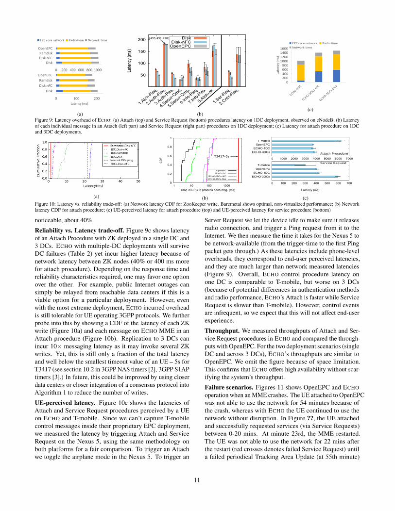
Figure 11: Unmodified OpenEPC MME crash results in an long outage(upper Figure). Despite MME crash, ECHO continue to serve requests fromusers (lower Figure).
if at least one DC cluster is available. Given q is the prob-ability that a DC cluster is available, ECHO’s componentavailability is P(component) = 1− (1− q)t = 0.99999999(with q = 0.99991 as in Table 1 and t = 2). This suggestssix 9s availability of ECHO with 2 DC clusters and a ZKensemble with 3 nodes in different availability zones.
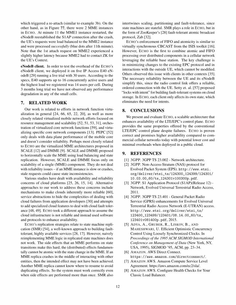
Latency. Figures 9a shows latency of an entire Attach (top)and Service Request (bottom) procedures with different ZKconfigurations running in a DC. The latency is broken downinto EPC core network - the latency between EPC compo-nents (including ZK); Network time - round-trip time betweeneNodeB and Azure; and Radio - latency to set up radio bear-ers on UE and eNodeB hardware. Overall, ECHO introducesonly about 7% (70 ms) more latency for an Attach comparedto OpenEPC, which stores UE context in memory. The over-all latency is dominated by radio configuration between UEand eNodeB.
Individual message overheads. Figure 9b shows the latencyoverhead ECHO introduced to each message exchanged be-tween UE and MME in an Attach (left part) and Service Re-quest Procedure (right part). The odd-numbered messages (1-Attach Request, 3-Authentication Response, 5-Security ModeComplete, 7-UE Information Response, 1-Service Request)are sent by the UE and are processed by ECHO. The even-numbered messages (2-Authentication Request, 4-SecurityMode Command, 5-UE Information Request, 8-Attach Ac-cept, 2-Context Setup Request) are sent by ECHO and pro-cessed by the UE. The results confirm that radio setup andauthentication processing on UE (msgs. 2-left, 8, 2-right)dominate the total procedure latency. Looking at ECHO la-tency (i.e., msgs. 1-left, 3, 5, 7, 1-right) we can see a latencytrend among ECHO-Disk, ECHO-nFC and OpenEPC. Overall,using disk logging incurs the most latency overhead whileusing disk without force sync (Disk-nFC) incurs less latency.The per message overhead ECHO introduced is small but
10
0 100 200
Disk
Disk-nFC
Ramdisk
OpenEPC
Latency (ms)
0 200 400 600 800 1000
Disk
Disk-nFC
Ramdisk
OpenEPC
EPC core network Radio time Network time
(a)
50
100
150
200
1.Atc
h-Req.
2.Auth
-Req.
3.Auth
-Res.
4.Secu
r-Cm
d.
5.Secu
r-Cm
p.
6.Info
-Req.
7.Info
-Res.
8.Atc
h-ok.
1.Ser-R
eq.
2.Cntx
-Req.
La
ten
cy (
ms)
DiskDisk-nFC
OpenEPC
(495,491,498)
(b)
0200400600800
1000120014001600
Latency (ms)
EPC core network Radio timeNetwork time
(c)
Figure 9: Latency overhead of ECHO: (a) Attach (top) and Service Request (bottom) procedures latency on 1DC deployment, observed on eNodeB; (b) Latencyof each individual message in an Attach (left part) and Service Request (right part) procedures on 1DC deployment; (c) Latency for attach procedure on 1DCand 3DC deployments.
(a)
0
0.2
0.4
0.6
0.8
1
1 10 100 1000
CD
F
Time in EPC to process each msg. (ms)
OpenEPC
ECHO-1DC
ECHO-3DCs-nFC
ECHO-3DCs-Disk
T3417-5s
(b)
T-mobile
OpenEPC
ECHO-1DC
ECHO-3DCs
0 1000 2000 3000 4000 5000 6000 7000
T-mobile
OpenEPC
ECHO-1DC
ECHO-3DCs
0 100 200 300 400 500 600 700
Latency (ms)
Attach Procedure
Service Request
(c)Figure 10: Latency vs. reliability trade-off: (a) Network latency CDF for ZooKeeper write. Baremetal shows optimal, non-virtualized performance; (b) Networklatency CDF for attach procedure; (c) UE-perceived latency for attach procedure (top) and UE-perceived latency for service procedure (bottom)
noticeable, about 40%.
Reliability vs. Latency trade-off. Figure 9c shows latencyof an Attach Procedure with ZK deployed in a single DC and3 DCs. ECHO with multiple-DC deployments will surviveDC failures (Table 2) yet incur higher latency because ofnetwork latency between ZK nodes (40% or 400 ms morefor attach procedure). Depending on the response time andreliability characteristics required, one may favor one optionover the other. For example, public Internet outages cansimply be relayed from reachable data centers if this is aviable option for a particular deployment. However, evenwith the most extreme deployment, ECHO incurred overheadis still tolerable for UE operating 3GPP protocols. We furtherprobe into this by showing a CDF of the latency of each ZKwrite (Figure 10a) and each message on ECHO MME in anAttach procedure (Figure 10b). Replication to 3 DCs canincur 10× messaging latency as it may invoke several ZKwrites. Yet, this is still only a fraction of the total latencyand well below the smallest timeout value of an UE – 5s forT3417 (see section 10.2 in 3GPP NAS timers [2], 3GPP S1APtimers [3].) In future, this could be improved by using closerdata centers or closer integration of a consensus protocol intoAlgorithm 1 to reduce the number of writes.
UE-perceived latency. Figure 10c shows the latencies ofAttach and Service Request procedures perceived by a UEon ECHO and T-mobile. Since we can’t capture T-mobilecontrol messages inside their proprietary EPC deployment,we measured the latency by triggering Attach and ServiceRequest on the Nexus 5, using the same methodology onboth platforms for a fair comparison. To trigger an Attachwe toggle the airplane mode in the Nexus 5. To trigger an
Server Request we let the device idle to make sure it releasesradio connection, and trigger a Ping request from it to theInternet. We then measure the time it takes for the Nexus 5 tobe network-available (from the trigger-time to the first Pingpacket gets through.) As these latencies include phone-leveloverheads, they correspond to end-user perceived latencies,and they are much larger than network measured latencies(Figure 9). Overall, ECHO control procedure latency onone DC is comparable to T-mobile, but worse on 3 DCs(because of potential differences in authentication methodsand radio performance, ECHO’s Attach is faster while ServiceRequest is slower than T-mobile). However, control eventsare infrequent, so we expect that this will not affect end-userexperience.
Throughput. We measured throughputs of Attach and Ser-vice Request procedures in ECHO and compared the through-puts with OpenEPC. For the two deployment scenarios (singleDC and across 3 DCs), ECHO’s throughputs are similar toOpenEPC. We omit the figure because of space limitation.This confirms that ECHO offers high availability without scar-ifying the system’s throughput.
Failure scenarios. Figures 11 shows OpenEPC and ECHOoperation when an MME crashes. The UE attached to OpenEPCwas not able to use the network for 54 minutes because ofthe crash, whereas with ECHO the UE continued to use thenetwork without disruption. In Figure ??, the UE attachedand successfully requested services (via Service Requests)between 0-20 mins. At minute 23rd, the MME restarted.The UE was not able to use the network for 22 mins afterthe restart (red crosses denotes failed Service Request) untila failed periodical Tracking Area Update (at 55th minute)
11
which triggered a re-attach (similar to example 3b). On theother hand, as in Figure ??, there were 2 MME instancesin ECHO. At minute 11 the MME1 instance restarted, theeNodeB reestablished the S1AP connection after the crash,the UE’s requests were load balanced to the MME2 instanceand were processed successfully (blue dots after 11th minute).Note that the 1st attach request on MME2 experienced aslightly higher latency because MME2 had to contact ZK forthe UE’s Context.
eNodeB client. In order to test the overhead of the ECHO’seNodeB client, we deployed it on five IP Access E40 eN-odeB [29] running a live trial with 30 users. According to thespecs, E40 supports up to 16 concurrently active users andthe highest load we registered was 14 users per cell. During3 months long trial we have not observed any performancedegradation in any of the small cells.
7. RELATED WORKOur work is related to efforts in network function virtu-
alization in general [24, 66, 65, 22, 20], as well as moreclosely related virtualized mobile network efforts focused onresource management and scalability [52, 51, 53, 31], orches-tration of virtualized core network functions [59], and virtu-alizing specific core network components [13]. PEPC [52]only deals with data plane performance of the mobile coreand doesn’t consider reliability. Perhaps most closely relatedto ECHO are the virtualized MME architectures proposed inSCALE [12] and DMME [9]. SCALE and DMME proposedto horizontally scale the MME using load balancing and statereplication. However, SCALE and DMME focus only onscalability of a single (MME) component. They do not dealwith reliability issues – if an MME instance is slow or crashes,stale requests could cause state inconsistencies.
Various studies have dealt with availability and reliabilityconcerns of cloud platforms [25, 26, 15, 14]. Alternativeapproaches to our work to address these concerns includemechanisms to make clouds inherently more reliable [60],service abstractions to hide the complexities of dealing withcloud failures from application developers [30] and attemptsto add specialized cloud features to deal with cloud fault toler-ance [48, 49]. ECHO took a different approach to assume thecloud infrastructure is not reliable and instead used softwareand protocols to enhance availability.
ECHO’s replication strategies relate to state machine repli-cation (SMR) [54], a well-known approach to building fault-tolerant, highly available services [28, 17]. However, naivelyreimplementing MME logic in replicated state machines doesnot work. The side effects that an MME performs on statetransitions make this hard; the (distributed) effects fundamen-tally cannot be atomic with the state change in the MME. If anMME replica crashes in the middle of interacting with otherentities, then the intended effect may not have been achieved.Another MME replica cannot know where to resume to avoidduplicating effects. So the system must work correctly evenwhen side effects are performed more than once. SMR also
intertwines scaling, partitioning and fault-tolerance, sincestate machines are stateful. SMR plays a role in ECHO, but inthe form of ZooKeeper’s [28] fault-tolerant atomic broadcastprotocol, Zab [32].
ECHO’s enforcement of FIFO and atomicity is similar tovirtually synchronous CBCAST from the ISIS toolkit [16].However, ECHO is the first to combine atomic and FIFOprocessing over distributed components in a cellular networkleveraging the reliable base station. The key challenge isin minimizing changes to the existing EPC protocol and ininteractions with the outside UE, which cannot be modified.Others observed this issue with clients in other contexts [35].The necessary reliability between the UE and its eNodeBsimplify this, since the radio control link offers a reliable,ordered connection with the UE. Setty et. al. [57] proposed“locks with intent” for building fault-tolerant systems on cloudstorage. In ECHO, each client only affects its own state, whicheliminates the need for intents.
8. CONCLUSIONSWe present and evaluate ECHO, a scalable architecture that
enhances availability of the LTE/EPC’s control plane. ECHOprovides the same properties offered by the conventionalLTE/EPC control plane despite failures. ECHO is provencorrect and promises higher availability compared to com-mercial cellular networks today with potential lower cost andminimal overheads when deployed in a public cloud.
9. REFERENCES[1] 3GPP. 3GPP TS 23.002 - Network architecture.[2] 3GPP. Non-Access-Stratum (NAS) protocol for
Evolved Packet System (EPS). http://www.etsi.org/deliver/etsi_ts/124300_124399/124301/10.03.00_60/ts_124301v100300p.pdf.
[3] 3GPP. S1 Application Protocol (S1AP)(Release 12) -Network, Evolved Universal Terrestrial Radio Access,2011.
[4] 3GPP. 3GPP TS 23.401 - General Packet RadioService (GPRS) enhancements for Evolved UniversalTerrestrial Radio Access Network (E-UTRAN) access.http://www.etsi.org/deliver/etsi_ts/123400_123499/123401/08.14.00_60/ts_123401v081400p.pdf, 2015.
[5] ADYA, A., GRUBER, R., LISKOV, B., ANDMAHESHWARI, U. Efficient Optimistic ConcurrencyControl Using Loosely Synchronized Clocks. InProceedings of the 1995 ACM SIGMOD InternationalConference on Management of Data (New York, NY,USA, 1995), SIGMOD ’95, ACM, pp. 23–34.
[6] AMAZON. AWS Direct Connect.https://aws.amazon.com/directconnect/.
[7] AMAZON AWS. Amazon Compute Service LevelAgreement. https://aws.amazon.com/ec2/sla/.
[8] AMAZON AWS. Configure Health Checks for YourClassic Load Balancer.
12
https://docs.aws.amazon.com/elasticloadbalancing/latest/classic/elb-healthchecks.html.
[9] AN, X., PIANESE, F., WIDJAJA, I., ANDGUNAY ACER, U. Dmme: A distributed lte mobilitymanagement entity. Bell Lab. Tech. J. 17, 2 (Sept.2012), 97–120.
[10] AT&T. AT&T Domain 2.0 Vision White Paper.https://www.att.com/Common/about_us/pdf/AT&TDomain2.0VisionWhitePaper.pdf, 2013.
[11] BANERJEE, A., CHO, J., EIDE, E., DUERIG, J.,NGUYEN, B., RICCI, R., VAN DER MERWE, J.,WEBB, K., AND WONG, G. Phantomnet: Researchinfrastructure for mobile networking, cloud computingand software-defined networking. GetMobile: MobileComputing and Communications 19, 2 (2015), 28–33.
[12] BANERJEE, A., MAHINDRA, R., SUNDARESAN, K.,KASERA, S., VAN DER MERWE, K., ANDRANGARAJAN, S. Scaling the lte control-plane forfuture mobile access. In Proceedings of the 11th ACMConference on Emerging Networking Experiments andTechnologies (New York, NY, USA, 2015), CoNEXT’15, ACM, pp. 19:1–19:13.
[13] BASTA, A., KELLERER, W., HOFFMANN, M.,HOFFMANN, K., AND SCHMIDT, E. D. A virtualsdn-enabled lte epc architecture: A case study fors-/p-gateways functions. In 2013 IEEE SDN for FutureNetworks and Services (SDN4FNS) (Nov 2013),pp. 1–7.
[14] BENSON, T., SAHU, S., AKELLA, A., AND SHAIKH,A. A first look at problems in the cloud. In Proceedingsof the 2Nd USENIX Conference on Hot Topics in CloudComputing (Berkeley, CA, USA, 2010), HotCloud’10,USENIX Association, pp. 15–15.
[15] BIRKE, R., GIURGIU, I., CHEN, L. Y., WIESMANN,D., AND ENGBERSEN, T. Failure analysis of virtualand physical machines: Patterns, causes andcharacteristics. In 2014 44th Annual IEEE/IFIPInternational Conference on Dependable Systems andNetworks (June 2014), pp. 1–12.
[16] BIRMAN, K., SCHIPER, A., AND STEPHENSON, P.Lightweight Causal and Atomic Group Multicast. ACMTransactions on Computer Systems (TOCS) 9, 3 (1991),272–314.
[17] BURROWS, M. The Chubby Lock Service forLoosely-coupled Distributed Systems. In Proceedingsof the 7th Symposium on Operating Systems Designand Implementation (Berkeley, CA, USA, 2006), OSDI’06, USENIX Association, pp. 335–350.
[18] CND. OpenEPC - Core Network Dynamics.http://www.corenetdynamics.com/.
[19] ERICSSON. High Availability is more than five nines.https://www.ericsson.com/real-performance/wp-content/uploads/sites/3/2014/07/high-avaialbility.pdf.
[20] ETSI. Network Functions Virtualisation (NFV);Management and Orchestration. ETSI GS NFV-MAN001 V1.1.1 (2014-12).
[21] ETSI. NFV White Paper. https://portal.etsi.org/nfv/nfv_white_paper.pdf.
[22] ETSI. Network Functions Virtualisation (NFV);Architectural Framework. ETSI GS NFV 002 V1.1.1(2013-10), 2013.
[23] FAYAZBAKHSH, S. K., REITER, M. K., AND SEKAR,V. Verifiable network function outsourcing:Requirements, challenges, and roadmap. InProceedings of the 2013 Workshop on Hot Topics inMiddleboxes and Network Function Virtualization(New York, NY, USA, 2013), HotMiddlebox ’13, ACM,pp. 25–30.
[24] GEMBER-JACOBSON, A., VISWANATHAN, R.,PRAKASH, C., GRANDL, R., KHALID, J., DAS, S.,AND AKELLA, A. Opennf: Enabling innovation innetwork function control. In Proceedings of the 2014ACM Conference on SIGCOMM (New York, NY, USA,2014), SIGCOMM ’14, ACM, pp. 163–174.
[25] GILL, P., JAIN, N., AND NAGAPPAN, N.Understanding network failures in data centers:Measurement, analysis, and implications. SIGCOMMComput. Commun. Rev. 41, 4 (Aug. 2011), 350–361.
[26] GUNAWI, H. S., HAO, M., SUMINTO, R. O.,LAKSONO, A., SATRIA, A. D., ADITYATAMA, J.,AND ELIAZAR, K. J. Why does the cloud stopcomputing?: Lessons from hundreds of service outages.In Proceedings of the Seventh ACM Symposium onCloud Computing (New York, NY, USA, 2016), SoCC’16, ACM, pp. 1–16.
[27] GUO, C., YUAN, L., XIANG, D., DANG, Y., HUANG,R., MALTZ, D., LIU, Z., WANG, V., PANG, B.,CHEN, H., LIN, Z.-W., AND KURIEN, V. Pingmesh:A large-scale system for data center network latencymeasurement and analysis. In Proceedings of the 2015ACM Conference on Special Interest Group on DataCommunication (New York, NY, USA, 2015),SIGCOMM ’15, ACM, pp. 139–152.
[28] HUNT, P., KONAR, M., JUNQUEIRA, F. P., ANDREED, B. Zookeeper: Wait-free coordination forinternet-scale systems. In USENIX Annual TechnicalConference (2010), vol. 8, p. 9.
[29] IP ACCESS. E-40 Access point.[30] JHAWAR, R., PIURI, V., AND SANTAMBROGIO, M.
Fault tolerance management in cloud computing: Asystem-level perspective. IEEE Systems Journal 7, 2(June 2013), 288–297.
[31] JIN, X., LI, L. E., VANBEVER, L., AND REXFORD, J.Softcell: Scalable and flexible cellular core networkarchitecture. In Proceedings of the ninth ACMconference on Emerging networking experiments andtechnologies (2013), ACM, pp. 163–174.
13
[32] JUNQUEIRA, F. P., REED, B. C., AND SERAFINI, M.Zab: High-performance broadcast for primary-backupsystems. In 2011 IEEE/IFIP 41st InternationalConference on Dependable Systems & Networks (DSN)(2011), IEEE, pp. 245–256.
[33] KEEPALIVED. Software Design.https://tinyurl.com/y94whg8h.
[34] LAMPORT, L. The Part-time Parliament. ACMTransactions on Computer Systems 16, 2 (May 1998),133–169.
[35] LEE, C., PARK, S. J., KEJRIWAL, A., MATSUSHITA,S., AND OUSTERHOUT, J. ImplementingLinearizability at Large Scale and Low Latency. InProceedings of the 25th Symposium on OperatingSystems Principles (New York, NY, USA, 2015), SOSP’15, ACM, pp. 71–86.
[36] LEUNG, K. K. Mobile ip mobility agent standbyprotocol, Feb. 27 2001. US Patent 6,195,705.
[37] LISKOV, B. Distributed Programming in Argus.Communications of the ACM 31, 3 (Mar. 1988),300–312.
[38] LUCENT, A. LTE Subscriber Service Restoration -Application Note. http://www.tmcnet.com/tmc/whitepapers/documents/whitepapers/2014/10085-lte-subscriber-service-restoration.pdf.
[39] LUCENT, A. Study of EPC Nodes Restoration -technical report. ftp://ftp.3gpp.org/specs/archive/23_series/23.857/23857-140.zip.
[40] MICROSOFT. Azure Load Balancer overview.https://docs.microsoft.com/en-us/azure/load-balancer/load-balancer-overview.
[41] MICROSOFT. ExpressRoute.https://azure.microsoft.com/en-us/services/expressroute/.
[42] MICROSOFT. Monitor availability and responsivenessof any web site. https://docs.microsoft.com/en-us/azure/application-insights/app-insights-monitor-web-app-availability.
[43] MICROSOFT. Regions and Availability.https://docs.microsoft.com/en-us/azure/virtual-machines/windows/regions-and-availability.
[44] MICROSOFT AZURE. SLA for Virtual Machines.https://tinyurl.com/y8dtlad9.
[45] MICROSOFT AZURE. Understand Load Balancerprobes. https://docs.microsoft.com/en-us/azure/load-balancer/load-balancer-custom-probe-overview.
[46] NOKIA. Nokia 7750 Service Router - Mobile Gateway -Data Sheet. http://resources.alcatel-lucent.com/?cid=141247.
[47] NOKIA. Nokia 9471 Wireless Mobility ManagerMobility Management Entity/Serving GPRS SupportNode - Data Sheet. https://resources.alcatel-lucent.com/theStore/files/Nokia_9471_WMM_MME_SGSN_WM9_Data_Sheet_EN.pdf.
[48] OPENSTACK. Vitrage.https://wiki.openstack.org/wiki/Vitrage.
[49] OPNFV. Doctor. https://wiki.opnfv.org/display/doctor/Doctor+Home.
[50] PATEL, P., BANSAL, D., YUAN, L., MURTHY, A.,GREENBERG, A., MALTZ, D. A., KERN, R., KUMAR,H., ZIKOS, M., WU, H., KIM, C., AND KARRI, N.Ananta: Cloud scale load balancing. In Proceedings ofthe ACM SIGCOMM 2013 Conference on SIGCOMM(New York, NY, USA, 2013), SIGCOMM ’13, ACM,pp. 207–218.
[51] QAZI, Z. A., PENUMARTHI, P. K., SEKAR, V.,GOPALAKRISHNAN, V., JOSHI, K., AND DAS, S. R.Klein: A minimally disruptive design for an elasticcellular core. In Proceedings of the Symposium on SDNResearch (New York, NY, USA, 2016), SOSR ’16,ACM, pp. 2:1–2:12.
[52] QAZI, Z. A., WALLS, M., PANDA, A., SEKAR, V.,RATNASAMY, S., AND SHENKER, S. A highperformance packet core for next generation cellularnetworks. In Proceedings of the Conference of the ACMSpecial Interest Group on Data Communication (2017),ACM, pp. 348–361.
[53] RAJAN, A., GOBRIEL, S., MACIOCCO, C., RAMIA,K., KAPURY, S., SINGHY, A., ERMANZ, J.,GOPALAKRISHNANZ, V., AND JANAZ, R.Understanding the bottlenecks in virtualizing cellularcore network functions. In Local and MetropolitanArea Networks (LANMAN), 2015 IEEE InternationalWorkshop on (Apr. 2015), pp. 1–6.
[54] SCHNEIDER, F. B. Implementing Fault-tolerantServices Using the State Machine Approach: ATutorial. ACM Computing Surveys 22, 4 (Dec. 1990),299–319.
[55] SDX CENTRAL. AT&T Misses Its 2016 OpenStackDeployment Goal.https://www.sdxcentral.com/articles/news/att-misses-2016-openstack-deployment-goal/2017/02/.
[56] SEKAR, V., EGI, N., RATNASAMY, S., REITER,M. K., AND SHI, G. Design and implementation of aconsolidated middlebox architecture. In Proceedings ofthe 9th USENIX Conference on Networked SystemsDesign and Implementation (Berkeley, CA, USA,2012), NSDI’12, USENIX Association, pp. 24–24.
[57] SETTY, S., SU, C., LORCH, J. R., ZHOU, L., CHEN,H., PATEL, P., AND REN, J. Realizing theFault-tolerance Promise of Cloud Storage Using Lockswith Intent. In Proceedings of the USENIX Symposiumon Operating Systems Design and Implementation(OSDI) (2016).
[58] SHERRY, J., HASAN, S., SCOTT, C.,KRISHNAMURTHY, A., RATNASAMY, S., ANDSEKAR, V. Making middleboxes someone else’sproblem: Network processing as a cloud service. InProceedings of the ACM SIGCOMM 2012 Conference
14
on Applications, Technologies, Architectures, andProtocols for Computer Communication (New York,NY, USA, 2012), SIGCOMM ’12, ACM, pp. 13–24.
[59] SYED, A., AND VAN DER MERWE, J. Proteus: Anetwork service control platform for service evolutionin a mobile software defined infrastructure. InInternational Conference on Mobile Computing andNetworking (MobiCom) (2016).
[60] TALEB, T. Toward carrier cloud: Potential, challenges,and solutions. IEEE Wireless Communications 21, 3(June 2014), 80–91.
[61] TELCO TRANSFORMATION. Seen and Heard: Verizon,AT&T Target Enterprises With NFV.https://tinyurl.com/ya7j5mv9.
[62] THE LINUX FOUNDATION. Carrier Grade LinuxRequirements Definition. https://tinyurl.com/y9wfn9rk.
[63] THOMSON, A., DIAMOND, T., WENG, S.-C., REN,K., SHAO, P., AND ABADI, D. J. Calvin: fastdistributed transactions for partitioned databasesystems. In Proceedings of the 2012 ACM SIGMOD
International Conference on Management of Data(2012), ACM, pp. 1–12.
[64] WALE, K. Implementing ATCA Serving Gateways forLTE Networks.http://go.radisys.com/rs/radisys/images/paper-atca-implementing.pdf.
[65] WOOD, T., RAMAKRISHNAN, K., HWANG, J., LIU,G., AND ZHANG, W. Toward a software-basednetwork: integrating software defined networking andnetwork function virtualization. Network, IEEE 29, 3(May 2015), 36–41.
[66] XILOURIS, G., TROUVA, E., LOBILLO, F., SOARES,J., CARAPINHA, J., MCGRATH, M., GARDIKIS, G.,PAGLIERANI, P., PALLIS, E., ZUCCARO, L., REBAHI,Y., AND KOURTIS, A. T-NOVA: A marketplace forvirtualized network functions. In Networks andCommunications (EuCNC), 2014 European Conferenceon (June 2014), pp. 1–5.
15