Embed Size (px)
Citation preview

A Reconfigurable Three- and Single-Phase AC/DC Non-IsolatedBi-directional Converter for Multiple Worldwide Voltages
Daniel F. Opila, Eun Oh, Keith Kintzley, Jedediah Lomax
Abstract— AC/DC converters for worldwide deployment ormultiple applications are often required to operate with single-or three- phase AC connections at a variety of voltages.Electric vehicle charging is an excellent example: a typicalAC/DC converter optimized for a 400 V three-phase Europeanconnection will only produce about 35% of rated power whenoperating on a 240 V single-phase connection in North America.This paper proposes a reconfigurable AC-DC converter withintegral DC-DC stage that allows the single-phase AC power toroughly double compared to a standard configuration, up to 2/3of the DC/DC stage rating. The system is constructed with twoconventional back-to-back three-phase two-level bridges. Whenoperating in single-phase mode, rather than leaving the DCside under-utilized, our proposed design repurposes one of theDC phase legs and the unused AC phase to create two parallelsingle-phase connections. This roughly doubles the AC outputcurrent and hence doubles the single phase AC power.
I. INTRODUCTION
Power converters in mobile or worldwide applications
must connect to single- and three-phase electrical connec-
tions at various voltages when the device moves, or when
deployed to a different country. Manufacturers would much
prefer one converter for worldwide deployment. A common
example of this design requirement is laptop power supplies,
which are used worldwide with only a plug change. The
added expense of this versatility is that converters must
be designed with extra capability to handle the varying
operating conditions.
For higher-power converters it is less practical to design
for multiple operating points due to increased costs. One
clear example is electric vehicle (EV) chargers [1]–[8], which
use both single- and three-phase connections depending on
country and location. Vehicle charging rates vary from one to
tens of kW in typical applications. There is also burgeoning
interest in bi-directional power flow to provide grid support
services [9]–[13].
AC/DC converters designed to handle three-phase inputs
can be easily used with single-phase connections by simply
neglecting one phase, but this method is generally a poor
solution and reflects a typical design problem of optimizing
for multiple operating points.
Often the AC stage is paired with a DC/DC stage. A com-
mon application for this type of converter is a bi-directional
inverter/rectifier for a DC source or load with a minimum
voltage below the rectification limit of the maximum AC
voltage. Typical examples include an electric vehicle (EV)
All authors are with the faculty of Electrical and Computer En-gineering United States Naval Academy, Annapolis, MD 21402, [email protected]
battery charging/discharging unit [1]–[8] with bi-directional
power flow, a microgrid battery, or a solar inverter. For a
nominal case, the DC voltage ranges from 280 - 400 V and
the charger may connect to a variety of worldwide voltages
including 480, 400, or 208 V three-phase, and 120, 220, or
240 V single-phase [14].
While this range of application voltages would lend itself
to specially designed converters for each voltage or at least
each country, manufacturers want to minimize part variations
as much as possible, especially in relatively low-volume
products.
As an example, a challenging design is a converter for the
Level 2 EV charging common in both the US and Europe
[1], as shown in Table I.
TABLE I: Global Voltages for Level 2 EV Charging
Connector Volts Phases Amps Power (kW)SAE J1772 (US) 240 1 80 19.2IEC 62196 (E.U.) 400 3 32 22.1
The similar output power ratings might imply that one
converter could serve both purposes. If the converter is
designed for the European three-phase 32 A version and
the AC bridge is current limited regardless of voltage, when
operating in the typical single-phase configuration at 240
V and the same 32 A it only produces 35% of the rated
power. Similarly, if designed for the 80 A input, the three-
phase variant is oversized. The same issues appear in many
applications.
This paper presents a bi-directional AC/DC converter that
can be easily reconfigured from three-phase to single-phase
operation with substantially less reduction in power than the
typical approach of neglecting one phase. The key idea is
that voltage and power in single-phase operation are typically
lower, and therefore the DC/DC converter is under-utilized.
A simple reconfiguration allows some of the DC side devices
to improve the AC stage, potentially doubling the AC current
throughput. Other reconfigurable converters have also been
developed [15]–[18] in various applications.
This paper is organized as follows: Section II describes
the converter topology, Section III provides basic analysis of
power ratings, and Section IV describes testing of a nominal
22 kW prototype, followed finally by the conclusions.
II. CONVERTER TOPOLOGY
A relatively standard non-isolated three-phase converter
with DC-DC stage is shown in Fig. 1a. This drawing shows
978-1-5090-2998-3/17/$31.00 ©2017 IEEE 1708

+DC
ConnectionAC
(a) Three-phase operation
AC
+DC
Connection
(b) Standard single-phase operation.
AC+DC
Connection
(c) Reconfigured single-phase operation.
Fig. 1: Three phase converter used with a standard single-phase connection, and reconfigured for higher power.
all switches and diodes populated on the DC side to allow
bi-directional power flow. This design can be manufactured
from two identical three-phase two-level bridges to maximize
part commonality. For single-phase operation, the same con-
verter can operate using two of the three phases, as shown
in Fig. 1b.
In this single-phase configuration, the DC-side bridges are
under-utilized in most applications. If we assume the DC-side
devices and inductors are identical or similar to the ones on
the AC side, the converter can be reconfigured so that one of
the DC phase legs is used on the AC side, for a total of four
available AC side phase legs. As shown in Fig. 1c, two can
be used in parallel on each phase to create a reconfigured
single-phase AC connection with approximately double the
current rating of the standard single-phase configuration.
These paralleled bridges can either be gated synchronously
or interleaved depending on the application. If only uni-
directional power flow is required, switches and diodes can
be depopulated from the two DC phase legs.
The reconfiguration only involves changing some AC
and DC output connections and can be easily implemented
using mechanical switches or plugs. One example is with
1709

AC
+ DC Connection
AB
C
1
(a) Single pole double throw (SPDT) manual or electricswitch for reconfiguration.
AC
+DC Connection
ABC
3 adapter
+DC Connection
1 adapter
(b) Single- and three-phase plugs for reconfiguration. The dotted lines represent a physicaladapter, which the user would plug in when connecting the device to an appropriate powersource. The converter side would have 5 pins, and the grid power connection would have2 or 3 pins in an appropriate plug type for the power source.
Fig. 2: Two methods to reconfigure a three-phase converter for single-phase use.
an automated double-pole double-throw (DPDT) no-load
switch as shown in Fig. 2a. An adapter plug with built-in
reconfiguration can also be used, as shown in Fig. 2b. Given
that various power supplies have different plug types and
an adapter is required anyway, the proposed reconfiguration
capability would not require any additional end-user compo-
nents. For products that will mostly stay in one country, a
jumper could also be installed in the factory based on the
desired application.
III. RATING ANALYSIS
Rather than study one particular design, consider the
general case assuming that for a given converter, one can
calculate the allowable AC current per phase IAC based on
DC link voltage, AC line-to-line RMS voltage VAC , and
power factor angle φ. For clarity, we neglect efficiency and
current sharing considerations as they do not change the
general conclusion.
A. Symmetric AC/DC and DC/DC converters
First, we show that the DC side currents per converter
leg or channel are roughly equivalent to the AC side phase
currents, so it is reasonable to design a relatively symmetrical
system as proposed.
The power balance in the three-phase case with three DC
side phase legs holds that
3VDCIDC =√3V 3φ
ACI3φAC cos(φ), (1)
where VDC is the DC output voltage to the load, and IDC
is the average current per phase leg. For a nominal example
case of 250 Vdc output voltage, 400 Vac input voltage, and
unity power factor, the ratio of the DC output current per leg
to the AC phase current RMS value is 0.92.
B. Power ratings with reconfiguration
Next, we quantify the potential benefits of this reconfig-
uration. Assume the converter has three- and single-phase
operating voltages, V 3φAC and V 1φ
AC respectively. The RMS
current limits in each case are I3φAC and I1φAC . Typically the
single-phase voltages are less than those for three-phase, and
the allowable AC converter current is similar.
For single-phase operation, assume IDC is the maximum
current given the DC link and DC output voltages. For
the standard configuration, the maximum single-phase power
throughput is limited by the lesser of the AC/DC or DC/DC
bridges,
P 1φ standardmax = min{3VDCIDC , V
1φACI
1φAC cos(φ)}. (2)
After reconfiguration, one of the DC legs is reassigned to
the AC side, so the DC power drops by 1/3 and the AC
power doubles, so that the maximum single-phase power
after reconfiguration is
P 1φ reconfigmax = min{2VDCIDC , 2V
1φACI
1φAC cos(φ)}. (3)
The reconfiguration thus allows a doubling of the single-
phase converter power up to 2/3 of the DC/DC converter
power rating. The DC/DC converter power rating is the same
for single- and three-phase modes if the DC link voltage is
the same.
In many applications the single phase voltage is typically
lower than the three-phase case, so AC input power in the
single-phase case leaves the DC/DC converter under-utilized.
To illustrate these concepts, an example is provided in Table
II for a Level 2 electric vehicle charger at 400 V three-
phase (as in Table I), that is also designed to handle 240
V single phase. A second example is provided in Table
III for a 208/120 V reconfiguration, where a 3.6 kW 208
V connection can still provide 2.4 kW on a 120 V, 20 A
connection. In both cases the converters are assumed to be
optimized for the three-phase application, and the DC/DC
1710
stage rating does not change for single phase operation. As
seen in these two examples the reconfiguration is particularly
well matched when voltages are√3 different, as in a line to
neutral connection of the original 3-phase voltage.
TABLE II: Ratings for a Reconfigured 400/240 V Converter
Configuration Standard Standard ReconfiguredAC Volts 400 240 240Phases 3 1 1AC Amps per leg 32 32 32AC Amps per phase 32 32 64PDC per leg (kW) 7.4 7.4 7.4PDC total (kW) 22.1 22.1 14.8Apparent Power (kVA) 22.1 7.1 14.2Maximum Power (kW) 22.1 7.1 14.2
TABLE III: Ratings for a Reconfigured 208/120 V Converter
Configuration Standard Standard ReconfiguredAC Volts 208 120 120Phases 3 1 1AC Amps per leg 10 10 10AC Amps per phase 10 10 20PDC per leg (kW) 1.2 1.2 1.2PDC total (kW) 3.6 3.6 2.4Apparent Power (kVA) 3.6 1.2 2.4Maximum Power (kW) 3.6 1.2 2.4
Depending on voltage levels, reconfiguration may only
provide marginal benefit. Consider a three-phase converter
with matched AC/DC and DC/DC power ratings. If the
single-phase AC voltage is the same as for three-phase, this
would normally decrease the AC rated power by√3 to
58%. Reconfiguring to remove one DC-DC leg would yield
66% of original rated power on the DC/DC stage. Although
reconfiguration yields much higher apparent power capability
on the AC side, the maximum active power throughput
improves only marginally.
As a general rule, if the single-phase and three-phase rated
currents are of similar magnitude, reconfiguration provides
some benefit to active power throughput when the single-
phase voltage is less than the three-phase line-to-line voltage.
IV. TESTING
A. Setup
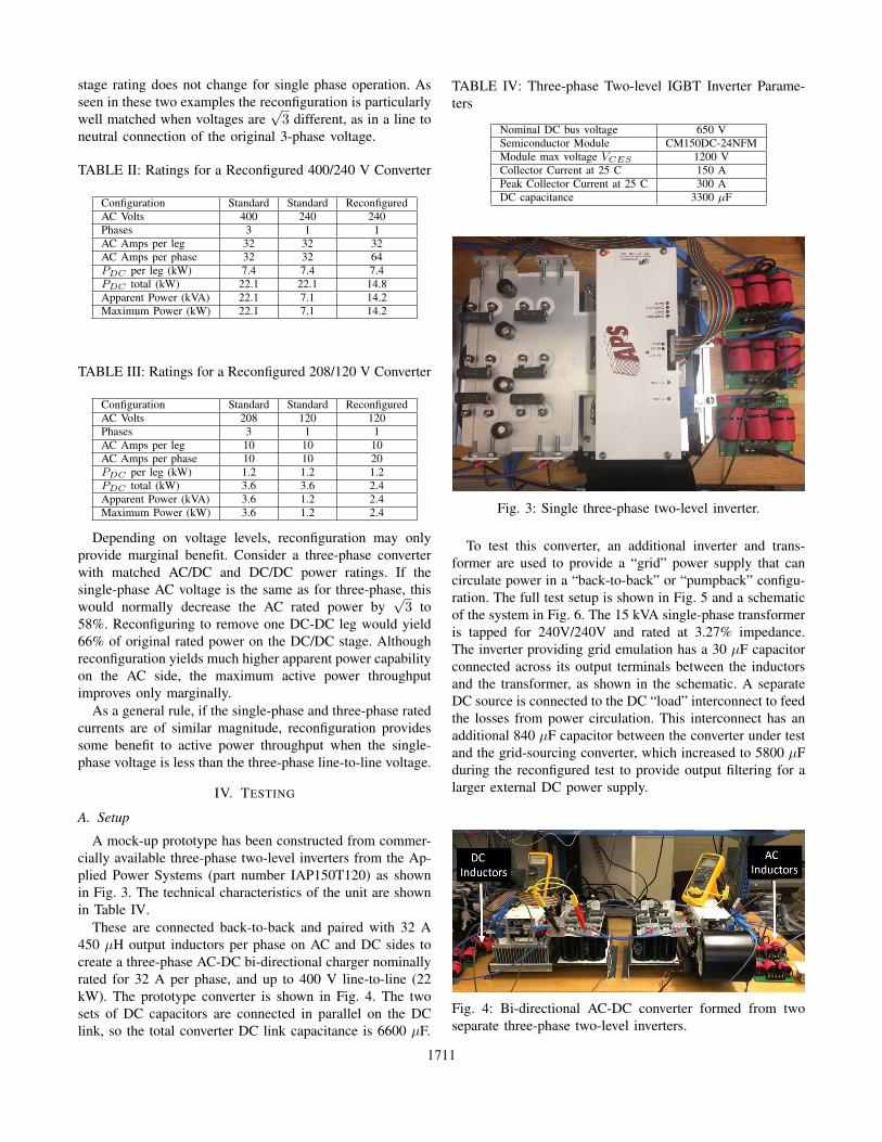
A mock-up prototype has been constructed from commer-
cially available three-phase two-level inverters from the Ap-
plied Power Systems (part number IAP150T120) as shown
in Fig. 3. The technical characteristics of the unit are shown
in Table IV.
These are connected back-to-back and paired with 32 A
450 μH output inductors per phase on AC and DC sides to
create a three-phase AC-DC bi-directional charger nominally
rated for 32 A per phase, and up to 400 V line-to-line (22
kW). The prototype converter is shown in Fig. 4. The two
sets of DC capacitors are connected in parallel on the DC
link, so the total converter DC link capacitance is 6600 μF.
TABLE IV: Three-phase Two-level IGBT Inverter Parame-
ters
Nominal DC bus voltage 650 VSemiconductor Module CM150DC-24NFMModule max voltage VCES 1200 VCollector Current at 25 C 150 APeak Collector Current at 25 C 300 ADC capacitance 3300 μF
Fig. 3: Single three-phase two-level inverter.
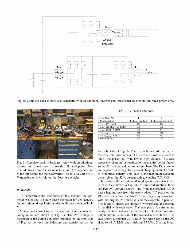
To test this converter, an additional inverter and trans-
former are used to provide a “grid” power supply that can
circulate power in a “back-to-back” or “pumpback” configu-
ration. The full test setup is shown in Fig. 5 and a schematic
of the system in Fig. 6. The 15 kVA single-phase transformer
is tapped for 240V/240V and rated at 3.27% impedance.
The inverter providing grid emulation has a 30 μF capacitor
connected across its output terminals between the inductors
and the transformer, as shown in the schematic. A separate
DC source is connected to the DC “load” interconnect to feed
the losses from power circulation. This interconnect has an
additional 840 μF capacitor between the converter under test
and the grid-sourcing converter, which increased to 5800 μF
during the reconfigured test to provide output filtering for a
larger external DC power supply.
Fig. 4: Bi-directional AC-DC converter formed from two
separate three-phase two-level inverters.
1711
DC
IAIA DC
IC DC
IB DC
VAB (cap)+
VAB+
AC GridEmulator
IA GS
Fig. 6: Complete back-to-back test schematic with an additional inverter and transformer to provide full rated power flow.
Fig. 5: Complete back-to-back test setup with an additional
inverter and transformer to provide full rated power flow.
The additional inverter, its inductors, and AC capacitor are
to the left behind the main converter. The 15 kVA 240 V/240
V transformer is visible on the floor to the right.
B. Results
To demonstrate the usefulness of this method, the con-
verter was tested in single-phase operation for the standard
and reconfigured topologies, under conditions shown in Table
V.
Voltage and current traces for test case 1 in the standard
configuration are shown in Fig. 7a. The AC voltage is
measured at the output converter terminals on the right side
of Fig. 1b, between the inductors and transformer on the
TABLE V: Test Conditions
Test Case No. 1 2Configuration 1-phase standard 1-phase reconfiguredVAC (V RMS) 240 240IAC per phase (A RMS) 32 32IAC Total (A RMS) 32 64VDClink (V) 435 435VDCoutput (V) 370 370Power (kVA) 7.7 15.4
far right side of Fig. 6. There is only one AC current in
this case, but three separate DC currents. Positive current is
“into” the phase leg, from low to high voltage. This case
represents charging or rectification near unity power factor,
so the AC voltage and current are in phase. The DC currents
are negative on average to represent charging on the DC side
to a nominal battery. This case is the maximum available
power given the 32 A current rating, yielding 7.68 kVA.
In contrast, the reconfigured single-phase variant is tested
in case 2 as shown in Fig. 7b. In this configuration, there
are two AC currents shown, one from the original AC A
phase leg, and one from the newly-added “A” phase on the
DC side. Switching for this DC phase leg is synchronized
with the original AC phase A, and they operate in parallel.
The B and C phases are similarly synchronized and operate
in parallel with each other. The two phase A currents are
nearly identical and overlap on the plot. The total converter
output current is the sum of the two and is also shown. This
case shows a nominal 32 A RMS per phase leg on the AC
side, so 64 A RMS total, yielding 15 kVA. Sharing is not
1712

0 5 10 15 20 25 30 35 40 45 50
Time(ms)
-500
0
500V
olta
ge (
V)
-150
-100
-50
0
50
100
150
Cur
rent
(A
)
Inverter AC voltages and currents
VAB
IA
0 5 10 15 20 25 30 35 40 45 50
Time(ms)
-60
-40
-20
0
20
40
60
Cur
rent
(A
)
DC-DC converter currents
IA-DC
IB-DC
IC-DC
(a) Standard single-phase operation at 240 Vac and 32 A RMS AC current,which provides 7.7 kVA. All three DC legs provide DC current, switchingat 10 kHz. Phase A and B AC current is provided by one phase leg each,switching at 5 kHz.
0 5 10 15 20 25 30 35 40 45 50
Time(ms)
-500
0
500
Vol
tage
(V
)
-150
-100
-50
0
50
100
150
Cur
rent
(A
)
Inverter AC voltages and currents
VAB
IA
(Inv)
IA-DC
IA
(Inv)+IA-DC
0 5 10 15 20 25 30 35 40 45 50
Time(ms)
-60
-40
-20
0
20
40
60
Cur
rent
(A
)
DC-DC converter currents
IB-DC
IC-DC
(b) Reconfigured single-phase operation at nominal 240 Vac and 64 A RMSfor 15 kVA. Each AC phase leg provides approximately 32 A RMS, andtwo operate in parallel to provide 64 A RMS total. In this case IA is 31.9A and IA−DC is 30.9 A for a total of 63 A. The DC-DC converter hasonly two channels as shown in the bottom plot. All bridges are switchingat 10 kHz.
Fig. 7: Standard and reconfigured single-phase use of a three-phase converter. The top plots show AC voltages and currents
during operation at 240 V in active rectification to provide DC load charging. The trace labels match Fig. 6.
perfect so the output current is 63 A RMS. Only two DC
currents are shown, as the third DC leg is providing AC
current.
Perhaps the most striking feature of Fig. 7 is the clear
transition of one DC phase leg to the AC side, where it
significantly augments the AC current. The multiple phase
legs share current effectively, particularly on the AC side.
The DC side current sharing in case 1 (Fig. 7a) shows legs
A and B matching well, but the only minor anomaly appears
to be the leg C DC current. The exact reason is unclear, but
after further inspection, the wiring on that output is slightly
different than the other two and may contribute to the issue.
For completeness, the voltage and current on the “grid”
side of the transformer, at the output of the inverter used for
power circulation are shown in Fig. 8 during case 2. A small
AC filter capacitor there ensures a smooth voltage waveform,
while the increased voltage ripple visible in the top of Fig.
7b is due to transformer impedance.
V. CONCLUSIONS
This reconfigurable inverter topology uses standard
bridges, switching technology, and two-stage AC/DC DC/DC
design, but allows a much wider range of application voltages
through a simple reconfiguration. It uses common parts for
both the inverter and DC-DC stages. Many inverters are
0 5 10 15 20 25 30 35 40 45 50
Time(ms)
-500
0
500
Vol
tage
(V
)
-100
-50
0
50
100
Cur
rent
(A
)
Grid source AC voltages and currents
VAB
(cap)
IA-GS
Fig. 8: Traces from the grid source converter
already constructed this way, so the practical impact could be
significant in that many existing designs could extend their
operating range with relatively minor adjustments. An appli-
cation example was provided for electric vehicle charging,
but many applications could benefit from this single- and
three-phase reconfiguration.
Testing demonstrated the effectiveness of the reconfigu-
ration in doubling the AC power output compared to the
standard single-phase case, and showed balanced current
sharing between parallel bridges.
1713

REFERENCES
[1] M. Yilmaz and P. T. Krein, “Review of battery charger topologies,charging power levels, and infrastructure for plug-in electric andhybrid vehicles,” IEEE Transactions on Power Electronics, vol. 28,no. 5, pp. 2151–2169, May 2013.
[2] F. Musavi, W. Eberle, and W. G. Dunford, “A high-performance single-phase bridgeless interleaved pfc converter for plug-in hybrid electricvehicle battery chargers,” IEEE Transactions on Industry Applications,vol. 47, no. 4, pp. 1833–1843, Jul. 2011.
[3] L. Shi, A. Meintz, and M. Ferdowsi, “Single-phase bidirectional AC-DC converters for plug-in hybrid electric vehicle applications,” inProc. IEEE Vehicle Power and Propulsion Conf, Sep. 2008, pp. 1–5.
[4] D. C. Erb, O. C. Onar, and A. Khaligh, “Bi-directional chargingtopologies for plug-in hybrid electric vehicles,” in Proc. Twenty-FifthAnnual IEEE Applied Power Electronics Conf. and Exposition (APEC),Feb. 2010, pp. 2066–2072.
[5] L. Solero, “Nonconventional on-board charger for electric vehiclepropulsion batteries,” IEEE Transactions on Vehicular Technology,vol. 50, no. 1, pp. 144–149, Jan. 2001.
[6] A. Kuperman, U. Levy, J. Goren, A. Zafransky, and A. Savernin,“Battery charger for electric vehicle traction battery switch station,”IEEE Transactions on Industrial Electronics, vol. 60, no. 12, pp. 5391–5399, Dec. 2013.
[7] N. Sakr, D. Sadarnac, and A. Gascher, “A review of on-board inte-grated chargers for electric vehicles,” in Power Electronics and Appli-cations (EPE’14-ECCE Europe), 2014 16th European Conference on.IEEE, 2014, pp. 1–10.
[8] Y. J. Lee, A. Khaligh, and A. Emadi, “Advanced integrated bidi-rectional AC/DC and DC/dc converter for plug-in hybrid electricvehicles,” IEEE Transactions on Vehicular Technology, vol. 58, no. 8,pp. 3970–3980, Oct. 2009.
[9] M. A. Khan, Bi-directional DC-DC and DC-AC Converter Systemsfor Vehicle-to-Grid and Grid-to-Vehicle Power Transfer in Plug-in-Electric Vehicles. North Carolina State University, 2015.
[10] W. Kempton and J. Tomic, “Vehicle-to-grid power implementation:From stabilizing the grid to supporting large-scale renewable energy,”Journal of power sources, vol. 144, no. 1, pp. 280–294, 2005.
[11] W. Kempton, J. Tomic, S. Letendre, A. Brooks, and T. Lipman,“Vehicle-to-grid power: battery, hybrid, and fuel cell vehicles asresources for distributed electric power in california,” Institute ofTransportation Studies, 2001.
[12] A. N. Brooks et al., Vehicle-to-grid demonstration project: Gridregulation ancillary service with a battery electric vehicle. CaliforniaEnvironmental Protection Agency, Air Resources Board, ResearchDivision, 2002.
[13] S. B. Peterson, J. Whitacre, and J. Apt, “The economics of using plug-in hybrid electric vehicle battery packs for grid storage,” Journal ofPower Sources, vol. 195, no. 8, pp. 2377–2384, 2010.
[14] X. Zhou, G. Wang, S. Lukic, S. Bhattacharya, and A. Huang, “Multi-function bi-directional battery charger for plug-in hybrid electricvehicle application,” in Proc. IEEE Energy Conversion Congress andExposition, Sep. 2009, pp. 3930–3936.
[15] C. Chang, A. Hernandez, and G. Bruning, “Reconfigurable con-verter for multiple-level input-line voltages,” Patent US 6 373 725 B1,Apr. 16, 2002.
[16] S. Zeljkovic, T. Reiter, and D. Gerling, “Single-stage reconfigurabledc/dc converter for wide input voltage range operation in (h) evs,”IEEJ Journal of Industry Applications, vol. 4, no. 4, pp. 424–433,2015.
[17] D. El-Damak, S. Bandyopadhyay, and A. P. Chandrakasan, “A 93%efficiency reconfigurable switched-capacitor dc-dc converter using on-chip ferroelectric capacitors,” in Solid-State Circuits Conference Digestof Technical Papers (ISSCC), 2013 IEEE International. IEEE, 2013,pp. 374–375.
[18] H.-P. Le, M. Seeman, S. R. Sanders, V. Sathe, S. Naffziger, andE. Alon, “A 32nm fully integrated reconfigurable switched-capacitordc-dc converter delivering 0.55 w/mm 2 at 81% efficiency,” in Solid-State Circuits Conference Digest of Technical Papers (ISSCC), 2010IEEE International. IEEE, 2010, pp. 210–211.
1714