Embed Size (px)
Citation preview
PSFC/JA-17-27
A Quench Detection Method for REBCO Conductor Operating in Gas or Liquid
Makoto Takayasu
June 22, 2017
Plasma Science and Fusion Center Massachusetts Institute of Technology
Cambridge, MA 02139
This work was partially supported by the U. S. Department of Energy, Office of Fusion Energy Science under Grant DE-FC02-93ER54186.
2
ABSTRACT
This memo describes a novel method to detect a quench and abnormal behavior of a superconducting conductor in a cable of a magnet using acoustic sensor technology. By monitoring continuously, the coolant condition of a superconducting conductor using acoustic sensors, a condition change ,such as a temperature rise, can be detected very quickly for superconducting power transmission cables and magnets. Acoustic sensors are installed along the coolant space of a superconducting conductor and monitor the coolant condition. By a disposition of the acoustic sensor array in a coolant flow channel, this method allows the acoustic sensor system to quickly detect a local condition with precise spatial resolution. This method is useful for superconducting conductor of a magnet and power cable made of a cable-in-conduit-conductor (CICC), and also it is especially useful for a high temperature superconducting (HTS) conductor, such as REBCO tape conductors.
KEYWORDS: Quench detection, acoustic sensor, superconducting magnet, cable-in-conduit-conductor (CICC), superconducting power cable, HTS, REBCO.
3
1. Introduction
Superconducting devices such as superconducting magnets and power transmission cables must be cooled below their critical operation temperature. In fact, only below the critical temperature, the conductors of the devices are superconductive. They are cooled with low temperature coolant gas or liquid such as helium, hydrogen, neon, and nitrogen, and others.
When the superconducting material is cooled, the normal resistive state becomes a
superconductive state, and the electric resistivity becomes zero. However, during operation a superconductor can abruptly change its state from superconductive to normal. When this event occurs it is called “quench.” When a quench occurs, it is important to discard the external applied electric power and safely dissipate the electromagnetic energy of the superconducting devices (magnet and/or power cable) into a protection circuit. In order safely discharge the devices, it is essential to detect the quench as fast as possible, otherwise the superconducting conductor may be seriously degraded or even burned out.
Recently high temperature superconductors (HTS) such as BSCCO and REBCO
conductors have been developed and they are commercially available. The devices made with those conductors are operated in liquid nitrogen, liquid helium, liquid hydrogen or helium gas. HTS conductor have excellent mechanical properties, as well as high current density at a high magnetic field. The HTS tapes will be very attractive for high field superconducting magnet applications such as various industrial magnet devices for compact synchrocyclotrons, MRI, NMR, SMES, transformers, fault current limiters and generators, fusion and accelerator magnets.
However, detecting a quench in HTS especially REBCO conductors is very difficult
since normal zone propagation velocities are very slow compared with other type of superconductors called low-temperature-superconductor (LTS) such as NbTi and Nb3Sn, and the quench zone is confined to a very small area. For those reasons, it is difficult to detect a quench of HTS devices using conventional electric voltage methods. To detect quickly a quench for a HTS devices it is essential to implement a very sensitive quench detection method.
Various quench detection methods have been developed: (1) Voltage detection of a
normal zone, (2) Hydraulic coolant pressure detection, (3) Detection of acoustic emission (AE) due to cracking, delamination and rapid temperature changes of a quench [1]-[8], and (4) temperature detection by optical fibers [9]. So far, the voltage detection method using voltage taps has been most commonly used. The voltage taps must be mounted (soldered) on a superconducting conductor and electric wires are co-wound along the conductor in order to cancel undesired induced inductive voltages. The electric wires used for voltage taps complicate the fabrication of a magnet and its operation due to high induced voltage. Therefore, it is not desirable to install many voltage tap wires on a magnet. Other quench detections are still under development, and their usage is very limited at present.
4
A possible and novel alternative to the most common voltage taps method is discussed in this document and consists in detecting a quench and magnet temperature changes using acoustic sensors in a coolant channel along a superconducting conductor. The acoustic sensors are small enough to be installed in a cooling channel, and they are arranged to form an array along the cooling channel. The acoustic sensor array detects an acoustic signal by externally connected electric devices such as electric amplifiers.
To determine a quench location, it is possible to identify the acoustic sensor that
generates the acoustic signals. Acoustic sensor generates an output voltage due to acoustic waves caused by temperature and mechanical hydraulic condition changes of the coolant in which the superconductor is immersed. When a quench occurs, superconductors generate heat that vaporizes liquid coolant or causes thermal coolant expansion. Those events generate acoustic wave to be detected with an acoustic sensor. Even smaller heat disturbance before quenching, such as nuclear heating condition of the coolant creates small bubble at the heating surface (magnet surface) and generate acoustic wave. The acoustic wave signals are detected by acoustic sensors to find abnormal condition of a superconducting device.
An acoustic sensor allows identifying the location of temperature changes in a
superconducting conductor. The detection sensors are distributed in a coolant channel, therefore it makes quick detection possible. Furthermore, it can be easily electrically isolated from a superconducting conductor avoiding problematic issues observed with other techniques (shorts of voltage taps). The acoustic sensor array is easily installed in a cooling channel. Even after fabrication, it can be inserted from one end of a superconducting conductor.
The proposed method is different from existing conventional Acoustic Emission
(AE) type quench detection techniques [1]-[8]. Conventional AE method detects a quench or mechanical movement (cracking or conductor motion) of a superconducting magnet and does not record the coolant behavior. AE sensors are mounted on a magnet surface, and the sensor detects acoustic wave due to mechanical movement such as cracking of epoxy on a superconducting conductor caused by thermal stress when a magnet is cooled and quenches, or by stress due to an electromagnetic force when a magnet is charged.
2. Method
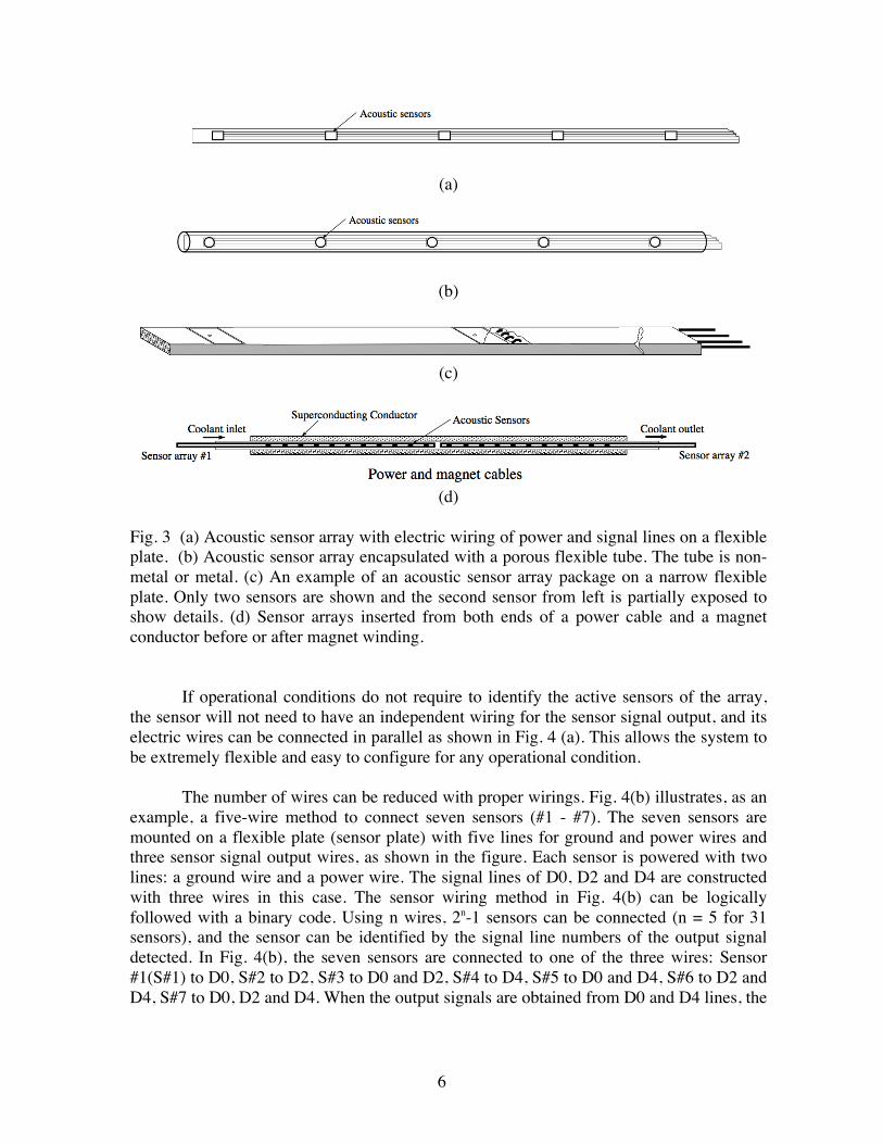
Fig. 1 shows conceptually an acoustic sensor array to detect an abnormality, such as a quench, of a superconducting magnet immersed in a coolant. The acoustic signals are received in the coolant by the sensors arranged in a linear array. The acoustic sensor array is composed of micro acoustic sensors (microphones) which are mounted in line on a narrow long flexible plate or a long flexible porous tube (Fig. 3(b)). The sensors are mounted to minimize hydraulic resistance to reduce noises due to hydraulic flow turbulence. Fig. 2 shows an example of commercially available capacitor-based acoustic sensors. The size is 3.8 mm x 3.0 mm x 1.1 mm. There are other types of acoustic sensor such a piezoelectric-type micro acoustic sensor. Sensors are to be operated in liquid and
5
vacuum environment, therefore acoustic sensors have different operational requirements from conventional commercial microphone type acoustic sensors. The sensor characteristics can be specific for each application to meet the required frequency responses.
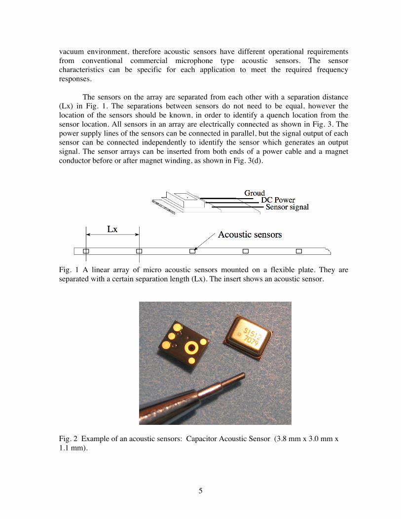
The sensors on the array are separated from each other with a separation distance
(Lx) in Fig. 1. The separations between sensors do not need to be equal, however the location of the sensors should be known, in order to identify a quench location from the sensor location. All sensors in an array are electrically connected as shown in Fig. 3. The power supply lines of the sensors can be connected in parallel, but the signal output of each sensor can be connected independently to identify the sensor which generates an output signal. The sensor arrays can be inserted from both ends of a power cable and a magnet conductor before or after magnet winding, as shown in Fig. 3(d).
Fig. 1 A linear array of micro acoustic sensors mounted on a flexible plate. They are separated with a certain separation length (Lx). The insert shows an acoustic sensor.
Fig. 2 Example of an acoustic sensors: Capacitor Acoustic Sensor (3.8 mm x 3.0 mm x 1.1 mm).
6
(a)
(b)
(c)
(d)
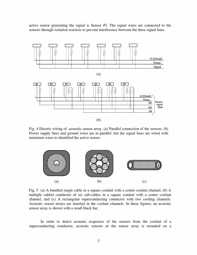
Fig. 3 (a) Acoustic sensor array with electric wiring of power and signal lines on a flexible plate. (b) Acoustic sensor array encapsulated with a porous flexible tube. The tube is non-metal or metal. (c) An example of an acoustic sensor array package on a narrow flexible plate. Only two sensors are shown and the second sensor from left is partially exposed to show details. (d) Sensor arrays inserted from both ends of a power cable and a magnet conductor before or after magnet winding.
If operational conditions do not require to identify the active sensors of the array,
the sensor will not need to have an independent wiring for the sensor signal output, and its electric wires can be connected in parallel as shown in Fig. 4 (a). This allows the system to be extremely flexible and easy to configure for any operational condition.
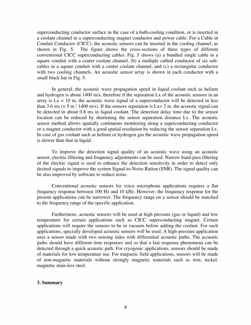
The number of wires can be reduced with proper wirings. Fig. 4(b) illustrates, as an
example, a five-wire method to connect seven sensors (#1 - #7). The seven sensors are mounted on a flexible plate (sensor plate) with five lines for ground and power wires and three sensor signal output wires, as shown in the figure. Each sensor is powered with two lines: a ground wire and a power wire. The signal lines of D0, D2 and D4 are constructed with three wires in this case. The sensor wiring method in Fig. 4(b) can be logically followed with a binary code. Using n wires, 2n-1 sensors can be connected (n = 5 for 31 sensors), and the sensor can be identified by the signal line numbers of the output signal detected. In Fig. 4(b), the seven sensors are connected to one of the three wires: Sensor #1(S#1) to D0, S#2 to D2, S#3 to D0 and D2, S#4 to D4, S#5 to D0 and D4, S#6 to D2 and D4, S#7 to D0, D2 and D4. When the output signals are obtained from D0 and D4 lines, the
7
active sensor generating the signal is Sensor #5. The signal wires are connected to the sensors through isolation resistors to prevent interference between the three signal lines.
(a)
(b)
Fig. 4 Electric wiring of acoustic sensor array. (a) Parallel connection of the sensors. (b) Power supply lines and ground wires are in parallel, but the signal lines are wired with minimum wires to identified the active sensor.
(a) (b) (c)
Fig. 5 (a) A bundled single cable in a square conduit with a center coolant channel, (b) A multiple cabled conductor of six sub-cables in a square conduit with a center coolant channel, and (c) A rectangular superconducting conductor with two cooling channels. Acoustic sensor arrays are inserted in the coolant channels. In these figures, an acoustic sensor array is shown with a small black bar.
In order to detect acoustic responses of the sensors from the coolant of a
superconducting conductor, acoustic sensors or the sensor array is mounted on a
8
superconducting conductor surface in the case of a bath-cooling condition, or is inserted in a coolant channel in a superconducting magnet conductor and power cable. For a Cable in Conduit Conductor (CICC), the acoustic sensors can be inserted in the cooling channel, as shown in Fig. 5. The figure shows the cross-sections of three types of different conventional CICC superconducting cables. Fig. 5 shows (a) a bundled single cable in a square conduit with a center coolant channel, (b) a multiple cabled conductor of six sub-cables in a square conduit with a center coolant channel, and (c) a rectangular conductor with two cooling channels. An acoustic sensor array is shown in each conductor with a small black bar in Fig. 5.
In general, the acoustic wave propagation speed in liquid coolant such as helium and hydrogen is about 1400 m/s, therefore if the separation Lx of the acoustic sensors in an array is Lx = 10 m, the acoustic wave signal of a superconductor will be detected in less than 3.6 ms (= 5 m / 1400 m/s). If the sensors separation is Lx= 2 m, the acoustic signal can be detected in about 0.8 ms in liquid coolant. The detection delay time due to the sensor location can be reduced by shortening the sensor separation distance Lx. The acoustic sensor method allows spatially continuous monitoring along a superconducting conductor or a magnet conductor with a good spatial resolution by reducing the sensor separation Lx. In case of gas coolant such as helium or hydrogen gas the acoustic wave propagation speed is slower than that in liquid.
To improve the detection signal quality of an acoustic wave using an acoustic
sensor, electric-filtering and frequency adjustments can be used. Narrow band-pass filtering of the electric signal is used to enhance the detection sensitivity in order to detect only desired signals to improve the system Signal-to-Noise Ration (SNR). The signal quality can be also improved by software to reduce noise.
Conventional acoustic sensors for voice microphone applications requires a flat
frequency response between 100 Hz and 10 kHz. However, the frequency response for the present applications can be narrower. The frequency range on a sensor should be matched to the frequency range of the specific application.
Furthermore, acoustic sensors will be used at high pressure (gas or liquid) and low
temperature for certain applications such as CICC superconducting magnet. Certain applications will require the sensors to be in vacuum before adding the coolant. For such applications, specially developed acoustic sensors will be used. A high-pressure application uses a sensor made with two sensing sides with differential acoustic paths. The acoustic paths should have different time responses and so that a fast response phenomena can be detected through a quick acoustic path. For cryogenic applications, sensors should be made of materials for low temperature use. For magnetic field applications, sensors will be made of non-magnetic materials without strongly magnetic materials such as iron, nickel, magnetic stain-less steel.
3. Summary
9
The proposed method allows the detection and diagnose of abrupt changes of a device operation condition through an acoustic sensor array in liquid or gas. The purpose is to detect a quench behavior quickly and determine the location of the incident.
Characteristics of the acoustic sensor method are: passive detection, very simple
voltage detection method, identification of location where the event occurs, economical, easy use. This method is also advantageous because it does not require external excitation such as laser-light and microwave, and there is no need to mount voltage taps on conductor.
This method is not limited to use for a superconducting conductor such as magnet, power transmission cable, SMES, MRI, motor and generator, but it could also be used for any electric devices in liquid or gas.
The acoustic sensor system continuously monitors with both spatial and temporal
high resolutions. Acoustic sensors are installed along a coolant space of a superconducting conductor and monitor coolant condition. The acoustic sensors can electrically detect temperature change or coolant flow disruption very quickly. The technique is used to detect a quench and to identify the location of a quench of a superconducting magnet, or a superconducting power cable. This method is very useful for superconducting conductor of a magnet and power cable made of a cable-in-conduit-conductor (CICC), and also it is especially useful for a high temperature superconducting (HTS) conductor, such as REBCO and BSCCO HTS tape conductors.
References [1] O. Tsukamoto, J. F. Maguire, E. S. Bobrov, and Y. Iwasa, “Identification of quench
origins in a superconductor with acoustic emission and voltage measurements,” Appl. Phys. Lett., vol. 39, pp. 172–174, 1981.
[2] O. Tsukamoto and Y. Iwasa, “Sources of acoustic emission in superconducting
magnets,” J. Appl. Phys., vol. 54, pp. 997–1007, 1983. [3] T. Ishigohka, O. Tsukamoto, and Y. Iwasa, “Method to detect a temperature rise in
superconducting coils with piezoelectric sensors,” Appl. Phys. Lett., vol. 43, pp. 317–318, 1983.
[4] O. Tsukamoto and Y. Iwasa, “Correlation of acoustic emission with normal zone
occurrence in epoxy-impregnated windings: an application of acoustic emission diagnostic technique to pulse superconducting magnets,” Appl. Phys. Lett., vol. 44, pp. 922–924, 1984.
[5] Peter J. de Groot, Peter A. M. Wijnen & Roger B. F. Janssen, “Real-time frequency
determination of acoustic emission for different fracture mechanisms in carbon/epoxy composites,” Composites Science and Technology, 1995, 55, 405 – 412.
10
[6] Y. Iwasa, “HTS magnets: stability; protection; cryogenics; economics; current stability/protection activities at FBML,” Cryogenics, vol. 43, pp. 303–316, 2003.
[7] M. Yoneda, N. Nanato, D. Aoki, T. Kato, S. Murase, “Quench detection/protection of
an HTS coil by AE signals,” Physica C; 2011. [8] N. Nanato. “Detection of temperature rise in YBCO coil by time--frequency
visualization of AE signals of AE signals,” Physica C; 2009, 469, pp. 1808-1810. [9] W K Chan1, G Flanagan2 and J Schwartz1, “Spatial and temporal resolution
requirements for quench detection in (RE)Ba2Cu3Ox magnets using Rayleigh-scattering-based fiber optic distributed sensing,” Supercond. Sci. Technol. 26 (2013) 105015 (12pp).