Embed Size (px)
Citation preview
superior performance. powerful technology.
SuperPower Inc. is a subsidiary of Furukawa Electric Co. Ltd.
Delamination behavior study of REBCO
coated conductor wires fabricated by
MOCVD on IBAD-MgO template Yifei Zhang, A. Knoll, A. Sundaram, D.W. Hazelton, R.B. McClure, and H. Sakamoto
2014 Applied Superconductivity Conference
August 10-15, 2014, Charlotte, NC, USA
2014 ASC Charlotte, NC Aug. 14, 2014 4MOr2A All Rights Reserved. Copyright SuperPower® Inc. 2014
Outline
• Delamination in coated conductor wire
• Performance of dry-wound and wet-wound coils
• Delamination behavior study using pin-pull test and anvil test
− Weibull analysis of test results
• Delamination behavior study using peel test
− Effect of peeling angle
− Peeling location
• Summary
2
2014 ASC Charlotte, NC Aug. 14, 2014 4MOr2A All Rights Reserved. Copyright SuperPower® Inc. 2014
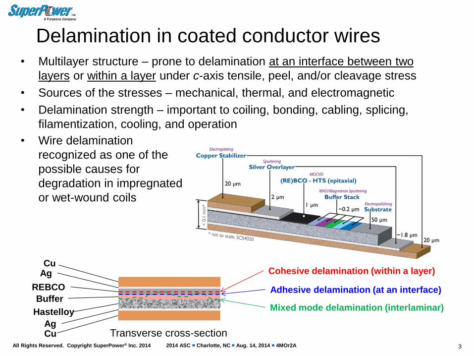
Delamination in coated conductor wires • Multilayer structure – prone to delamination at an interface between two
layers or within a layer under c-axis tensile, peel, and/or cleavage stress
• Sources of the stresses – mechanical, thermal, and electromagnetic
• Delamination strength – important to coiling, bonding, cabling, splicing,
filamentization, cooling, and operation
3
Cu
REBCO
Buffer
Hastelloy
Cu
Cohesive delamination (within a layer)
Adhesive delamination (at an interface)
Mixed mode delamination (interlaminar)
Ag
Ag Transverse cross-section
• Wire delamination
recognized as one of the
possible causes for
degradation in impregnated
or wet-wound coils
2014 ASC Charlotte, NC Aug. 14, 2014 4MOr2A All Rights Reserved. Copyright SuperPower® Inc. 2014
Degradation of wet-wound coil – an example
4
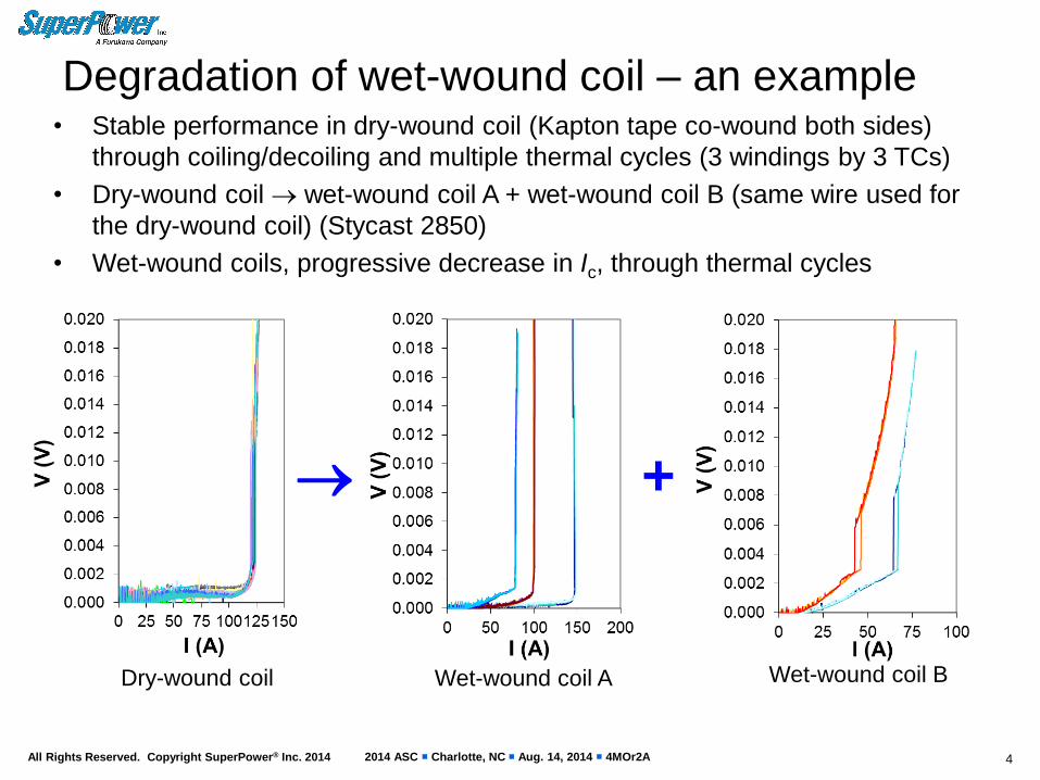
• Stable performance in dry-wound coil (Kapton tape co-wound both sides)
through coiling/decoiling and multiple thermal cycles (3 windings by 3 TCs)
• Dry-wound coil wet-wound coil A + wet-wound coil B (same wire used for
the dry-wound coil) (Stycast 2850)
• Wet-wound coils, progressive decrease in Ic, through thermal cycles
Dry-wound coil Wet-wound coil A Wet-wound coil B
+
2014 ASC Charlotte, NC Aug. 14, 2014 4MOr2A All Rights Reserved. Copyright SuperPower® Inc. 2014
Failure analysis of degraded wet-wound coil
5
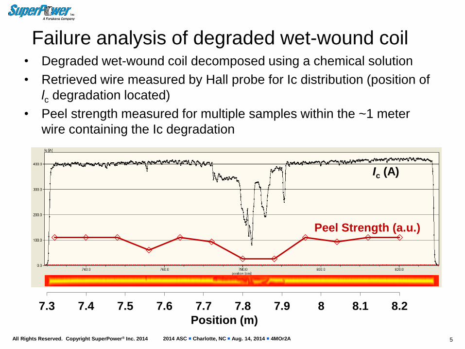
• Degraded wet-wound coil decomposed using a chemical solution
• Retrieved wire measured by Hall probe for Ic distribution (position of
lc degradation located)
• Peel strength measured for multiple samples within the ~1 meter
wire containing the Ic degradation
Ic (A)
Position (m)
7.3 7.4 7.5 7.6 7.7 7.8 7.9 8 8.1 8.2
Peel Strength (a.u.)
2014 ASC Charlotte, NC Aug. 14, 2014 4MOr2A All Rights Reserved. Copyright SuperPower® Inc. 2014
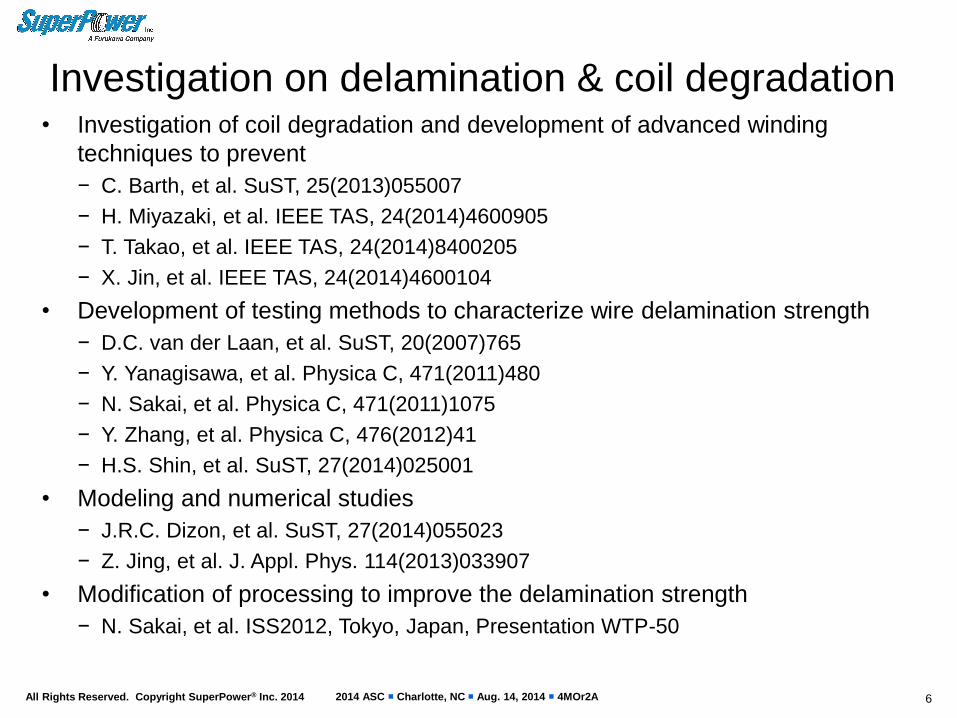
Investigation on delamination & coil degradation
6
• Investigation of coil degradation and development of advanced winding
techniques to prevent
− C. Barth, et al. SuST, 25(2013)055007
− H. Miyazaki, et al. IEEE TAS, 24(2014)4600905
− T. Takao, et al. IEEE TAS, 24(2014)8400205
− X. Jin, et al. IEEE TAS, 24(2014)4600104
• Development of testing methods to characterize wire delamination strength
− D.C. van der Laan, et al. SuST, 20(2007)765
− Y. Yanagisawa, et al. Physica C, 471(2011)480
− N. Sakai, et al. Physica C, 471(2011)1075
− Y. Zhang, et al. Physica C, 476(2012)41
− H.S. Shin, et al. SuST, 27(2014)025001
• Modeling and numerical studies
− J.R.C. Dizon, et al. SuST, 27(2014)055023
− Z. Jing, et al. J. Appl. Phys. 114(2013)033907
• Modification of processing to improve the delamination strength
− N. Sakai, et al. ISS2012, Tokyo, Japan, Presentation WTP-50
2014 ASC Charlotte, NC Aug. 14, 2014 4MOr2A All Rights Reserved. Copyright SuperPower® Inc. 2014 7
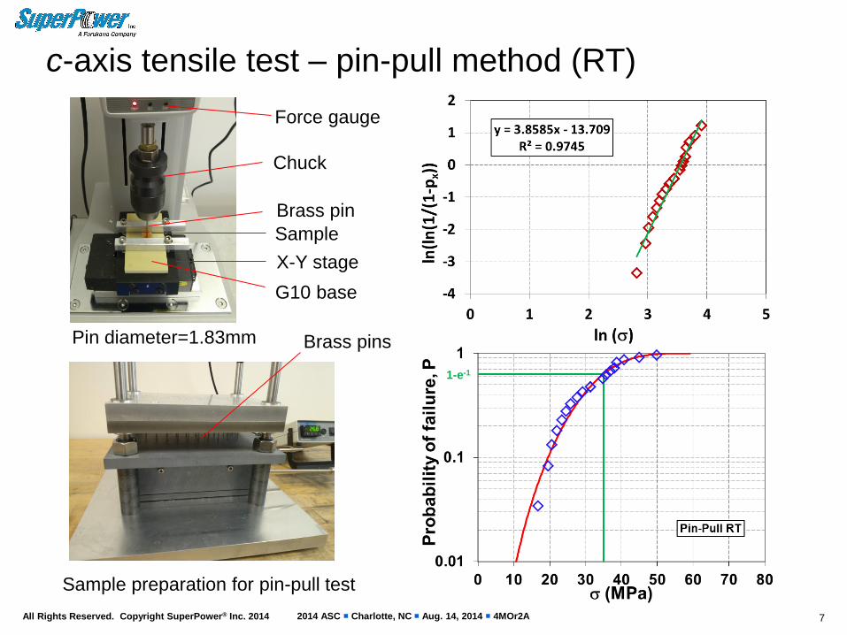
c-axis tensile test – pin-pull method (RT)
Chuck
Brass pin
Sample
X-Y stage
Force gauge
G10 base
Pin diameter=1.83mm
Sample preparation for pin-pull test
Brass pins
1-e-1
2014 ASC Charlotte, NC Aug. 14, 2014 4MOr2A All Rights Reserved. Copyright SuperPower® Inc. 2014
1-e-1
8
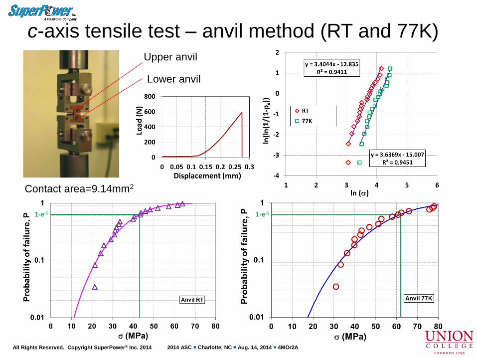
c-axis tensile test – anvil method (RT and 77K) Upper anvil
Lower anvil
Contact area=9.14mm2
1-e-1
2014 ASC Charlotte, NC Aug. 14, 2014 4MOr2A All Rights Reserved. Copyright SuperPower® Inc. 2014 9
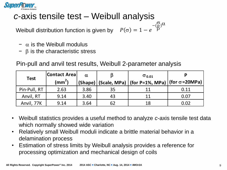
c-axis tensile test – Weibull analysis
• Weibull statistics provides a useful method to analyze c-axis tensile test data
which normally showed wide variation
• Relatively small Weibull moduli indicate a brittle material behavior in a
delamination process
• Estimation of stress limits by Weibull analysis provides a reference for
processing optimization and mechanical design of coils
𝑃 = 1 − 𝑒−()
Weibull distribution function is given by
− is the Weibull modulus
− is the characteristic stress
Pin-pull and anvil test results, Weibull 2-parameter analysis
TestContact Area
(mm2)
(Shape)
(Scale, MPa)
0.01
(for P=1%, MPa)
P
(for =20MPa)
Pin-Pull, RT 2.63 3.86 35 11 0.11
Anvil, RT 9.14 3.40 43 11 0.07
Anvil, 77K 9.14 3.64 62 18 0.02
2014 ASC Charlotte, NC Aug. 14, 2014 4MOr2A All Rights Reserved. Copyright SuperPower® Inc. 2014
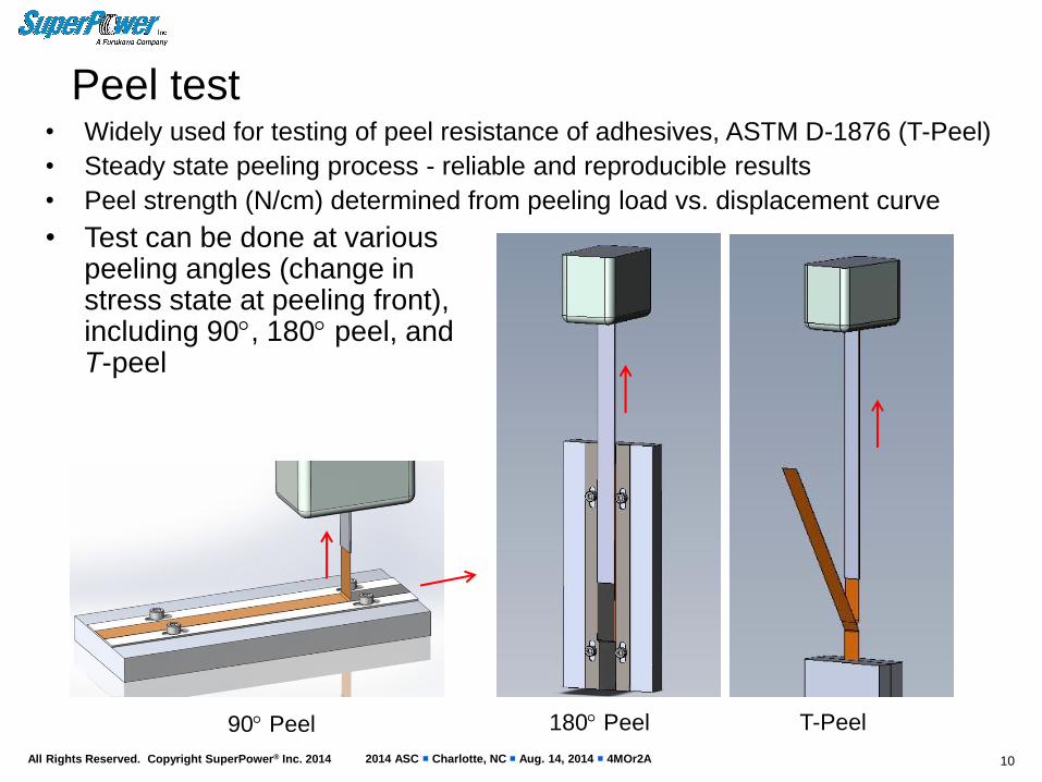
Peel test
10
90 Peel 180 Peel T-Peel
• Widely used for testing of peel resistance of adhesives, ASTM D-1876 (T-Peel)
• Steady state peeling process - reliable and reproducible results
• Peel strength (N/cm) determined from peeling load vs. displacement curve
• Test can be done at various peeling angles (change in stress state at peeling front), including 90, 180 peel, and T-peel
2014 ASC Charlotte, NC Aug. 14, 2014 4MOr2A All Rights Reserved. Copyright SuperPower® Inc. 2014
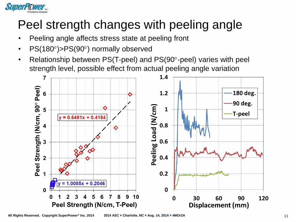
Peel strength changes with peeling angle • Peeling angle affects stress state at peeling front
• PS(180)>PS(90) normally observed
• Relationship between PS(T-peel) and PS(90-peel) varies with peel
strength level, possible effect from actual peeling angle variation
11
2014 ASC Charlotte, NC Aug. 14, 2014 4MOr2A All Rights Reserved. Copyright SuperPower® Inc. 2014
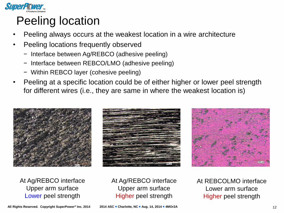
• Peeling always occurs at the weakest location in a wire architecture
• Peeling locations frequently observed
− Interface between Ag/REBCO (adhesive peeling)
− Interface between REBCO/LMO (adhesive peeling)
− Within REBCO layer (cohesive peeling)
• Peeling at a specific location could be of either higher or lower peel strength
for different wires (i.e., they are same in where the weakest location is)
12
Peeling location
At REBCOLMO interface
Lower arm surface
Higher peel strength
At Ag/REBCO interface
Upper arm surface
Higher peel strength
At Ag/REBCO interface
Upper arm surface
Lower peel strength

2014 ASC Charlotte, NC Aug. 14, 2014 4MOr2A All Rights Reserved. Copyright SuperPower® Inc. 2014
Peeling location – cont. • Peeling location depends on relative mechanical strengths of interfaces and
component layers, which are affected by conductor design and processing
• Most frequently observed peeling location is within REBCO layer (cohesive
peeling)
13
Peeled surface
Lower arm
OM image
Peeled surface
Upper arm
OM image
Peeling within REBCO
Schematic
REBCO
2014 ASC Charlotte, NC Aug. 14, 2014 4MOr2A All Rights Reserved. Copyright SuperPower® Inc. 2014
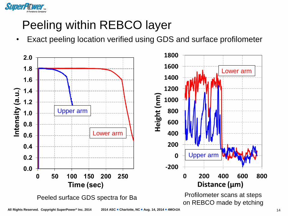
Peeling within REBCO layer
14
Upper arm
Lower arm
Peeled surface GDS spectra for Ba Profilometer scans at steps
on REBCO made by etching
Upper arm
Lower arm
• Exact peeling location verified using GDS and surface profilometer
2014 ASC Charlotte, NC Aug. 14, 2014 4MOr2A All Rights Reserved. Copyright SuperPower® Inc. 2014
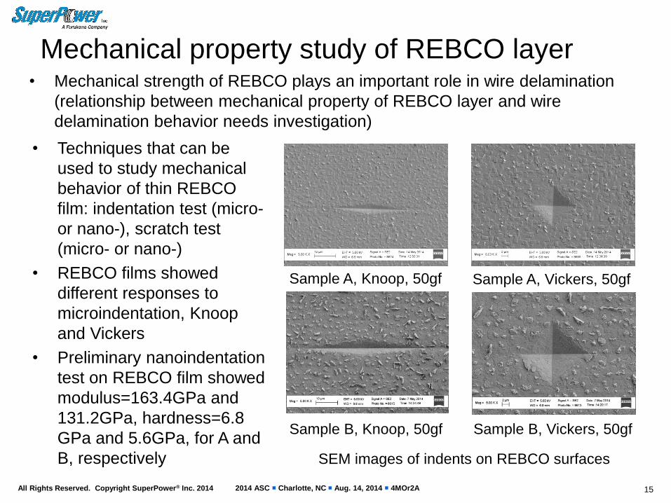
Mechanical property study of REBCO layer • Mechanical strength of REBCO plays an important role in wire delamination
(relationship between mechanical property of REBCO layer and wire
delamination behavior needs investigation)
15
Sample A, Knoop, 50gf
Sample B, Knoop, 50gf
Sample A, Vickers, 50gf
Sample B, Vickers, 50gf
• Techniques that can be
used to study mechanical
behavior of thin REBCO
film: indentation test (micro-
or nano-), scratch test
(micro- or nano-)
• REBCO films showed
different responses to
microindentation, Knoop
and Vickers
• Preliminary nanoindentation
test on REBCO film showed
modulus=163.4GPa and
131.2GPa, hardness=6.8
GPa and 5.6GPa, for A and
B, respectively SEM images of indents on REBCO surfaces
2014 ASC Charlotte, NC Aug. 14, 2014 4MOr2A All Rights Reserved. Copyright SuperPower® Inc. 2014
Summary
16
• HTS coated conductor wire delamination is investigated using pin-pull test,
anvil test, and peel test in combination with various microscopic analysis
techniques
• Measurement results from both pin-pull test and anvil test can be well
described with Weibull distribution
• Weibull analysis based on the result from anvil test at 77K indicated the c-axis
tensile strength (0.01) is about 18 MPa
• Peel test, featuring a steady state peeling process, is a useful method to study
delamination
• In peel tests, the most frequently observed peeling location is within REBCO
layer. Further investigation on mechanical property of REBCO film is needed
• “Degradation-free” coils can be made using coated conductor wires with
advanced winding techniques
2014 ASC Charlotte, NC Aug. 14, 2014 4MOr2A All Rights Reserved. Copyright SuperPower® Inc. 2014
Thank you for your attention!
17
For more information: http://www.superpower-inc.com
For questions: [email protected]