Embed Size (px)
Citation preview
A Prototype PET Scanner with DOI-EncodingDetectors
Yongfeng Yang1, Yibao Wu1, Jinyi Qi1, Sara St. James1, Huini Du1, Purushottam A. Dokhale2, Kanai S. Shah2,Richard Farrell2, and Simon R. Cherry1
1Department of Biomedical Engineering, University of California-Davis, Davis, California; and 2Radiation Monitoring Devices Inc.,Watertown, Massachusetts
Detectors with depth-encoding allow a PET scanner to simulta-neously achieve high sensitivity and high spatial resolution.Methods: A prototype PET scanner, consisting of depth-encodingdetectors constructed by dual-ended readout of lutetiumoxyorthosilicate (LSO) arrays with 2 position-sensitive avalanchephotodiodes (PSAPDs), was developed. The scanner comprised2 detector plates, each with 4 detector modules, and the LSOarrays consisted of 7 · 7 elements, with a crystal size of 0.9225 ·0.9225 · 20 mm and a pitch of 1.0 mm. The active area ofthe PSAPDs was 8 · 8 mm. The performance of individual detec-tor modules was characterized. A line-source phantom and ahot-rod phantom were imaged on the prototype scanner in 2 dif-ferent scanner configurations. The images were reconstructedusing 20, 10, 5, 2, and 1 depth-of-interaction (DOI) bins to dem-onstrate the effects of DOI resolution on reconstructed imageresolution and visual image quality. Results: The flood histo-grams measured from the sum of both PSAPD signals wereonly weakly depth-dependent, and excellent crystal identifica-tion was obtained at all depths. The flood histograms improvedas the detector temperature decreased. DOI resolution andenergy resolution improved significantly as the temperaturedecreased from 20�C to 10�C but improved only slightly with asubsequent temperature decrease to 0�C. A full width at halfmaximum (FWHM) DOI resolution of 2 mm and an FWHM energyresolution of 15% were obtained at a temperature of 10�C. Phan-tom studies showed that DOI measurements significantly im-proved the reconstructed image resolution. In the first scannerconfiguration (parallel detector planes), the image resolution atthe center of the field of view was 0.9-mm FWHM with 20 DOIbins and 1.6-mm FWHM with 1 DOI bin. In the second scannerconfiguration (detector planes at a 40� angle), the image resolu-tion at the center of the field of view was 1.0-mm FWHM with 20DOI bins and was not measurable when using only 1 bin. Con-clusion: PET scanners based on this detector design offer theprospect of high and uniform spatial resolution (crystal size,;1 mm; DOI resolution, ;2 mm), high sensitivity (20-mm-thickdetectors), and compact size (DOI encoding permits detectorsto be tightly packed around the subject and minimizes numberof detectors needed).
Key Words: small-animal PET; depth of interaction; position-sensitive avalanche photodiode; instrumentation
J Nucl Med 2008; 49:1132–1140DOI: 10.2967/jnumed.107.049791
Over the past decade, many small-animal PET scan-ners have been developed (1–12), and this technology hasplayed a very important role in the rapidly growing field ofmolecular imaging. High sensitivity is needed to increasesignal-to-noise ratio of the images to reliably detect lowerlevels of radiotracer uptake and to reduce the injected dose(reducing radiation dose to the subject) (13) and scan time(increasing temporal resolution for dynamic studies). Highspatial resolution is required to detect small structures andlesions and to improve quantification by reducing the partial-volume effect. A compromise between sensitivity and spatialresolution due to depth-of-interaction (DOI) effects alwaysexists in small-animal PET scanner design. Most designsuse a large detector ring radius (relative to the subject to bestudied) or a short crystal length to reduce the DOI effectsto acceptable levels. But in both cases, the sensitivity of thescanner is sacrificed.
Much attention in recent years has focused on detectordesigns with depth-encoding ability. Multilayer detectorsconsisting of crystal layers with different scintillation lightdecay times (14–16), comprising different reflector arrange-ments (17,18), and using a position shift of half a crystal fordifferent layers (19) have been proposed and successfullyimplemented to measure DOI. The DOI resolution obtainedby these methods is limited by the number of layers thatcan be decoded and is typically 5–10 mm. To eliminate theDOI effect completely, the DOI resolution needs to be aboutthe width of the detector itself. For small-animal PET, thedetector widths are typically 0.5–2 mm (8,10,20,21). There-fore, although these designs help reduce DOI-related deg-radation of spatial resolution, they are still not good enoughto allow detectors to be placed close to the subject. Thus,the classic trade-off between resolution and sensitivityremains, with scanners using thinner detectors and largerring diameters than wanted. The larger ring diameter also
Received Dec. 11, 2007; revision accepted Feb. 28, 2008.For correspondence or reprints contact: Yongfeng Yang, Department of
Biomedical Engineering, University of California-Davis, 451 E. Health SciencesDr., Davis, CA 95616.
E-mail: [email protected] ª 2008 by the Society of Nuclear Medicine, Inc.
1132 THE JOURNAL OF NUCLEAR MEDICINE • Vol. 49 • No. 7 • July 2008
by on January 13, 2020. For personal use only. jnm.snmjournals.org Downloaded from
has the undesirable effect of increasing the cost per unitsensitivity.
It is therefore important to develop detectors for small-animal PET with DOI resolution that approaches thedetector width. A promising approach for obtaining higherDOI resolution is to read out the scintillation light byplacing photodetectors at both ends of the crystal array anduse the ratio of the 2 photodetector signals to measure theDOI (22–26). An alternative approach being used to esti-mate DOI for monolithic scintillator crystals measures thedistribution of the scintillation light signal on a position-sensitive photodetector array (27,28). In this case, eventsoccurring nearer the photodetector produce a narrowerspread of scintillation light on the detectors than eventsoccurring farther from the photodetector, thus providing afoundation for discriminating on the basis of depth. Both ofthese approaches provide continuous DOI measurementrather than the discrete DOI information supplied by thelayered approach described earlier.
Our approach is to measure DOI by using a dual-endedreadout of finely pixelated lutetium oxyorthosilicate (LSO)arrays with 2 position-sensitive avalanche photodiodes(PSAPDs) (29–31). Our previous results on individual de-tector modules have shown that with such a detector atroom temperature, crystals arrays as small as 1 mm couldbe resolved and that an energy resolution of about 15% fullwidth at half maximum (FWHM) and a uniform DOIresolution of 3- to 4-mm FWHM (including the radiationbeam width of more than 2 mm) could be achieved (32). In
this work, the imaging performance of a prototype PETscanner consisting of 8 detector modules arranged in 2detector plates is evaluated. First, results obtained fromindividual detectors used within the scanner, includingmeasurements of the flood histograms calculated by usingthe energy signals from just 1 PSAPD or both PSAPDs, theperformance of the detectors at different temperatures, DOIresolution measured with a smaller radiation beam widthof 0.7 mm, and the timing resolution of the PSAPD, arepresented. Second, imaging studies are performed with theprototype scanner to measure the effect of the DOI infor-mation on reconstructed image resolution.
MATERIALS AND METHODS
The Prototype PET ScannerA schematic view of the prototype PET scanner is shown in
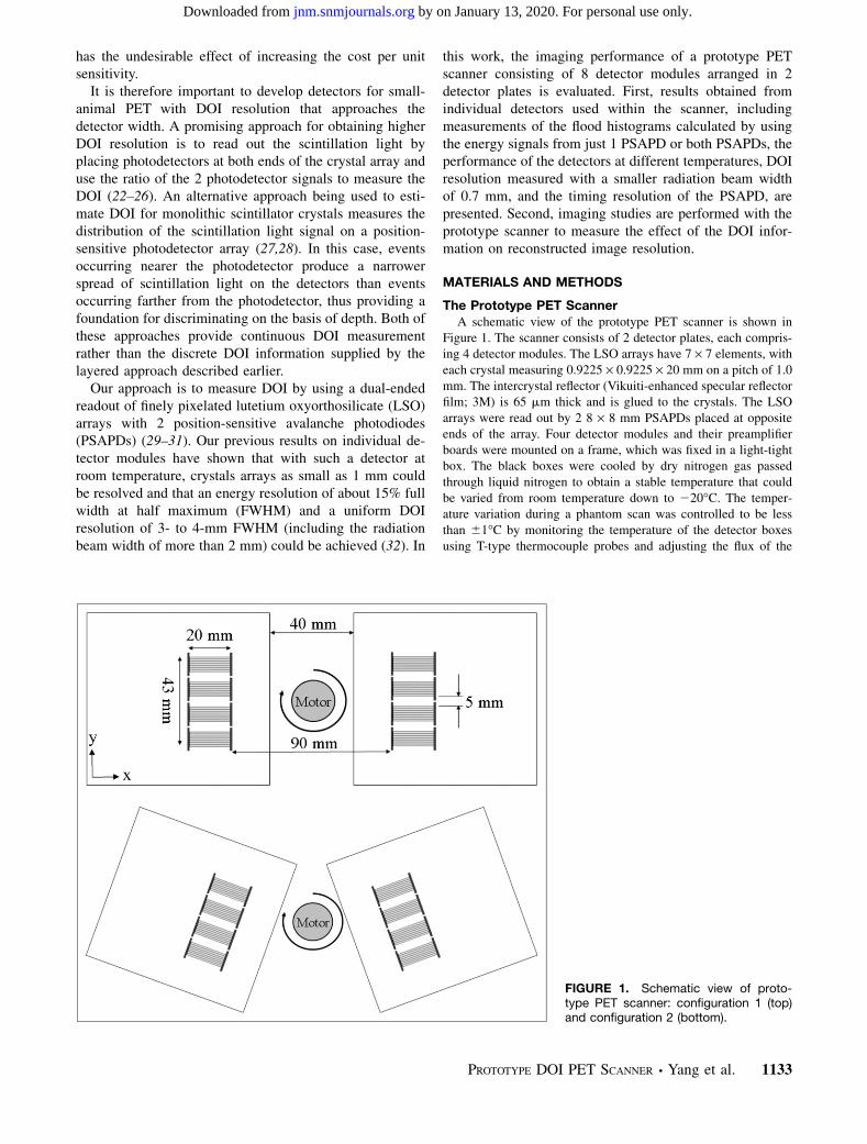
Figure 1. The scanner consists of 2 detector plates, each compris-ing 4 detector modules. The LSO arrays have 7 · 7 elements, witheach crystal measuring 0.9225 · 0.9225 · 20 mm on a pitch of 1.0mm. The intercrystal reflector (Vikuiti-enhanced specular reflectorfilm; 3M) is 65 mm thick and is glued to the crystals. The LSOarrays were read out by 2 8 · 8 mm PSAPDs placed at oppositeends of the array. Four detector modules and their preamplifierboards were mounted on a frame, which was fixed in a light-tightbox. The black boxes were cooled by dry nitrogen gas passedthrough liquid nitrogen to obtain a stable temperature that couldbe varied from room temperature down to 220�C. The temper-ature variation during a phantom scan was controlled to be lessthan 61�C by monitoring the temperature of the detector boxesusing T-type thermocouple probes and adjusting the flux of the
FIGURE 1. Schematic view of proto-type PET scanner: configuration 1 (top)and configuration 2 (bottom).
PROTOTYPE DOI PET SCANNER • Yang et al. 1133
by on January 13, 2020. For personal use only. jnm.snmjournals.org Downloaded from
nitrogen gas. Preamplifier boards were designed for the PSAPDsand used a preamplifier (CR-110; Cremat Inc.). Commerciallyavailable timing filter amplifiers, constant-fraction discriminators,coincidence modules, and spectroscopy amplifiers were used forthis scanner. Multiplexer boards were designed to reduce thenumber of energy signals coming from each detector plate from32 to 8 (33). Finally, the 16 position-encoding energy signals thatdefine an event (4 signals per PSAPD, 2 PSAPDs per detectormodule, 2 detector modules per coincidence) along with digitalsignals encoding the coincidence detector pair identification werestored in the list-mode data using a data-acquisition systemdeveloped in our laboratory (34). For tomographic imagingstudies, the 2 detector plates were held stationary and projectiondata were obtained by rotating the object (phantom) with astepping motor (model M061-LS-579, Superior Electric).
Individual Detector Module MeasurementsA single-detector module was mounted in the scanner black
box and measured with the setup previously published (Fig. 1 inthe article by Yang et al. (32)). In singles mode, the detectormodule was uniformly radiated from 1 side by a 0.5-mm-diameterpoint 22Na source; in coincidence mode, 1 depth of the array wasselectively radiated by electronic collimation with an LSO slabdetector measuring 16 · 16 · 2 mm. The slab detector was readout with a photomultiplier tube (PMT) (R590; Hamamatsu). Themeasurements were performed at temperatures of 0�C, 10�C, and20�C with both a distance from the point source to the slabdetector and a distance from the source to the LSO array of 5 cm.On the basis of the geometry, the radiation beam width on thearray was 2 mm. The temperature was measured in a locationclose to PSAPD 2. To minimize the contribution of the radiationbeam width to the DOI resolution, the measurements at 10�C werealso performed with the distance from the point source to the slabdetector measuring about 4 times that of the distance from thesource to the LSO array. The radiation beam width estimated fromthe geometry was 0.7 mm in those measurements. This geometrywas not used for all measurements, as data collection takes a longtime for the more constrained geometry and only 3 rows of thecrystals were irradiated. In all cases, coincidence measurementswere performed at 5 irradiation depths of 2, 6, 10, 14, and 18 mmmeasured from the location of PSAPD 1.
Flood Histograms and Energy ResolutionThe x- and y-coordinates of the flood histograms for PSAPD
1 and PSAPD 2 and the combination of the signal from bothPSAPDs were calculated using the position-encoding energysignals of the 2 PSAPDs and the following equations:
x1 5 ðB1 1 C1Þ=E1 y1 5 ðC1 1 D1Þ=E1
x2 5 ðB2 1 C2Þ=E2 y2 5 ðC2 1 D2Þ=E2
x112 5 ðx1 1 x2Þ=2 y112 5 ðy1 1 y2Þ=2
Here A1, B1, C1, and D1 are the 4 position-encoding energysignals from PSAPD 1, and A2, B2, C2, and D2 are the 4 position-encoding energy signals from PSAPD 2. The origin of the PSAPDcoordinate system was defined as the A corner. The B and Ccorners of the PSAPDs were defined as the positive x-direction,and the C and D corners were defined as the positive y-direction.
E1 and E2 are the total energy measured by PSAPD 1 and PSAPD2, respectively, and are calculated from the following equations:
E1 5 A1 1 B1 1 C1 1 D1
E2 5 A2 1 B2 1 C2 1 D2
For dual-ended readout, the total detected energy (Etotal) was takento be the sum of the energy measured by the 2 PSAPDs (Etotal 5
k · E11 E2). k is a gain-matching parameter. For each detectormodule, k is adjusted such that the DOI response of the wholearray is centered at a DOI ratio (E2/Etotal) of 0.5. Crystal look-uptables were created from the flood histograms calculated from thecombination of the 2 PSAPD signals and used to obtain the energyspectrum (Etotal) for each individual crystal. The FWHM energyresolution of the 511-keV photopeak was calculated by usinggaussian fitting.
DOI ResolutionThe parameter E2/Etotal was used to represent the DOI. Histo-
grams of the values of this ratio for individual crystals and for allcrystals in an array were obtained from the coincidence measure-ments performed at each irradiation depth. The FWHM DOIresolution was calculated by using a gaussian fitting of the DOIhistograms. The FWHM DOI resolution was then calibrated tounits of millimeters by using the relationship between the peak ofthe measured DOI ratio and the known irradiation depth informa-tion (32).
Timing ResolutionThe timing resolution of the dual-ended readout detector module
and the LSO slab detector was also measured at 5 irradiationdepths of 2, 6, 10, 14, and 18 mm. The LSO array was a 5 ·5 unpolished array with a crystal size of 1.5 · 1.5 · 20 mm.Standard nuclear instrumentation module electronics were used forthe timing-resolution measurements (23,35). The timing signal (thedifference of the single PMT timing and the summed timing signalobtained from the 2 PSAPDs) was stored in list mode together withthe position-encoding energy signals of the PSAPDs. By applying acrystal look-up table and individual crystal low-energy thresholds(350 keV), the timing spectra of individual crystals at each irradi-ation depth were obtained. The FWHM timing resolution wascalculated by gaussian fitting of the timing distribution.
Phantom ImagingA line-source phantom and a hot-rod phantom (Ultra-Micro
Hot Spot Phantom; Data Spectrum Corp.) were imaged on theprototype scanner in 2 different scanner configurations. In the firstconfiguration, the 2 detector plates were opposite and parallel toeach other as shown in Figure 1 (top). In the second configuration(Fig. 1, bottom), 1 detector plate was rotated clockwise by 20� andthe other one was rotated counterclockwise by 20� to simulateoblique angles of incidence that would be seen in a complete ringscanner. The geometric center of the 4 detector modules was fixedduring the detector plate rotations. The line-source phantomconsisted of 3 needles (100-mm inner diameter; 200-mm outsidediameter; 50-mm length). The radial offsets of the 3 needles were0, 7.5, and 15 mm. The hot-rod diameters were 0.75, 1.0, 1.35,1.70, 2.0, and 2.4 mm, with a rod-to-rod distance of twice the roddiameter. The phantoms were rotated through 40 projection anglescovering 180� during the scans. The total number of counts in
1134 THE JOURNAL OF NUCLEAR MEDICINE • Vol. 49 • No. 7 • July 2008
by on January 13, 2020. For personal use only. jnm.snmjournals.org Downloaded from
each projection was fixed during the scans. A plane-sourcephantom measuring 48 · 20 · 5 mm was used for the detectornormalization scan. Only 1 projection dataset, with the planesource placed parallel to the y-direction as defined in Figure 1, wasobtained in each of the 2 scanner configurations. Detailed infor-mation for all 6 scans is listed in Table 1. All scans wereperformed with the temperature of the detector enclosures atapproximately 25�C. Crystal look-up tables for all 8 detectorswere generated from flood histograms obtained from the phantomscan data. In addition, linear DOI calibration parameters wereobtained for all 8 detectors from histograms of the DOI ratiomeasured during the phantom scans. A lower energy threshold of250 keV was used in selecting the data, which were sorted into 20,10, 5, 2, and 1 (no DOI) DOI bins to demonstrate the effects ofDOI ‘‘resolution’’ on image quality. List-mode data were histo-grammed into sinograms of 120 view angles over 180� and 192radial samples at a 0.25-mm sampling distance. All events wereassigned to the center of the corresponding DOI bin. Because ofthe fine sampling distance, there were sinogram bins that did notreceive enough counts, which can cause severe streaking artifactsif not handled properly. To solve this problem, we considered allthe sinogram bins with fewer counts than 1/20th of the maximumcounts in the normalization file as ‘‘poorly sampled.’’ For allphantom scans, the values of the poorly sampled sinogram binswere set to zero and later filled in by linear interpolation ofneighboring nonzero bins after normalization. The value of thethreshold in the experiments was 625, which corresponds to amaximum error of 4% in the normalization sinogram. The imageswere reconstructed by filtered backprojection with a Shepp-Loganfilter, cut off at 1.0 and 0.5 of the Nyquist frequency for the line-source phantom and hot-rod phantom, respectively.
RESULTS
Flood Histograms
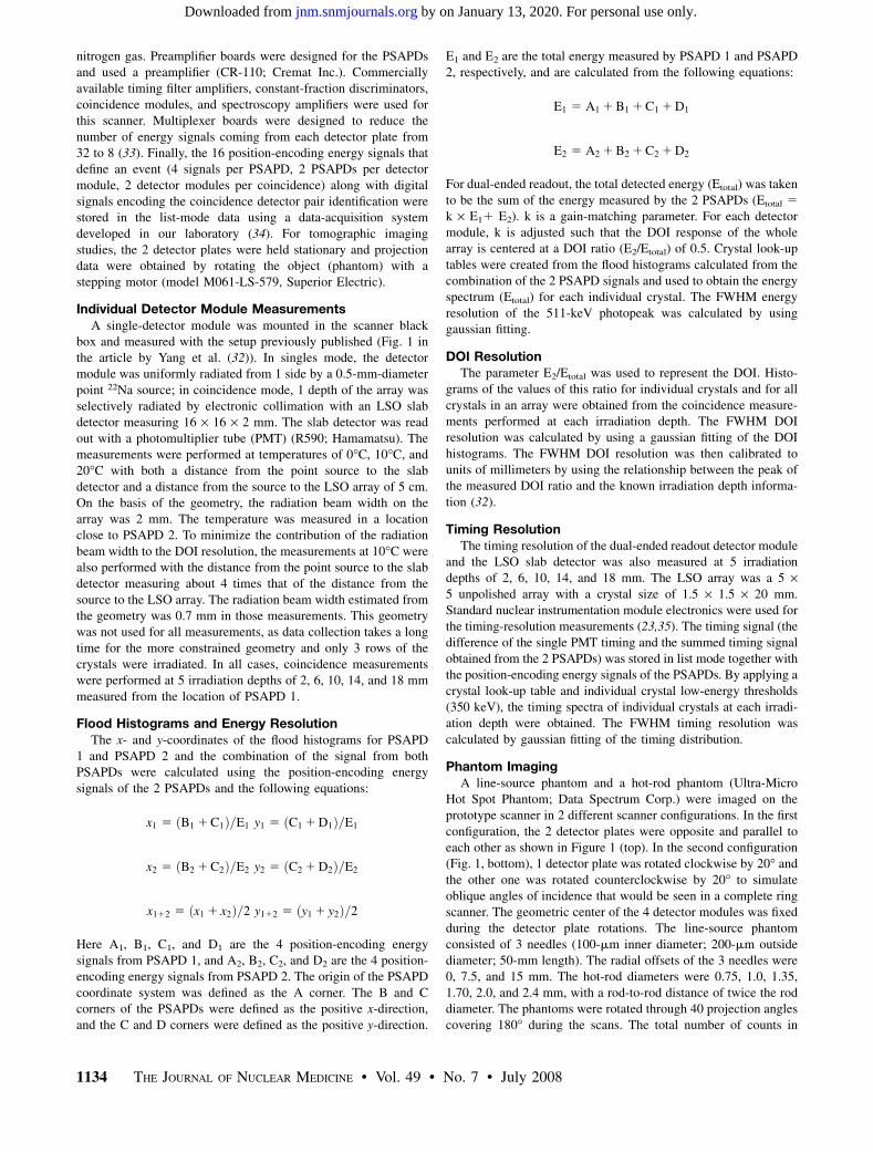
Figure 2 shows the flood histograms calculated by usingthe position-encoding energy signals from PSAPD 1,PSAPD 2, and the combination of both PSAPDs. The floodhistograms obtained using just 1 PSAPD were stronglydepth-dependent. The flood histograms degraded, and thedynamic range was reduced as the interaction point movedfarther from the PSAPD. The edge crystals could not bewell resolved in the flood histogram of the whole array.Several different crystal look-up tables are required for crys-tal identification if the flood histograms of only 1 PSAPDare used. The combined flood histograms from the 2PSAPDs were very good at all depths, and no significant
depth dependence of the flood histograms was observed. Inthe flood histogram of the whole array, all crystals could beclearly resolved. Therefore, flood histograms obtained us-ing signals combined from both PSAPDs are used from thispoint forward.
Effect of Temperature on Detector Performance
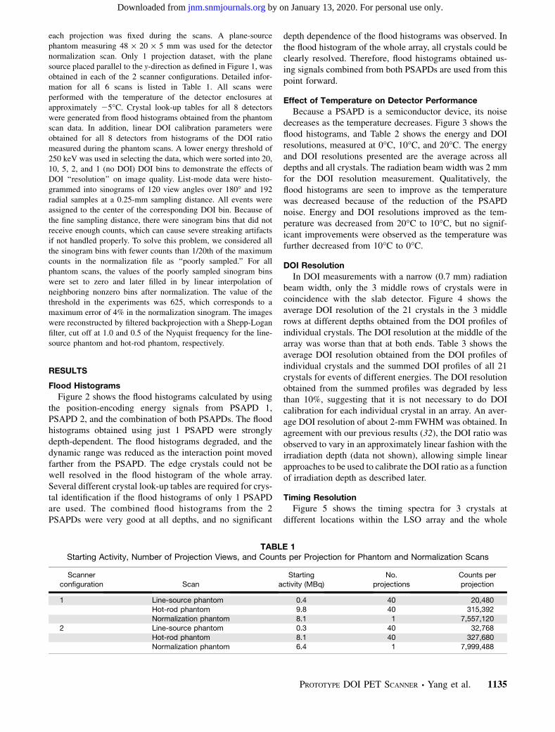
Because a PSAPD is a semiconductor device, its noisedecreases as the temperature decreases. Figure 3 shows theflood histograms, and Table 2 shows the energy and DOIresolutions, measured at 0�C, 10�C, and 20�C. The energyand DOI resolutions presented are the average across alldepths and all crystals. The radiation beam width was 2 mmfor the DOI resolution measurement. Qualitatively, theflood histograms are seen to improve as the temperaturewas decreased because of the reduction of the PSAPDnoise. Energy and DOI resolutions improved as the tem-perature was decreased from 20�C to 10�C, but no signif-icant improvements were observed as the temperature wasfurther decreased from 10�C to 0�C.
DOI Resolution
In DOI measurements with a narrow (0.7 mm) radiationbeam width, only the 3 middle rows of crystals were incoincidence with the slab detector. Figure 4 shows theaverage DOI resolution of the 21 crystals in the 3 middlerows at different depths obtained from the DOI profiles ofindividual crystals. The DOI resolution at the middle of thearray was worse than that at both ends. Table 3 shows theaverage DOI resolution obtained from the DOI profiles ofindividual crystals and the summed DOI profiles of all 21crystals for events of different energies. The DOI resolutionobtained from the summed profiles was degraded by lessthan 10%, suggesting that it is not necessary to do DOIcalibration for each individual crystal in an array. An aver-age DOI resolution of about 2-mm FWHM was obtained. Inagreement with our previous results (32), the DOI ratio wasobserved to vary in an approximately linear fashion with theirradiation depth (data not shown), allowing simple linearapproaches to be used to calibrate the DOI ratio as a functionof irradiation depth as described later.
Timing Resolution
Figure 5 shows the timing spectra for 3 crystals atdifferent locations within the LSO array and the whole
TABLE 1Starting Activity, Number of Projection Views, and Counts per Projection for Phantom and Normalization Scans
Scanner
configuration Scan
Starting
activity (MBq)
No.
projections
Counts per
projection
1 Line-source phantom 0.4 40 20,480Hot-rod phantom 9.8 40 315,392
Normalization phantom 8.1 1 7,557,120
2 Line-source phantom 0.3 40 32,768
Hot-rod phantom 8.1 40 327,680Normalization phantom 6.4 1 7,999,488
PROTOTYPE DOI PET SCANNER • Yang et al. 1135
by on January 13, 2020. For personal use only. jnm.snmjournals.org Downloaded from
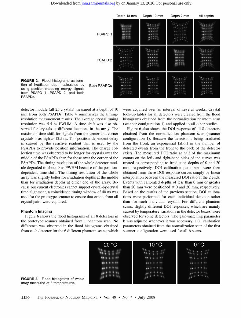
detector module (all 25 crystals) measured at a depth of 10mm from both PSAPDs. Table 4 summarizes the timing-resolution measurement results. The average crystal timingresolution was 5.5 ns FWHM. A time shift was also ob-served for crystals at different locations in the array. Themaximum time shift for signals from the center and cornercrystals is as high as 12.5 ns. This position-dependent delayis caused by the resistive readout that is used by thePSAPDs to provide position information. The charge col-lection time was observed to be longer for crystals over themiddle of the PSAPDs than for those over the corner of thePSAPDs. The timing resolution of the whole detector mod-ule degraded to about 9 ns FWHM because of the position-dependent time shift. The timing resolution of the wholearray was slightly better for irradiation depths at the middlethan for irradiation depths at either end of the array. Be-cause our current electronics cannot support crystal-by-crystaltime alignment, a coincidence timing window of 40 ns wasused for the prototype scanner to ensure that events from allcrystal pairs were captured.
Phantom Imaging
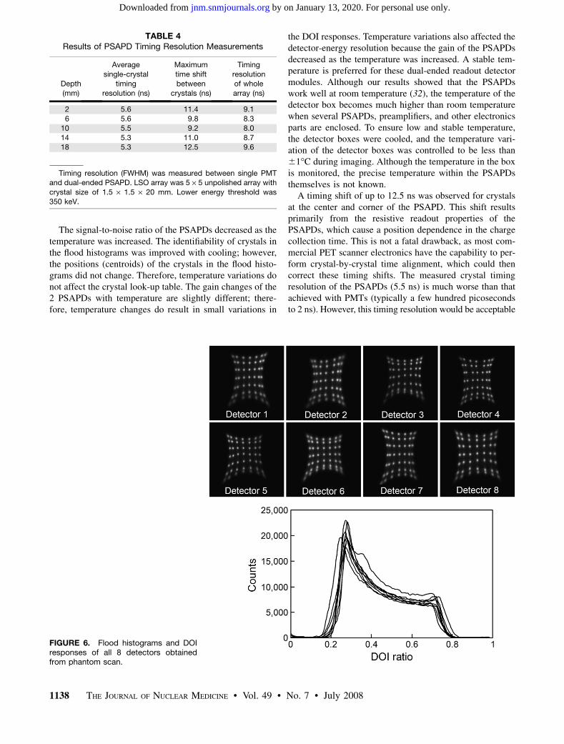
Figure 6 shows the flood histograms of all 8 detectors inthe prototype scanner obtained from 1 phantom scan. Nodifference was observed in the flood histograms obtainedfrom each detector for the 6 different phantom scans, which
were acquired over an interval of several weeks. Crystallook-up tables for all detectors were created from the floodhistograms obtained from the normalization phantom scan(scanner configuration 1) and applied to all other studies.
Figure 6 also shows the DOI response of all 8 detectorsobtained from the normalization phantom scan (scannerconfiguration 1). Because the detector is being irradiatedfrom the front, an exponential falloff in the number ofdetected events from the front to the back of the detectorexists. The measured DOI ratio at half of the maximumcounts on the left- and right-hand sides of the curves wastreated as corresponding to irradiation depths of 0 and 20mm, respectively. DOI calibration parameters were thenobtained from these DOI response curves simply by linearinterpolation between the measured DOI ratio at the 2 ends.Events with calibrated depths of less than 0 mm or greaterthan 20 mm were positioned at 0 and 20 mm, respectively.Based on the results of the previous section, DOI calibra-tions were performed for each individual detector ratherthan for each individual crystal. For different phantomscans, slightly different DOI responses, which are mainlycaused by temperature variations in the detector boxes, wereobserved for some detectors. The gain-matching parameterk was adjusted whenever it was necessary. DOI calibrationparameters obtained from the normalization scan of the firstscanner configuration were used for all 6 scans.
FIGURE 2. Flood histograms as func-tion of irradiation depth calculated byusing position-encoding energy signalsfrom PSAPD 1, PSAPD 2, and bothPSAPDs.
FIGURE 3. Flood histograms of wholearray measured at 3 temperatures.
1136 THE JOURNAL OF NUCLEAR MEDICINE • Vol. 49 • No. 7 • July 2008
by on January 13, 2020. For personal use only. jnm.snmjournals.org Downloaded from
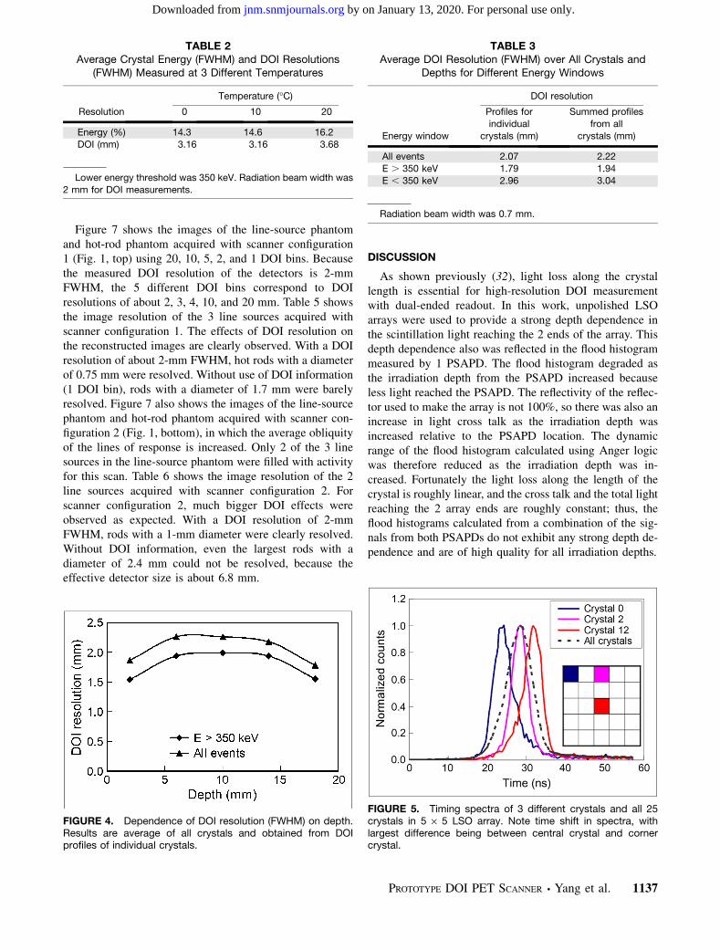
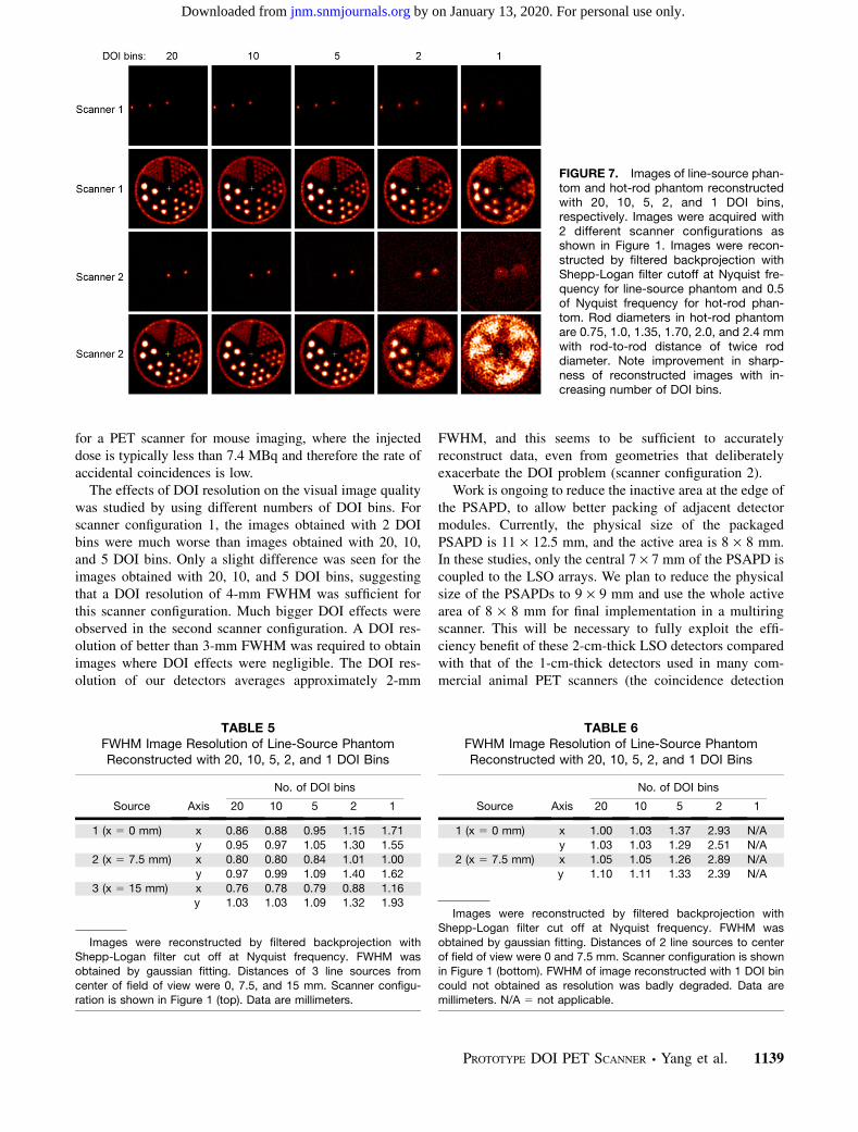
Figure 7 shows the images of the line-source phantomand hot-rod phantom acquired with scanner configuration1 (Fig. 1, top) using 20, 10, 5, 2, and 1 DOI bins. Becausethe measured DOI resolution of the detectors is 2-mmFWHM, the 5 different DOI bins correspond to DOIresolutions of about 2, 3, 4, 10, and 20 mm. Table 5 showsthe image resolution of the 3 line sources acquired withscanner configuration 1. The effects of DOI resolution onthe reconstructed images are clearly observed. With a DOIresolution of about 2-mm FWHM, hot rods with a diameterof 0.75 mm were resolved. Without use of DOI information(1 DOI bin), rods with a diameter of 1.7 mm were barelyresolved. Figure 7 also shows the images of the line-sourcephantom and hot-rod phantom acquired with scanner con-figuration 2 (Fig. 1, bottom), in which the average obliquityof the lines of response is increased. Only 2 of the 3 linesources in the line-source phantom were filled with activityfor this scan. Table 6 shows the image resolution of the 2line sources acquired with scanner configuration 2. Forscanner configuration 2, much bigger DOI effects wereobserved as expected. With a DOI resolution of 2-mmFWHM, rods with a 1-mm diameter were clearly resolved.Without DOI information, even the largest rods with adiameter of 2.4 mm could not be resolved, because theeffective detector size is about 6.8 mm.
DISCUSSION
As shown previously (32), light loss along the crystallength is essential for high-resolution DOI measurementwith dual-ended readout. In this work, unpolished LSOarrays were used to provide a strong depth dependence inthe scintillation light reaching the 2 ends of the array. Thisdepth dependence also was reflected in the flood histogrammeasured by 1 PSAPD. The flood histogram degraded asthe irradiation depth from the PSAPD increased becauseless light reached the PSAPD. The reflectivity of the reflec-tor used to make the array is not 100%, so there was also anincrease in light cross talk as the irradiation depth wasincreased relative to the PSAPD location. The dynamicrange of the flood histogram calculated using Anger logicwas therefore reduced as the irradiation depth was in-creased. Fortunately the light loss along the length of thecrystal is roughly linear, and the cross talk and the total lightreaching the 2 array ends are roughly constant; thus, theflood histograms calculated from a combination of the sig-nals from both PSAPDs do not exhibit any strong depth de-pendence and are of high quality for all irradiation depths.
TABLE 2Average Crystal Energy (FWHM) and DOI Resolutions
(FWHM) Measured at 3 Different Temperatures
Temperature (�C)
Resolution 0 10 20
Energy (%) 14.3 14.6 16.2
DOI (mm) 3.16 3.16 3.68
Lower energy threshold was 350 keV. Radiation beam width was
2 mm for DOI measurements.
FIGURE 4. Dependence of DOI resolution (FWHM) on depth.Results are average of all crystals and obtained from DOIprofiles of individual crystals.
TABLE 3Average DOI Resolution (FWHM) over All Crystals and
Depths for Different Energy Windows
DOI resolution
Energy window
Profiles for
individual
crystals (mm)
Summed profiles
from all
crystals (mm)
All events 2.07 2.22
E . 350 keV 1.79 1.94
E , 350 keV 2.96 3.04
Radiation beam width was 0.7 mm.
FIGURE 5. Timing spectra of 3 different crystals and all 25crystals in 5 · 5 LSO array. Note time shift in spectra, withlargest difference being between central crystal and cornercrystal.
PROTOTYPE DOI PET SCANNER • Yang et al. 1137
by on January 13, 2020. For personal use only. jnm.snmjournals.org Downloaded from
The signal-to-noise ratio of the PSAPDs decreased as thetemperature was increased. The identifiability of crystals inthe flood histograms was improved with cooling; however,the positions (centroids) of the crystals in the flood histo-grams did not change. Therefore, temperature variations donot affect the crystal look-up table. The gain changes of the2 PSAPDs with temperature are slightly different; there-fore, temperature changes do result in small variations in
the DOI responses. Temperature variations also affected thedetector-energy resolution because the gain of the PSAPDsdecreased as the temperature was increased. A stable tem-perature is preferred for these dual-ended readout detectormodules. Although our results showed that the PSAPDswork well at room temperature (32), the temperature of thedetector box becomes much higher than room temperaturewhen several PSAPDs, preamplifiers, and other electronicsparts are enclosed. To ensure low and stable temperature,the detector boxes were cooled, and the temperature vari-ation of the detector boxes was controlled to be less than61�C during imaging. Although the temperature in the boxis monitored, the precise temperature within the PSAPDsthemselves is not known.
A timing shift of up to 12.5 ns was observed for crystalsat the center and corner of the PSAPD. This shift resultsprimarily from the resistive readout properties of thePSAPDs, which cause a position dependence in the chargecollection time. This is not a fatal drawback, as most com-mercial PET scanner electronics have the capability to per-form crystal-by-crystal time alignment, which could thencorrect these timing shifts. The measured crystal timingresolution of the PSAPDs (5.5 ns) is much worse than thatachieved with PMTs (typically a few hundred picosecondsto 2 ns). However, this timing resolution would be acceptable
TABLE 4Results of PSAPD Timing Resolution Measurements
Depth
(mm)
Average
single-crystal
timing
resolution (ns)
Maximum
time shift
between
crystals (ns)
Timing
resolution
of whole
array (ns)
2 5.6 11.4 9.1
6 5.6 9.8 8.3
10 5.5 9.2 8.0
14 5.3 11.0 8.718 5.3 12.5 9.6
Timing resolution (FWHM) was measured between single PMTand dual-ended PSAPD. LSO array was 5 · 5 unpolished array with
crystal size of 1.5 · 1.5 · 20 mm. Lower energy threshold was
350 keV.
FIGURE 6. Flood histograms and DOIresponses of all 8 detectors obtainedfrom phantom scan.
1138 THE JOURNAL OF NUCLEAR MEDICINE • Vol. 49 • No. 7 • July 2008
by on January 13, 2020. For personal use only. jnm.snmjournals.org Downloaded from
for a PET scanner for mouse imaging, where the injecteddose is typically less than 7.4 MBq and therefore the rate ofaccidental coincidences is low.
The effects of DOI resolution on the visual image qualitywas studied by using different numbers of DOI bins. Forscanner configuration 1, the images obtained with 2 DOIbins were much worse than images obtained with 20, 10,and 5 DOI bins. Only a slight difference was seen for theimages obtained with 20, 10, and 5 DOI bins, suggestingthat a DOI resolution of 4-mm FWHM was sufficient forthis scanner configuration. Much bigger DOI effects wereobserved in the second scanner configuration. A DOI res-olution of better than 3-mm FWHM was required to obtainimages where DOI effects were negligible. The DOI res-olution of our detectors averages approximately 2-mm
FWHM, and this seems to be sufficient to accuratelyreconstruct data, even from geometries that deliberatelyexacerbate the DOI problem (scanner configuration 2).
Work is ongoing to reduce the inactive area at the edge ofthe PSAPD, to allow better packing of adjacent detectormodules. Currently, the physical size of the packagedPSAPD is 11 · 12.5 mm, and the active area is 8 · 8 mm.In these studies, only the central 7 · 7 mm of the PSAPD iscoupled to the LSO arrays. We plan to reduce the physicalsize of the PSAPDs to 9 · 9 mm and use the whole activearea of 8 · 8 mm for final implementation in a multiringscanner. This will be necessary to fully exploit the effi-ciency benefit of these 2-cm-thick LSO detectors comparedwith that of the 1-cm-thick detectors used in many com-mercial animal PET scanners (the coincidence detection
FIGURE 7. Images of line-source phan-tom and hot-rod phantom reconstructedwith 20, 10, 5, 2, and 1 DOI bins,respectively. Images were acquired with2 different scanner configurations asshown in Figure 1. Images were recon-structed by filtered backprojection withShepp-Logan filter cutoff at Nyquist fre-quency for line-source phantom and 0.5of Nyquist frequency for hot-rod phan-tom. Rod diameters in hot-rod phantomare 0.75, 1.0, 1.35, 1.70, 2.0, and 2.4 mmwith rod-to-rod distance of twice roddiameter. Note improvement in sharp-ness of reconstructed images with in-creasing number of DOI bins.
TABLE 5FWHM Image Resolution of Line-Source PhantomReconstructed with 20, 10, 5, 2, and 1 DOI Bins
No. of DOI bins
Source Axis 20 10 5 2 1
1 (x 5 0 mm) x 0.86 0.88 0.95 1.15 1.71y 0.95 0.97 1.05 1.30 1.55
2 (x 5 7.5 mm) x 0.80 0.80 0.84 1.01 1.00
y 0.97 0.99 1.09 1.40 1.62
3 (x 5 15 mm) x 0.76 0.78 0.79 0.88 1.16y 1.03 1.03 1.09 1.32 1.93
Images were reconstructed by filtered backprojection withShepp-Logan filter cut off at Nyquist frequency. FWHM was
obtained by gaussian fitting. Distances of 3 line sources from
center of field of view were 0, 7.5, and 15 mm. Scanner configu-ration is shown in Figure 1 (top). Data are millimeters.
TABLE 6FWHM Image Resolution of Line-Source PhantomReconstructed with 20, 10, 5, 2, and 1 DOI Bins
No. of DOI bins
Source Axis 20 10 5 2 1
1 (x 5 0 mm) x 1.00 1.03 1.37 2.93 N/Ay 1.03 1.03 1.29 2.51 N/A
2 (x 5 7.5 mm) x 1.05 1.05 1.26 2.89 N/A
y 1.10 1.11 1.33 2.39 N/A
Images were reconstructed by filtered backprojection with
Shepp-Logan filter cut off at Nyquist frequency. FWHM was
obtained by gaussian fitting. Distances of 2 line sources to centerof field of view were 0 and 7.5 mm. Scanner configuration is shown
in Figure 1 (bottom). FWHM of image reconstructed with 1 DOI bin
could not obtained as resolution was badly degraded. Data aremillimeters. N/A 5 not applicable.
PROTOTYPE DOI PET SCANNER • Yang et al. 1139
by on January 13, 2020. For personal use only. jnm.snmjournals.org Downloaded from
efficiencies of 2-cm- and 1-cm-thick LSO detectors at 511keV are 68% and 34%, respectively).
A question exists as to whether the PSAPDs can workstably for a long time in a scanner. All 16 PSAPDs havealready worked in this prototype scanner for more than 6 mo,suggesting that the technology is robust enough for use in animaging system. Another PET system using PSAPDs butwithout DOI capability has been in operation for more than ayear and has been used for a range of animal studies (35).
CONCLUSION
A prototype PET scanner using detector modules consist-ing of dual-ended readout of pixelated LSO arrays with 2PSAPDs was constructed and tested. Measurements per-formed on individual detector modules showed that a DOIresolution of 2-mm FWHM and an energy resolution of 15%FWHM could be obtained and that all crystals could beclearly resolved in the measured flood histograms of arrayswith submillimeter crystal size. Imaging studies performedon the prototype scanner showed that DOI measurementssignificantly improved the reconstructed spatial resolution.Depth-encoding PET detectors consisting of submillimeterLSO arrays (high spatial resolution) with a 2-cm total thick-ness of LSO (high efficiency) could provide flood histogramsin which all crystals can be identified, DOI and energyresolution are good, and timing resolution is acceptable. Thisapproach is therefore promising for future preclinical PETscanner designs desired to simultaneously achieve highspatial resolution and high sensitivity.
ACKNOWLEDGMENTS
We thank Dr. Ciprian Catana for many useful discussions.This work was funded by NIH grant R01 EB006109 and bysmall business innovation research funding from NationalInstitute of Biomedical Imaging and BioEngineering.
REFERENCES
1. Chatziioannou AF, Cherry SR, Shao YP, et al. Performance evaluation of
microPET: a high-resolution lutetium oxyorthosilicate PET scanner for animal
imaging. J Nucl Med. 1999;40:1164–1175.
2. Cherry SR, Shao Y, Silverman RW, et al. MicroPET: a high resolution PET
scanner for imaging small animals. IEEE Trans Nucl Sci. 1997;44:1161–1166.
3. Lecomte R, deKemp RA, Klein R, et al. Sci-Fri PM Imaging-10: LabPETtm: a
second-generation APD-based digital scanner for high-resolution small animal
PET imaging [abstract]. Med Phys. 2006;33:2671.
4. Missimer J, Madi Z, Honer M, Keller C, Schubiger A, Ametamey SM. Per-
formance evaluation of the 16-module quad-HIDAC small animal PET camera.
Phys Med Biol. 2004;49:2069–2081.
5. Surti S, Karp JS, Perkins AE, et al. Imaging performance of A-PET: a small
animal PET camera. IEEE Trans Med Imaging. 2005;24:844–852.
6. Tai C, Chatziioannou A, Siegel S, et al. Performance evaluation of the microPET P4:
a PET system dedicated to animal imaging. Phys Med Biol. 2001;46:1845–1862.
7. Tai YC, Chatziioannou AF, Yang YF, et al. MicroPET II: design, development
and initial performance of an improved microPET scanner for small-animal
imaging. Phys Med Biol. 2003;48:1519–1537.
8. Tai YC, Ruangma A, Rowland D, et al. Performance evaluation of the microPET
Focus: a third-generation microPET scanner dedicated to animal imaging. J Nucl
Med. 2005;46:455–463.
9. Wang Y, Seidel J, Tsui BMW, Vaquero JJ, Pomper MG. Performance evaluation
of the GE Healthcare eXplore VISTA dual-ring small-animal PET scanner.
J Nucl Med. 2006;47:1891–1900.
10. Yang Y, Tai YC, Siegel S, et al. Optimization and performance evaluation of the
microPET II scanner for in vivo small-animal imaging. Phys Med Biol.
2004;49:2527–2545.
11. Del Guerra A, Bartoli A, Belcari N, et al. Performance evaluation of the fully
engineered YAP-(S)PET scanner for small animal imaging. IEEE Trans Nucl Sci.
2006;53:1078–1083.
12. Huisman MC, Reder S, Weber AW, Ziegler SI, Schwaiger M. Performance
evaluation of the Philips MOSAIC small animal PET scanner. Eur J Nucl Med
Mol Imaging. 2007;34:532–540.
13. Taschereau R, Chatziioannou AF. Monte Carlo simulations of absorbed dose in a
mouse phantom from 18-fluorine compounds. Med Phys. 2007;34:1026–1036.
14. Saoudi A, Pepin CM, Dion F, et al. Investigation of depth-of-interaction by pulse
shape discrimination in multicrystal detectors read out by avalanche photodi-
odes. IEEE Trans Nucl Sci. 1999;46:462–467.
15. Seidel J, Vaquero JJ, Siegel S, Gandler WR, Green MV. Depth identification
accuracy of a three layer phoswich PET detector module. IEEE Trans Nucl Sci.
1999;46:485–490.
16. de Jong H, van Velden FHP, Kloet RW, Buijs FL, Boellaard R, Lammertsma AA.
Performance evaluation of the ECAT HRRT: an LSO-LYSO double layer high
resolution, high sensitivity scanner. Phys Med Biol. 2007;52:1505–1526.
17. Tsuda T, Murayama H, Kitamura K, et al. A four-layer depth of interaction
detector block for small animal PET. IEEE Trans Nucl Sci. 2004;51:2537–2542.
18. Inadama N, Murayama H, Yamaya T, et al. Preliminary evaluation of four-layer
BGO DOI-detector for PET. IEEE Trans Nucl Sci. 2006;53:30–34.
19. Zhang N, Thompson CJ, Cayouette F, Jolly D, Kecani S. A prototype modular
detector design for high resolution positron emission mammography imaging.
IEEE Trans Nucl Sci. 2003;50:1624–1629.
20. Rouze NC, Schmand M, Siegel S, Hutchins GD. Design of a small animal PET
imaging system with 1 microliter volume resolution. IEEE Trans Nucl Sci. 2004;
51:757–763.
21. Stickel JR, Qi JY, Cherry SR. Fabrication and characterization of a 0.5-mm
lutetium oxyorthosilicate detector array for high-resolution PET applications.
J Nucl Med. 2007;48:115–121.
22. Burr KC, Ivan A, Castleberry DE, LeBlanc JW, Shah KS, Farrell R. Evaluation
of a prototype small animal PET detector with depth-of-interaction encoding.
IEEE Trans Nucl Sci. 2004;51:1791–1798.
23. Dokhale PA, Silverman RW, Shah KS, et al. Performance measurements of a
depth-encoding PET detector module based on position-sensitive avalanche
photodiode read-out. Phys Med Biol. 2004;49:4293–4304.
24. Moses WW, Derenzo SE, Melcher CL, Manente RA. A room-temperature LSO/
PIN photodiode pet detector module that measures depth of interaction. IEEE
Trans Nucl Sci. 1995;42:1085–1089.
25. Shao Y, Meadors K, Silverman RW, et al. Dual APD array readout of LSO
crystals: optimization of crystal surface treatment. IEEE Trans Nucl Sci. 2002;
49:649–654.
26. Du HN, Yang YF, Cherry SR. Measurements of wavelength shifting (WLS) fibre
readout for a highly multiplexed, depth-encoding PET detector. Phys Med Biol.
2007;52:2499–2514.
27. Lerche CW, Benlloch JM, Sanchez F, et al. Depth of gamma-ray interaction
within continuous crystals from the width of its scintillation light-distribution.
IEEE Trans Nucl Sci. 2005;52:560–572.
28. Ling T, Lewellen TK, Miyaoka RS. Depth of interaction decoding of a
continuous crystal detector module. Phys Med Biol. 2007;52:2213–2228.
29. Burr KC, Ivan A, LeBlanc J, et al. Evaluation of a position sensitive avalanche
photodiode for PET. IEEE Trans Nucl Sci. 2003;50:792–796.
30. Shah KS, Farrell R, Grazioso R, Harmon ES, Karplus E. Position-sensitive avalanche
photodiodes for gamma-ray imaging. IEEE Trans Nucl Sci. 2002;49:1687–1692.
31. Shah KS, Grazioso R, Farrell R, et al. Position sensitive APDs for small animal
PET imaging. IEEE Trans Nucl Sci. 2004;51:91–95.
32. Yang YF, Dokhale PA, Silverman RW, et al. Depth of interaction resolution
measurements for a high resolution PET detector using position sensitive
avalanche photodiodes. Phys Med Biol. 2006;51:2131–2142.
33. Wu Y, Catana C, Cherry SR. A multiplexer design for position-sensitive avalanche
photodiode detectors in a PET scanner. IEEE Trans Nucl Sci. 2008;55:463–468.
34. Judenhofer MS, Pichler BJ, Cherry SR. Evaluation of high performance data
acquisition boards for simultaneous sampling of fast signals from PET detectors.
Phys Med Biol. 2005;50:29–44.
35. Catana C, Wu YB, Judenhofer MS, Qi JY, Pichler BJ, Cherry SR. Simultaneous
acquisition of multislice PET and MR images: initial results with a MR-
compatible PET scanner. J Nucl Med. 2006;47:1968–1976.
1140 THE JOURNAL OF NUCLEAR MEDICINE • Vol. 49 • No. 7 • July 2008
by on January 13, 2020. For personal use only. jnm.snmjournals.org Downloaded from
Doi: 10.2967/jnumed.107.049791Published online: June 13, 2008.
2008;49:1132-1140.J Nucl Med. Farrell and Simon R. CherryYongfeng Yang, Yibao Wu, Jinyi Qi, Sara St. James, Huini Du, Purushottam A. Dokhale, Kanai S. Shah, Richard A Prototype PET Scanner with DOI-Encoding Detectors
http://jnm.snmjournals.org/content/49/7/1132This article and updated information are available at:
http://jnm.snmjournals.org/site/subscriptions/online.xhtml
Information about subscriptions to JNM can be found at:
http://jnm.snmjournals.org/site/misc/permission.xhtmlInformation about reproducing figures, tables, or other portions of this article can be found online at:
(Print ISSN: 0161-5505, Online ISSN: 2159-662X)1850 Samuel Morse Drive, Reston, VA 20190.SNMMI | Society of Nuclear Medicine and Molecular Imaging
is published monthly.The Journal of Nuclear Medicine
© Copyright 2008 SNMMI; all rights reserved.
by on January 13, 2020. For personal use only. jnm.snmjournals.org Downloaded from