Embed Size (px)
Citation preview

A Preliminary Report on Phygen’s Chromium Nitride Coatings
by
John B. Woodford, Ph.D
and
Mohumad al-Zoubi, Ph.D
Argonne National Laboratory
Introduction
To protect a vulnerable surface from wear or chemical attack, or to enhance its friction
behavior, it is frequently advisable to coat the surface with a hard film. Treating a part made
from a weak material is generally more economical than constructing an entire part out of a more
durable material. However, care must be taken in selecting the coating and matching it to the
substrate, particularly in tribological applications: hard coatings can become a source of highly
abrasive wear particles.
Among the hard coatings in current use are metal nitrides, especially titanium, chromium,
and zirconium; polycrystalline and nanocrystalline diamond; cubic boron nitride; and tetrahedral
amorphous carbon. These may be deposited in several different ways, although two are
primarily used: physical vapor deposition (PVD) and chemical vapor deposition (CVD).
Previously, PVD chromium nitride (CrN) hard coatings have commonly suffered from
poor homogeneity due to the presence of high volume fractions of entrained Cr droplets, and this
has impaired their overall hardness, friction coefficient, and wear resistance. However, the
Phygen coatings that we examined in this study were apparently almost all single-phase nitride,
with only a small fraction of entrained Cr, an apparently noncolumnar grain structure, and

resultant high toughness and wear resistance. Here at Argonne, we have conducted preliminary
tests on Phygen’s coatings.
Sample Description
We sent three hardened H-13 tool steel flats, a dozen M50 stainless steel balls, and two
pieces of single-crystal Si wafer to Phygen for coating. Each flat and four of the balls were
coated with a slightly different CrN formulation/process. The two wafers were coated with
Phygen’s “best” CrN.
The flats and balls were intended for use in friction and wear tests, and the Si wafers were
for characterization of the film. One of the wafers was scribed on its back with a diamond stylus
and cracked, and the cross section was examined by scanning electron microscopy (SEM).
Phygen’s CrN: Physical Features
All pictures in this section were taken with a JEOL 840A scanning electron microscope
(SEM). Figure 1a shows a high-magnification secondary electron (SE) plan view of the coated
wafer, while Figure 1b shows a backscattered electron image (BEI) of the same area. The bright
spheres are entrained Cr droplets. Note that the total percentage of area covered by these
droplets is quite small, and that the largest droplet is only ca. 1 micrometer across.
Figure 2a shows an SE cross-section of the film, and Figure 2b is a BEI of the same area.
It is not clear how much of the brightness variation in the BE image is due to entrained Cr (Z-
contrast) and how much arises from topography. However, three distinct zones may be observed

in the layer. Closest to the Si substrate (i.e., the right side of the image) is an area ca. 100 nm
thick, bright in BE and showing signs of a very fine, possibly columnar grain structure in SE.
The central zone, some 500-600 nm thick, appears mostly dark in BE and has a texture in SE
suggestive of flat grains parallel to the film surface. Finally, the uppermost zone is quite bright
in BE, and in SE exhibits a texture suggesting a more equiaxed grain structure.
The low abundance of entrained droplets suggests that this film may not exhibit the poor
wear properties of conventionally grown coatings. In addition, no porosity is evident in the film,
indicating that it should be tougher than highly porous coatings. This increase in fracture
toughness arises from the tendency of voids to act as crack nucleation sites; lacking such sites,
the film should be more resistant to fracture.
Phygen’s CrN: Friction/Wear Properties
The three CrN-coated flats and one uncoated H-13 steel flat were subjected to an
endurance wear test in the presence of Fischer-Tropsch (FT) synthetic diesel fuel. The tests were
conducted in a Cameron-Plint high-frequency reciprocating rig (HFRR), which moved the flats
back and forth under a fixed 0.25 in. 52100 steel ball carrying a load of 10 N. Under this load
and ball size, the peak and average Hertzian contact stresses were 900 and 600 MPa,
respectively. Wear track length was 21 mm, test duration was 24 hr., and reciprocation
frequency was 3 Hz. Total sliding distance for the test was thus ca. 10.9 km.
Figure 3 shows the friction coefficient traces for the three different coatings and the
uncoated steel. All three coatings offer a reduction in friction over uncoated steel in FT fuel.
CrN #1 shows the least improvement, but is still ca. 20% lower than steel/steel. CrN #2 exhibits

the lowest average friction coefficient (ca. 0.09), but also has a great deal of variation in friction
(±0.02), a feature shared by CrN #1. CrN #3 has the best consistency in friction coefficient and
has only slightly higher friction coefficient on average than CrN #2.
Examination of the wear tracks on the three coated flats showed no sign of wear. There
was an apparent transfer layer of steel from the counterface, but nothing more. The uncoated flat
had a distinct wear track, but optical profilometry showed it to be partially filled with material
transferred from the ball. Because of this, it was impossible to measure wear rates on the flats.
The wear scars on the M50 balls were considerably easier to measure. Figure 4 is a bar
graph of the volume of material lost from the balls; this is a critical design parameter for
considering the degree of counterfacial wear in applications where a coated part slides against an
uncoated surface. Here, CrN #1 is inferior to not only the other two coatings but to steel/steel.
CrN #2 is comparable to steel/steel, and CrN #3 is superior. However, the differences between
the four results are sufficiently small that they could be attributed to measurement error; lacking
a larger number of wear tests for statistical analysis, we could draw no firm conclusions from the
wear data.
Based on these results, it appears that CrN #3 is the best overall in FT-fuel-lubricated
applications–it wears the counterface about as much as uncoated steel while providing a
substantial reduction in friction over that of uncoated steel in FT fuel. The low spread in friction
value compared to that of CrN #1 and #2 may indicate a more homogeneous coating.
Phygen’s CrN: Other Mechanical Properties
The adhesion of the coating and its fracture toughness were qualitatively determined by

indentation. Each of the three H-13 flats was indented with a Rockwell hardness tester in
Rockwell A mode (60 kg load, diamond brale indenter). The indentations were examined by
SEM. Figures 5-7 show the indentations on CrN #1, #2, and #3, respectively. Although some
delamination is observed in #1 and #3, the coating adhered extremely well to the area around the
indentations. Under the same conditions, a diamondlike carbon (DLC) coating with a high
percentage of sp3-bonded carbon delaminated in a large area around the indentation. The cracks
radiating outward from the indentation are not very long (ca. 10-30 micrometers), a further
indication of the film toughness.
Phygen’s CrN as an NFC Undercoat
One potential use for this coating is as an undercoat for Argonne’s near-frictionless
carbon (NFC), a form of DLC deposited by plasma-assisted chemical vapor deposition
(PACVD). In dry inert environments, NFC coatings exhibit the lowest friction coefficient of any
solid material, i.e., 0.001. Even in lubricated or open-air conditions, NFC-coated parts show
extremely low wear and friction. Phygen’s CrN may be used to support NFC films and to
provide enhanced part protection if the NFC coating wears through or otherwise fails.
It is impossible to coat NFC onto most materials without first applying a bond coat by
sputtering or PACVD; because chromium has been used successfully as a bond coat, it was
hoped that NFC could be deposited directly onto CrN. This was attempted with one of the pieces
of CrN-coated silicon wafer. The attempt was unsuccessful. Although a carbonaceous layer was
deposited onto the CrN, it was completely graphitic and peeled off readily. We intend to try
using our current bond coating technology as an intermediate layer, but that has not been done

yet.
Conclusions
Phygen’s CrN coating affords considerable protection to sliding surfaces, and it reduces
friction and wear in lubricated contacts. Its homogeneity is quite good, which should translate
into improved mechanical properties.
Future Work
The following work is either planned or in progress:
• Measuring the density of the CrN films (in progress).
• Nanoindentation tests to measure hardness and elastic modulus of the CrN film (in progress).
• Attempting to coat CrN with NFC by current bond-coating method (in progress).
• Scuffing tests of CrN #3, both dry and in fuels and lubricants (in progress).
• Endurance tests on CrN #3 in conventional diesel fuel (in progress).
• Evaluating grain structure and texture by glancing-angle X-ray diffraction, cross-sectional
transmission electron microscopy, orientation image mapping, and high-magnification SEM
(planned).
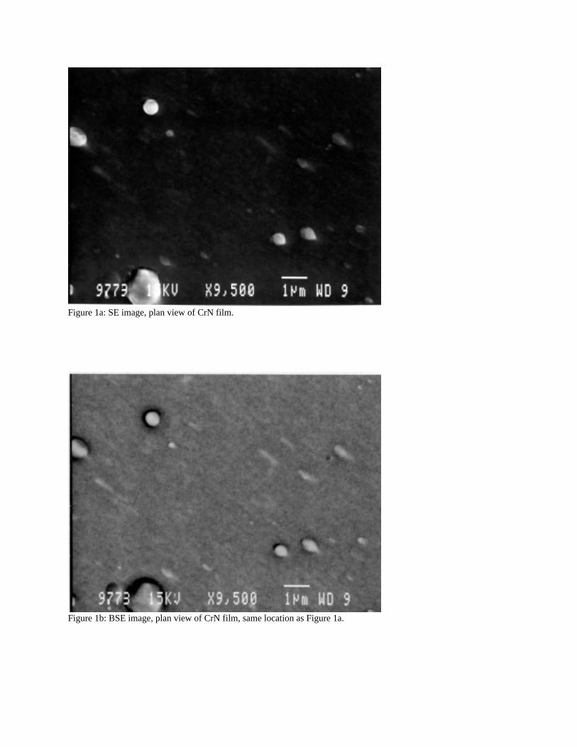
Figure 1a: SE image, plan view of CrN film.
Figure 1b: BSE image, plan view of CrN film, same location as Figure 1a.

Figure 2a: SE image, cross-section of CrN film on Si. The Si substrateis to the right of the film.
Figure 2b: BE image, cross-section of CrN film on Si, same locationas Figure 2a.

Figure 3: Plot of friction coefficient vs. sliding distance for reciprocating tests described in the text.

Figure 4: Graph comparing ball wear rates for the reciprocating tests described in the text.

Figure 5: SE image of indent in CrN #1 on H-13 steel.
Figure 6: SE image of indent in CrN #2 on H-13 steel.

Figure 7: SE image of indent in CrN #3 on H-13 steel.