Embed Size (px)
Citation preview
A Preliminary Linac Design to Inject the CIAE 300 MeV Storage Ring
(Chinese Institute for Atomic Energy)
J. Stovall, K. Crandall, L. Young, J. Billen
30 September, 2013 RAL, UK
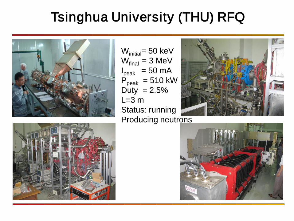
Winitial= 50 keV Wfinal = 3 MeV Ipeak = 50 mA Ppeak = 510 kW Duty = 2.5% L=3 m Status: running Producing neutrons
Tsinghua University (THU) RFQ
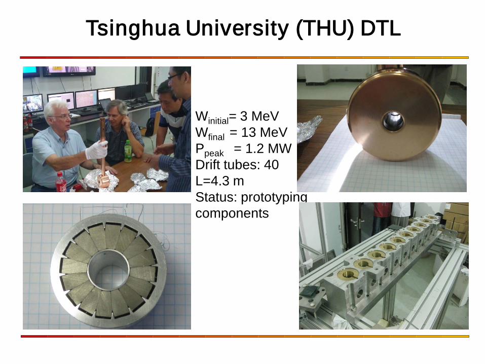
Winitial= 3 MeV Wfinal = 13 MeV Ppeak = 1.2 MW Drift tubes: 40 L=4.3 m Status: prototyping components
Tsinghua University (THU) DTL
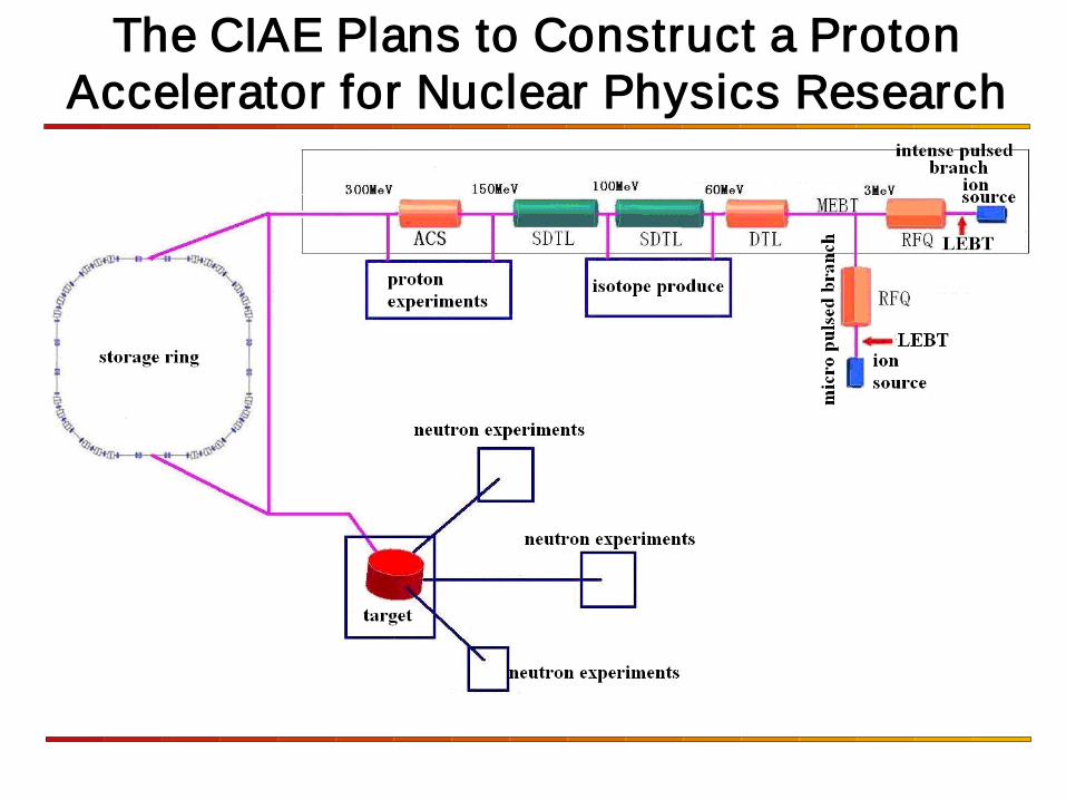
The CIAE Plans to Construct a Proton Accelerator for Nuclear Physics Research
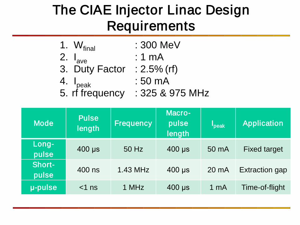
1. Wfinal : 300 MeV 2. Iave : 1 mA 3. Duty Factor : 2.5% (rf) 4. Ipeak : 50 mA 5. rf frequency : 325 & 975 MHz
The CIAE Injector Linac Design Requirements
Mode Pulse length
Frequency Macro-pulse length
Ipeak Application
Long-pulse
400 μs 50 Hz 400 μs 50 mA Fixed target
Short-pulse
400 ns 1.43 MHz 400 μs 20 mA Extraction gap
μ-pulse <1 ns 1 MHz 400 μs 1 mA Time-of-flight
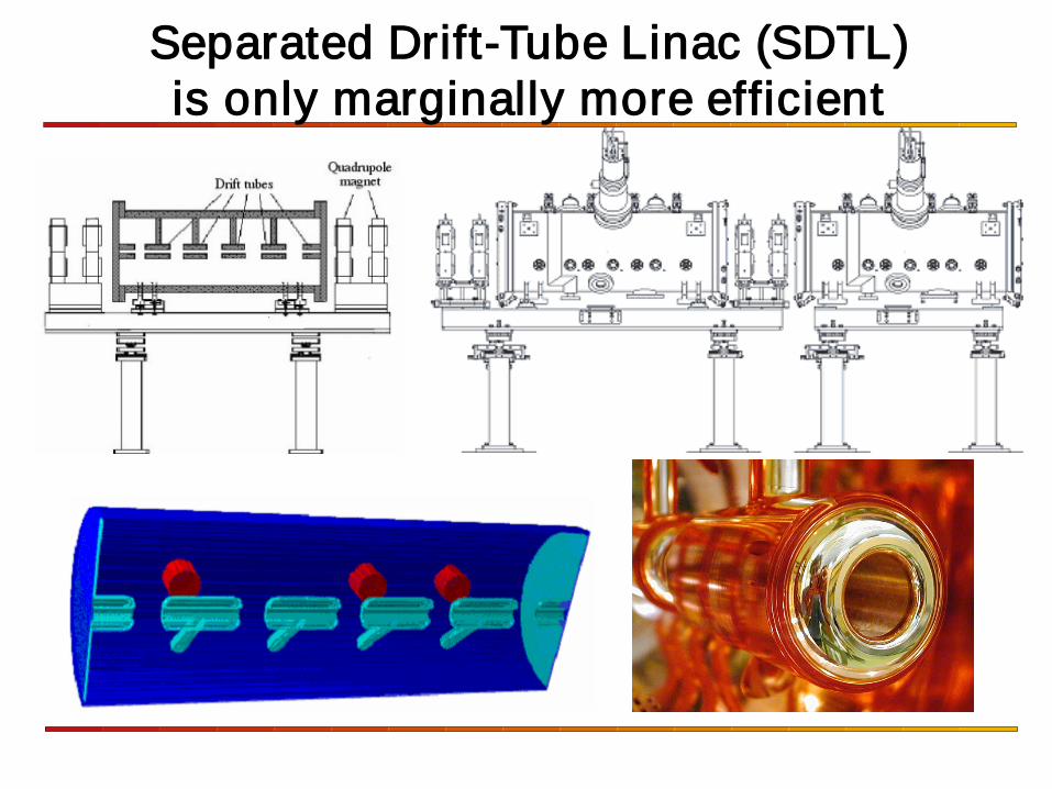
Separated Drift-Tube Linac (SDTL) is only marginally more efficient
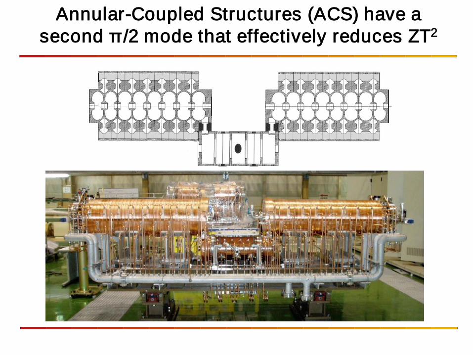
Annular-Coupled Structures (ACS) have a second π/2 mode that effectively reduces ZT2
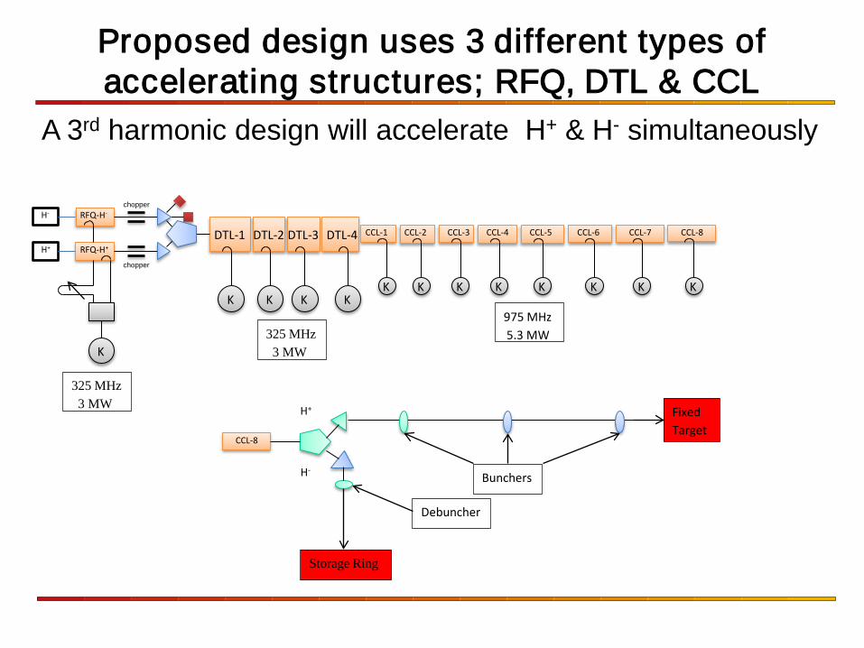
A 3rd harmonic design will accelerate H+ & H- simultaneously
chopper
chopper
K
K K K K K K K K K K K K
DTL-1 DTL-2 DTL-3 DTL-4 CCL-1 CCL-2 CCL-3 CCL-4 CCL-5 CCL-6 CCL-7 CCL-8
RFQ-H-
RFQ-H+
H-
H+
CCL-8
H-
H+
Storage Ring
Fixed Target
Bunchers
Debuncher
325 MHz 3 MW
975 MHz 5.3 MW
Proposed design uses 3 different types of accelerating structures; RFQ, DTL & CCL
325 MHz 3 MW
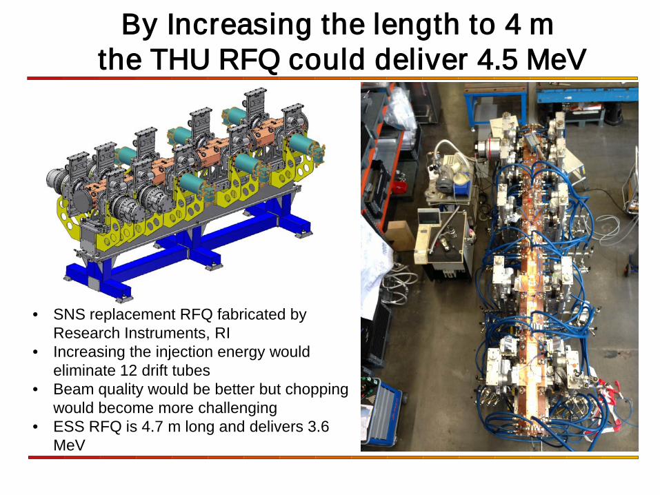
By Increasing the length to 4 m the THU RFQ could deliver 4.5 MeV
• SNS replacement RFQ fabricated by Research Instruments, RI
• Increasing the injection energy would eliminate 12 drift tubes
• Beam quality would be better but chopping would become more challenging
• ESS RFQ is 4.7 m long and delivers 3.6 MeV
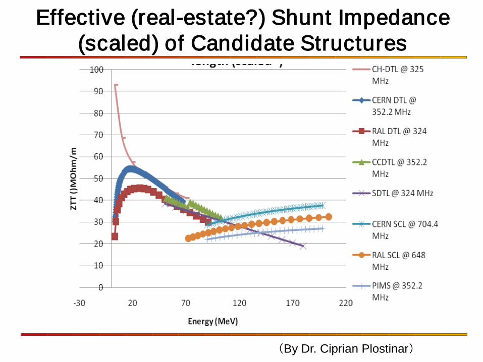
Effective (real-estate?) Shunt Impedance (scaled) of Candidate Structures
(By Dr. Ciprian Plostinar)
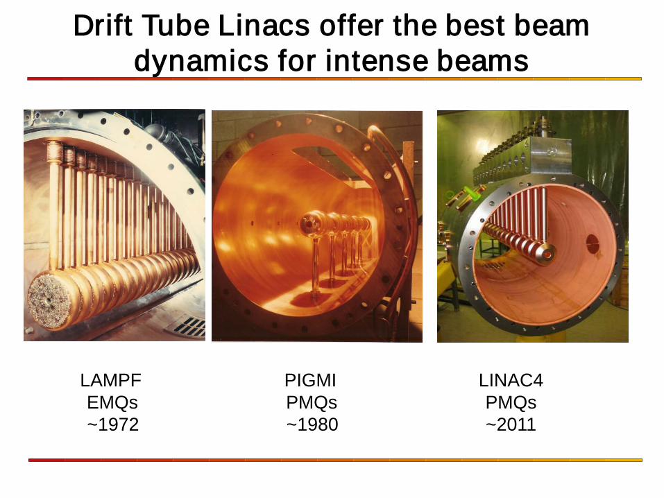
Drift Tube Linacs offer the best beam dynamics for intense beams
LAMPF PIGMI LINAC4 EMQs PMQs PMQs ~1972 ~1980 ~2011
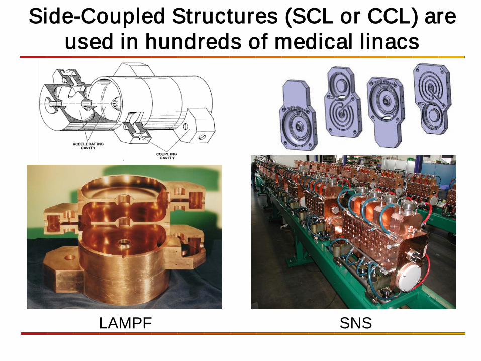
Side-Coupled Structures (SCL or CCL) are used in hundreds of medical linacs
LAMPF SNS
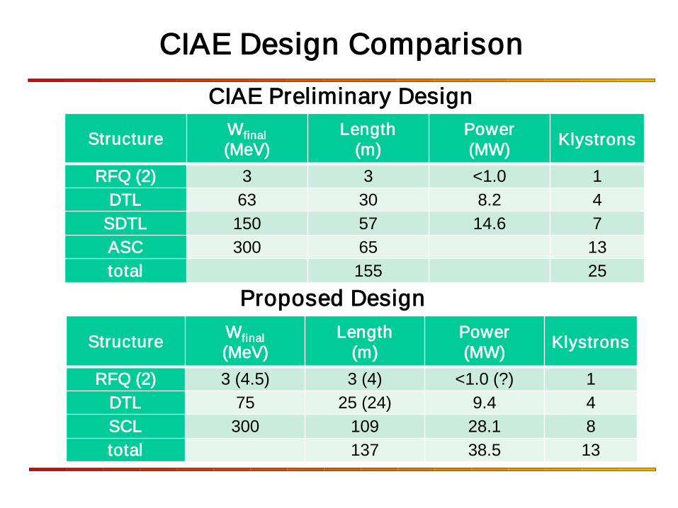
CIAE Design Comparison CIAE Preliminary Design
Proposed Design
Structure Wfinal (MeV)
Length (m)
Power (MW) Klystrons
RFQ (2) 3 3 <1.0 1 DTL 63 30 8.2 4
SDTL 150 57 14.6 7 ASC 300 65 13 total 155 25
Structure Wfinal (MeV)
Length (m)
Power (MW) Klystrons
RFQ (2) 3 (4.5) 3 (4) <1.0 (?) 1 DTL 75 25 (24) 9.4 4 SCL 300 109 28.1 8 total 137 38.5 13
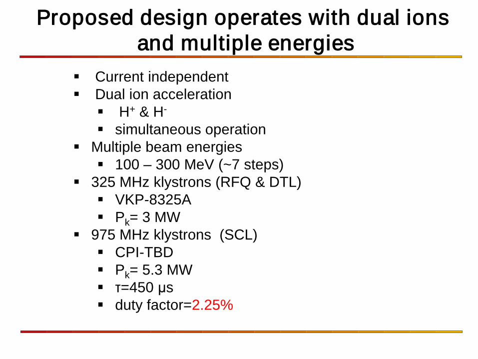
Proposed design operates with dual ions and multiple energies
Current independent Dual ion acceleration H+ & H-
simultaneous operation Multiple beam energies 100 – 300 MeV (~7 steps)
325 MHz klystrons (RFQ & DTL) VKP-8325A Pk= 3 MW
975 MHz klystrons (SCL) CPI-TBD Pk= 5.3 MW τ=450 μs duty factor=2.25%
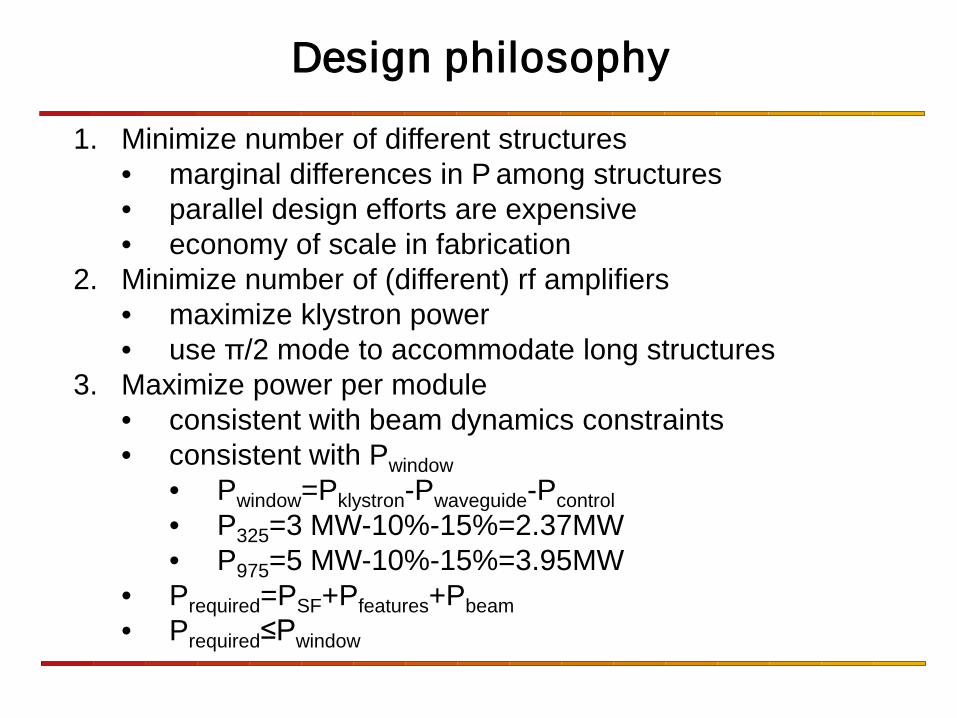
1. Minimize number of different structures • marginal differences in P among structures • parallel design efforts are expensive • economy of scale in fabrication
2. Minimize number of (different) rf amplifiers • maximize klystron power • use π/2 mode to accommodate long structures
3. Maximize power per module • consistent with beam dynamics constraints • consistent with Pwindow
• Pwindow=Pklystron-Pwaveguide-Pcontrol • P325=3 MW-10%-15%=2.37MW • P975=5 MW-10%-15%=3.95MW
• Prequired=PSF+Pfeatures+Pbeam • Prequired≤Pwindow
Design philosophy
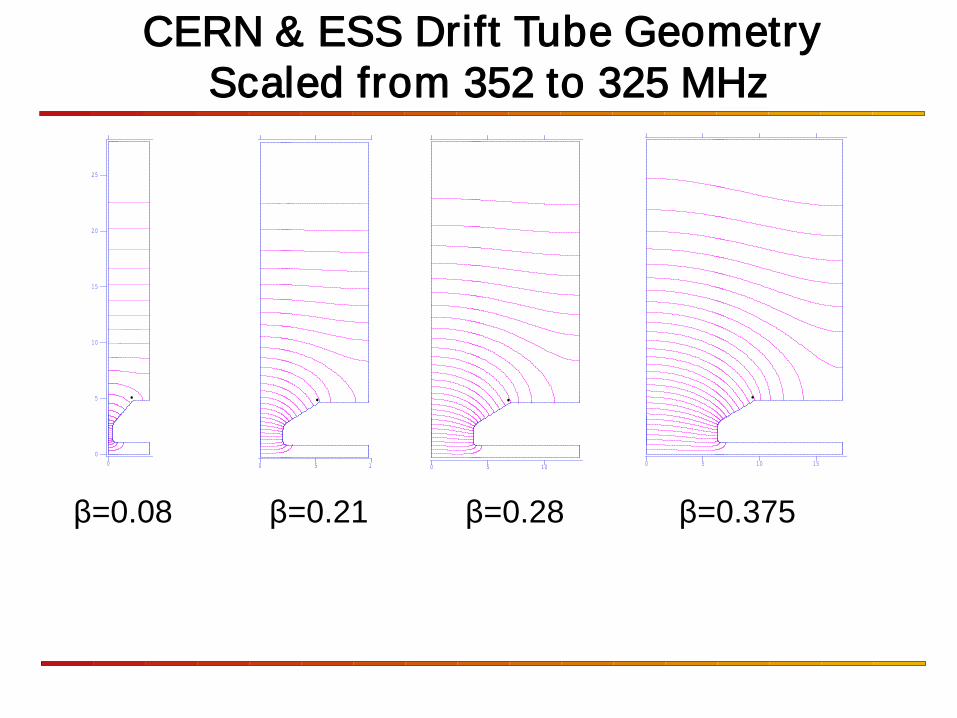
CERN & ESS Drift Tube Geometry Scaled from 352 to 325 MHz
0
5
10
15
20
25
0
0 5 10
0 5 10
0 5 10 15
β=0.08 β=0.21 β=0.28 β=0.375
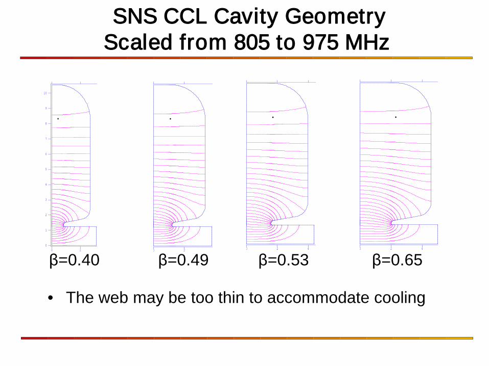
SNS CCL Cavity Geometry Scaled from 805 to 975 MHz
0
1
2
3
4
5
6
7
8
9
10
0 2
0 2
0 2 4
0 2 4
β=0.40 β=0.49 β=0.53 β=0.65
• The web may be too thin to accommodate cooling
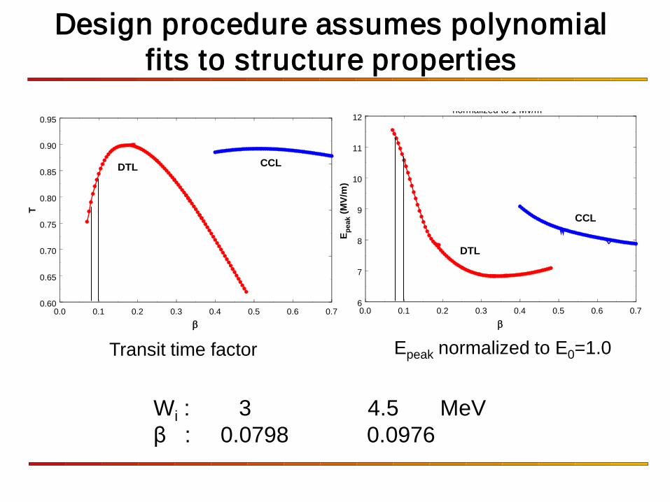
Design procedure assumes polynomial fits to structure properties
0.0 0.1 0.2 0.3 0.4 0.5 0.6 0.7β
0.60
0.65
0.70
0.75
0.80
0.85
0.90
0.95
T
DTL CCL
0.0 0.1 0.2 0.3 0.4 0.5 0.6 0.7β
6
7
8
9
10
11
12
E peak
(MV/
m)
normalized to 1 Mv/m
DTL
CCL
Epeak normalized to E0=1.0 Transit time factor
Wi : 3 4.5 MeV β : 0.0798 0.0976
0.0 0.1 0.2 0.3 0.4 0.5 0.6 0.7β
20
30
40
50
60
70
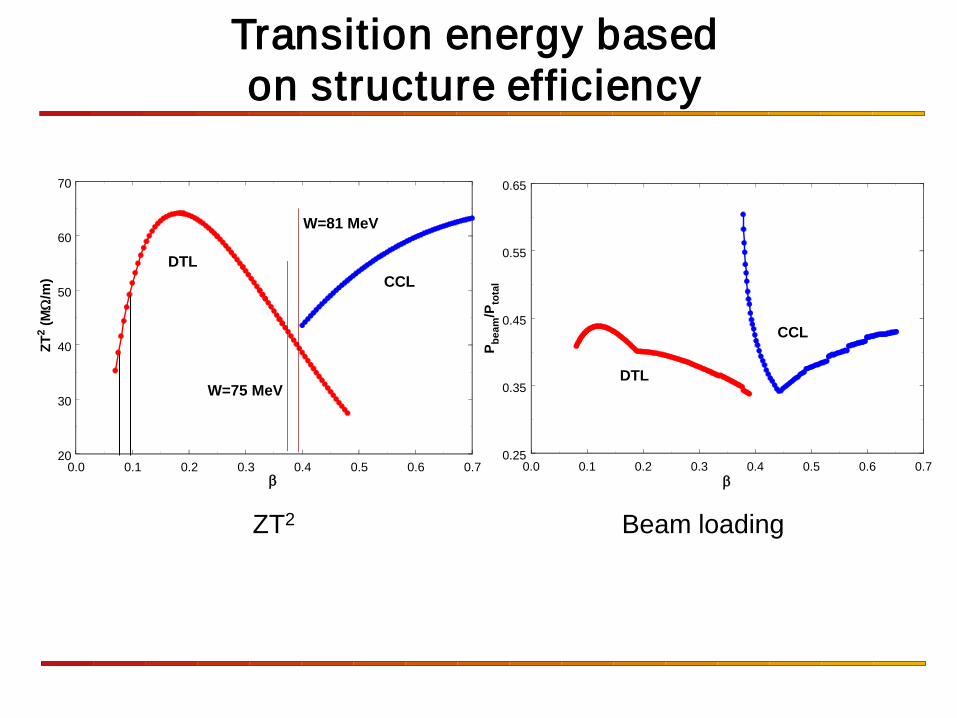
ZT2 (M
Ω/m
)
CCLDTL
W=75 MeV
W=81 MeV
0.0 0.1 0.2 0.3 0.4 0.5 0.6 0.7β
0.25
0.35
0.45
0.55
0.65
P beam
/Pto
tal
DTL
CCL
ZT2 Beam loading
Transition energy based on structure efficiency
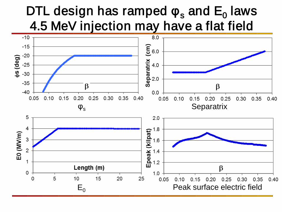
DTL design has ramped φs and E0 laws 4.5 MeV injection may have a flat field
φs Separatrix
E0 Peak surface electric field
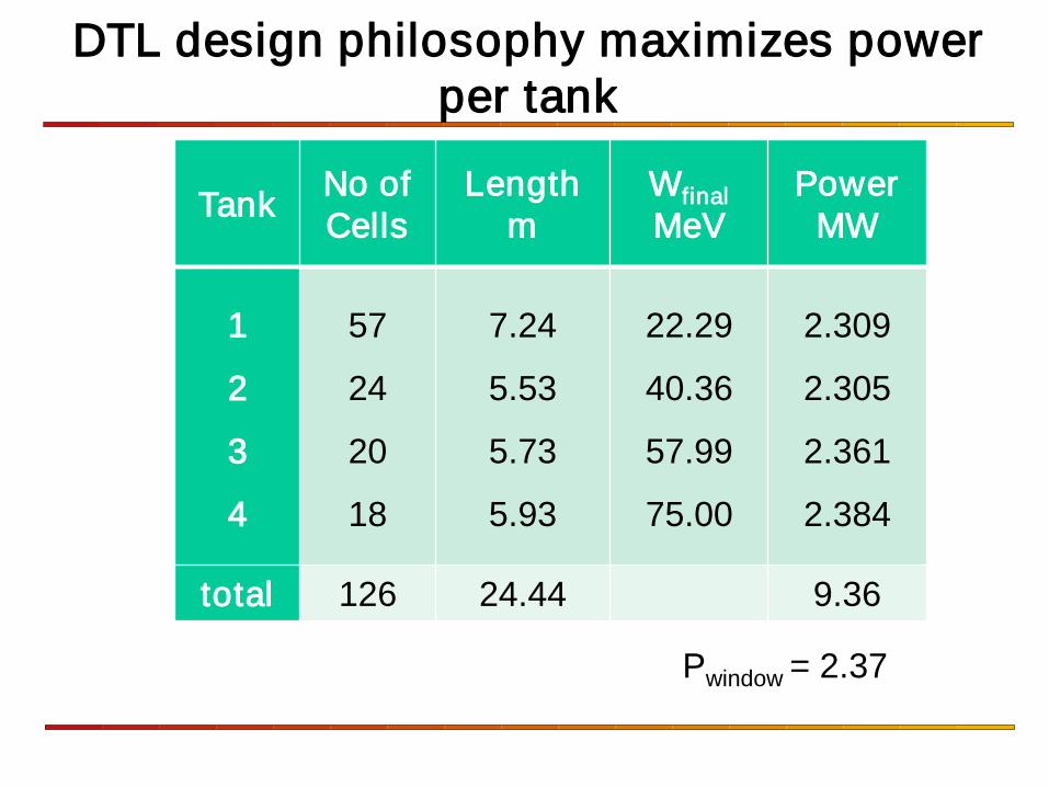
DTL design philosophy maximizes power per tank
Tank No of Cells
Length m
Wfinal MeV
Power MW
1
2
3
4
57
24
20
18
7.24
5.53
5.73
5.93
22.29
40.36
57.99
75.00
2.309
2.305
2.361
2.384
total 126 24.44 9.36
Pwindow = 2.37
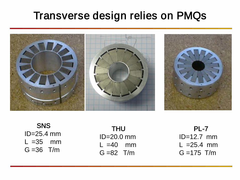
Transverse design relies on PMQs
SNS ID=25.4 mm L =35 mm G =36 T/m
PL-7 ID=12.7 mm L =25.4 mm G =175 T/m
THU ID=20.0 mm L =40 mm G =82 T/m
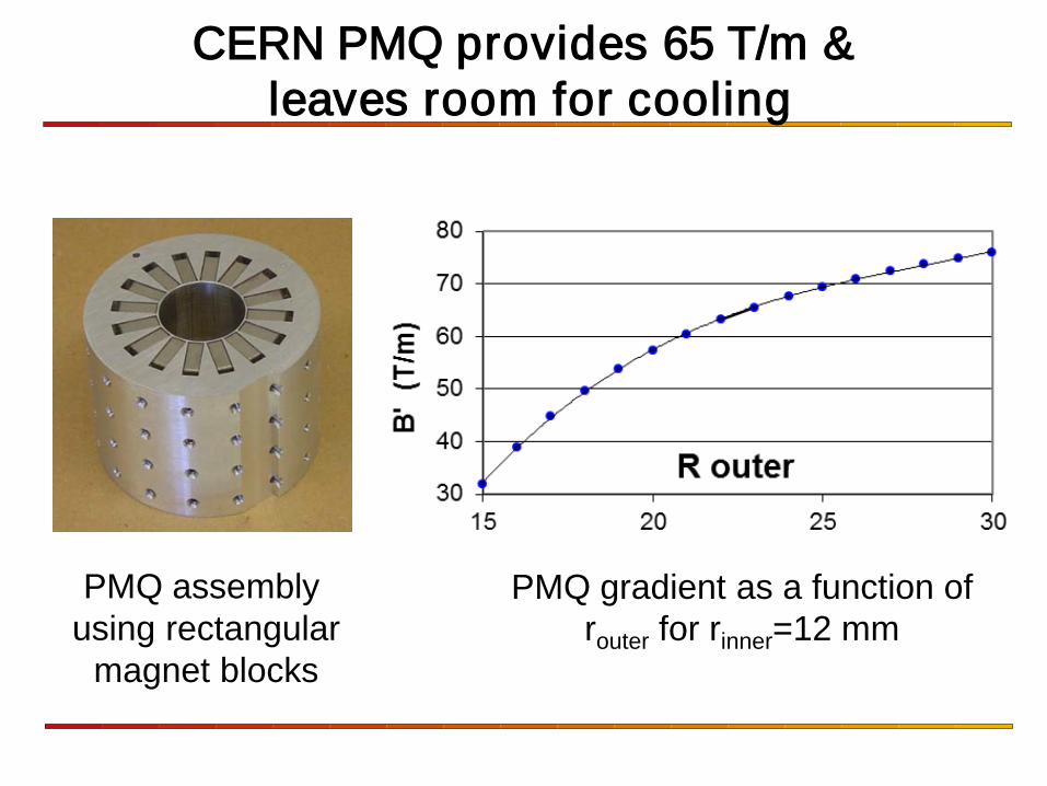
CERN PMQ provides 65 T/m & leaves room for cooling
PMQ assembly using rectangular
magnet blocks
PMQ gradient as a function of router for rinner=12 mm
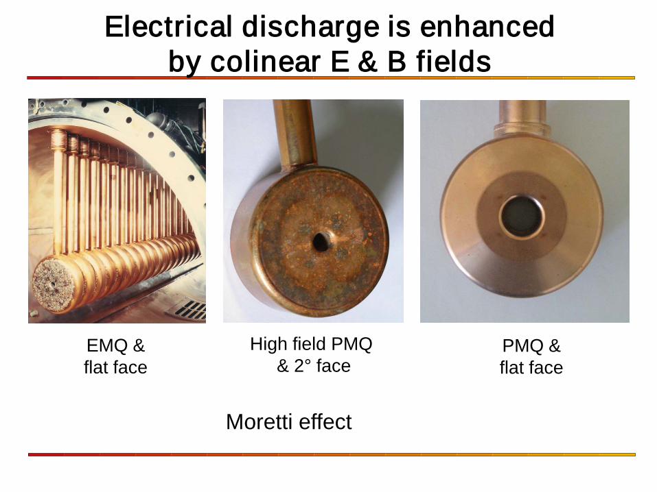
Electrical discharge is enhanced by colinear E & B fields
EMQ & flat face
High field PMQ & 2° face
PMQ & flat face
Moretti effect
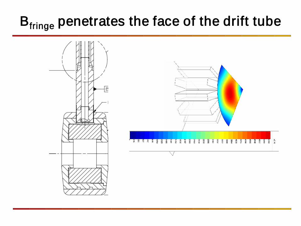
Bfringe penetrates the face of the drift tube
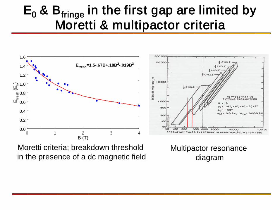
E0 & Bfringe in the first gap are limited by Moretti & multipactor criteria
0 1 2 3 4B (T)
0.0
0.2
0.4
0.6
0.8
1.0
1.2
1.4
1.6
Etre
sh (E
k)
Etresh=1.5-.67B+.18B2-.019B3
Moretti criteria; breakdown threshold in the presence of a dc magnetic field
Multipactor resonance diagram
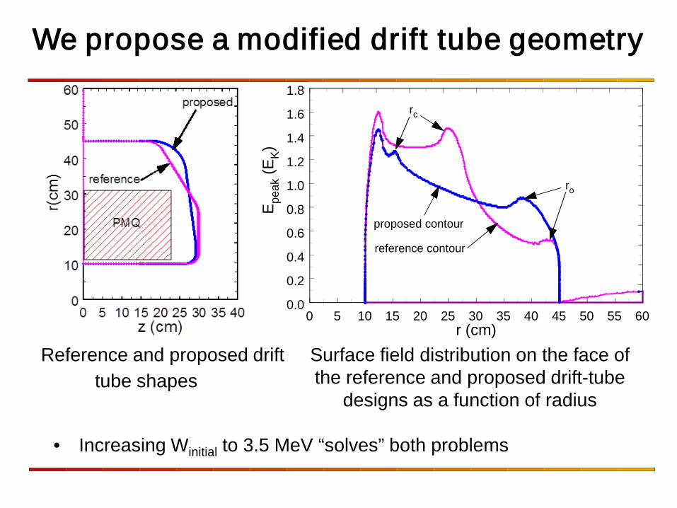
We propose a modified drift tube geometry
0 5 10 15 20 25 30 35 40 45 50 55 60r (cm)
0.0
0.2
0.4
0.6
0.8
1.0
1.2
1.4
1.6
1.8
E peak
(EK)
reference contour
proposed contour
rc
ro
Reference and proposed drift tube shapes
Surface field distribution on the face of the reference and proposed drift-tube
designs as a function of radius
• Increasing Winitial to 3.5 MeV “solves” both problems
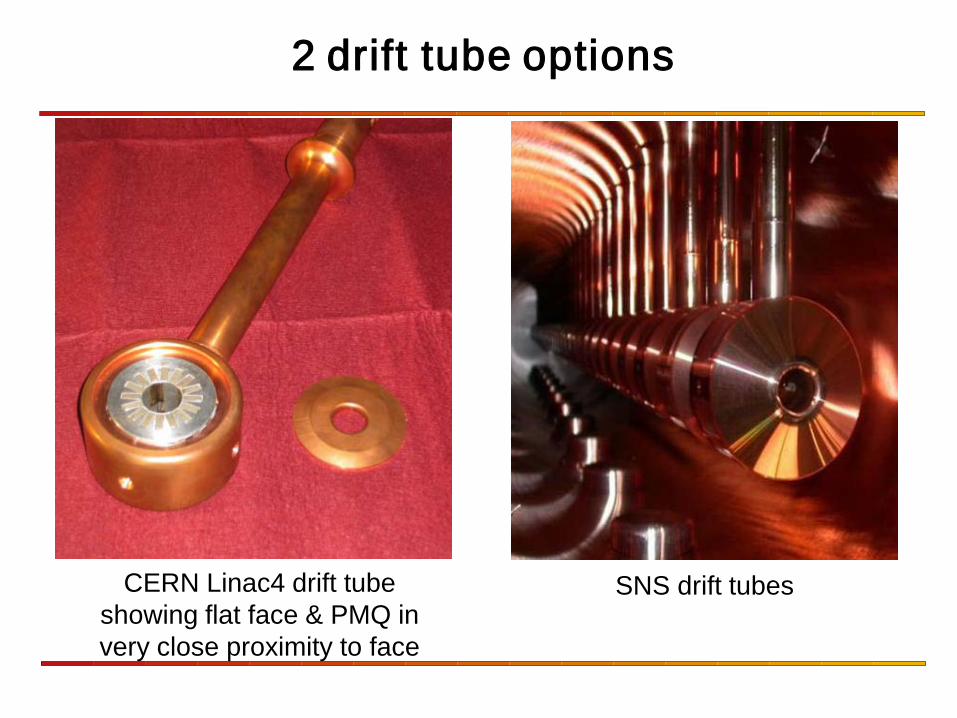
2 drift tube options
CERN Linac4 drift tube showing flat face & PMQ in very close proximity to face
SNS drift tubes
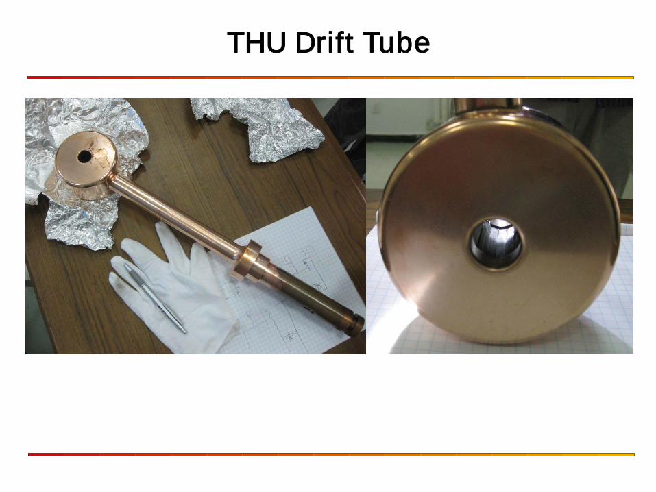
THU Drift Tube
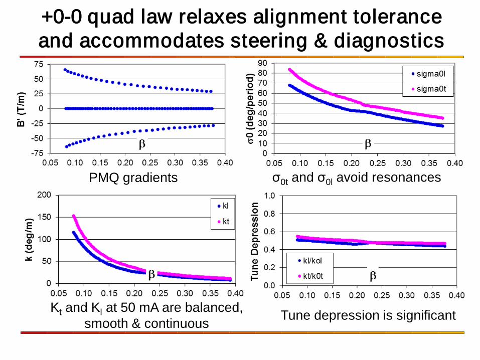
+0-0 quad law relaxes alignment tolerance and accommodates steering & diagnostics
PMQ gradients σ0t and σ0l avoid resonances
Kt and Kl at 50 mA are balanced, smooth & continuous Tune depression is significant
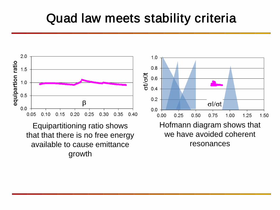
Quad law meets stability criteria
Equipartitioning ratio shows that that there is no free energy
available to cause emittance growth
Hofmann diagram shows that we have avoided coherent
resonances
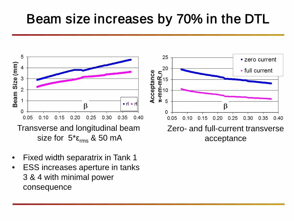
Beam size increases by 70% in the DTL
Transverse and longitudinal beam size for 5*εrms & 50 mA
• Fixed width separatrix in Tank 1 • ESS increases aperture in tanks
3 & 4 with minimal power consequence
Zero- and full-current transverse acceptance
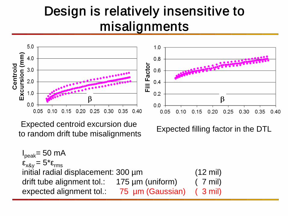
Design is relatively insensitive to misalignments
Expected centroid excursion due to random drift tube misalignments Expected filling factor in the DTL
Ipeak= 50 mA εx&y = 5*εrms initial radial displacement: 300 µm (12 mil) drift tube alignment tol.: 175 µm (uniform) ( 7 mil) expected alignment tol.: 75 µm (Gaussian) ( 3 mil)
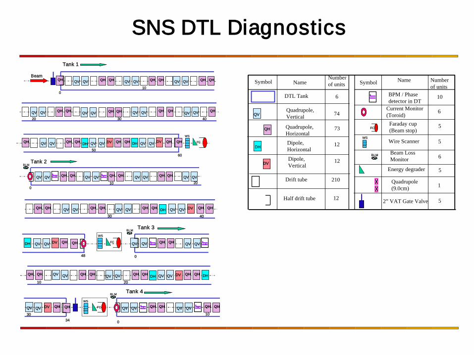
SNS DTL Diagnostics
Tank 1
0
0
Tank 2 60
BeamQV QH QH QVQV QHQH QVQV QHQHQV
QV QV QH QH QV QHQH QVQV QHQV QV QHQV
QH QV QV QH QH QV QV QHQH QVQV QH
QV QV QH QH QH QHQV QV QV QHQH QVQV QV
QH
10
20 30 40
50
QH
QH
10 20
DV DV DH DH FC
WS
BLM
48 0
Tank 3
Tank 4
34 0
QH QH QV QHQHQV QV QV QH QH QV QHQHQV
QV QHQV QV QHQH QVQV
QHQH QV QV QHQH QV QV QHQH QH
QVQV QH QV QV QH QH QV QV QH QH
QV QV QH
QH
QVQH
4030
10 20
30 10
DV
DV
DV
DV
DH DH
DH
DH FC
WS
FC
WS
BLM
BLM
DTL Tank BPM / Phasedetector in DT
Current Monitor(Toroid)
Wire Scanner
Faraday cup(Beam stop)
2” VAT Gate Valve
Quadrupole,Vertical
Quadrupole,Horizontal
Symbol NameNumberof units
6
Symbol Name Numberof units
Drift tube
74
73
5
10
6
5
5
Quadrupole(9.0cm) 1
FC
QV
QH
Half drift tube
WS
210
12
DH
DV
Dipole,Horizontal
Dipole,Vertical
12
12Energy degrader 5
Beam LossMonitor
BLM 6
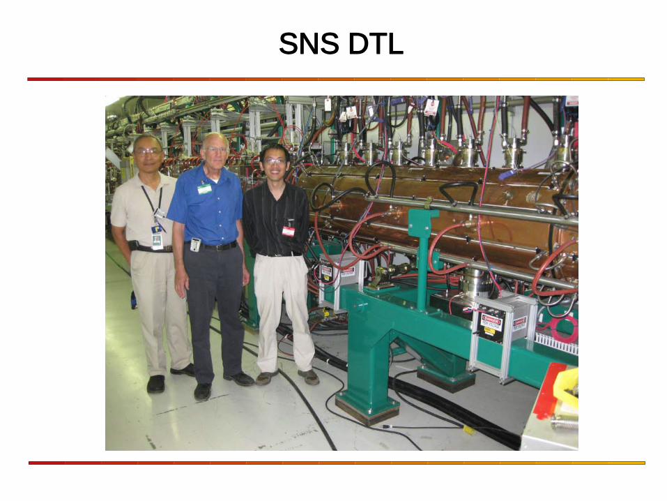
SNS DTL
KK
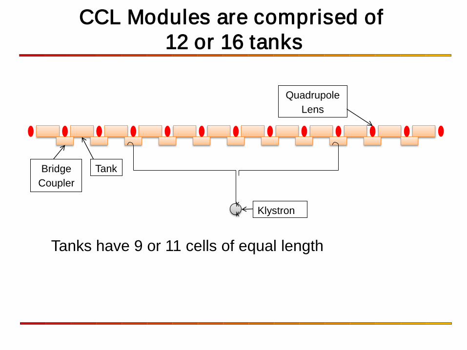
Tank Bridge Coupler
Quadrupole Lens
Klystron
CCL Modules are comprised of 12 or 16 tanks
Tanks have 9 or 11 cells of equal length
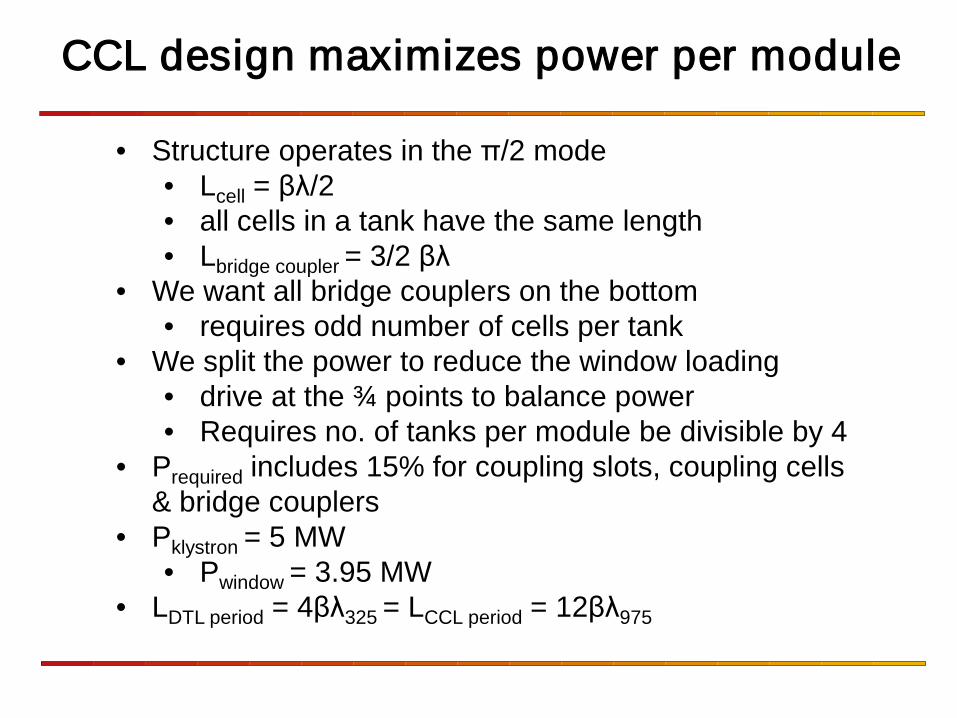
CCL design maximizes power per module
• Structure operates in the π/2 mode • Lcell = βλ/2 • all cells in a tank have the same length • Lbridge coupler = 3/2 βλ
• We want all bridge couplers on the bottom • requires odd number of cells per tank
• We split the power to reduce the window loading • drive at the ¾ points to balance power • Requires no. of tanks per module be divisible by 4
• Prequired includes 15% for coupling slots, coupling cells & bridge couplers
• Pklystron = 5 MW • Pwindow = 3.95 MW
• LDTL period = 4βλ325 = LCCL period = 12βλ975
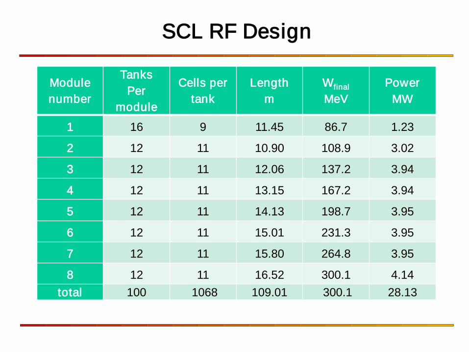
SCL RF Design
Module number
Tanks Per
module
Cells per tank
Length m
Wfinal
MeV Power
MW
1 16 9 11.45 86.7 1.23
2 12 11 10.90 108.9 3.02
3 12 11 12.06 137.2 3.94
4 12 11 13.15 167.2 3.94
5 12 11 14.13 198.7 3.95
6 12 11 15.01 231.3 3.95
7 12 11 15.80 264.8 3.95
8 12 11 16.52 300.1 4.14 total 100 1068 109.01 300.1 28.13
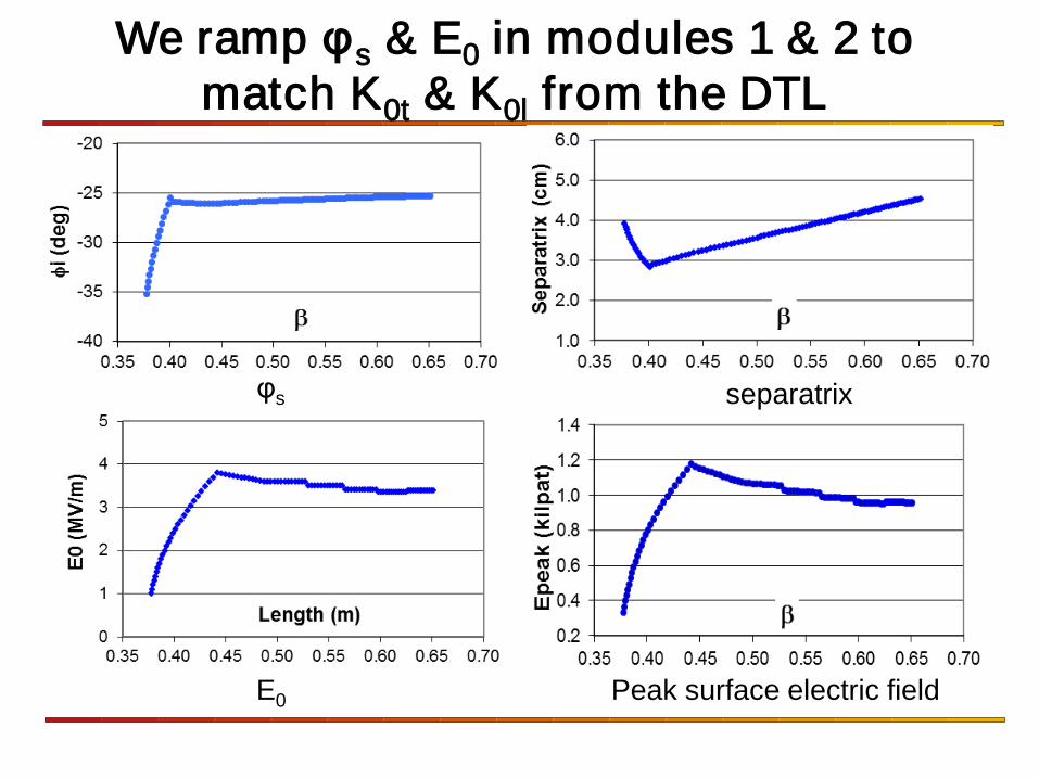
We ramp φs & E0 in modules 1 & 2 to match K0t & K0l from the DTL
E0 Peak surface electric field
φs separatrix
0.0 0.1 0.2 0.3 0.4 0.5 0.6 0.7β
0.25
0.35
0.45
0.55
0.65
P beam
/Pto
tal
DTL
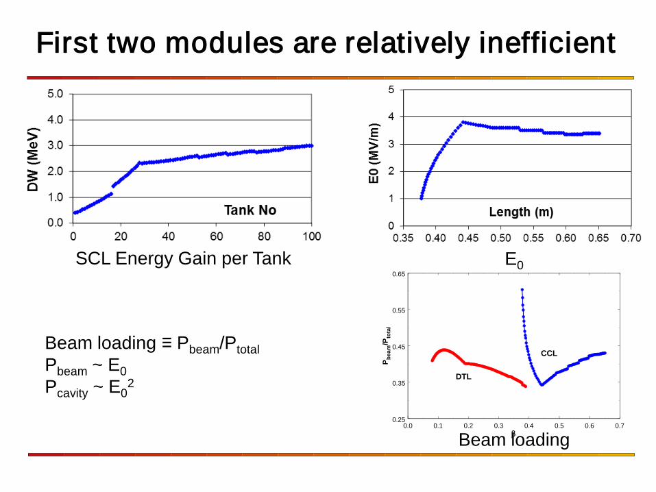
CCLBeam loading ≡ Pbeam/Ptotal Pbeam ~ E0 Pcavity ~ E0
2
Beam loading
First two modules are relatively inefficient
SCL Energy Gain per Tank E0
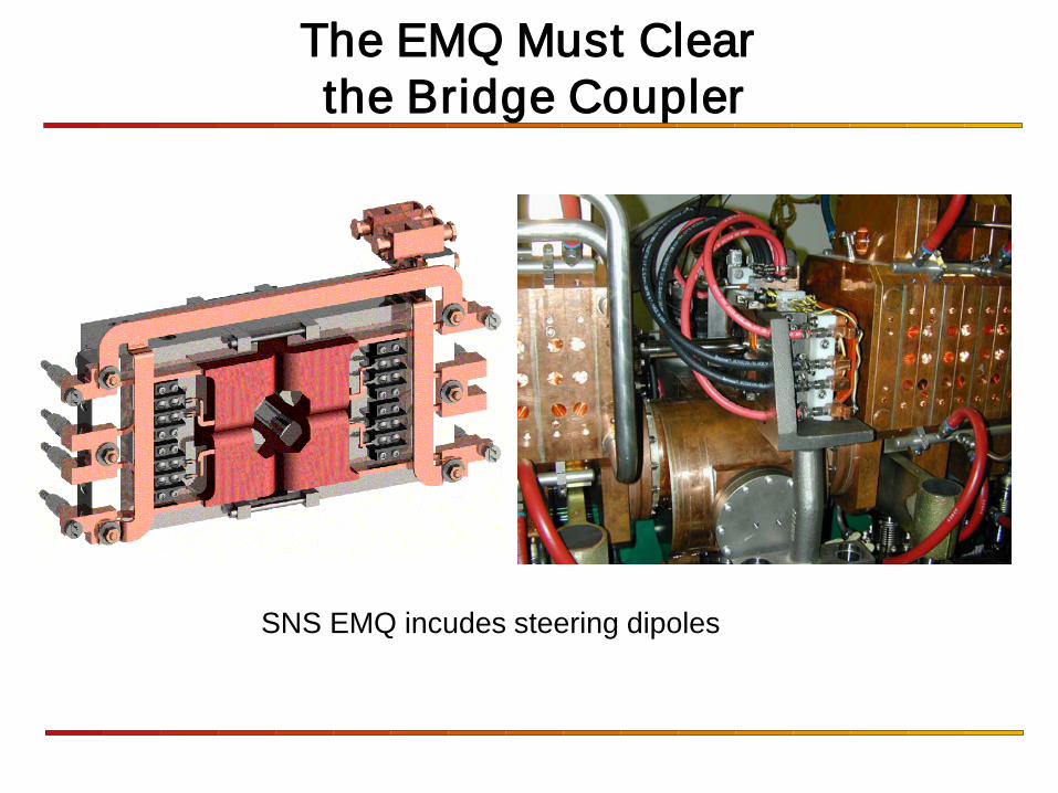
The EMQ Must Clear the Bridge Coupler
SNS EMQ incudes steering dipoles
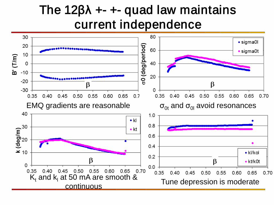
The 12βλ +- +- quad law maintains current independence
+-+-
EMQ gradients are reasonable σ0t and σ0l avoid resonances
Kt and kl at 50 mA are smooth & continuous Tune depression is moderate
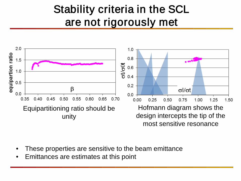
Stability criteria in the SCL are not rigorously met
Equipartitioning ratio should be unity
Hofmann diagram shows the design intercepts the tip of the
most sensitive resonance
• These properties are sensitive to the beam emittance • Emittances are estimates at this point
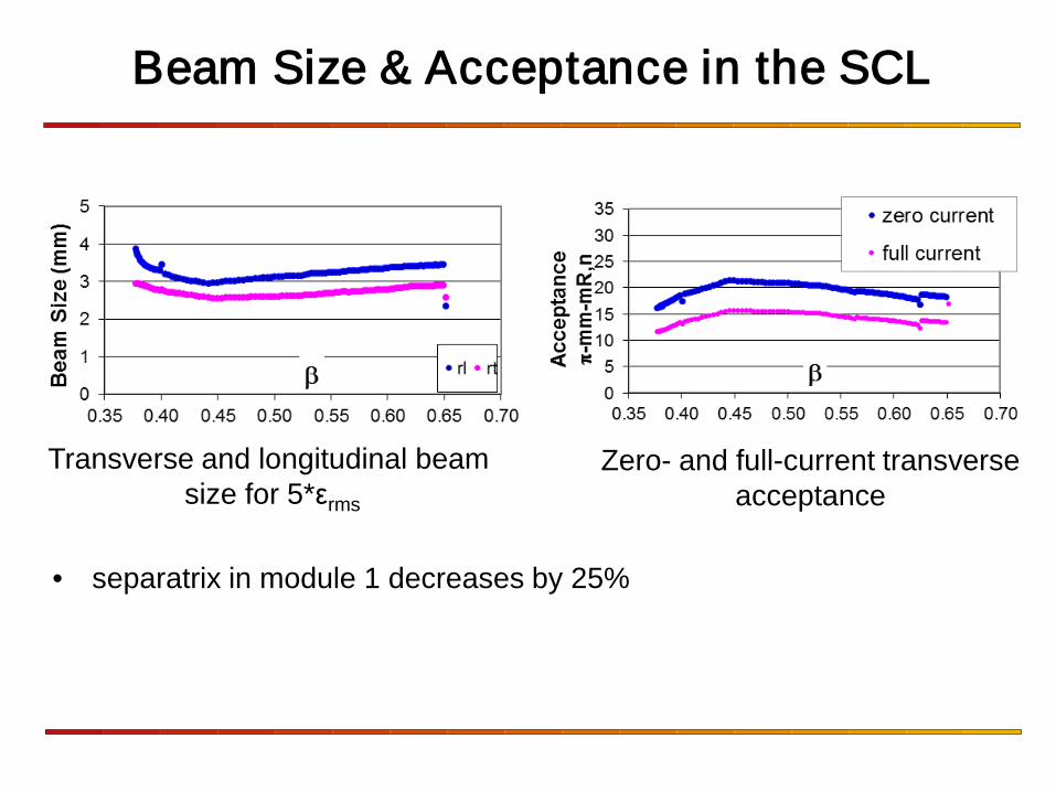
Beam Size & Acceptance in the SCL
Transverse and longitudinal beam size for 5*εrms
Zero- and full-current transverse acceptance
• separatrix in module 1 decreases by 25%
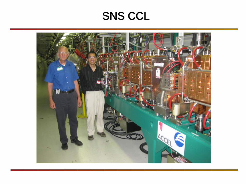
SNS CCL
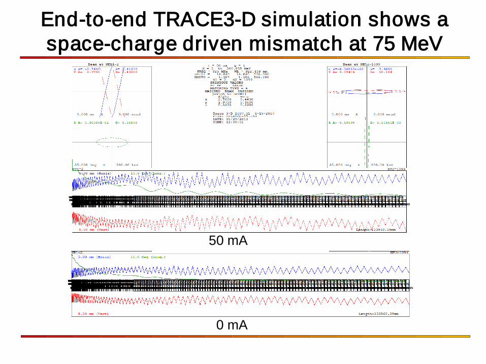
End-to-end TRACE3-D simulation shows a space-charge driven mismatch at 75 MeV
50 mA
0 mA
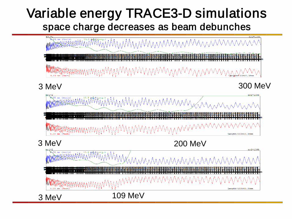
Variable energy TRACE3-D simulations space charge decreases as beam debunches
300 MeV
200 MeV
109 MeV
3 MeV
3 MeV
3 MeV
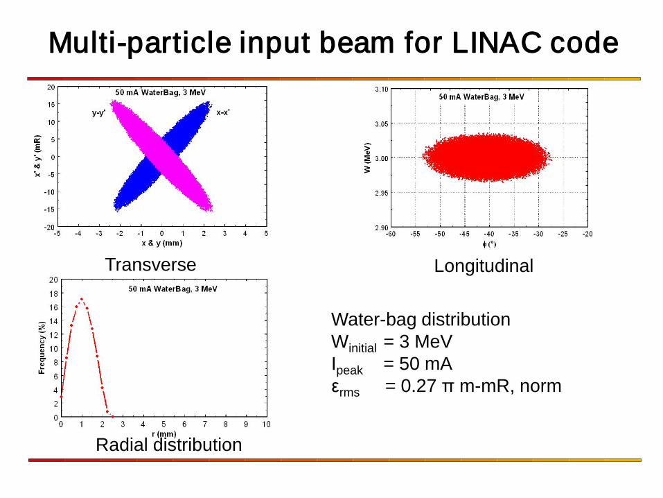
Multi-particle input beam for LINAC code
Transverse
Radial distribution
Longitudinal
Water-bag distribution Winitial = 3 MeV Ipeak = 50 mA εrms = 0.27 π m-mR, norm
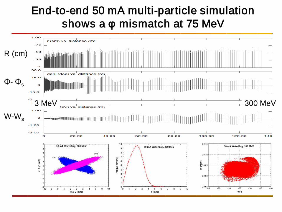
End-to-end 50 mA multi-particle simulation shows a φ mismatch at 75 MeV
R (cm) Φ- Φs W-Ws
3 MeV 300 MeV
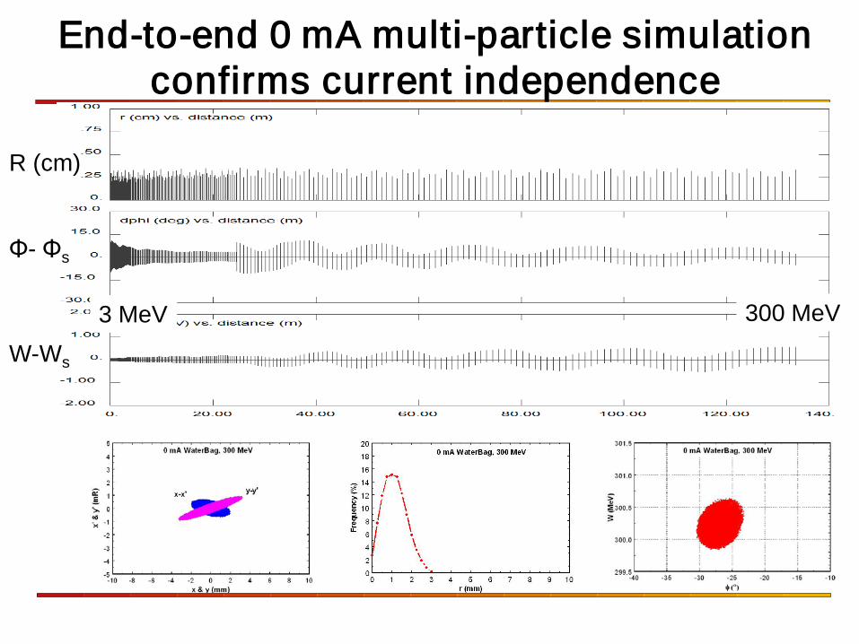
End-to-end 0 mA multi-particle simulation confirms current independence
0 mA
3 MeV 300 MeV
R (cm) Φ- Φs W-Ws
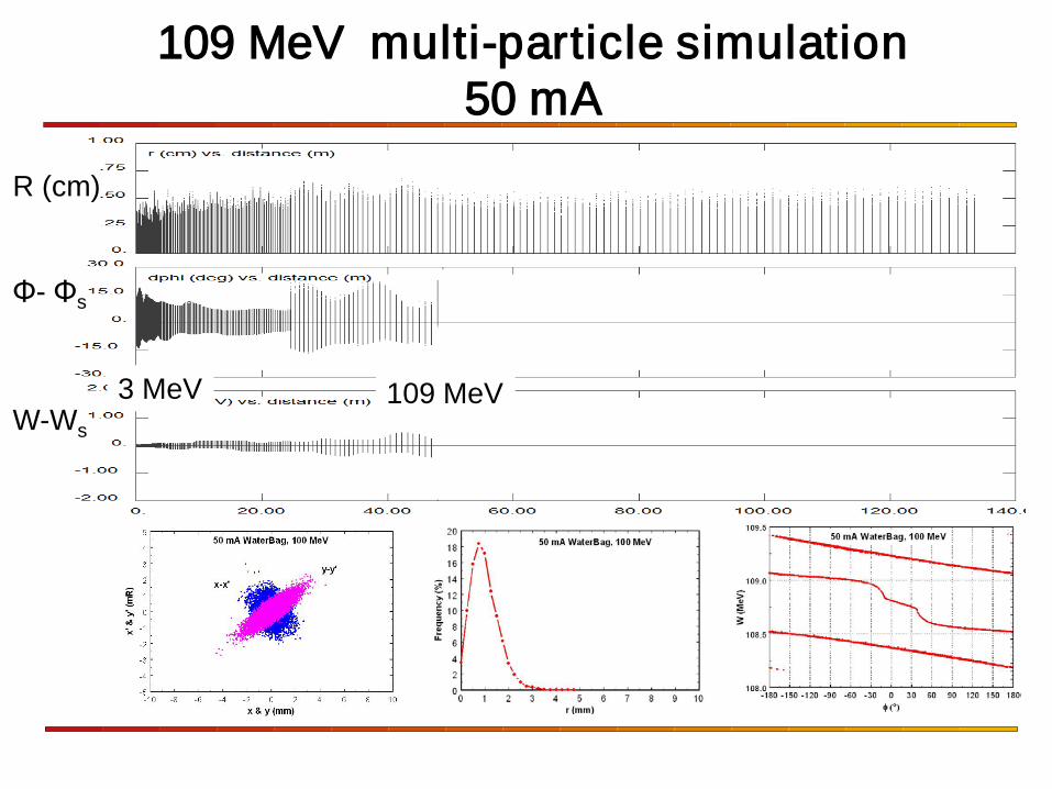
109 MeV multi-particle simulation 50 mA
R (cm) Φ- Φs W-Ws
3 MeV 109 MeV
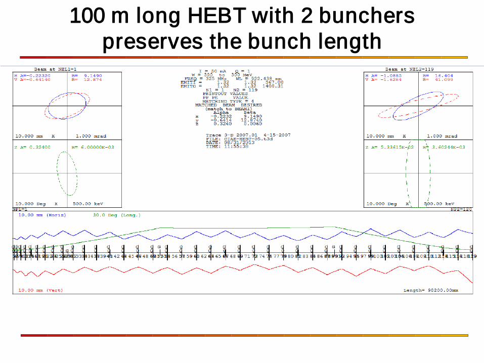
100 m long HEBT with 2 bunchers preserves the bunch length
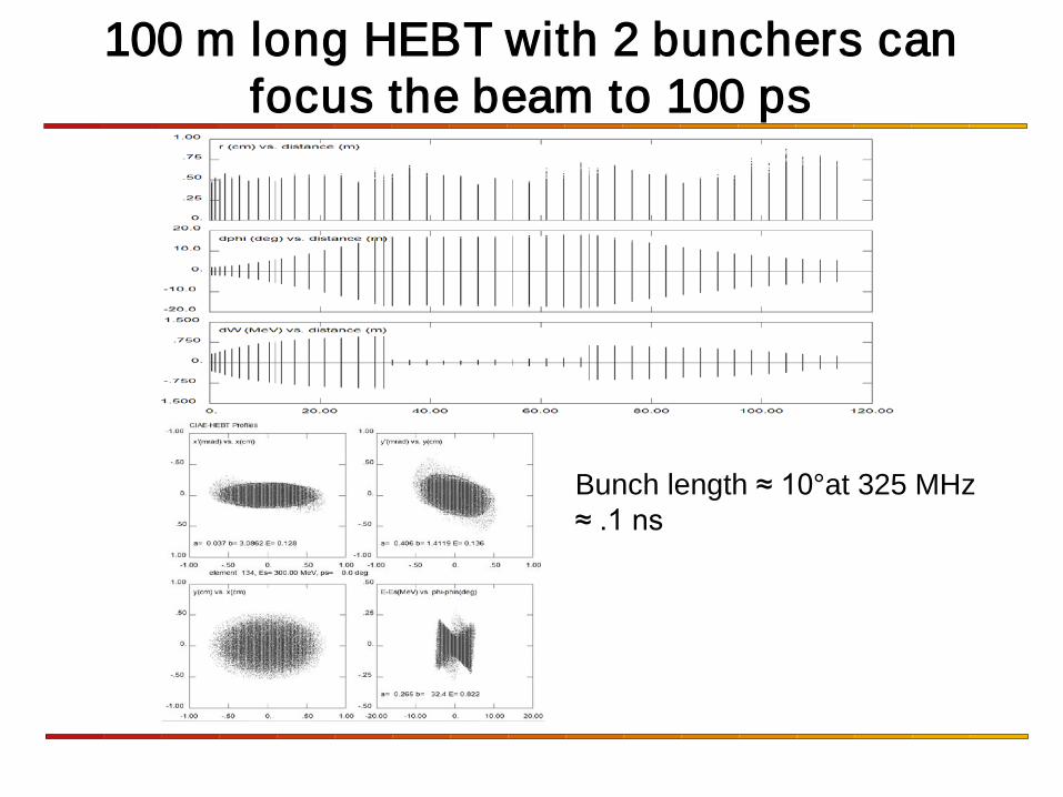
100 m long HEBT with 2 bunchers can focus the beam to 100 ps
Bunch length ≈ 10°at 325 MHz ≈ .1 ns