Embed Size (px)
Citation preview

EUROGRAPHICS Workshop on Graphics and Cultural Heritage (2016)C. E. Catalano and L. De Luca (Editors)
A Practical Reflectance Transformation Imaging Pipeline for
Surface Characterization in Cultural Heritage
I. Ciortan1, R. Pintus2, G. Marchioro1, C. Daffara1, A. Giachetti1, and E. Gobbetti2,
1University of Verona, Italy2CRS4, Visual Computing Group, Italy
Abstract
We present a practical acquisition and processing pipeline to characterize the surface structure of cultural heritage objects.
Using a free-form Reflectance Transformation Imaging (RTI) approach, we acquire multiple digital photographs of the stud-
ied object shot from a stationary camera. In each photograph, a light is freely positioned around the object in order to cover
a wide variety of illumination directions. Multiple reflective spheres and white Lambertian surfaces are added to the scene
to automatically recover light positions and to compensate for non-uniform illumination. An estimation of geometry and re-
flectance parameters (e.g., albedo, normals, polynomial texture maps coefficients) is then performed to locally characterize
surface properties. The resulting object description is stable and representative enough of surface features to reliably provide
a characterization of measured surfaces. We validate our approach by comparing RTI-acquired data with data acquired with a
high-resolution microprofilometer.
Categories and Subject Descriptors (according to ACM CCS): I.4.1 [Image processing and Computer Vision]: Digitization andImage Capture—Imaging Geometry
1. Introduction
The study of materials used in cultural objects is of extreme impor-tance for the understanding and preservation of Cultural Heritage(CH). Curators, restorers, conservators and conservation scientistsroutinely exploit information on materials to have the proper in-sights about the time and way an artwork has been made, the tech-niques used, the environmental conditions of preservation, the pre-vious conservation interventions, as well as to gather indicationsfor planning future interventions. Materials in CH are studied un-der many different angles, ranging from the acquisition of basicinformation, such as surface average color and roughness, to theanalysis of their molecular and elemental components. State-of-the-art study and conservation practices thus combine a wide va-riety of measurement probes and analytical techniques. Moreover,in order to study dynamic processes, such as the effects of aging,weathering, and restoration treatments, laboratory studies are oftenperformed on appropriately prepared samples and mock-ups.
Among the different material characterizations, the study of sur-face appearance, in terms of reflectance and geometric meso- andmicro-structure is of particular importance, since the vast majorityof the cultural information is conveyed through optical signals fromthe viewed artwork to the human vision system. Characterizing sur-face structure and appearance is thus paramount for a variety of CHapplications, from the assessment of the visual effects of restora-
tion treatments, to the high-fidelity virtual and physical replicationof cultural objects trough graphics and fabrication means.
Reflectance Transformation Imaging (RTI) [Woo78, MGW01,MVSL05], which derives material and geometry information fromphotographs of a fixed object under fixed camera position withvarying lighting conditions, are nowadays a de-facto standard in ap-pearance and geometry acquisition, due to their cost-effectivenessand flexibility. Light lies at the core of the artistic process, and illu-mination under multiple light conditions and directions is known tohave been used by artists throughout time in order to obtain a moreholistic representation when depicting a composition [PCC∗10].Correspondingly, in order to decipher an artistic technique or tounderstand the underlying information about an artifact, multi-lightimaging at raking angles [JMS∗14] provides a fair solution for thedocumentation, recording and decoding of CH objects [MMSL06].
Using RTI for surface characterization requires, however, to gobeyond purely qualitative measurements. While completely cali-brated setups, based on fixed domes, do exist, they have consider-able costs and limitations in terms of scalability to multiple objectsizes and achievable illumination configurations. The most practi-cal and flexible techniques are based, instead, on the combinationof freely moving lights with calibration objects to recover illumina-tion directions (see Sec. 2). However, due to the lack of uniformityin illumination intensity and direction, the results obtained with thissimple setup may vary widely between acquisitions, and may be not
c© 2016 The Author(s)Eurographics Proceedings c© 2016 The Eurographics Association.

I. Ciortan et al. / Surface characterization pipeline
suitable for quantitative analyses, which include normal estimation,roughness or material segmentation/classification, and monitoringover time. Exploitation of RTI data is thus limited.
Our approach. We introduce a simple and effective pipeline for theacquisition of geometry or visual appearance of cultural heritageobjects in the case of near-light condition and spatially varying illu-mination. Our setup consists of a DSLR camera, a hand held light,and several calibration target, i.e., a set of glossy dark spheres and awhite background (see Sec. 3). The algorithm takes an image stackcontaining multiple photos taken while light is projected from dif-ferent directions. In the calibration step the images are undistorted.Then, the pipeline exploits sphere targets to cope with a near-lightcondition, where the parallel ray assumption is violated and a per-pixel light direction is estimated. The white target helps to deal witha non-point and non-uniform light, by balancing the scene irradi-ance without explicitly requiring the light source position in spaceto correct the light intensity as a function of the inverse squareddistance, not to mention its more complex form factor (see Sec. 3).After that a corrected scene radiance is taken per-pixel in the formof an appearance profile [KN06]. An estimation of geometry andeventually reflectance parameters (e.g., albedo, normals, polyno-mial texture maps coefficients) is then performed to locally charac-terize surface and appearance properties. The setup and approachhave been validated by comparing our results with those obtainedwith a high-resolution laser microprofilometer.
Contribution. While not all the techniques presented in this workare novel in themselves, their elaboration and combination providea significant step towards a practical quantitative analysis usingsimple and low-cost uncalibrated acquisition strategies. We intro-duce, in particular, a setup and processing strategy that can copewith the effects of non-point lights, spatially varying illumination,and variable light distance, and we demonstrate the effectiveness ofthe approach even in challenging situations, such as damaged coinsand silver samples used for restoration studies.
Advantages and limitations. Our approach is designed with theidea of being cost-effective, flexible, and simple to use. It offers abetter reliability than current free-form approaches, while not re-quiring a fixed geometry, such as domes or robotic acquisitions,and/or complex calibration procedures. Since a single movablelamp is used, it is also easier and less costly than with multi-lightsetups to extend it to a multi- or hyper-spectral capture, since thiscould be achieved by just using narrow band illuminations or Liq-uid Crystal Tunable Filters (LCTF) in front of a monochromaticcamera. The results presented here are currently limited to the cap-ture of geometry and appearance by measuring low-frequency com-ponents of BRDFs, and must me extended to fully recover appear-ances of surfaces with complex reflectivity. This is, however, or-thogonal to the approach presented in this paper.
2. Related work
Measurement of surface properties from multi-light imaging is awide research subject. In the following, we provide an analysis ofthe most closely related approaches. For more details, we refer thereader to established surveys in digital material modeling [DRS10]and geometry and reflectance acquisition [AG15, WK15].
RTI setups. RTI transforms a high amount of visual information(2D image sets) into 2.5D multi-layer representations [DJB13],which include surface attributes such as gradient, local curvature,normal, and albedo [Mac15]. A wide variety of RTI acquisition se-tups exist, ranging from low-cost and transportable kits [CHI16],to different sizes of fixed light domes [CHI16, SSWK13, Ham15].Recently, some dome solutions have been presented that use bothvisible and invisible light wavelengths [LG14, Leu15]. Our setupis both low cost, simple to implement, and provides an easy cap-ture procedure. It is not a fixed light setup and allows a more flex-ible choice of number and position of the light sources, which isvery important when dealing with non-Lambertian, shiny materials.Moreover, it is easy to extend the presented pipeline to the multi-or hyper-spectral domain at a much lower cost than multiple-lightsetups.
Coping with non-ideal lighting. While dome solutions allow forpre-calibration, and thus more reliable data, the main problem inclassic RTI approaches with freely movable lights is that they gen-erally rely on some simple and limiting assumptions about lightingand materials. The most common assumption is a Lambertian ma-terial under uniform lighting generated by an infinite distance lightsource (parallel rays). The computation of surface attributes is thenprone to errors due to this simplistic model. For this reason, Xieet al. [XDW15] proposed a photometric stereo method that uses lo-cal/global mesh deformation approach to solve the non-linear prob-lem of PS with near point lighting. Rather than computing only sur-face orientation, they rely also on the computation of surface pointposition, which is a well-known problem in the case of surface dis-continuities or self and cast shadows. Moreover, although they takeinto account the attenuation of luminance due to the distance be-tween surface points and light source, they consider a Lambertianmaterial. Similarly, Ahmad et al. [ASSS14] developed a new pro-cedure to allow dynamic calibration of per-pixel light vectors asan object moves in the field of view. Unfortunately they also relyon Lambertian diffused maxima region. A more controlled, generalcalibration method that does not depend on Lambertian assump-tion has been presented recently by Xie et al. [XSJ∗15]. They cal-ibrate a LED-based system to take into account near-field light-ing and the dependency of surface irradiance on the light distance.They show acquisition of opaque and specular objects. However,their approach is strongly dependent on the model of LED radi-ance distribution, which is not uniform but isotropic. In a simi-lar manner Ukida et al. [UTSY15] developed an hybrid method(stereo plus photometric stereo) tailored on a illumination modelof a linear light source. Conversely, some other advanced meth-ods were proposed by Mecca et al. [MRC15b, MRC15a]; they arebased on a more complex mathematical formulation that exploitspartial differential irradiance equation ratios to deal with all thementioned highly non-linear physical factors being involved in theimage acquisition process. They model the material as a combina-tion of a diffuse Lambertian and a specular Blinn-Phong compo-nents. However the deformation of their results are still large fornon-Lambertian objects and the computational time of that morecomplex algorithm has been tested only with small images. Gi-achetti et al. [GDR∗15], similarly to us, instead of tackling thecomplex problem of recovering light positions and form factors,directly reduce the inhomogeneity of lighting using a calibration
c© 2016 The Author(s)Eurographics Proceedings c© 2016 The Eurographics Association.

I. Ciortan et al. / Surface characterization pipeline
Figure 1: Surface acquisition and characterization pipeline. Objects are acquired with a pre-calibrated camera and moving lights. Cal-
ibration objects added to the scene to automatically recover light positions and to compensate for non-uniform illumination. The resulting
pipeline computes surface features usable for a variety of applications.
plane with constant reflectivity. Their work, however, is limited toflattening the estimated lighting profile to emulate a purely direc-tional lighting, while we extend the proposed light correction ap-proach to a true per-pixel illumination correction accounting forper-pixel light direction and intensity,
From image stacks to parametric representations, There arevarious models for fitting the reflectance distribution data ob-tained with RTI acquisition and this paper focuses on polynomialbased interpolation (such as the seminal work of Malzbender etal. [MGW01]). As explained in Drew et al. [DHOMH12], polyno-mial approximation improves Lambertian Photometric Stereo (PS)by solving a higher order polynomial and, coupled with a dedi-cated reflectance model, allows for more realistic reproduction ofthe material’s radiance. The biquadratic function in typical poly-nomial approximations can be solved with linear regression byminimizing the least-squares error or obtaining more robust re-sults by trimming the outliers with least median squares method(LS) [RL05, ZD14, DHOMH12]. The regression outputs a set of 6coefficients for each pixel in the image dataset, that can be treatedas six spatial maps with the same spatial resolution as the orig-inal images, but with a reduced resolution in the angular spacedue to the n image-to-6 approximation [Mac15]. Here we use atrimmed LS [RL05] based on a simple and fast outlier diagnosticstrategy. It proves to be efficient even with the considerable amountof black noise and highlights caused by very low diffuse albedoand a high shininess of tested materials. A similar strategy can beapplied as well on other fitting functions like Hemispherical Har-monics (HSH) or higher order polynomials [GKPB04, ZD14] thatcould be easily added to our framework.
Material classification and descriptors Previous attempts havebeen made in the direction of material classification based on thefitted coefficients, e.g. HSH [WGSD09], PTM [GDR∗15] and PS[TGVG12] coefficients. In cited papers, pointwise reflectance pa-rameters are used to characterize the materials and segment differ-ent regions of a planar surface by means of clustering algorithms.
This approach has clear limits due to the difficulty in light calibra-tion, the dependency of the reflectance on local geometry, and othercomplex factors Our idea is to try to overcome these limits using asmart calibration approach.
3. Method
The basic idea behind the presented pipeline is to avoid the neces-sity of using complex calibrated light setups to have a real controlof the reflectance estimation, and to avoid either the large errors inthe reflectance parameters estimation due to light inhomogeneitytypical of freehand/highlight RTI capture. This is obtained using acapture setup with multiple reflective spheres and a planar whiteLambertian target. We propose to pre-calibrate the raw input databefore parameter fitting in order to treat each pixel as if we had anideal constant illumination intensity coming from a known ray di-rection. We do so by interpolating the light direction over the wholeimage and using white calibration patches to estimate local illumi-nation intensity at each pixel location. The setup can be easily usedin lab environments to acquire a wide range of objects (paintings,bas-reliefs, coins, etc.), but it could be even applied in outdoor ac-quisitions provided the proper positioning of calibration targets.
An overview of the proposed acquisition and processing pipelineis presented in Fig. 1. Before the acquisition, we have already (andonce) calibrated the internal characteristics of the camera, i.e., theradiometric response and the lens parameters. The acquisition setupincludes some reflective spheres, a white planar frame as back-ground, an hand-held light (freely moved by the user), and the ob-ject being captured. The white planar frame can be substituted withany kind of material with constant reflectance in the frequency bandused for illumination.
The capture process outputs an image stack, which is semi-automatically annotated to find the position of the spheres and tosegment the white background parts not cluttered by the object.These three inputs (camera internal parameters, image stack, and
c© 2016 The Author(s)Eurographics Proceedings c© 2016 The Eurographics Association.

I. Ciortan et al. / Surface characterization pipeline
(a) Setup (b) Scene (c) Annotation
Figure 2: Acquisition and annotation. (a) The acquisition setup composed of the stationary DSLR digital camera, the hand-held light source
and the CH targets arranged horizontally on a white background together with the four black reflective spheres. (b) Acquired scene. (c) User
interface for the annotation of reflective spheres and frame regions.
annotation) are used by the algorithm to perform a series of finecalibrations on images, light and camera. After that, each pixel isassociated with a calibrated reflectance profile, coupled with cal-ibrated light parameters; those are used to perform a reflectancefunction fitting in order to extract an objective lower dimensionalrepresentation described by a small number of coefficients. Thesefeature maps might be employed in a variety of applications, suchas surface reconstruction, object classification and recognition, vir-tual rendering/re-lighting, 3D printing and so forth. In the follow-ing, we describe in more details the various pipeline steps.
3.1. Camera calibration
Reflectance Transformation Imaging uses measurements of irradi-ance on the camera sensor to extract photometric and geometricinformation about the viewed scene. For this reason, we calibratethe camera both in terms of radiometric response and geometricalbehavior. The radiometric calibration aims at coping with the non-ideal, non-linear response of the camera sensor, and is obtained byphotographing a target under different exposures and computingparameters that transform the irradiance signal so that the measuredbrightness value will be linearly proportional to the amount of pho-tons hitting the sensor [GN04, Yor16]. We also take into accountthe geometrical behavior of the lens by calibrating the intrinsic pa-rameters of the camera [GoCMM16]. This will be used to removethe radial distortion from the input image stack.
3.2. Acquisition
The acquisition setup consists in a camera, a hand-held light, somecalibration targets (a white planar frame and four glossy spheres)and the object under study, which is assumed to be approximatelyflat. In fig. 2(b) we present the scene viewed by the camera, whichcontains four dark glossy spheres and a white diffuse planar target,on which we positioned six metallic objects being acquired. Dur-ing the acquisition, for each image the user changes the position ofthe light, and he tries to uniformly sample the direction across thehemisphere above the scene 2(a). A uniform sampling will assure awell mathematically conditioned light matrix and reduce the com-putation errors during the reflectance function fitting [KH14]. Apart
from that, we don’t have any particular constraints on the light formfactor (we do not rely on a point light source approximation), norwe force the user to strictly remain at the same distance from thescene to avoid variation of light intensity. Moreover, since we avoidthe common parallel rays assumption (or, far light condition), theuser can remain close to the object; this will increase the averagescene irradiance, decrease the exposure time per image, and thenspeed-up the entire capturing process. Without loss of generality,in all our experiments the ambient light is completely negligible.If that is not the case, many methods can robustly deal with thepresence of ambient light, even if its intensity is many times theilluminance of the directional light component [AP14].
3.3. Annotation and calibration
We propose a semi-automatic, simple, and fast calibration pipeline,in order to extract reliable object surface information. It consists intwo main steps, i.e., light direction and intensity calibration. Us-ing a custom software, we are able to estimate the light directionfrom the sphere highlight positions, and we assume that the lightdirection at each object point is well approximated by a linear inter-polation of the estimated values, as shown in [GDR∗15]. The userannotates the region of interest (ROI) of each sphere (see fig. 2(c).Then the ball position, the highlight position and the derived lightdirection associated to the centers of the spheres are estimated. Thelight direction for each pixel is computed by linear interpolation ofthose known directions. Now that we have the light direction foreach pixel, we need to compute and calibrate the spatially vary-ing light intensity. We exploit the white planar target, since we canmake some reliable assumptions about its Bidirectional ReflectanceDistribution Function (BRDF), albedo (ρ) and normal (n) values inthe viewer-oriented coordinate system. First of all, it is a Lamber-tian diffuser, so the reflected radiance will be:
Lr =ρ
π
∫ω
Li (θi,φi)cosθidωi (1)
Whatever is the nature of our light source, the previous calibrationof light directions allows us to consider a per-pixel collimated illu-mination, and the resulting simplified double-delta representation
c© 2016 The Author(s)Eurographics Proceedings c© 2016 The Eurographics Association.

I. Ciortan et al. / Surface characterization pipeline
(a) Original (b) Calibrated (c) Interpolated γ−1
(d) Original vs. Calibrated Profile
Figure 3: Light intensity calibration. In the top row, the original
image corresponding to light #6, its calibrated version and the in-
terpolated correction factor. In the bottom, two original (orange)
and calibrated (blue) appearance profiles of the pixels indicated by
the red and green crosses in the top image. Images sorted by angle
with the white calibration plane normal.
of the source incoming radiance [HS79]:
Li (θi,φi) = E0δ(cosθi − cosθ0)δ(φi −φ0) (2)
E0 is the irradiance produced by a collimated source on a surfaceoriented orthogonally to the direction (θ0,φ0), and (θ0,φ0) is theper-pixel known calibrated light direction. E0 must be constant andequal to a reference white value (ρ ≤ 1) for all the pixels in thewhite diffuse target. However, this is not true due to the spatiallyvarying nature of the light. For this reason, given a pixel (u,v) inthe diffuse target, and L̃r (u,v) the corresponding real measured ra-diance, the value of E0 will be:
E0 (u,v) =πL̃r (u,v)
ρcosθ0(3)
Note that we know the value of cosθ0 since we know the illumina-tion direction computed by interpolation from the directions recov-ered from sphere highlights, and we can recover the true white pla-nar target normal, which is approximately collinear with the view-ing direction, i.e., n = (0,0,1)T , from the known spherical targetsizes and positions in the image. At this point, we can easily findthe new calibrated pixel value Lr (u,v) for the white target regionby computing L̃r (u,v)γ(u,v), where γ(u,v) = E0 (u,v)
−1. Usingthis value instead of the original one for each of the acquired im-ages produces a calibrated appearance profile that is independent ofeffects such as near-light and non-uniformity of lamp illumination.
Now that we are able to retrieve the calibrated pixel value for thewhite region, we need to find a procedure to apply the same process
to the rest of the image, and in particular to the objects of interest.Given a sparse sampling of light intensity, we assume that its vari-ation in the image space is not a high frequency signal, but it canbe well approximated by smooth function. Moreover, we assumethat objects are thin and flat, thus approximately at a small distancefrom the plane defined by the white diffuse target. This makes a cu-bic, plane-based fitted signal still valid for the object points. Froma practical point of view, we need to segment and consider the setof pixels in the white region that are not in shadow, which are usedto compute the known values of γ. Then, in a completely automaticway, the algorithm computes the values of γ for the unknown pixelsby fitting a cubic polynomial. The final pixel values are obtained bypixel-wise multiplication of the γ(u,v) field by the measured imageL̃r (u,v). Fig. 3 shows the effect of light intensity calibration on oneof the original image in the input stack. We obtained the calibratedimage (Fig. 3(b)) by multiplying the original image (Fig. 3(a) withthe interpolated γ function rescaled to the unit interval to make itmore readable (Fig. 3(c)). The effect of light intensity correctionis pretty evident across all the image, and, in particular, it is veryclear in the upper left corner. There the original image is very darkmostly due to the combination of spatially-varying light (spot ef-fect), and the distance from the light source (near- and point-lighteffect). Since for each acquisition the light is in a different positionwith respect to the scene, deviations across images with respect tothe constant illumination assumption can be dramatic.
Since this calibration takes into account radiometric nature ofboth the image-forming system and the known targets, the calibra-tion of light intensity compensates the spatially varying behaviorkeeping reflectance values photometrically consistent across all theinput image stack. The result of the entire calibration procedure isa set of corrected reflectance appearance profiles (calibrated im-age stack), and a set of light coefficients to retrieve the per-imageand per-pixel light directions. The effect of calibration is evidentin Fig. 3(d), where we present the appearance profile data of thetwo pixels marked with the red (white target) and green (sample)crosses in Fig. 3(a) and Fig. 3(b). We can see that uncalibrated ap-pearance profiles look extremely jaggy due to unwanted lightingeffects, and would lead to noticeable difficulties and errors in sur-face and reflectance parameters estimation.
Figure 4: Enhancement. We compare the original picture (left)
with two different kinds of enhanced visualization of the captured
model, i.e., unsharp masking applied to the normal field (center)
and to the full set of PTM coefficients (right). Note how enhance-
ment makes severely degraded details readable.
c© 2016 The Author(s)Eurographics Proceedings c© 2016 The Eurographics Association.

I. Ciortan et al. / Surface characterization pipeline
3.4. Surface characterization
The calibrated appearance profiles can be used for extracting stableparameters characterizing the object surface. Quantitatively speak-ing, the profile signal is a sum of several contributions, rangingfrom the diffuse behavior of the material to its specular component.In this paper, instead of modeling the high frequency modeling ofthe material Bidirectional Reflectance Distribution Function, weexplore the possibility of extracting meaningful information fromthe low frequency part, which consists in all the Lambertian andnon-Lambertian diffuse components [IA14].As discussed in Sec. 4,this part of the signal is reliable enough even in the case of highlyspecular metallic objects. The low frequency assumption allows usto approximate per-pixel reflectance profiles by low-degree poly-nomial interpolation [MGW01]. We employ the polynomial repre-sentation presented by Drew et al. [DHOMH12], which uses 6 co-efficients (a,b,c,d,e, f ) to relate the light direction (lx, ly, lz) withthe measured, calibrated reflectance Lr:
Lr = [a,b,c,d,e, f ][
lx, ly, lz, l2x , lxly,1
]T
(4)
The first three coefficients (a,b,c) model the pure Lambertian partof the reflectance, the coefficient f models the ambient light term,while the two coefficients (d,e) take into account other diffuse andlow-frequency non-diffuse surface behavior (e.g., non-Lambertiandiffuse signals or interreflections).
Given a profile, in order to remove outliers due to shad-ows and high-frequency reflections, we apply Trimmed LeastSquares [RL05]) to fit the data with the equation 4. For each pixel,we estimate the 6-dimensional vector of polynomial coefficients,which we consider our lower dimensional representation of the ap-pearance profile. This way to express per-pixel data is very usefulfor different kind of applications, e.g., it is possible to directly usethe coefficients as a 6D texture, and to compute descriptors fromit for classification and recognition purposes [BCDG13,GDR∗15].Here we focus on the reconstruction of normal and albedo of thesurface from the coefficients. The first three coefficients (a,b,c)represents the albedo-scaled normal vector, so its magnitude is thealbedo, while the direction is the normal. Computing the normalswith a polynomial interpolation rather than the classic photometricstereo 3-dimensional model takes into account not only the Lam-bertian component of the material but a more wide diffuse non-Lambertian behavior, resulting in a more relaxed set of assump-tions [IA14]. Moreover, having a precise and reliable estimation ofthose surface attributes is extremely important to obtain informa-tion about surface behavior (e.g., roughness [Kay15]), and, by in-tegrating normals, to compute a 3D model as well [BB15]. We willshow in the section 4 how the proposed, simple calibration pipelineprovides more stable quantitative results with respect to standardfree-form RTI approaches, by producing repeatable and reliableoutcomes that are comparable with other common and establishedmeasuring systems (i.e., the optical microprofilometer). Moreover,by suitably processing the coefficients, it is possible to render theobjects in order to enhance particular aspects of them, making themmore readable. An example is presented in Fig. 4, where a severelydamaged coin is made more readable by enhancing local variations.Note how, by unsharp masking the full PTM coefficients, we obtaina more readable result than just unsharp masking the normal.
(a) It. Bronzital 10c (b) It. Copper 10c (c) Roman Quad.
(d) Silver sample #15
(e) Silver sample #22
(f) Silver sample #28
(g) Silver sample #30
Figure 5: Samples. Photos of the metallic samples used to test the
proposed approach: (a) an Italian Bronzital 10c coin; (b) a severely
degraded Italian copper 10c coin; (c) a bronze roman coin; one
polished silver with a partial coating treatment(d); three chiseled
silver plates, i.e., #22(e), #28(f) and #30(g).
4. Results
The pipeline described in this paper has been implemented usingwidely available devices, including a LED lamp and a DSLR cam-era. We present in this work the results obtained in the reconstruc-tion and analysis of some metallic samples, which, due to their
c© 2016 The Author(s)Eurographics Proceedings c© 2016 The Eurographics Association.

I. Ciortan et al. / Surface characterization pipeline
sometimes very high reflectivity and low diffusivity, present a dif-ficult test case for RTI approaches.
4.1. Samples
We tested our system on a variety of samples and cultural objects.We present in this paper results obtained on laboratory-createdmetallic plates, as well as on ancient and antique coins (see Fig. 5).
The plates, custom made to study metal and metal treatment be-havior, are made of 95% silver and 5% copper. They have a thick-ness of 1mm and a size of 7cm by 2.5cm. Three of the tested sam-ples (sample 22, 28, 30) were chiseled, in order to emulate the ap-pearance of cultural objects, while the fourth one (sample 15) ispolished and partially coated with nitrocellulose and wax. The chis-eled samples are used in this paper to test the geometric accuracyand repeatability of our pipeline, while the polished one is used totest the repeatability of surface characterization.
The coins are a small bronze roman coin (quadrans) dated 9 BC.and damaged by scratches, and two 10 cent Italian coins. One ex-emplar, dated 1931 is made of copper and is severely degraded,while the second exemplar, dated 1939, is made of a special alloywith nickel called Bronzital, which has been used to improve cor-rosion resistance.
4.2. Camera calibration
The digital camera used for the experiment is a DSLR Nikon D810with CMOS sensor (36x24mm, spatial resolution of 36MP for thefull format image area). The lens attached was a full resolution AF-S FX Nikkor 50mm f/1.8G. The sensor of the digital camera waschecked for linearity, by taking images with different exposures,from very dark to very bright and then plotting the brightness of theimages as a function of exposure. The camera was geometricallycalibrated by computing intrinsic parameters and undistorting theimages before feeding them to the RTI pipeline. We employed amodel with two radial and two tangential distortion coefficients.We used the GML Camera Calibration Toolbox [Vel16], but anyother calibration tool can be used as well to perform this task.
4.3. Acquisition setup and protocol
The acquisition scene was set-up horizontally and the digital cam-era was placed on top at a distance of approximately 95cm, on aperpendicular direction to the image plane, as shown in Fig.2(a).The Ground Sampling Distance when using the 50 mm lens was0.009 cm/pixel. The metallic samples were arranged on a whitepaper frame. Four reflective black spheres were included so as toenable light direction estimation from the freely moved hand-heldlight source. A Spectralon target was included in the scene as a per-fect white diffuser. The light source used for the experiment was awhite LED (color temperature 6500K) for visible (VIS) photog-raphy, with very limited emission in the infrared (IR). The digitalcamera was remote controlled. The acquisition configuration wasset as follows: ISO 32, aperture f8, shutter speed 0.8s, custom whitebalance and manual focus. The samples were acquired in two ses-sions. During each acquisition, a virtual light dome was createdby manually moving the light source around the samples, from 12
azimuth locations with 4 corresponding elevation points and a fi-nal acquisition from the top, giving a total of 49 images which cantranslate into 49 light directions. All images were shot in RAW for-mat.
(a) Italian Bronzital 10c coin
(b) Roman Quadrans
Figure 6: Normal deviation in two different acquisitions. For each
coin, the left image maps the angular deviation of normals recon-
structed from two different acquisitions without light calibration,
while the right image presents the result obtained when light direc-
tion and intensity are corrected per pixel.
(a) Without calibration
(b) With calibration
Figure 7: Unsupervised classification. Two class k-means cluster-
ing applied to two different acquisitions of the polished sample #15
(fig. 5(d)). The coated area is in red while the uncoated area is in
green. Without calibration we have 20% of classification similarity,
while we obtain a value of 99.5% by using the calibrated images.
This shows the drastically increased level of repeatability of the
proposed pipeline with respect to classic free-form RTI.
c© 2016 The Author(s)Eurographics Proceedings c© 2016 The Eurographics Association.

I. Ciortan et al. / Surface characterization pipeline
4.4. Repeatability and characterization
In order to test for repeatability, acquisitions of the same sampleswere repeated multiple times, and the PTM coefficients were recon-structed using a robust approach with trimming with and withoutlight intensity and direction calibration before parameter fitting.
As expected, light calibration sensibly improves acquisition,making it more predictable. Fig. 6 shows, for the Roman and Italiancoin samples, the deviation in the reconstructed normals acquiredtwice using the same number of lights and a similar illuminationpattern, controlled free hand. The median angular deviation of nor-mals decreases, when using calibration, from 1.86 to 1.17 degreesfor the Bronzital 10c coin and from 2.69 to 1.41 degrees for the Ro-man Quadrans. Much larger variations occur on the metallic plates,which have a larger extent and, therefore, suffer more of light inho-mogeneity.
The repeatability of the proposed approach is particularly impor-tant to obtain a stable surface characterization. As a representativeexample of material classification, we have performed two RTI ac-quisitions of a polished silver sample partially covered by a coating,see Fig. 5(d), and applied unsupervised classification to segment re-gions with or without coating. For each RTI sample, we compute a7-dimensional descriptor of a 30 pixels neighborhood. The descrip-tor is the average albedo value, to account for material color, plusthe 6 standard deviations of the polynomial coefficients, to accountfor the roughness of the sample surface.
Unsupervised classification is achieved by performing two-classk-means clustering. We measure the similarity of the classificationoutcomes obtained from the two different acquisitions, without andwith light calibration, see Fig. 7. The only difference between thetwo acquisitions of the same sample is the different lighting patterncaused by the free-form approach. The coated area is in red whilethe uncoated area is in green. In the absence of light calibration,the clustering outcome is unstable, as it has only a 20% overlap,while, by performing light calibration, we improve it up to 99.5%of pixels that have been assigned to the same class, showing thatwith our approach free-form RTI can be used for characterization.
4.5. Comparison with microprofilometer
In order to test the accuracy of shape capturing, we comparedour reconstruction with measures taken with an optical micropro-filometer based on conoscopic holography [SP85], which is capa-ble to take reliable and stable profilometric measurements down tothe scale of micron on different kinds of materials, reflective or dif-fusive. The microprofilometer is based on an Optimet conoscopicprobe mounted on sub-micrometric linear stages in order to scan aregion up to 30x30cm2 in one session. Different acquisition setupsare used to adapt the working range of the system to the deforma-tion of the various objects, with the surface data collected at dif-ferent spatial grid. Silver samples, which are highly reflective and”flat” surfaces (submillimetric deformation), were measured with atransversal resolution (XY grid) of 50 microns with a repeatability(Z heights) of 0.6 microns. Coins, which are less glossy surfaceswith deformation in the order of millimeters, were measured with atransversal resolution (XY grid) of 50 microns with a repeatability(Z heights) of 0.1 microns.
(a) Italian Bronzital 10c coin
(b) Italian Copper 10c coin
(c) Roman Quadrans
(d) sample 22
(e) sample 28
(f) sample 30
Figure 8: Registered normal maps. Color-coded normal maps ob-
tained with the RTI approach compared with microprofilometric
reference on the three coins surfaces and the three silver samples.
From left to right: uncalibrated RTI, calibrated RTI, ground truth
from microprofilometry.
For our comparison, we measured differences between normalmaps estimated from the RTI procedure with those derived by themicroprofilometric map. Since normals are very sensitive to highfrequency details, even the smallest errors are magnified, and nor-mals are, therefore, a very good indicator. It should be noted thatthe surface layers captured by different instrument may be slightlydifferent, and the direct comparison should be considered with caredue to the different levels of detail of the instruments and their dif-ferent sensitivity with respect to materials. However, a qualitativeand quantitative comparison of the normals can give a reasonable
c© 2016 The Author(s)Eurographics Proceedings c© 2016 The Eurographics Association.
I. Ciortan et al. / Surface characterization pipeline
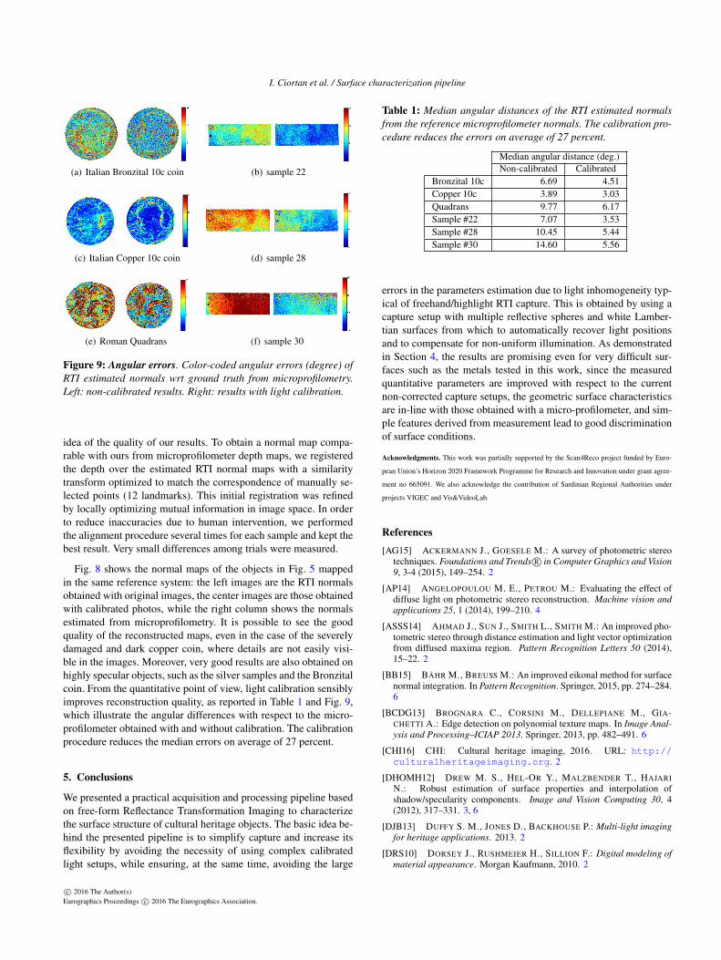
(a) Italian Bronzital 10c coin (b) sample 22
(c) Italian Copper 10c coin (d) sample 28
(e) Roman Quadrans (f) sample 30
Figure 9: Angular errors. Color-coded angular errors (degree) of
RTI estimated normals wrt ground truth from microprofilometry.
Left: non-calibrated results. Right: results with light calibration.
idea of the quality of our results. To obtain a normal map compa-rable with ours from microprofilometer depth maps, we registeredthe depth over the estimated RTI normal maps with a similaritytransform optimized to match the correspondence of manually se-lected points (12 landmarks). This initial registration was refinedby locally optimizing mutual information in image space. In orderto reduce inaccuracies due to human intervention, we performedthe alignment procedure several times for each sample and kept thebest result. Very small differences among trials were measured.
Fig. 8 shows the normal maps of the objects in Fig. 5 mappedin the same reference system: the left images are the RTI normalsobtained with original images, the center images are those obtainedwith calibrated photos, while the right column shows the normalsestimated from microprofilometry. It is possible to see the goodquality of the reconstructed maps, even in the case of the severelydamaged and dark copper coin, where details are not easily visi-ble in the images. Moreover, very good results are also obtained onhighly specular objects, such as the silver samples and the Bronzitalcoin. From the quantitative point of view, light calibration sensiblyimproves reconstruction quality, as reported in Table 1 and Fig. 9,which illustrate the angular differences with respect to the micro-profilometer obtained with and without calibration. The calibrationprocedure reduces the median errors on average of 27 percent.
5. Conclusions
We presented a practical acquisition and processing pipeline basedon free-form Reflectance Transformation Imaging to characterizethe surface structure of cultural heritage objects. The basic idea be-hind the presented pipeline is to simplify capture and increase itsflexibility by avoiding the necessity of using complex calibratedlight setups, while ensuring, at the same time, avoiding the large
Table 1: Median angular distances of the RTI estimated normals
from the reference microprofilometer normals. The calibration pro-
cedure reduces the errors on average of 27 percent.
Median angular distance (deg.)Non-calibrated Calibrated
Bronzital 10c 6.69 4.51Copper 10c 3.89 3.03Quadrans 9.77 6.17Sample #22 7.07 3.53Sample #28 10.45 5.44Sample #30 14.60 5.56
errors in the parameters estimation due to light inhomogeneity typ-ical of freehand/highlight RTI capture. This is obtained by using acapture setup with multiple reflective spheres and white Lamber-tian surfaces from which to automatically recover light positionsand to compensate for non-uniform illumination. As demonstratedin Section 4, the results are promising even for very difficult sur-faces such as the metals tested in this work, since the measuredquantitative parameters are improved with respect to the currentnon-corrected capture setups, the geometric surface characteristicsare in-line with those obtained with a micro-profilometer, and sim-ple features derived from measurement lead to good discriminationof surface conditions.
Acknowledgments. This work was partially supported by the Scan4Reco project funded by Euro-
pean Union’s Horizon 2020 Framework Programme for Research and Innovation under grant agree-
ment no 665091. We also acknowledge the contribution of Sardinian Regional Authorities under
projects VIGEC and Vis&VideoLab.
References
[AG15] ACKERMANN J., GOESELE M.: A survey of photometric stereotechniques. Foundations and Trends R© in Computer Graphics and Vision
9, 3-4 (2015), 149–254. 2
[AP14] ANGELOPOULOU M. E., PETROU M.: Evaluating the effect ofdiffuse light on photometric stereo reconstruction. Machine vision and
applications 25, 1 (2014), 199–210. 4
[ASSS14] AHMAD J., SUN J., SMITH L., SMITH M.: An improved pho-tometric stereo through distance estimation and light vector optimizationfrom diffused maxima region. Pattern Recognition Letters 50 (2014),15–22. 2
[BB15] BÄHR M., BREUSS M.: An improved eikonal method for surfacenormal integration. In Pattern Recognition. Springer, 2015, pp. 274–284.6
[BCDG13] BROGNARA C., CORSINI M., DELLEPIANE M., GIA-CHETTI A.: Edge detection on polynomial texture maps. In Image Anal-
ysis and Processing–ICIAP 2013. Springer, 2013, pp. 482–491. 6
[CHI16] CHI: Cultural heritage imaging, 2016. URL: http://culturalheritageimaging.org. 2
[DHOMH12] DREW M. S., HEL-OR Y., MALZBENDER T., HAJARI
N.: Robust estimation of surface properties and interpolation ofshadow/specularity components. Image and Vision Computing 30, 4(2012), 317–331. 3, 6
[DJB13] DUFFY S. M., JONES D., BACKHOUSE P.: Multi-light imaging
for heritage applications. 2013. 2
[DRS10] DORSEY J., RUSHMEIER H., SILLION F.: Digital modeling of
material appearance. Morgan Kaufmann, 2010. 2
c© 2016 The Author(s)Eurographics Proceedings c© 2016 The Eurographics Association.

I. Ciortan et al. / Surface characterization pipeline
[GDR∗15] GIACHETTI A., DAFFARA C., REGHELIN C., GOBBETTI E.,PINTUS R.: Light calibration and quality assessment methods for re-flectance transformation imaging applied to artworks’ analysis. In SPIE
Optical Metrology (2015), International Society for Optics and Photon-ics, pp. 95270B–95270B. 2, 3, 4, 6
[GKPB04] GAUTRON P., KRIVANEK J., PATTANAIK S. N., BOUA-TOUCH K.: A novel hemispherical basis for accurate and efficient ren-dering. Rendering Techniques 2004 (2004), 321–330. 3
[GN04] GROSSBERG M. D., NAYAR S. K.: Modeling the space of cam-era response functions. Pattern Analysis and Machine Intelligence, IEEE
Transactions on 26, 10 (2004), 1272–1282. 4
[GoCMM16] GRAPHICS, OF COMPUTATIONAL MATHEMATICS M.L. F., MOSCOW C.: Gml c++ camera calibration toolbox, 2016. URL:http://graphics.cs.msu.ru/en/node/909. 4
[Ham15] HAMEEUW H.: Mesopotamian clay cones in the ancient neareast collections of the royal museums of art and history. Bulletin van de
Koninklijke Musea voor Kunst en Geschiedenis 84 (2015), 5–48. 2
[HS79] HORN B. K., SJOBERG R. W.: Calculating the reflectance map.Applied optics 18, 11 (1979), 1770–1779. 5
[IA14] IKEHATA S., AIZAWA K.: Photometric stereo using constrainedbivariate regression for general isotropic surfaces. In Proceedings of the
IEEE Conference on Computer Vision and Pattern Recognition (2014),pp. 2179–2186. 6
[JMS∗14] JOHNSON C. R., MESSIER P., SETHARES W. A., KLEIN
A. G., BROWN C., DO A. H., KLAUSMEYER P., ABRY P., JAFFARD
S., WENDT H., ET AL.: Pursuing automated classification of historicphotographic papers from raking light images. Journal of the American
Institute for Conservation 53, 3 (2014), 159–170. 1
[Kay15] KAYA B.: Surface roughness inspection in milling operationswith photometric stereo and pnn. The International Journal of Advanced
Manufacturing Technology 81, 5-8 (2015), 1215–1222. 6
[KH14] KLAUDINY M., HILTON A.: Error analysis of photometricstereo with colour lights. Pattern Recognition Letters 48 (2014), 81–92.4
[KN06] KOPPAL S. J., NARASIMHAN S. G.: Clustering appearance forscene analysis. In Computer Vision and Pattern Recognition, 2006 IEEE
Computer Society Conference on (2006), vol. 2, IEEE, pp. 1323–1330.2
[Leu15] LEUVEN K.: Multispectral microdome, 2015. URL: https://portablelightdome.wordpress.com/2015/04/29/
rich-presents-the-new-multispectral-microdome/.2
[LG14] LIU C., GU J.: Discriminative illumination: Per-pixel classifi-cation of raw materials based on optimal projections of spectral brdf.Pattern Analysis and Machine Intelligence, IEEE Transactions on 36, 1(2014), 86–98. 2
[Mac15] MACDONALD L. W.: Realistic visualisation of cultural heritage
objects. PhD thesis, UCL (University College London), 2015. 2, 3
[MGW01] MALZBENDER T., GELB D., WOLTERS H.: Polynomial tex-ture maps. In Proceedings of the 28th annual conference on Computer
graphics and interactive techniques (2001), ACM, pp. 519–528. 1, 3, 6
[MMSL06] MUDGE M., MALZBENDER T., SCHROER C., LUM M.:New reflection transformation imaging methods for rock art andmultiple-viewpoint display. In VAST (2006), vol. 6, Citeseer, pp. 195–202. 1
[MRC15a] MECCA R., RODOLÀ E., CREMERS D.: Analysis of surfaceparametrizations for modern photometric stereo modeling. In The Inter-
national Conference on Quality Control by Artificial Vision 2015 (2015),International Society for Optics and Photonics, pp. 95341B–95341B. 2
[MRC15b] MECCA R., RODOLÀ E., CREMERS D.: Realistic photomet-ric stereo using partial differential irradiance equation ratios. Computers
& Graphics 51 (2015), 8–16. 2
[MVSL05] MUDGE M., VOUTAZ J.-P., SCHROER C., LUM M.: Reflec-tion transformation imaging and virtual representations of coins from thehospice of the grand st. bernard. In VAST (2005), vol. 2005, p. 6th. 1
[PCC∗10] PALMA G., CORSINI M., CIGNONI P., SCOPIGNO R.,MUDGE M.: Dynamic shading enhancement for reflectance transforma-tion imaging. Journal on Computing and Cultural Heritage (JOCCH) 3,2 (2010), 6. 1
[RL05] ROUSSEEUW P. J., LEROY A. M.: Robust regression and outlier
detection, vol. 589. John Wiley & Sons, 2005. 3, 6
[SP85] SIRAT G., PSALTIS D.: Conoscopic holography. Optics letters
10, 1 (1985), 4–6. 8
[SSWK13] SCHWARTZ C., SARLETTE R., WEINMANN M., KLEIN R.:Dome ii: A parallelized btf acquisition system. In Proceedings of the
Eurographics 2013 Workshop on Material Appearance Modeling: Issues
and Acquisition (2013), Eurographics Association, pp. 25–31. 2
[TGVG12] TINGDAHL D., GODAU C., VAN GOOL L.: Base materialsfor photometric stereo. In Computer Vision–ECCV 2012. Workshops and
Demonstrations (2012), Springer, pp. 350–359. 3
[UTSY15] UKIDA H., TANIMOTO Y., SANO T., YAMAMOTO H.: 3dshape and color estimation using linear light sources and cameras. InImaging Systems and Techniques (IST), 2015 IEEE International Con-
ference on (2015), IEEE, pp. 1–5. 2
[Vel16] VELIZHEV A.: Gml c++ camera calibration toolbox, 2016. URL:http://graphics.cs.msu.ru/en/node/909. 7
[WGSD09] WANG O., GUNAWARDANE P., SCHER S., DAVIS J.: Ma-terial classification using brdf slices. In Computer Vision and Pattern
Recognition, 2009. CVPR 2009. IEEE Conference on (2009), IEEE,pp. 2805–2811. 3
[WK15] WEINMANN M., KLEIN R.: Advances in geometry and re-flectance acquisition (course notes). In SIGGRAPH Asia 2015 Courses
(2015), ACM, p. 1. 2
[Woo78] WOODHAM R. J.: Photometric stereo. 1
[XDW15] XIE W., DAI C., WANG C. C.: Photometric stereo with nearpoint lighting: A solution by mesh deformation. In Computer Vision and
Pattern Recognition (CVPR), 2015 IEEE Conference on (2015), IEEE,pp. 4585–4593. 2
[XSJ∗15] XIE L., SONG Z., JIAO G., HUANG X., JIA K.: A practicalmeans for calibrating an led-based photometric stereo system. Optics
and Lasers in Engineering 64 (2015), 42–50. 2
[Yor16] YORK C. V. L. C. U. N.: Rascal - radiometric self cali-bration, 2016. URL: http://www1.cs.columbia.edu/CAVE/software/rascal/rrhome.php. 4
[ZD14] ZHANG M., DREW M. S.: Efficient robust image interpolationand surface properties using polynomial texture mapping. EURASIP
Journal on Image and Video Processing 2014, 1 (2014), 1–19. 3
c© 2016 The Author(s)Eurographics Proceedings c© 2016 The Eurographics Association.


![Competent cells formation and transformation of competent cells with DNA. BCH 462 [practical] 2 nd lab](https://img.pdfslide.us/doc/110x75/56649d8e5503460f94a765f1/competent-cells-formation-and-transformation-of-competent-cells-with-dna-bch.jpg)