Embed Size (px)
Citation preview
Rochester Institute of Technology Rochester Institute of Technology
RIT Scholar Works RIT Scholar Works
Theses
3-1-2014
A Portrayal of Biomechanics in Avian Flight A Portrayal of Biomechanics in Avian Flight
Kelly M. Kage
Follow this and additional works at: https://scholarworks.rit.edu/theses
Recommended Citation Recommended Citation Kage, Kelly M., "A Portrayal of Biomechanics in Avian Flight" (2014). Thesis. Rochester Institute of Technology. Accessed from
This Thesis is brought to you for free and open access by RIT Scholar Works. It has been accepted for inclusion in Theses by an authorized administrator of RIT Scholar Works. For more information, please contact [email protected].
ROCHESTER INSTITUTE OF TECHNOLOGY
A Thesis Submitted to the Faculty of
The College of Health Sciences and Technology
Medical Illustration
In Candidacy for the Degree of
MASTER OF FINE ARTS
A PORTRAYAL OF BIOMECHANICS IN AVIAN FLIGHT
By
Kelly M. Kage
Date: March 1, 2014
i
Thesis Title: A Portrayal of Biomechanics in Avian Flight
Thesis Author: Kelly M. Kage
Chief Advisor: Professor James Perkins Date: Associate Advisor: Associate Professor Glen Hintz Date: Associate Advisor: Professor John Waud Date: Department Chairperson: Vice Dean Dr. Richard Doolittle Date:
ii
ABSTRACT
The art of avian flight is incredibly complex and sophisticated. It is one of the most energy-
intensive modes of animal locomotion, and requires specific anatomical and physiological
adaptations. I believe that in order to truly comprehend the beauty and complexity of avian flight,
it is necessary to clearly visualize the anatomical adaptations found in birds. To aid in the
visualization process, I set out to produce a series of educational animations that focus on the
biomechanical requirements for flight. These requirements are numerous and complex, often
making the flight process difficult to visualize and understand. The artwork and animations that I
have created for this thesis are intended to visually portray the major aspects that are involved in
avian flight. The majority of artwork created for this project is comprised of 3D models created
and animated Autodesk Maya, including a complete pigeon skeleton, the musculature involved in
flight, and the anatomy of the avian respiratory system. These 3D models present the viewer with
a completely unique view of avian anatomy that provides a relatively complete overview of the
various aspects involved in avian flight. The final movie is composed of three animations that
focus on the following subject matter: general adaptations to the avian skeleton, the specialization
of the avian wing, and the importance of the avian respiratory system.
iii
TABLE OF CONTENTS
INTRODUCTION……..……………………………………………………………………… 1 AVIAN ANATOMY: General Avian Characteristics………………………………………………………... 3 Notable Flight Adaptations…………………………………………………………… 3 The Avian Pectoral Limb: Specialization of the Wing…………………..…………… 7 Breast Muscles……..…………………………………………………………………. 8 Muscles of the Shoulder……………………………………………………………… 9 Muscles of the Pectoral Limb: Brachium…………………………………………….. 10 Muscles of the Pectoral Limb: Antebrachium & Manus…………………...……….... 11 The Avian Respiratory System………….……………………………………………. 12 Flapping Flight and Respiration…………………………………………………….... 16 PRODUCTION DECISIONS:
Digital vs. Traditional………...………………………………………………………. 18
3D vs. 2D Animating………...……………………………………………………….. 19 PRODUCTION PROCESS:
Thesis Website…...…………………………………………………………………… 22
Narration & Storyboarding…………...………………………………………………. 26
3D Modeling: Skeleton……………………………………………………………….. 28
3D Modeling: Respiratory System…………..……………………………………….. 33
Rigging: Skeleton……..……………………………………………………………… 36
Rigging & Modeling: Musculature…………...……………………………………… 39
Animating: Maya …………………………………………………………………..... 42
Animating: AfterEffects…..………………………………………………………….. 48 CONCLUSION……………………………...……………………………………………….. 65 BIBLIOGRAPHY…………………………………………………………..……………….. 66
1
INTRODUCTION
For many of us, birds are a natural presence in our lives to which we have been greatly
desensitized. Our lives are virtually surrounded by birds in action: they are outside of our windows, in our
parking lots, perched alongside the highways, in our backyards, and in nearly every other outdoor
environment of which you can think. Though we encounter these animals every day, hear their songs and
see them in the air, how rare it is for us to actually consider the complexities of their lives. We seldom
stop to simply observe these animals; how do they move, how do they interact, and more importantly,
how do they fly? We see birds in flight so often that we fail to recognize the beauty and rarity of such a
form of locomotion.
After taking an ornithology class as an undergraduate student, I became captivated with birds and
their ways of life. Aside from the fact that most of them can fly, they are extraordinarily complex
creatures that practice fascinating social and sexual interactions, many possessing beautiful and unique
feathering patterns. The fact that they are direct descendants of dinosaurs is also an interesting feature that
cannot be ignored, but is a topic best saved for another day. Though I find almost all aspects of avian life
interesting, for my thesis I chose to focus on the most obvious and complicated characteristic of birds:
their ability to fly.
Throughout my years of ornithological interest and study, I sometimes found it difficult to truly
grasp how a bird is able to fly. Though there is copious literature on this subject, the entire process of
flight is generally poorly illustrated. When researching “avian flight”, you are bound to come across many
well-written articles or textbook chapters on how birds fly, as well as beautiful photographs and artwork
of birds in flight. However, to my knowledge there was neither a high-quality schematic nor animation of
the anatomical and physiological elements involved in the entire flight process. The biomechanical
requirements for flight are numerous and complex, often making the flight process difficult to visualize
and understand. In order to truly comprehend the complexity of avian flight, it is necessary to clearly
visualize the anatomical adaptations found in birds.
My goal therefore, was to create artwork demonstrating the biomechanics that are necessary to
allow a bird to fly. This artwork would serve as a reinterpretation of existing avian subject matter as well
as a new portrayal method of avian anatomy and flight. The artwork and animations that I have created
are intended to visually portray the major aspects involved in avian flight.
Though the completed animation and artwork may be informative to a wide audience, it targets an
audience of students and professionals that are interested in ornithological studies. It may also be a useful
reference for wildlife veterinarians, since an impaired flight can be viewed as avian lameness (such as the
broken leg of a horse is often seen as disastrous). A better way of viewing avian flight anatomy could aid
2
in diagnosing an injured bird and evaluate a bird in rehabilitation. After watching the completed
animation, the audience will be able to demonstrate an understanding of the subject matter by explaining
a number of different aspects of avian flight: the anatomical adaptations of the avian skeleton, the
musculature involved in flight and the specialization of the wing, and the importance of the avian
respiratory system.
3
AVIAN ANATOMY
Biomechanics can be defined as the study or application of mechanics of a living organism,
specifically to the musculoskeletal system and locomotion. The basis for this thesis, The Biomechanics of
Avian Flight, can therefore be described as a project that studies the mechanics of the avian skeleton and
muscular anatomy involved in the flight process.
GENERAL AVIAN CHARACTERISTICS
Birds, like mammals, are advanced, endothermic vertebrates and are members of the class Aves,
consisting of just over 9000 living species. They arose from reptilian ancestors sometime in the Mesozoic
era, about 150-200 million years ago, while the oldest known bird, Archaeopteryx, is know to have lived
in the Late Triassic (Benton 2005). All modern birds share these fundamental characteristics: relatively
small size, centralized body mass, lack of teeth, high metabolism, feathers, fusion and reduction of bones,
pneumatic bones, highly developed central nervous system and vision, forelimbs specialized for flight
(wings), and bipedalism with digitigrade feet (walk on their toes) (Proctor and Lynch 1993).
NOTABLE FLIGHT ADAPTATIONS
The art of avian flight is incredibly complex and sophisticated. It is one of the most energy-
intensive modes of animal locomotion and requires specific anatomical and physiological adaptations.
Although birds possess a similar skeletal plan to other vertebrates, the skeleton of a bird has been
specially modified to meet the requirements of flight. A bird’s body is exceedingly streamlined in order to
induce less drag and allow easier movement through the air. It is also important for a bird’s body to be as
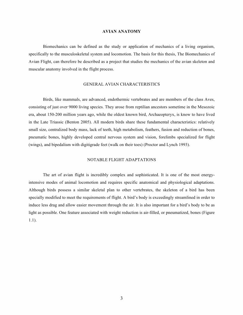
light as possible. One feature associated with weight reduction is air-filled, or pneumatized, bones (Figure
1.1).
4
Figure 1.1: Pneumatized section of the avian humerus bone.
The avian humerus, for example, is the only pneumatized bone of the wing and demonstrates how
thin-walled bones can be combined with internal struts to create a particularly strong unit (Beaufrère
2009). The largest and most efficient flying birds, such as frigatebirds and albatrosses, have air spaces
that are interconnected and pass from the humerus to the digits and across all of the joint spaces (Podulka,
et al. 2004). The frigatebird is so specialized for soaring that even though it possesses a seven-foot
wingspan, its feathers actually weigh more than its ultralight four-ounce skeleton (Henderson 2008).
The typical avian skeleton also shows significant fusion of bone, producing a rigid skeleton that is
able to withstand the forces of flight. Bone fusion is clearly visible throughout the bird’s body. The avian
hindlimb has been reorganized, with three long bones instead of the traditional two, and toes that have
become exceptionally long. In all birds, the femur is relatively short, while the tibiotarsus (drumstick) is
typically the longest bone of the hindlimb. This bone is formed by the fusion of the distal tibia and the
proximal tarsals. The distal tarsals and metatarsals are fused to form a single structure known as the
tarsometatarsus (Podulka, et al. 2004). This is a characteristic shared with modern reptiles, and may be an
artifact of evolution of birds from reptiles. Also, all modern birds lack the outermost, or fifth, toe.
5
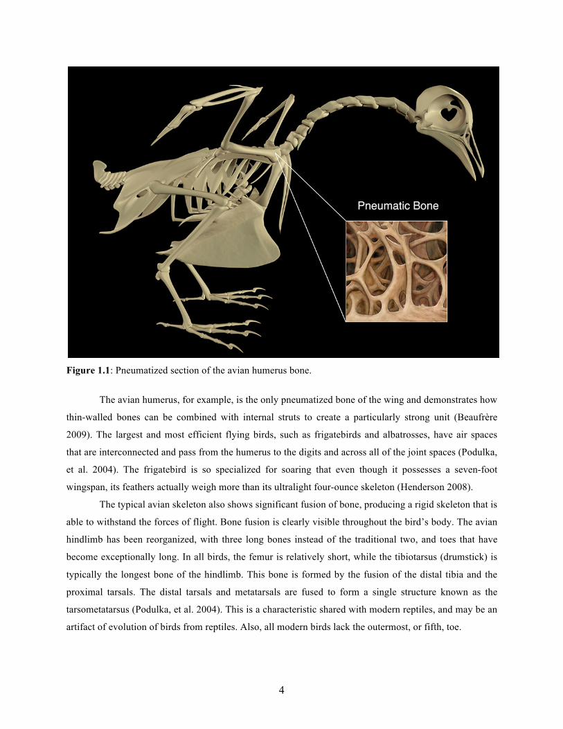
A bird’s tail is comprised of 4-9 caudal vertebrae that are fused to form the pygostyle, which
provides an attachment point for feathers of the tail (Figure 1.2).
Figure 1.2: The avian caudal vertebrae fused to form the pygostyle.
Despite the simple appearance of a bird’s tail, its internal components provide a bird with a great
deal of maneuverability and contribute significantly to the flight process (Kaiser 2007). The lumbar
vertebrae, the first 6 caudal vertebrae, the ilium, the ischium, and the pubis are fused into the pelvic
girdle. The ridge on the posterior surface of the pelvic girdle is referred to as the synsacrum. Central
sections of the vertebral column are fused into rigid blocks to cope with the mechanical stresses of flight,
as well as simple acts of running and jumping. Because of this, birds (unlike most vertebrates) are
notoriously stiff-backed, and have necks that are long and incredibly flexible to compensate (Kaiser
2007).
A bird’s skull has also been highly modified to reduce weight and to aid in the ability to fly. Early
in the evolutionary process, birds lost their heavy teeth and instead are equipped with a heavy bill
(Cameron, et al. 1979). The eyes and brain have become exceptionally large and contribute the greatest
amount of weight to a bird’s head. The avian skull also possesses only one point of contact with the neck;
a single occipital condyle articulates with the first cervical vertebra of the neck, the atlas (Kaiser 2007).
This is a characteristic that is shared with dinosaurs and their various reptilian descendants. Mammals
6
possess two occipital condyles instead of one, and it is believed that this characteristic allows for up and
down movement of the head without compressing or pinching the spinal cord. Even without this feature,
birds have evolved incredibly flexible necks with a head that has an enormous range of motion. Members
of the order Strigiformes (the owls), for example, can rotate their heads through an almost complete circle
(Cameron, et al 1979).
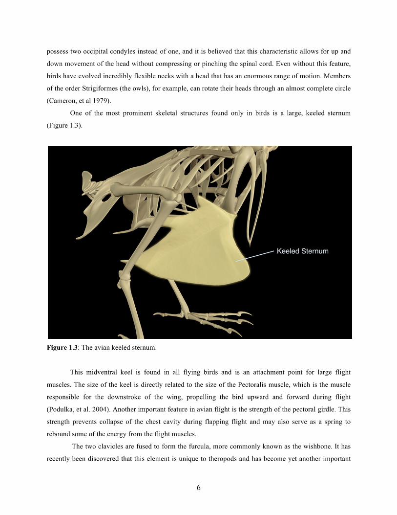
One of the most prominent skeletal structures found only in birds is a large, keeled sternum
(Figure 1.3).
Figure 1.3: The avian keeled sternum.
This midventral keel is found in all flying birds and is an attachment point for large flight
muscles. The size of the keel is directly related to the size of the Pectoralis muscle, which is the muscle
responsible for the downstroke of the wing, propelling the bird upward and forward during flight
(Podulka, et al. 2004). Another important feature in avian flight is the strength of the pectoral girdle. This
strength prevents collapse of the chest cavity during flapping flight and may also serve as a spring to
rebound some of the energy from the flight muscles.
The two clavicles are fused to form the furcula, more commonly known as the wishbone. It has
recently been discovered that this element is unique to theropods and has become yet another important
7
link between birds and theropod dinosaurs (Podulka, et al. 2004). The specific flight requirements of a
bird directly influence the morphology of the furcula, which functions to preserve the symmetry of wing
beats and the shoulders, holding the wings away from the sternum during contraction of the wing (Kaiser
2007). The furcula also acts as a spring to restore part of the mechanical forces, and participates in
protraction of the wing by action of its muscles (Beaufrère 2009). There are also seven ribs on either side
of the vertebral column, each possessing an uncinate process at the posterior margin of the ventral
surface. These processes form lateral braces between adjacent ribs and serve to strengthen the chest cavity
(Proctor and Lynch 1993).
THE AVIAN PECTORAL LIMB: SPECIALIZATION OF THE WING
Evolution has specially modified the avian forelimb as a wing. Like the other special
characteristics of the avian skeleton, it reflects the bird’s commitment to flight. Perhaps the most
interesting aspect of avian wings is that, unlike the wings of an airplane, they continuously change shape
to allow a bird to speed up, slow down, and even hover in mid-air (Henderson 2008).
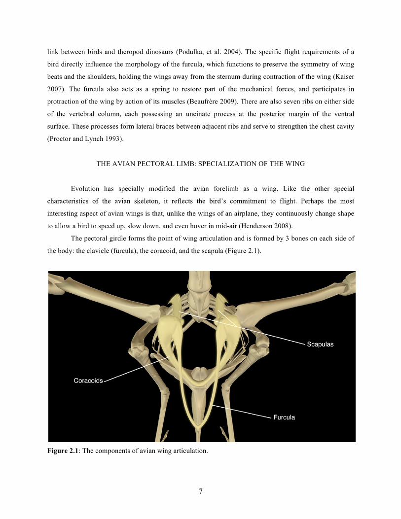
The pectoral girdle forms the point of wing articulation and is formed by 3 bones on each side of
the body: the clavicle (furcula), the coracoid, and the scapula (Figure 2.1).
Figure 2.1: The components of avian wing articulation.
8
The three-way joint between these 3 bones forms an opening known as the triosseal canal,
through which the tendon of the Supracoracoideus muscle passes. This triosseal canal serves as part of a
pulley system that allows the downward force of the contracting muscles to be redirected to an upward
pull on the dorsal surface of the wing (Proctor and Lynch 1993).
The bird’s complex shoulder joint, or glenoid articulation, is formed by the coracoid, scapula, and
humerus (Beaufrère 2009). These bones function as a powerful brace that hold the shoulder joint, and thus
the wing, away from the body while the breast muscles pull oppositely on the wing during flight
(Podulka, et al. 2004). The humerus is one of the strongest bones of the wing, and is short and stout
relative to the total length of the wing. This is because the main flight muscles of the wing attach only to
the humerus and it must resist large forces during flapping flight. The radius and ulna then form the
support for the mid-wing. These two bones articulate with each other as well as with the humerus and the
carpal bones (Beaufrère 2009) and are entirely analogous to the same structures in mammals.
Most of the distal wing bones have been extensively fused and reduced in order to strengthen the
wing. The wrist bones, carpals, and metacarpals have been fused into a single structure known as the
carpometacarpus. The avian hand, or manus, has only three digits, the first of which, known as the pollex,
or thumb, supports feathers of the alula (which is essential for slow flight, landing, gliding flight, and the
prevention of stalling) (Proctor and Lynch 1993).
BREAST MUSCLES
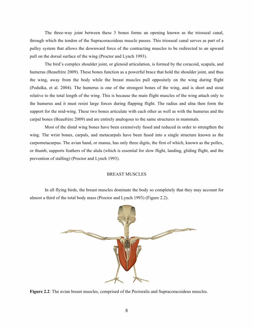
In all flying birds, the breast muscles dominate the body so completely that they may account for
almost a third of the total body mass (Proctor and Lynch 1993) (Figure 2.2).
Figure 2.2: The avian breast muscles, comprised of the Pectoralis and Supracoracoideus muscles.
9
These are the muscles that provide the power needed to achieve flight, and the Pectoralis muscle
alone makes up about 15-25% of a bird’s body weight. This large, complex muscle originates on the keel
of the sternum and inserts on the ventral surface of the humerus, producing the downstroke of the wing.
The downstroke involves extension, pronation, and abduction of the manus; extension and rotation of the
forearm; and extension and rotation of the arm (Beaufrère 2009). The Pectoralis muscle is the largest
muscle in flying birds because it takes the most force to produce lift and thrust. The Supracoracoideus is a
fusiform-shaped muscle that also originates on the keel of the sternum, laying deep to the Pectoralis. It
passes through the triosseal canal to insert on the dorsal surface of the humerus, rotating (elevating) the
wing to produce the upstroke. The upstroke involves flexion, supination, and adduction of the manus;
flexion and rotation of the forearm; and flexion and rotation of the arm (Beaufrère 2009). This
Supracoracoideus muscle is most critical in the take-off phase of flight, and is somewhat less important in
recovering the wing from the downstroke once the bird is airborne (Proctor and Lynch 1993).
MUSCLES OF THE SHOULDER
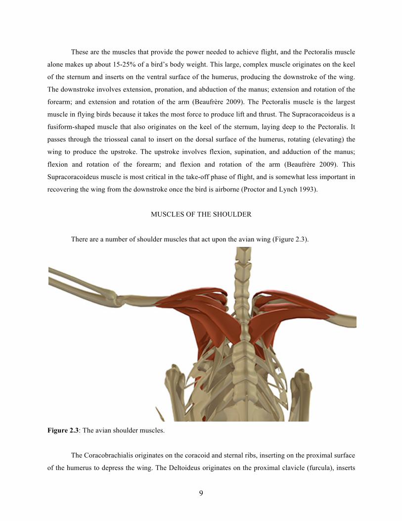
There are a number of shoulder muscles that act upon the avian wing (Figure 2.3).
Figure 2.3: The avian shoulder muscles.
The Coracobrachialis originates on the coracoid and sternal ribs, inserting on the proximal surface
of the humerus to depress the wing. The Deltoideus originates on the proximal clavicle (furcula), inserts
10
on the deltoid tuberosity of the proximal surface of the humerus, and functions to flex the shoulder and
rotate the wing. The Teres major originates on the lateral caudal surfaces of the scapula, and inserts on the
proximal ventral surface of the humerus, elevating and adducting the wing. The Latissimus dorsi is the
most superficial muscle layer on the back (Kovacs and Meyers 2000), originating on the supraspinous
ligament of the thoracic spine to insert on the proximal surface of the humerus, adducting and flexing the
wing, moving it backward and dorsally.
MUSCLES OF THE PECTORAL LIMB: BRACHIUM
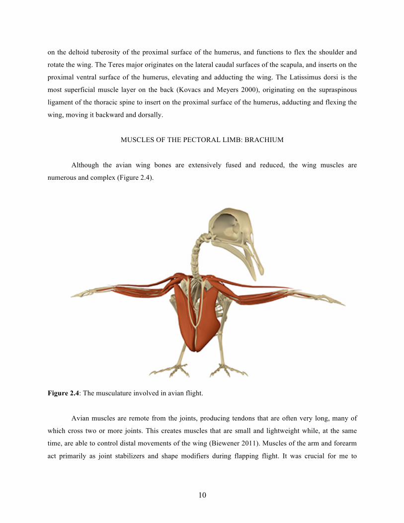
Although the avian wing bones are extensively fused and reduced, the wing muscles are
numerous and complex (Figure 2.4).
Figure 2.4: The musculature involved in avian flight.
Avian muscles are remote from the joints, producing tendons that are often very long, many of
which cross two or more joints. This creates muscles that are small and lightweight while, at the same
time, are able to control distal movements of the wing (Biewener 2011). Muscles of the arm and forearm
act primarily as joint stabilizers and shape modifiers during flapping flight. It was crucial for me to
11
understand the origin, insertion, and function of each of these muscles in order to accurately model and
animate them for this project.
The Patagialis longus originates on the distal coracoid and Pectoralis muscle, inserting on the
dorsal surface of the carpal bones. This muscle flexes the elbow, extends the manus, and tenses the
patagium of the wing. The Biceps brachii originates near the glenoid fossa and proximal head of the
humerus, inserting on the anterior surface of the radius, serving to flex the elbow, extend the manus, and
tense the patagium of the wing. The Triceps brachii has long and short heads originating on the neck of
the scapula and proximal humerus, to insert on the olecranon process of the proximal ulna. This muscle
flexes the shoulder and extends the elbow. (Proctor and Lynch 1993)
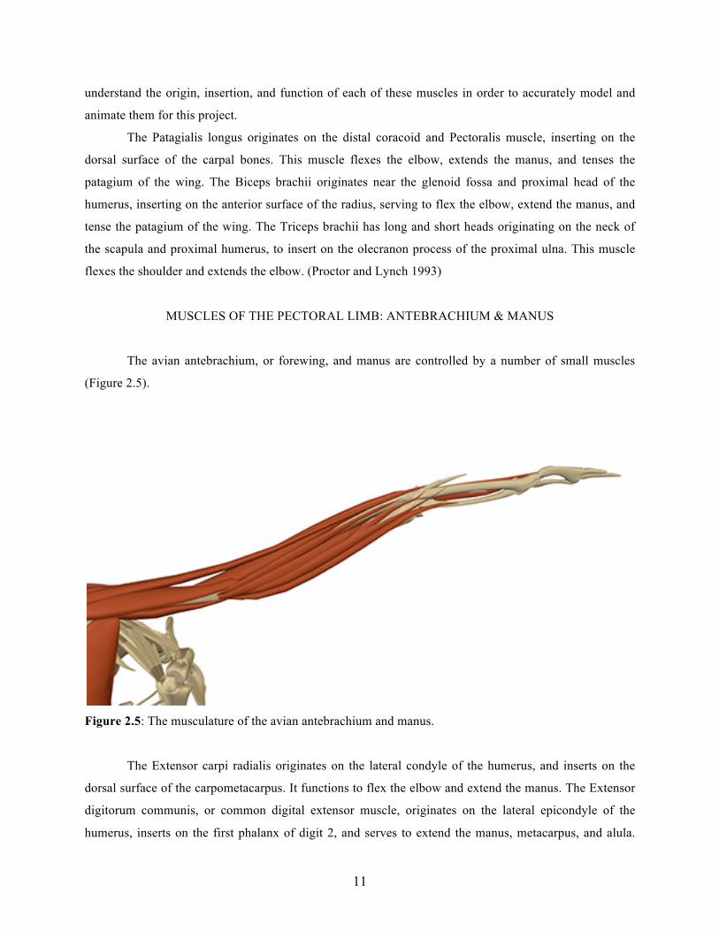
MUSCLES OF THE PECTORAL LIMB: ANTEBRACHIUM & MANUS
The avian antebrachium, or forewing, and manus are controlled by a number of small muscles
(Figure 2.5).
Figure 2.5: The musculature of the avian antebrachium and manus.
The Extensor carpi radialis originates on the lateral condyle of the humerus, and inserts on the
dorsal surface of the carpometacarpus. It functions to flex the elbow and extend the manus. The Extensor
digitorum communis, or common digital extensor muscle, originates on the lateral epicondyle of the
humerus, inserts on the first phalanx of digit 2, and serves to extend the manus, metacarpus, and alula.
12
The Ulnaris lateralis originates on the lateral epicondyle of the humerus, and inserts on the
carpometacarpus, flexing the metacarpus and helping to coordinate flexion of the manus. The Pronator’s
longus and brevis both originate on the medial epicondyle of the distal humerus and insert on the medial
surface of the radius. These muscles pronate the manus and the outer wing. The Extensor carpi obliquus
originates on the ventral surface of the medial ulna, inserts on the dorsal surface of the 2nd metacarpal, and
functions to extend and rotate the wing inward. The Flexor carpi radialis originates on the medial
epicondyle of the distal humerus, inserts on the carpometacarpus, and serves to supinate the manus, flex
the elbow, and helps erect the secondary feathers. The Flexor carpi ulnaris originates on the medial
epicondyle of the distal humerus, inserting on the ventral surface of the carpometacarpus, serving to flex
the manus and the outer wing. The Interosseous ventralis is a small muscle of the manus that originates on
the ventral surface of the carpometacarpus, inserts on the 1st and 2nd phalanges of digits two to flex digit
two. (Proctor and Lynch 1993)
THE AVIAN RESPIRATORY SYSTEM
The avian respiratory system is the most efficient in the animal kingdom and in both its large and
small details it is surprisingly unlike that of most other land vertebrates (Proctor and Lynch 1993). When
first learning about the complexities of avian flight, I failed to recognize the vital importance of the
respiratory system, and have since learned that flight would essentially be impossible if it wasn’t for the
unique respiratory anatomy that birds posses. It was important for me to include this aspect of avian
specialization to ensure that my thesis would represent a complete overview of the anatomy necessary for
flight.
The primary function of the respiratory system is to supply oxygen to the body tissue and carry
away carbon dioxide produced by high levels of metabolic activity. In birds, this process of gas exchange
is crucial because the demand for oxygen during flight is enormous. The flight muscles must receive a
large and constant supply of oxygen to maintain flight, and metabolic wastes must be removed quickly
(Proctor and Lynch 1993). Unlike mammals, birds lack a muscular diaphragm to power respiration, and
instead rely upon expansion of the ribcage to draw in air. When a bird inhales, air actually leaves the
lungs. Fresh, oxygenated air enters the lungs as the bird exhales (Proctor and Lynch 1993).
The avian respiratory system is composed of the trachea, relatively small lungs, bronchi,
pneumatic bones, and usually 9 large air sacs (Podulka, et al. 2004) (Figure 3.1).
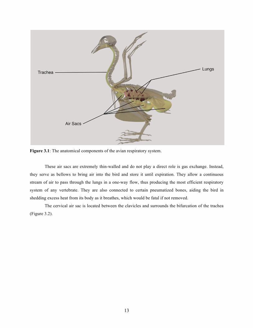
13
Figure 3.1: The anatomical components of the avian respiratory system.
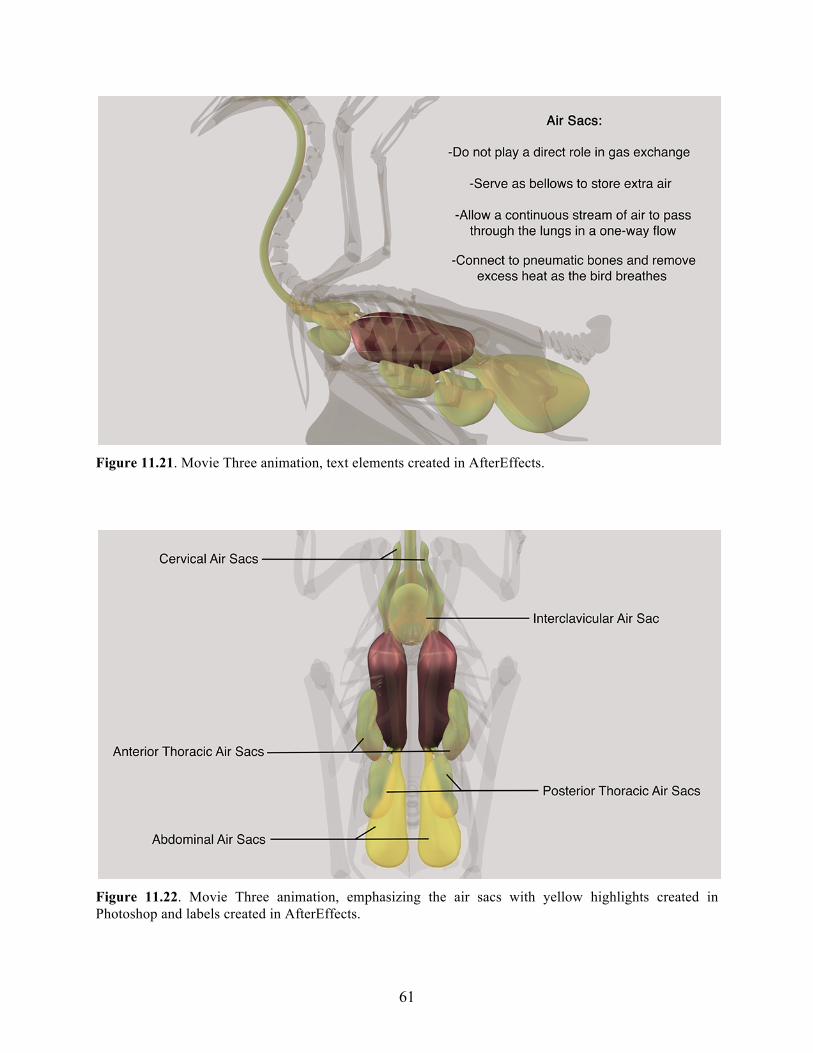
These air sacs are extremely thin-walled and do not play a direct role is gas exchange. Instead,
they serve as bellows to bring air into the bird and store it until expiration. They allow a continuous
stream of air to pass through the lungs in a one-way flow, thus producing the most efficient respiratory
system of any vertebrate. They are also connected to certain pneumatized bones, aiding the bird in
shedding excess heat from its body as it breathes, which would be fatal if not removed.
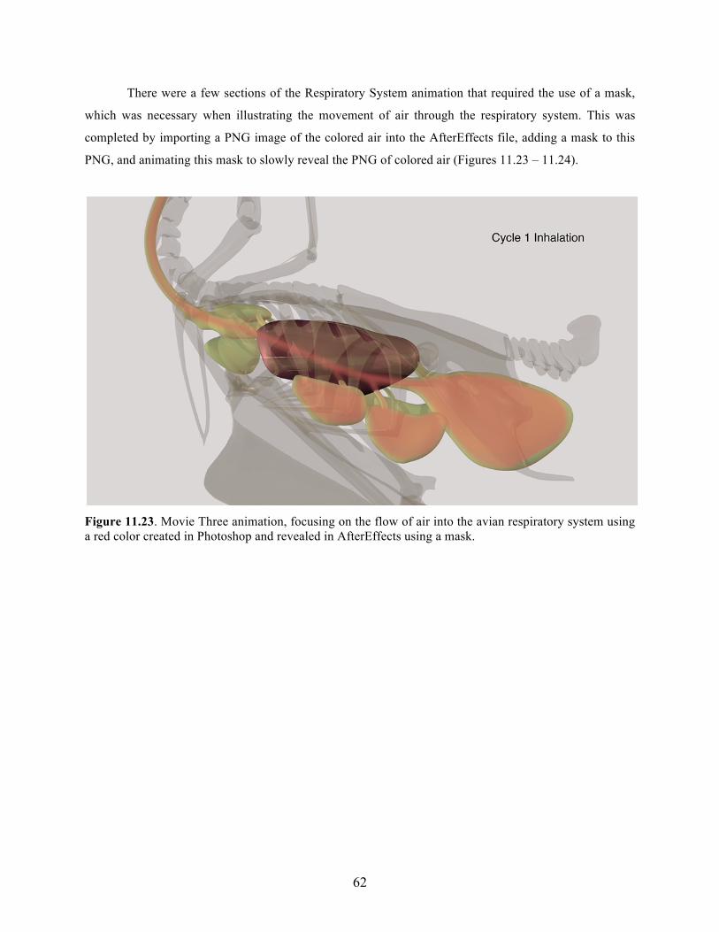
The cervical air sac is located between the clavicles and surrounds the bifurcation of the trachea
(Figure 3.2).
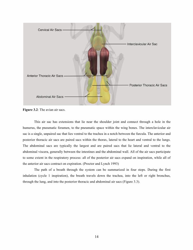
14
Figure 3.2: The avian air sacs.
This air sac has extensions that lie near the shoulder joint and connect through a hole in the
humerus, the pneumatic foramen, to the pneumatic space within the wing bones. The interclavicular air
sac is a single, unpaired sac that lies ventral to the trachea in a notch between the furcula. The anterior and
posterior thoracic air sacs are paired sacs within the thorax, lateral to the heart and ventral to the lungs.
The abdominal sacs are typically the largest and are paired sacs that lie lateral and ventral to the
abdominal viscera, generally between the intestines and the abdominal wall. All of the air sacs participate
to some extent in the respiratory process: all of the posterior air sacs expand on inspiration, while all of
the anterior air sacs contract on expiration. (Proctor and Lynch 1993)
The path of a breath through the system can be summarized in four steps. During the first
inhalation (cycle 1 inspiration), the breath travels down the trachea, into the left or right bronchus,
through the lung, and into the posterior thoracic and abdominal air sacs (Figure 3.3).

15
Figure 3.3: The path of a breath through the avian respiratory system during the first inhalation.
As the bird exhales (cycle 1 expiration) the abdomen contracts, and the air is forced out of the
posterior air sacs and into the lungs. Within the lungs, the air passes through a progressively smaller filter
of tiny air passages, called parabronchi. The smallest air passages within the lung are called the air
capillaries, and it is along the walls of these blind-ended air capillaries that the exchange of carbon
dioxide for oxygen occurs (Figure 3.4).
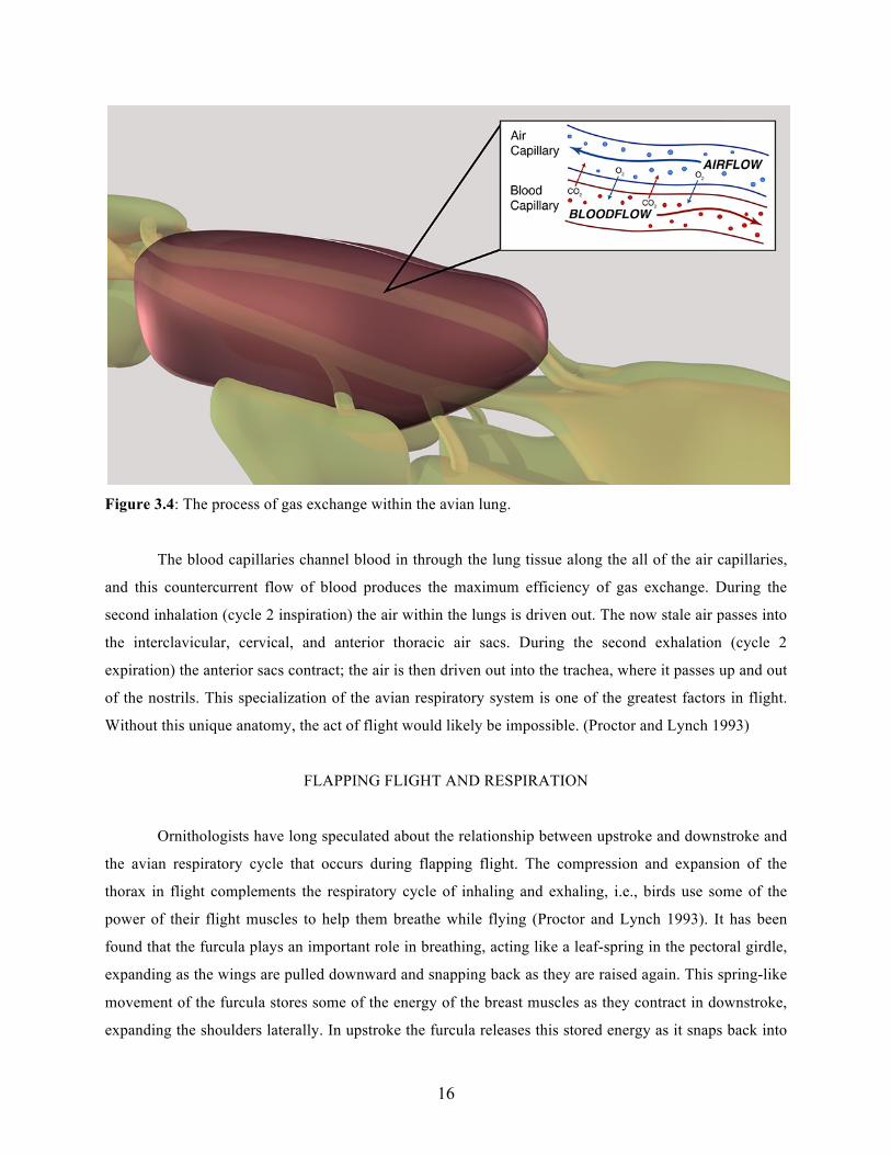
16
Figure 3.4: The process of gas exchange within the avian lung.
The blood capillaries channel blood in through the lung tissue along the all of the air capillaries,
and this countercurrent flow of blood produces the maximum efficiency of gas exchange. During the
second inhalation (cycle 2 inspiration) the air within the lungs is driven out. The now stale air passes into
the interclavicular, cervical, and anterior thoracic air sacs. During the second exhalation (cycle 2
expiration) the anterior sacs contract; the air is then driven out into the trachea, where it passes up and out
of the nostrils. This specialization of the avian respiratory system is one of the greatest factors in flight.
Without this unique anatomy, the act of flight would likely be impossible. (Proctor and Lynch 1993)
FLAPPING FLIGHT AND RESPIRATION
Ornithologists have long speculated about the relationship between upstroke and downstroke and
the avian respiratory cycle that occurs during flapping flight. The compression and expansion of the
thorax in flight complements the respiratory cycle of inhaling and exhaling, i.e., birds use some of the
power of their flight muscles to help them breathe while flying (Proctor and Lynch 1993). It has been
found that the furcula plays an important role in breathing, acting like a leaf-spring in the pectoral girdle,
expanding as the wings are pulled downward and snapping back as they are raised again. This spring-like
movement of the furcula stores some of the energy of the breast muscles as they contract in downstroke,
expanding the shoulders laterally. In upstroke the furcula releases this stored energy as it snaps back into
17
normal position, drawing the shoulders in toward the body midline. This furcular “spring” may facilitate
the movement of air between the lungs and air sacs independent of breathing. This is especially important
when remembering that birds lack a muscular diaphragm to power their respiration (Podulka, et al. 2004).
18
PRODUCTION DECISIONS
DIGITAL VS. TRADITIONAL
When embarking on this project, one of the most fundamental choices I had to make was what
medium would be used to produce the artwork. The first step in making this choice was comparing and
contrasting digital and traditional media.
Since I knew very early in my thesis that I wanted to produce animations as a final product, the
choice between digital and traditional media was relatively easy to make. Though both rendering
techniques have their pros and cons, there are many reasons why digital medium was a more logical route
to take for this project. I based my decision to work digitally on the following advantages. 1) Artwork can
be created at a much faster rate; 2) once work is created it can be used over and over again; 3) work can
be created at nearly any size and, in most cases, can be easily increased or decreased in size; 4) the
product can be easily formatted for viewing on the web; and most importantly, 5) it is much easier to
animate artwork that is created digitally.
Choosing to work digitally ultimately saved me a lot of time and energy, and also produced
higher-quality, more realistic images. It would have been nearly impossible to create my final animations
using traditional methods, considering I would have had to render literally thousands of separate
illustrations per movie. Clearly this would not have been a wise choice when working under a strict
timeline. The viewer won’t know how much time was spent creating particular images, so it is best to
choose a rendering method that will produce the highest quality images in the most reasonable amount of
time.
Another advantage of using digital medium is that there are multiple methods of back-up storage,
and files can be saved in many different locations. Works created with traditional media, however, are
relatively difficult to preserve and keep safe, very likely losing quality (fading, smudging, etc.) with time.
These traditional works are extremely vulnerable since they only exist in a single form, with no real form
of back up. Since this project was so valuable to me, it was very important that it be kept safe and saved
in multiple locations. Working digitally prevented any work from being lost and ensured that multiple
forms of the file existed, providing insurance against that inevitable software crash.
19
3D VS. 2D ANIMATING
One of the greatest difficulties in grasping the biomechanical aspects of avian flight is visualizing
the movement and interaction of the various anatomical components. Although a series of static images
might aid in this understanding to some extent, an animated sequence of images is usually much more
effective. This was the main reason I chose to create animations as opposed to static illustrations. I also
chose to produce animations because it was a form of delivery that I had not yet seen used with this
subject matter. Most of the artwork I had seen of avian anatomy consisted of static illustrations that
sometimes lacked a sense of cohesion. It is much easier to comprehend avian anatomy if you can see how
it moves and how all of the separate elements relate to each other, working together to produce various
forms of motion.
After making the decision to work digitally and through animation, I next had to choose between
2D or 3D rendering techniques. I ultimately chose to render my images out in a 3D rather than a 2D
environment based on a number of different considerations. To start, images that are created using 3D
software are much easier to animate, producing a cleaner, more realistic product. It was important to me
that the final product of this project to be as realistic-looking as possible, anticipating that the model of
the bird anatomy would closely resemble the anatomy of a living bird. I wanted the avian skeleton,
muscles, and respiratory anatomy to appear very life-like and move in a very natural way, allowing the
viewer to observe the images and then picture the anatomy within any real bird. It was clear to me that
creating 3D models for this project would be the best way to create these images and animations that I
envisioned. This was going to be the most logical method of rendering and animating my ideas for this
project, allowing them to be more easily “brought to life”.
The use of 3D software has many other advantages that were influential in my decision. The
ability to re-use any models in different animations, or even for different projects at a later date is an
appealing advantage, saving both time and hard work. Another rather obvious advantage of 3D software,
as opposed to a 2D method, is the production of a more striking, or “slick”, product. It helps in making
subject matter that may initially be seen as boring, more interesting and engaging. Though 3D modeling
and animating produces a good-looking product, it is by no means easy, and requires a lot of education
and practice to perfect. Because of these requirements, the production and use of 3D images may
highlight a certain skill set that might not be very common. Producing a high quality product using 3D
software demonstrates that one has spent a significant amount of time learning the software and put a
great deal of effort into the final product.
20
Throughout this project it was important for me to remain consistent with the different
animations, applying the same rendering and animating techniques to each. This was relatively easy since
the “main characters” in each movie were all able to be rendered in 3D, ensuring that each animation had
a similar feel and look to it. Before starting the rendering process of this project, I believed that I would
illustrate the musculature in a 2D environment as opposed to a 3D one. I planned on this only because I
wasn’t initially confident in my ability to model and rig the muscles in 3D, since I had never done
anything like that before. However, I did a lot of research on creating and rigging 3D muscle and decided
that I should at least try it out. After testing this technique, I found that it was actually not that difficult,
and that rendering the muscles in 3D would produce a much better product than if I had tried to render
them in 2D. This would have created an inconsistent product; with a 3D skeleton model and 2D
musculature, the muscles would have looked very out of place. The ability to model and animate the
muscles in the same environment as the rest of the work allowed the animation to flow much better. The
muscles turned out to look very natural when applied to the skeleton, in both appearance and movement.
It was very important for me to incorporate the anatomy of the respiratory system as a 3D
component in this project. This was because I had never viewed the respiratory anatomy in such a way,
and to my knowledge, it had not yet been created in a 3D environment to be used as an educational
resource. Any previous images I had seen (both illustrations and animations) of the avian respiratory
system were only in 2D and were difficult to understand. I wanted to create this unique anatomy in a way
that would easily relate to the skeletal anatomy of the bird and would straightforwardly demonstrate its
specialization. I also wanted to be able to show the respiratory system from a number of different angles,
providing the viewer with a comprehensive overview of the anatomy and how it functions as a whole. The
only logical way to achieve this sort of product was to create the anatomy in a 3D environment.
I wanted the final product of this thesis to be an educational movie in order to make the scientific
material more interesting and engaging to the viewer. Animations, in general, seem to be more interesting
learning tools then static illustrations or images. Another advantage of animation is that the viewers are
able to control what they are viewing. The ability to move forward, pause, and go backward in the
timeline provides the viewer with a sense of control and a way to learn the material at their own pace,
possibly providing a better learning experience overall.
I also wanted to provide narration to the movie, instead of static text images, producing a final
movie that engages the viewer with the 3D animations, narration, and labels (text). This stimulates the
viewer in more ways than a static image would, and may promote a more effective and enjoyable learning
experience. It was important for me to create an animation that was not only visually striking, but highly
educational and informative as well. I wanted the images to enhance the information and make the viewer
interested in learning more about the topic. The project would have failed if the final animation looked

21
nice, but failed to educate the viewer. As a Medical Illustrator, it is my job to find the perfect balance
between educational content and image quality. Sometimes the quality of an image must be sacrificed in
order to portray the proper information within the image, and vice versa. This project represents an
informative tool that has a very good balance of image quality and educational content.
It is also useful that 3D images can be rendered at just about any size. For my animations, I chose
to render by images at a very large scale, 1920x1800 pixels at a resolution of 300 pixels-per-inch. This
produced a high quality, high-resolution animation as the final product. An animation at such a large size
maintains the same quality when viewed on monitors of various sizes: from the large 27 inch computer
screen to the small 4 inch screen of a smart phone. It was important that the final product of this thesis be
easily viewed in the various technological platforms that are common these days. Smaller animations,
such as ones intended for web viewing, were easily rendered at a much smaller size. The ability to choose
the exact size of the final image, but still be able to go back and increase or decrease the size of that
image is a useful feature of 3D software.
22
PRODUCTION PROCESS
THESIS WEBSITE
Prior to the creating any artwork for this project, I developed a website that would be dedicated to
the process of the production of this thesis. I intended for this website to document the progress of the
project, from the first preliminary sketches through the final animation.
Designing a website that recorded the entire production process provides a more comprehensive
method of delivery and shows how my thought progress evolved, as well as how the artwork improved
over time. It helps to document the entire process instead of focusing on the final result. To develop this
website, I created an address on Rochester Institute of Technology’s server using my student account,
naming it http://cias.rit.edu/~kmk1417/thesis/home.html. To create the actual website, I used a
combination of scripting in HTML, CSS, and JavaScript. These techniques were used to develop a
comprehensive website that contained a number of different pages; each dedicated to a different aspect of
the thesis and its production.
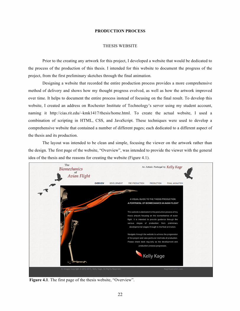
The layout was intended to be clean and simple, focusing the viewer on the artwork rather than
the design. The first page of the website, “Overview”, was intended to provide the viewer with the general
idea of the thesis and the reasons for creating the website (Figure 4.1).
Figure 4.1. The first page of the thesis website, “Overview”.
23
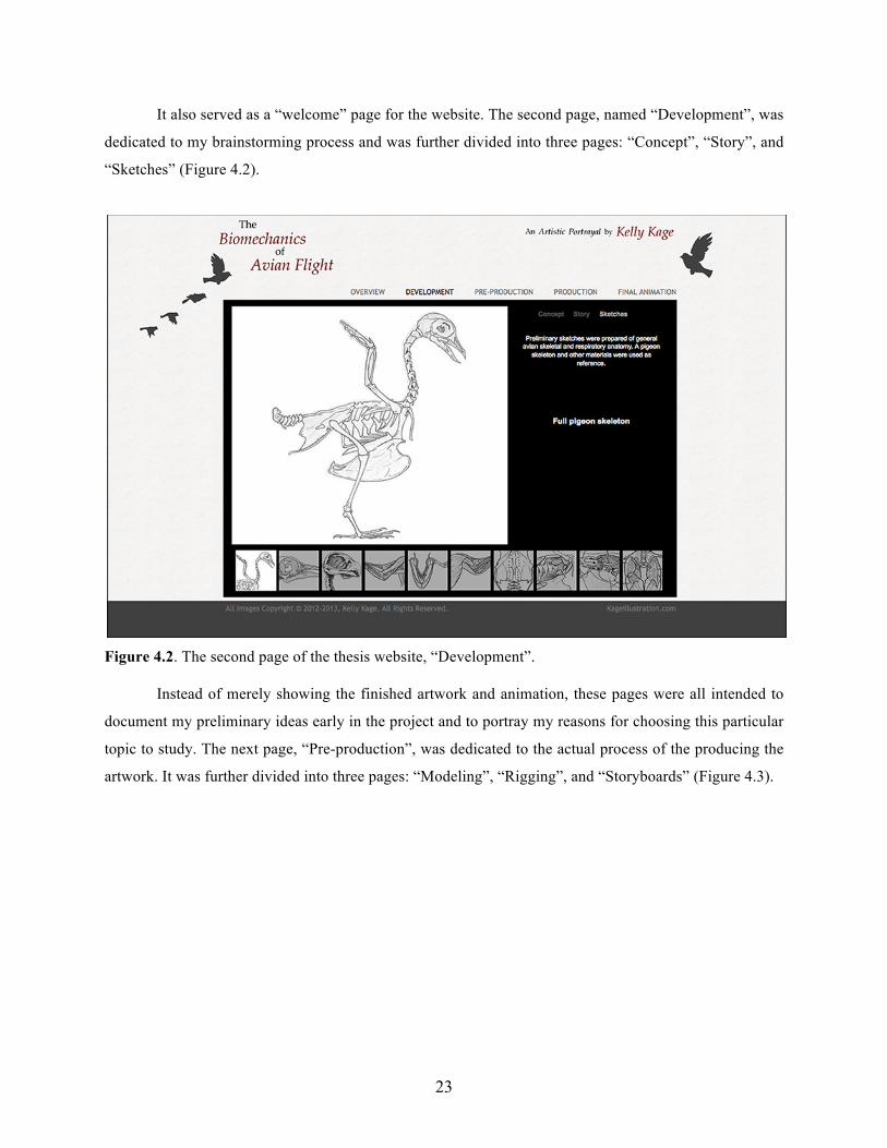
It also served as a “welcome” page for the website. The second page, named “Development”, was
dedicated to my brainstorming process and was further divided into three pages: “Concept”, “Story”, and
“Sketches” (Figure 4.2).
Figure 4.2. The second page of the thesis website, “Development”.
Instead of merely showing the finished artwork and animation, these pages were all intended to
document my preliminary ideas early in the project and to portray my reasons for choosing this particular
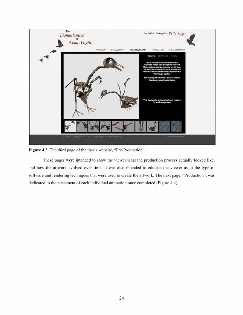
topic to study. The next page, “Pre-production”, was dedicated to the actual process of the producing the
artwork. It was further divided into three pages: “Modeling”, “Rigging”, and “Storyboards” (Figure 4.3).
24
Figure 4.3. The third page of the thesis website, “Pre-Production”.
These pages were intended to show the viewer what the production process actually looked like,
and how the artwork evolved over time. It was also intended to educate the viewer as to the type of
software and rendering techniques that were used to create the artwork. The next page, “Production”, was
dedicated to the placement of each individual animation once completed (Figure 4.4).
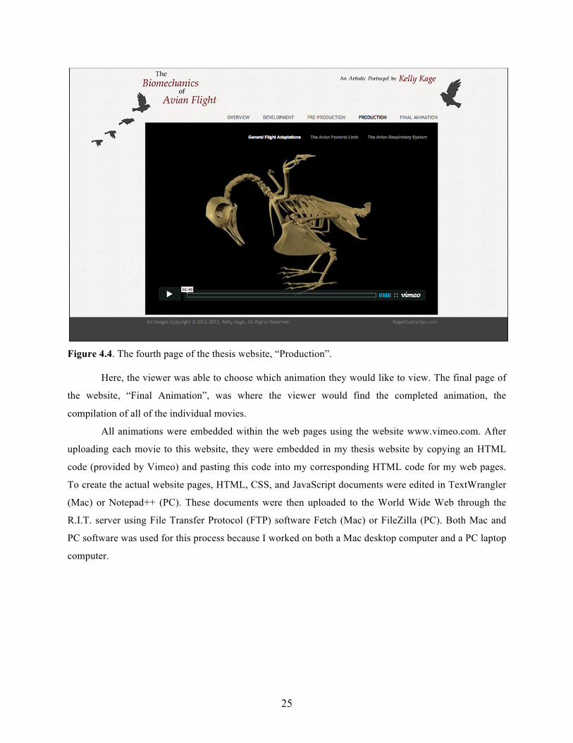
25
Figure 4.4. The fourth page of the thesis website, “Production”.
Here, the viewer was able to choose which animation they would like to view. The final page of
the website, “Final Animation”, was where the viewer would find the completed animation, the
compilation of all of the individual movies.
All animations were embedded within the web pages using the website www.vimeo.com. After
uploading each movie to this website, they were embedded in my thesis website by copying an HTML
code (provided by Vimeo) and pasting this code into my corresponding HTML code for my web pages.
To create the actual website pages, HTML, CSS, and JavaScript documents were edited in TextWrangler
(Mac) or Notepad++ (PC). These documents were then uploaded to the World Wide Web through the
R.I.T. server using File Transfer Protocol (FTP) software Fetch (Mac) or FileZilla (PC). Both Mac and
PC software was used for this process because I worked on both a Mac desktop computer and a PC laptop
computer.
26
NARRATION & STORYBOARDING
After researching the necessary scientific material for each movie in depth, general notes were
made for each movie. These notes included a broad range of information that might be included in each
movie. From here, the information was narrowed down to what was crucial information for each
animation. This included the minimal amount of material that would still provide a great deal of education
to the viewer. It was necessary to condense the material to a realistic amount to allow each movie to be a
reasonable length and to ensure that I would have enough time to complete each animation. The
condensed information was then used to create a rough narration script for each of the three movies. The
narration was recorded by myself and was created and edited using Audacity, exporting each file in AIFF
format. Each narration script was edited and perfected several times before the final narration was
recorded.
Storyboards were created for each of the three movies using Adobe Illustrator. Each of these
storyboards included images, camera directions, timing, and the anticipated narration for each individual
movie (Figure 5.1).
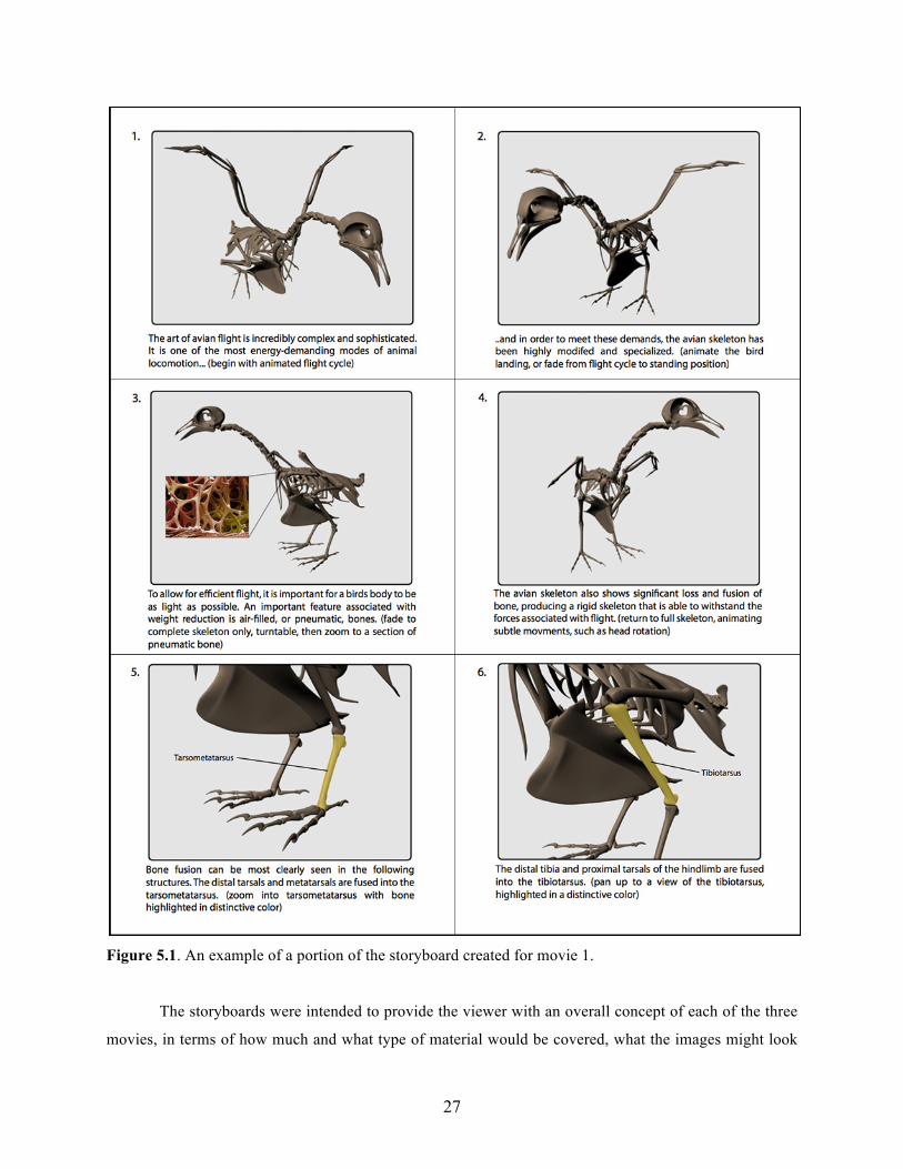
27
Figure 5.1. An example of a portion of the storyboard created for movie 1.
The storyboards were intended to provide the viewer with an overall concept of each of the three
movies, in terms of how much and what type of material would be covered, what the images might look
28
like, and the approximate length of each movie. The use of storyboards simulated how the anticipated
project would be presented to an actual client, instead of just a viewer. If the client was unhappy with the
storyboards in any way, they could very easily be adjusted before major work for the project began. This
would ensure that the client had a good idea what they were getting before the project is completed, and
helps prevent any confusion or disagreements down the line.
3D MODELING: SKELETON
The majority of the artwork created for this project was rendered in 3D using Autodesk Maya
2013. The first step of the modeling process was to create an accurate 3D model of an avian skeleton. For
reference, I purchased a mounted and articulated skeleton of a pigeon (rock dove). This skeleton was
sketched and photographed at various angles to provide reference images in Maya. A pigeon was the best
available reference because it is a common bird that has been well studied, and includes the general
skeletal adaptations that are found in all flying birds. Chicken skeletons are also readily available but
since chickens do not fly very often, they have different skeletal anatomy than birds that spend a
significant amount of time in flight.
To begin the modeling process, reference images (such as sketches) were imported into Maya as
image planes. Each individual skeletal element first began as a simple polygon cube. Various techniques
were used to model each element to accurately represent the skeletal elements of the pigeon. Since the
bird’s skeleton is symmetrical, all of the elements could be first modeled on the left side of the body.
Once the elements were accurately (though roughly) modeled, they could each be duplicated and mirrored
to the right side of the body. This method ensured that the final model was symmetrical and accurate, and
also saved a significant amount of time. Repeated skeletal elements, such as the ribs and cervical
vertebrae, were easily duplicated to create the proper number of each element. Each duplicated element
was then individually modified for anatomical accuracy. This way, the element maintained a similar
overall shape, and saved time from having to create each rib and vertebra from scratch.
Once the entire skeleton was modeled, all of the skeletal elements were brought together to
accurately “build” the bird. All of the models were first kept relatively rough with a small number of
faces, and were only smoothed when the entire model was complete. Each individual element was also
assigned a simple UV map to ensure that any shaders applied would appear uniform over the entire
model. During the modeling process, only a default shader was used on the entire surface of the model.
Only after the entire model was complete and smoothed was a bone textured shader applied to entire
surface. This layered bone shader was adjusted in various ways in terms of color and bump map to give
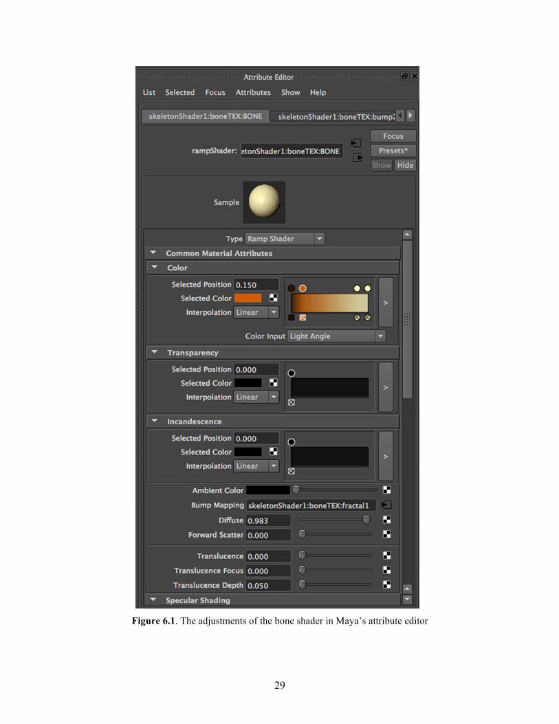
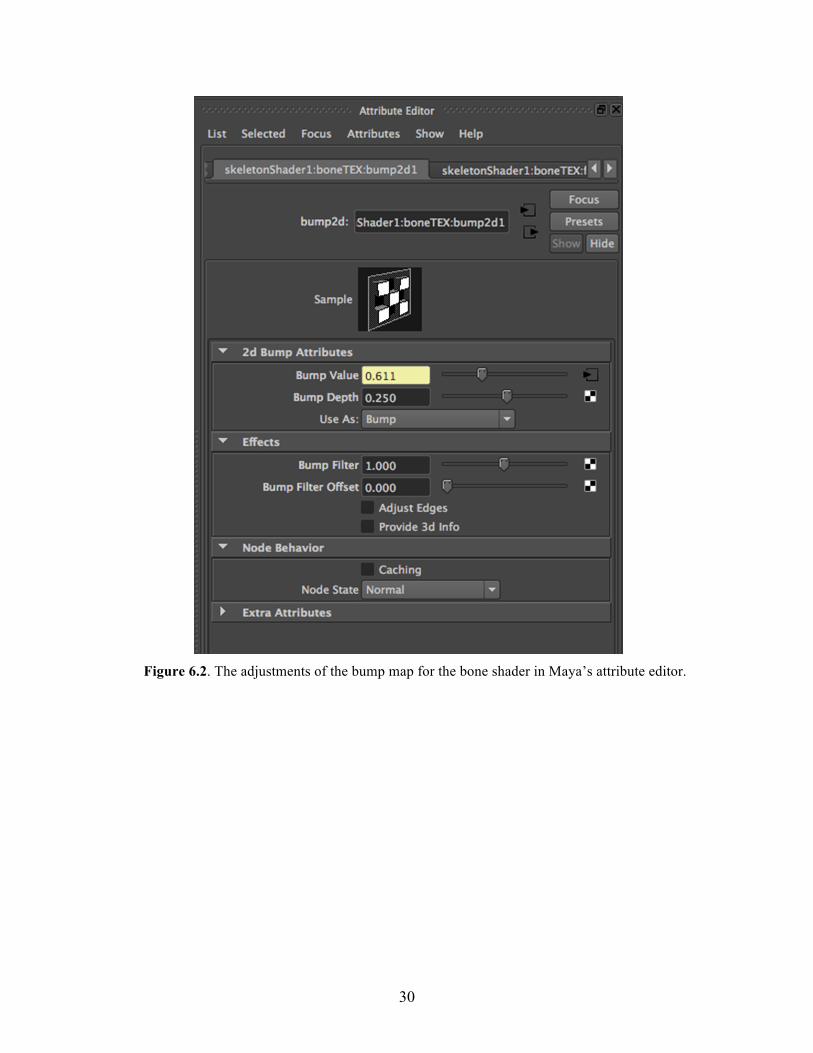
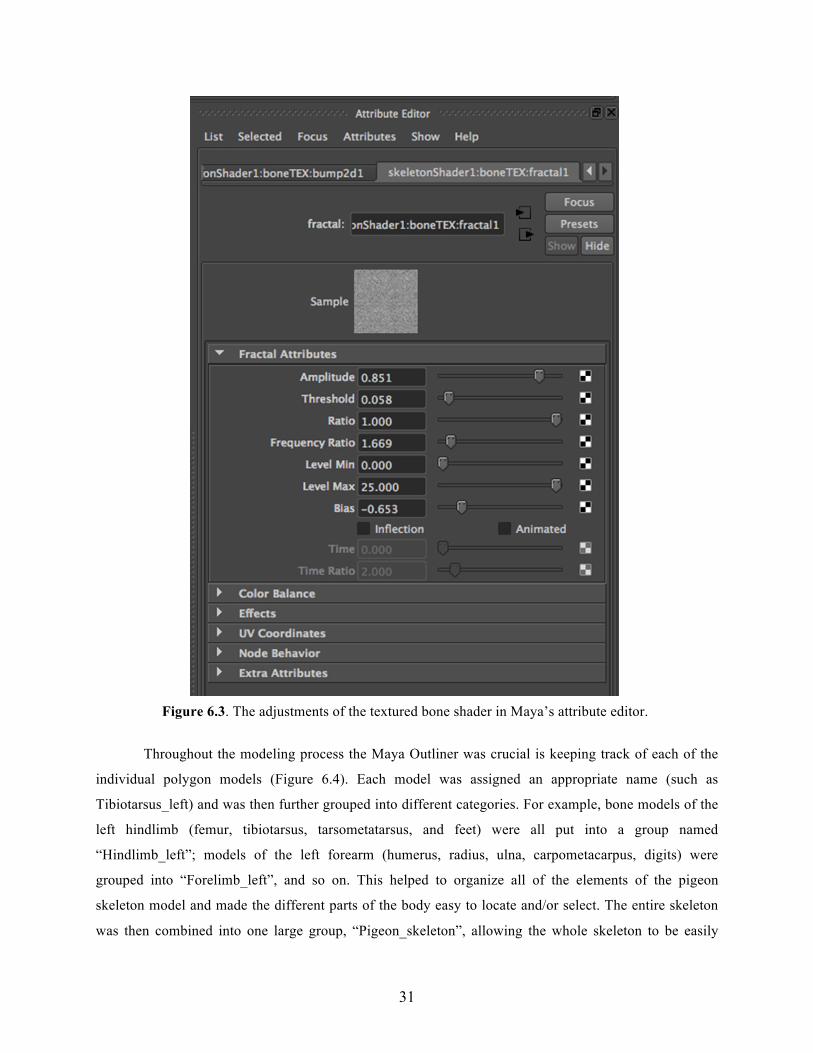
the skeleton the appearance of actual bone (Figures 6.1 - 6.3).
29
Figure 6.1. The adjustments of the bone shader in Maya’s attribute editor
30
Figure 6.2. The adjustments of the bump map for the bone shader in Maya’s attribute editor.
31
Figure 6.3. The adjustments of the textured bone shader in Maya’s attribute editor.
Throughout the modeling process the Maya Outliner was crucial is keeping track of each of the
individual polygon models (Figure 6.4). Each model was assigned an appropriate name (such as
Tibiotarsus_left) and was then further grouped into different categories. For example, bone models of the
left hindlimb (femur, tibiotarsus, tarsometatarsus, and feet) were all put into a group named
“Hindlimb_left”; models of the left forearm (humerus, radius, ulna, carpometacarpus, digits) were
grouped into “Forelimb_left”, and so on. This helped to organize all of the elements of the pigeon
skeleton model and made the different parts of the body easy to locate and/or select. The entire skeleton
was then combined into one large group, “Pigeon_skeleton”, allowing the whole skeleton to be easily
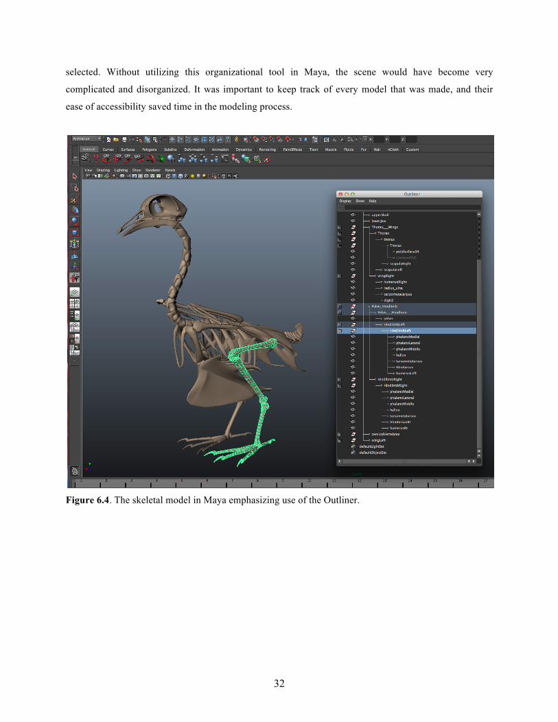
32
selected. Without utilizing this organizational tool in Maya, the scene would have become very
complicated and disorganized. It was important to keep track of every model that was made, and their
ease of accessibility saved time in the modeling process.
Figure 6.4. The skeletal model in Maya emphasizing use of the Outliner.
33
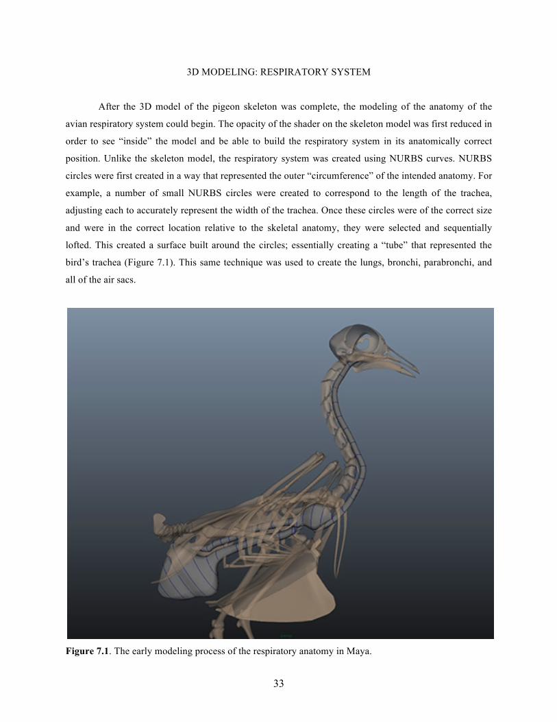
3D MODELING: RESPIRATORY SYSTEM
After the 3D model of the pigeon skeleton was complete, the modeling of the anatomy of the
avian respiratory system could begin. The opacity of the shader on the skeleton model was first reduced in
order to see “inside” the model and be able to build the respiratory system in its anatomically correct
position. Unlike the skeleton model, the respiratory system was created using NURBS curves. NURBS
circles were first created in a way that represented the outer “circumference” of the intended anatomy. For
example, a number of small NURBS circles were created to correspond to the length of the trachea,
adjusting each to accurately represent the width of the trachea. Once these circles were of the correct size
and were in the correct location relative to the skeletal anatomy, they were selected and sequentially
lofted. This created a surface built around the circles; essentially creating a “tube” that represented the
bird’s trachea (Figure 7.1). This same technique was used to create the lungs, bronchi, parabronchi, and
all of the air sacs.
Figure 7.1. The early modeling process of the respiratory anatomy in Maya.
34
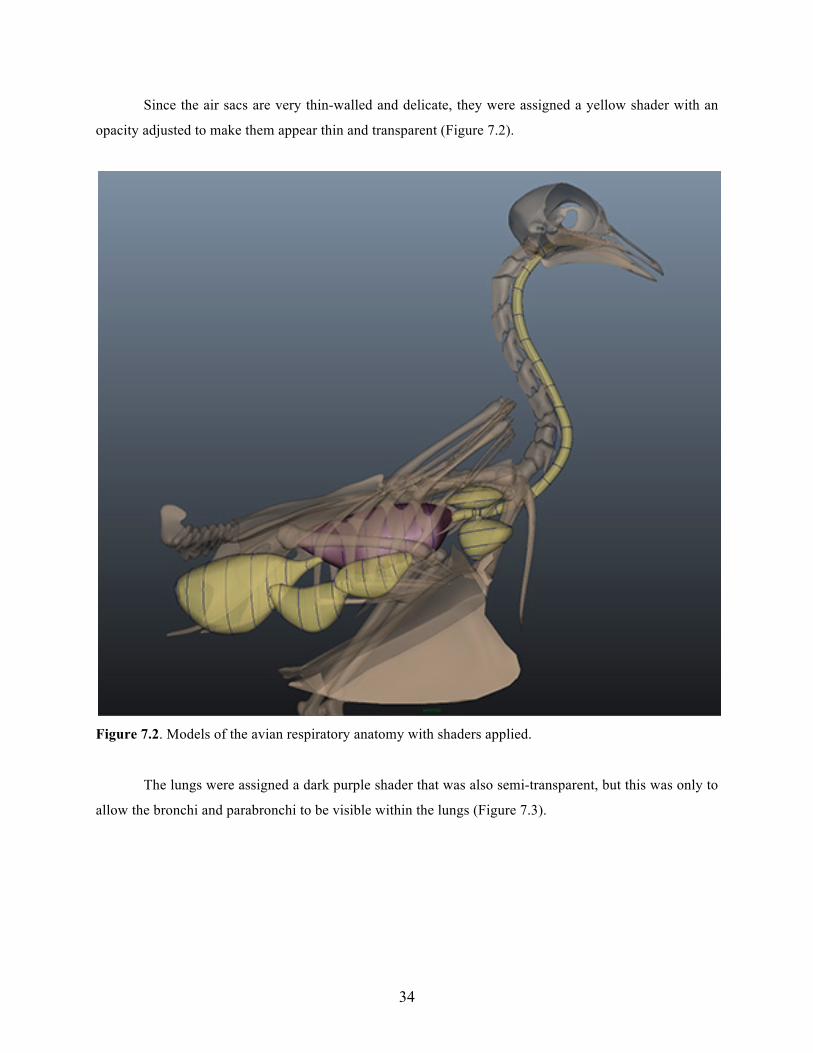
Since the air sacs are very thin-walled and delicate, they were assigned a yellow shader with an
opacity adjusted to make them appear thin and transparent (Figure 7.2).
Figure 7.2. Models of the avian respiratory anatomy with shaders applied.
The lungs were assigned a dark purple shader that was also semi-transparent, but this was only to
allow the bronchi and parabronchi to be visible within the lungs (Figure 7.3).
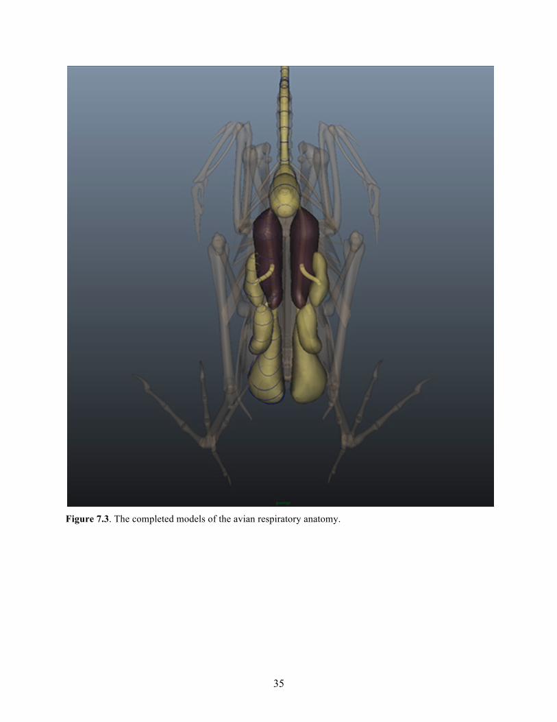
35
Figure 7.3. The completed models of the avian respiratory anatomy.
36
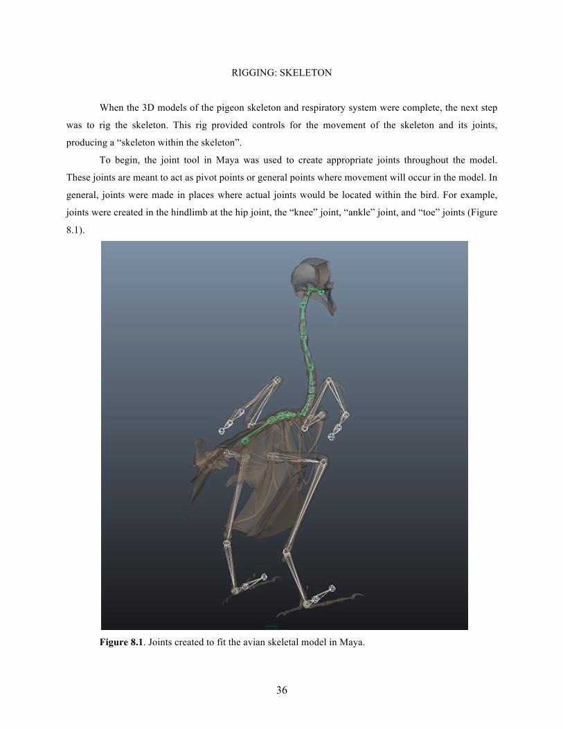
RIGGING: SKELETON
When the 3D models of the pigeon skeleton and respiratory system were complete, the next step
was to rig the skeleton. This rig provided controls for the movement of the skeleton and its joints,
producing a “skeleton within the skeleton”.
To begin, the joint tool in Maya was used to create appropriate joints throughout the model.
These joints are meant to act as pivot points or general points where movement will occur in the model. In
general, joints were made in places where actual joints would be located within the bird. For example,
joints were created in the hindlimb at the hip joint, the “knee” joint, “ankle” joint, and “toe” joints (Figure
8.1).
Figure 8.1. Joints created to fit the avian skeletal model in Maya.
37
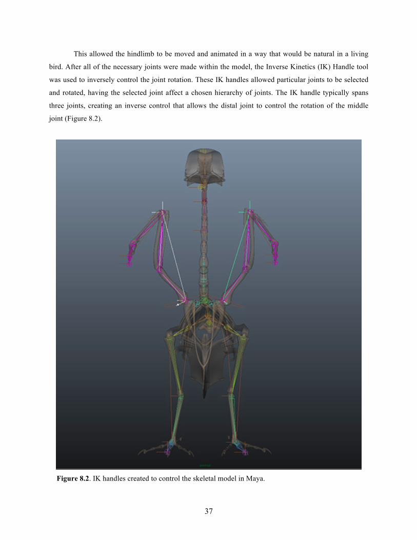
This allowed the hindlimb to be moved and animated in a way that would be natural in a living
bird. After all of the necessary joints were made within the model, the Inverse Kinetics (IK) Handle tool
was used to inversely control the joint rotation. These IK handles allowed particular joints to be selected
and rotated, having the selected joint affect a chosen hierarchy of joints. The IK handle typically spans
three joints, creating an inverse control that allows the distal joint to control the rotation of the middle
joint (Figure 8.2).
Figure 8.2. IK handles created to control the skeletal model in Maya.
38
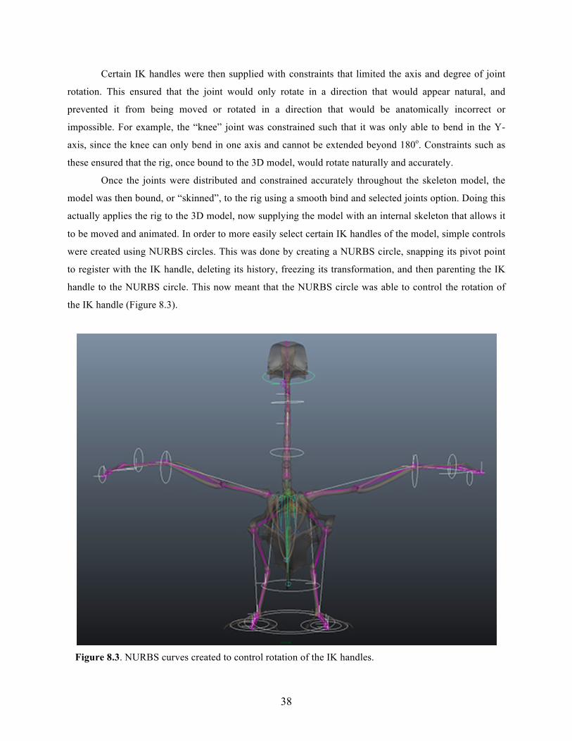
Certain IK handles were then supplied with constraints that limited the axis and degree of joint
rotation. This ensured that the joint would only rotate in a direction that would appear natural, and
prevented it from being moved or rotated in a direction that would be anatomically incorrect or
impossible. For example, the “knee” joint was constrained such that it was only able to bend in the Y-
axis, since the knee can only bend in one axis and cannot be extended beyond 180o. Constraints such as
these ensured that the rig, once bound to the 3D model, would rotate naturally and accurately.
Once the joints were distributed and constrained accurately throughout the skeleton model, the
model was then bound, or “skinned”, to the rig using a smooth bind and selected joints option. Doing this
actually applies the rig to the 3D model, now supplying the model with an internal skeleton that allows it
to be moved and animated. In order to more easily select certain IK handles of the model, simple controls
were created using NURBS circles. This was done by creating a NURBS circle, snapping its pivot point
to register with the IK handle, deleting its history, freezing its transformation, and then parenting the IK
handle to the NURBS circle. This now meant that the NURBS circle was able to control the rotation of
the IK handle (Figure 8.3).
Figure 8.3. NURBS curves created to control rotation of the IK handles.
39
This was done to various IK handles because locating and selecting these handles can become
quite difficult once the model becomes complicated. Since the NURBS circles are arbitrary and can be
made to any size that you want, they are much easier to see and select and are an overall simpler way to
control the handles. In addition, the simple geometry of the NURB circle makes it easier for the software
to calculate the rotation of the joint in response to the controls movement. It was also useful to parent
different NURBS circles to other, larger circles, therefore creating a hierarchy of controls to choose from.
Since Maya does not render NURBS curves, they were essentially invisible and did not show up as part of
the image when the scene was rendered.
RIGGING & MODELING: MUSCULATURE
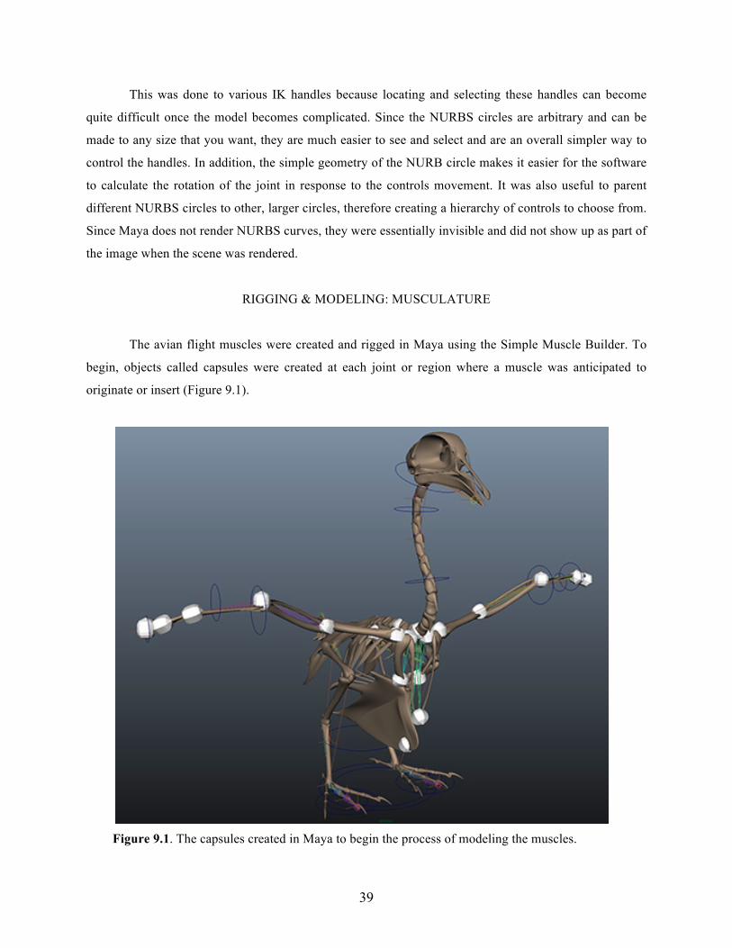
The avian flight muscles were created and rigged in Maya using the Simple Muscle Builder. To
begin, objects called capsules were created at each joint or region where a muscle was anticipated to
originate or insert (Figure 9.1).
Figure 9.1. The capsules created in Maya to begin the process of modeling the muscles.

40
These were necessary to create starting and ending points for the muscles and to have them
connect and move accordingly to the appropriate joints. These capsules were created in the sternum,
shoulder, scapula, “elbow”, “wrist”, and “hand” on each side of the model.
After the capsules were created, the individual muscles could then be modeled. In the simple
muscle builder, the capsule where the muscle originated was selected as the “input”, while the capsule
where the muscle inserted was selected as the “output”. When created, a muscle was built between these
two capsules, rigged appropriately to the connected joints (Figure 9.2).
Figure 9.2. The Simple Muscle Builder in Maya used to model the flight musculature.
The individual muscle could then be modified and shaped to portray a correct representation of
the actual muscle using CV’s that were created in the process. Once the muscle was the correct shape and
size, it was also necessary to make sure that the muscle moved properly and corresponded to the bones of
41
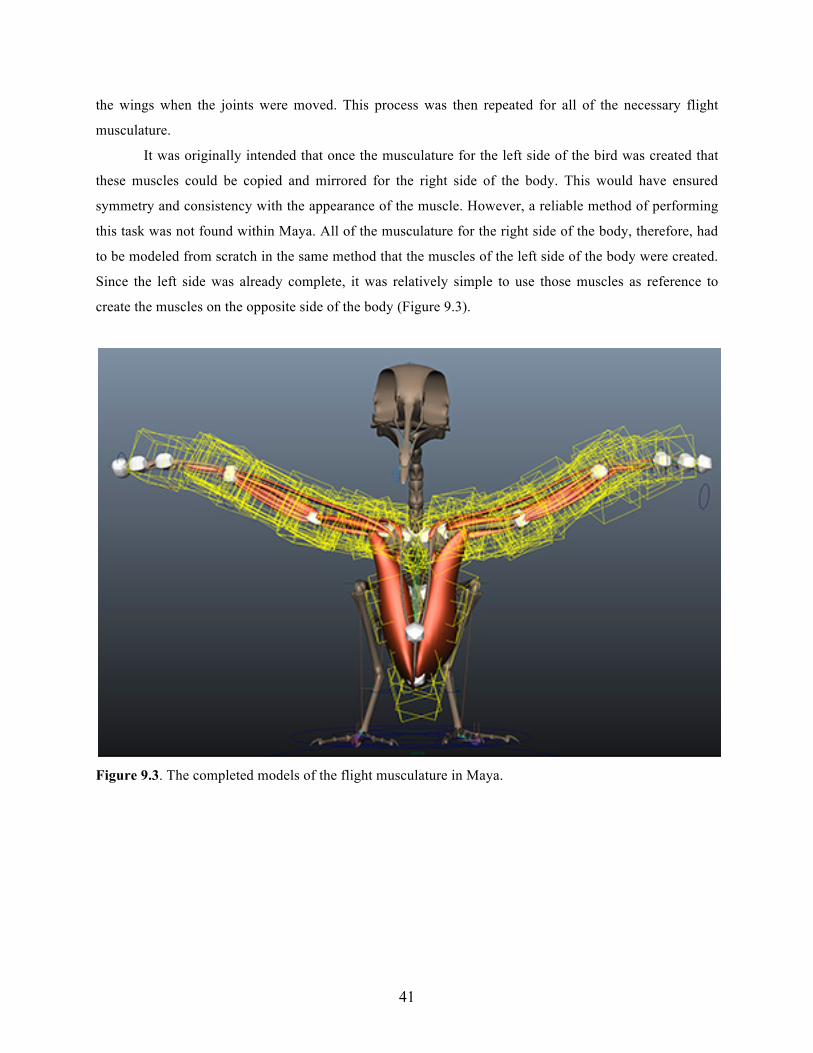
the wings when the joints were moved. This process was then repeated for all of the necessary flight
musculature.
It was originally intended that once the musculature for the left side of the bird was created that
these muscles could be copied and mirrored for the right side of the body. This would have ensured
symmetry and consistency with the appearance of the muscle. However, a reliable method of performing
this task was not found within Maya. All of the musculature for the right side of the body, therefore, had
to be modeled from scratch in the same method that the muscles of the left side of the body were created.
Since the left side was already complete, it was relatively simple to use those muscles as reference to
create the muscles on the opposite side of the body (Figure 9.3).
Figure 9.3. The completed models of the flight musculature in Maya.
42
ANIMATING: MAYA
Once all of the necessary 3D components were completed in Maya, the process of animating
could then begin. To start, the render settings in Maya were set to a size of 1920x1080 (1080 HD) at a
resolution of 300 pixels-per-inch (PPI). This ensured that a high quality animation would be produced.
The file format was set to PNG, allowing the background of each image to be rendered as transparent.
This was important because the actual background color of the animations was best determined while
completing the final animations. If at some point I decided to change the background color of the
animation, I didn’t have to go back and re-render every frame out of Maya.
For each of the three movies, a different scene in Maya was used. This prevented too much
history from building up on the models and allowed each animation to have its own settings. Prior to
animating, it was crucial that any unnecessary history on the model was deleted and all transformations
were frozen. This helped to prevent any errors while rendering the animation sequences, since any
unwanted history on the model could have added unwanted information to the already complex
animations; it is important to start with a “clean slate” when animating. For each of the three animations,
a separate camera for rendering was created; the “Render Camera” was the camera that was used when
rendering all of the image sequences. This allowed changes to be made to the model through a separate
camera (such as the perspective or front camera), and prevented any work on the animation from being
lost or altered.
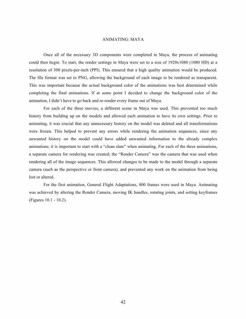
For the first animation, General Flight Adaptations, 800 frames were used in Maya. Animating
was achieved by altering the Render Camera, moving IK handles, rotating joints, and setting keyframes
(Figures 10.1 - 10.2).
43
Figure 10.1. The completed model of the avian skeleton rendered out of Maya and posed for animation.
44
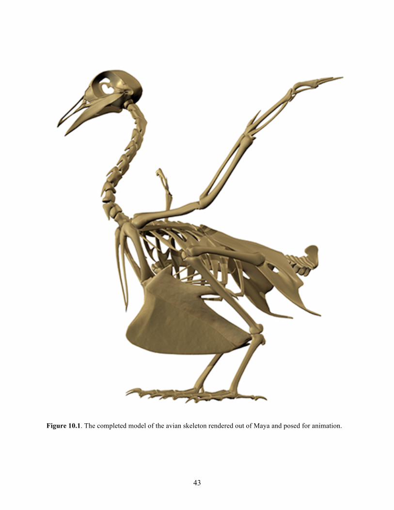
Figure 10.2. The completed model of the avian skeleton rendered out of Maya.
After the skeleton and camera were both animated as desired, the rendering was broken up into a
number of different segments. For example, I would choose to render frames 001-120 and then frames
120-200. This allowed the animation to be broken up into smaller sections that would better correspond to
the previously recorded narration. This worked out better than simply rendering the entire animation (all
800 frames) in a single shot. This technique was used for each of the three animations. This would later
allow a still image to be inserted between two animation sequences, causing a “pause” in the animation to
allow for more time for corresponding narration.
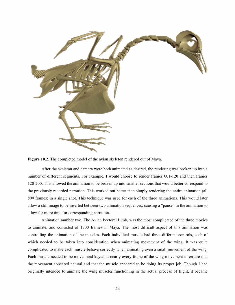
Animation number two, The Avian Pectoral Limb, was the most complicated of the three movies
to animate, and consisted of 1700 frames in Maya. The most difficult aspect of this animation was
controlling the animation of the muscles. Each individual muscle had three different controls, each of
which needed to be taken into consideration when animating movement of the wing. It was quite
complicated to make each muscle behave correctly when animating even a small movement of the wing.
Each muscle needed to be moved and keyed at nearly every frame of the wing movement to ensure that
the movement appeared natural and that the muscle appeared to be doing its proper job. Though I had
originally intended to animate the wing muscles functioning in the actual process of flight, it became
45
quite difficult to animate the entire skeleton in unison with the muscles to accurately portray the flight
process. I chose instead to animate only movements of the wing that simulated what the wing might do
and/or look like during flight. This was achieved by animating the wings in a variety of different
movements while the bird was essentially standing still (instead of actually flying). I believe this method
was successful and portrays how the muscles work together to control the wing. I find it to be a good
educational tool when trying to learn the avian flight anatomy, emphasizing the muscles that are present
in the wing, and how they relate to the skeletal anatomy of the wing (Figure 10.3).
Figure 10.3. The completed model of the avian skeleton and flight musculature rendered out of Maya.
The third animation, the Avian Respiratory System, was made up of 700 frames in Maya. The
majority this animation involved camera movements, and only included slight movements of the bird’s
head as well as inflation of the air sacs. The air sacs were animated “expanding” and “contracting” by
simply increasing or decreasing the size of the air sacs and setting keys. The most difficult aspect of the
animating was controlling the different transparencies of the skeleton and respiratory system. These
transparencies were achieved by altering the opacity of the shaders assigned to the models (Figure 10.4).

46
Figure 10.4. The completed avian skeleton and respiratory anatomy rendered out of Maya.
47
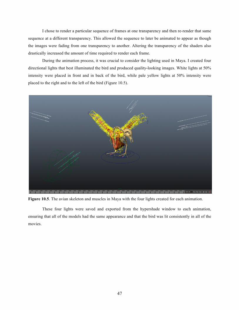
I chose to render a particular sequence of frames at one transparency and then re-render that same
sequence at a different transparency. This allowed the sequence to later be animated to appear as though
the images were fading from one transparency to another. Altering the transparency of the shaders also
drastically increased the amount of time required to render each frame.
During the animation process, it was crucial to consider the lighting used in Maya. I created four
directional lights that best illuminated the bird and produced quality-looking images. White lights at 50%
intensity were placed in front and in back of the bird, while pale yellow lights at 50% intensity were
placed to the right and to the left of the bird (Figure 10.5).
Figure 10.5. The avian skeleton and muscles in Maya with the four lights created for each animation.
These four lights were saved and exported from the hypershade window to each animation,
ensuring that all of the models had the same appearance and that the bird was lit consistently in all of the
movies.
48
ANIMATING: AfterEffects
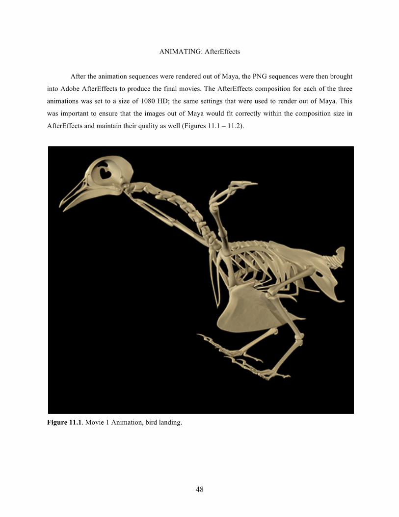
After the animation sequences were rendered out of Maya, the PNG sequences were then brought
into Adobe AfterEffects to produce the final movies. The AfterEffects composition for each of the three
animations was set to a size of 1080 HD; the same settings that were used to render out of Maya. This
was important to ensure that the images out of Maya would fit correctly within the composition size in
AfterEffects and maintain their quality as well (Figures 11.1 – 11.2).
Figure 11.1. Movie 1 Animation, bird landing.
49
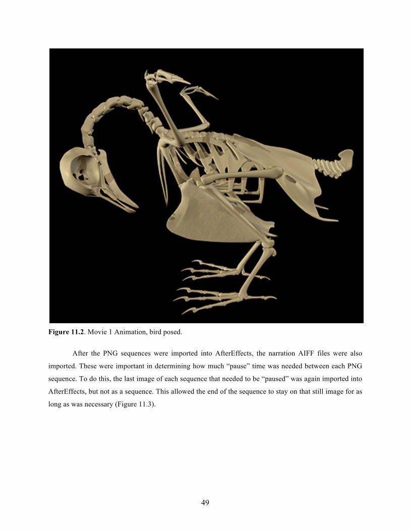
Figure 11.2. Movie 1 Animation, bird posed.
After the PNG sequences were imported into AfterEffects, the narration AIFF files were also
imported. These were important in determining how much “pause” time was needed between each PNG
sequence. To do this, the last image of each sequence that needed to be “paused” was again imported into
AfterEffects, but not as a sequence. This allowed the end of the sequence to stay on that still image for as
long as was necessary (Figure 11.3).

50
Figure 11.3. Movie One Animation, a section of pneumatic bone created in Photoshop and text elements created within AfterEffects.
Typically the length of the corresponding narration determined the amount of time this still image
was used.
Throughout the three animations there were regions where a portion of the model needed to be
“highlighted” in order to identify and label it. To do this, the frame (PNG file) in the animation where the
highlight was to occur was brought into Adobe Photoshop. A path was then created around the anatomical
element to be highlighted. This path was then selected, feathered 2-5 pixels, and then filled with a bright
yellow color. The opacity of this layer was then decreased to about 80%, still ensuring that the color
would be obvious, but that the anatomical element would be slightly visible. This image was then saved
as a PNG file, imported into the AfterEffects file, and then placed at the appropriate section of the
animation where the highlight was meant to occur (Figures 11.4 – 11.7).
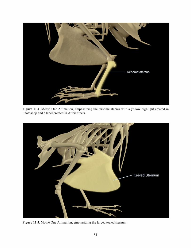
51
Figure 11.4. Movie One Animation, emphasizing the tarsometatarsus with a yellow highlight created in Photoshop and a label created in AfterEffects.
Figure 11.5. Movie One Animation, emphasizing the large, keeled sternum.
52
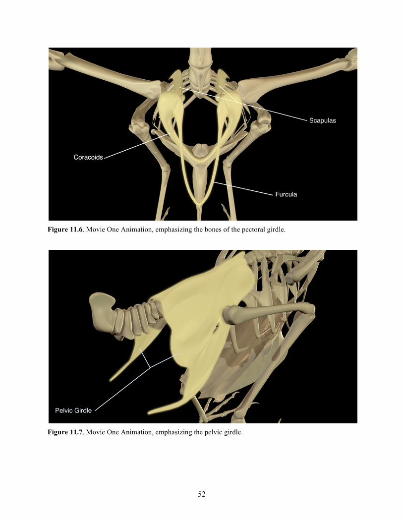
Figure 11.6. Movie One Animation, emphasizing the bones of the pectoral girdle.
Figure 11.7. Movie One Animation, emphasizing the pelvic girdle.
53
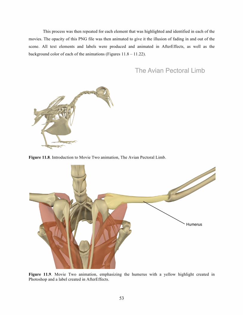
This process was then repeated for each element that was highlighted and identified in each of the
movies. The opacity of this PNG file was then animated to give it the illusion of fading in and out of the
scene. All text elements and labels were produced and animated in AfterEffects, as well as the
background color of each of the animations (Figures 11.8 – 11.22).
Figure 11.8. Introduction to Movie Two animation, The Avian Pectoral Limb.
Figure 11.9. Movie Two animation, emphasizing the humerus with a yellow highlight created in Photoshop and a label created in AfterEffects.
54
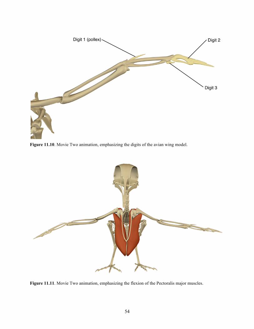
Figure 11.10. Movie Two animation, emphasizing the digits of the avian wing model.
Figure 11.11. Movie Two animation, emphasizing the flexion of the Pectoralis major muscles.
55
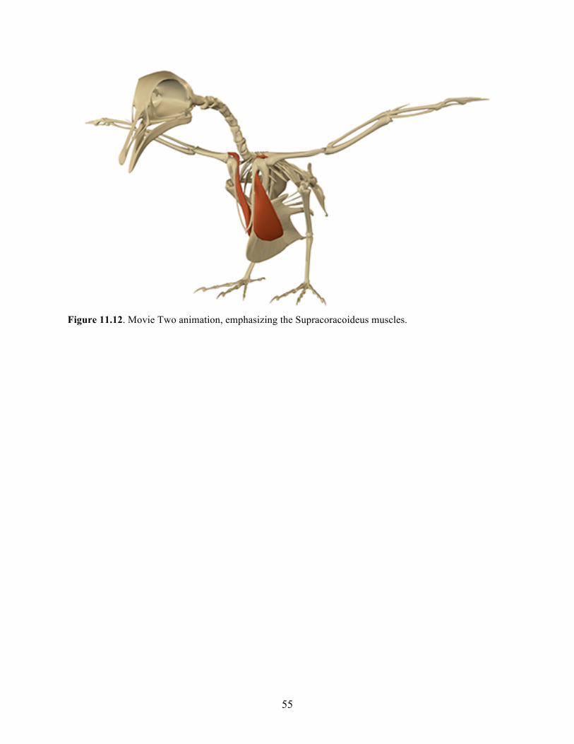
Figure 11.12. Movie Two animation, emphasizing the Supracoracoideus muscles.
56
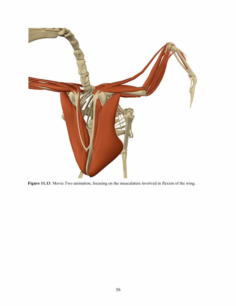
Figure 11.13. Movie Two animation, focusing on the musculature involved in flexion of the wing.
57
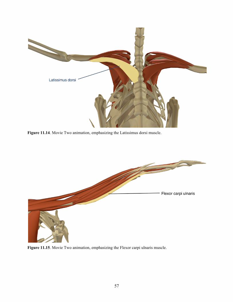
Figure 11.14. Movie Two animation, emphasizing the Latissimus dorsi muscle.
Figure 11.15. Movie Two animation, emphasizing the Flexor carpi ulnaris muscle.
58
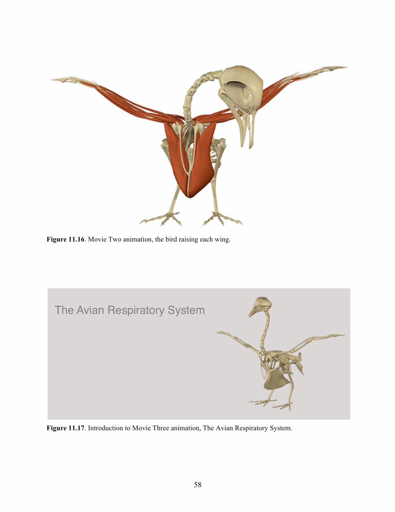
Figure 11.16. Movie Two animation, the bird raising each wing.
Figure 11.17. Introduction to Movie Three animation, The Avian Respiratory System.
59
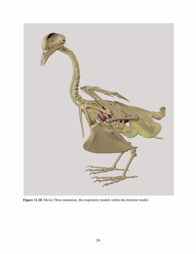
Figure 11.18. Movie Three animation, the respiratory models within the skeleton model.

60
Figure 11.19. Movie Three animation, the isolated models of the respiratory anatomy.
Figure 11.20. Movie Three animation with labels created in AfterEffects.
61
Figure 11.21. Movie Three animation, text elements created in AfterEffects.
Figure 11.22. Movie Three animation, emphasizing the air sacs with yellow highlights created in Photoshop and labels created in AfterEffects.
62
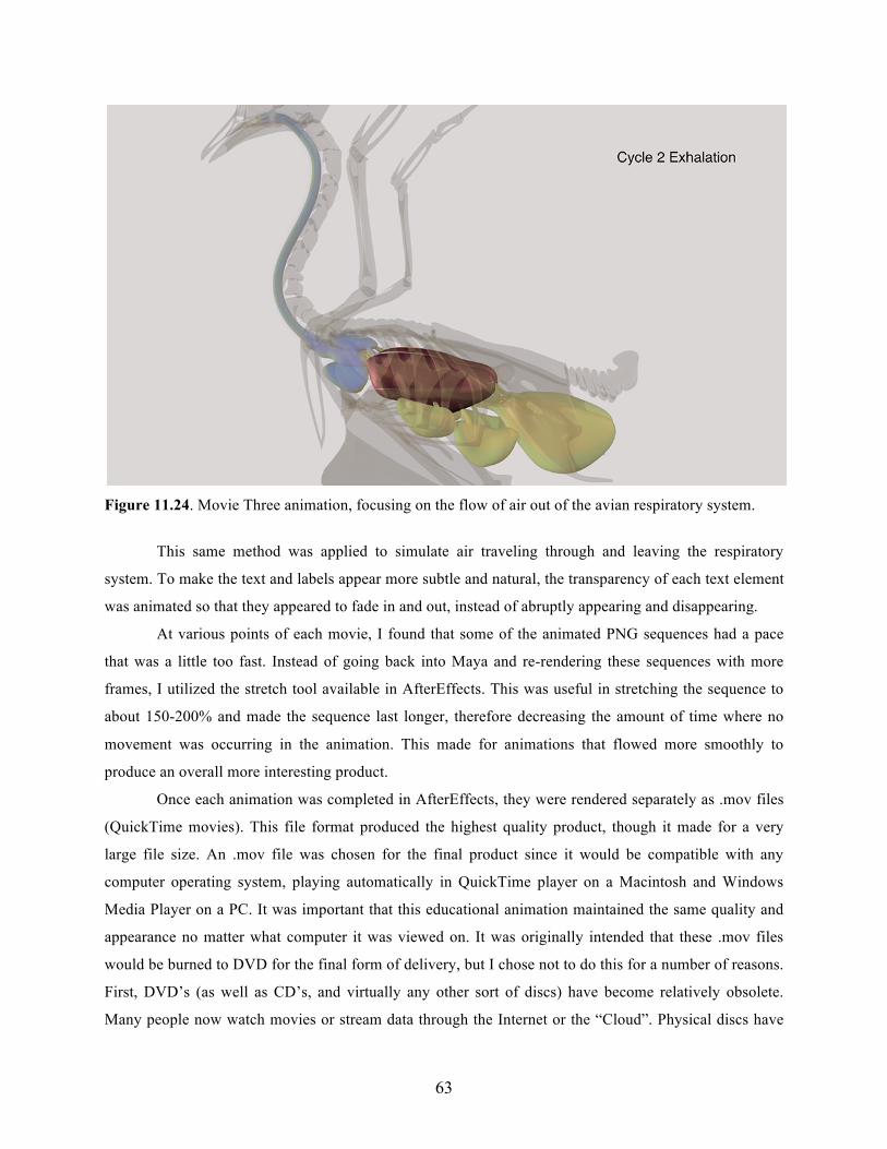
There were a few sections of the Respiratory System animation that required the use of a mask,
which was necessary when illustrating the movement of air through the respiratory system. This was
completed by importing a PNG image of the colored air into the AfterEffects file, adding a mask to this
PNG, and animating this mask to slowly reveal the PNG of colored air (Figures 11.23 – 11.24).
Figure 11.23. Movie Three animation, focusing on the flow of air into the avian respiratory system using a red color created in Photoshop and revealed in AfterEffects using a mask.
63
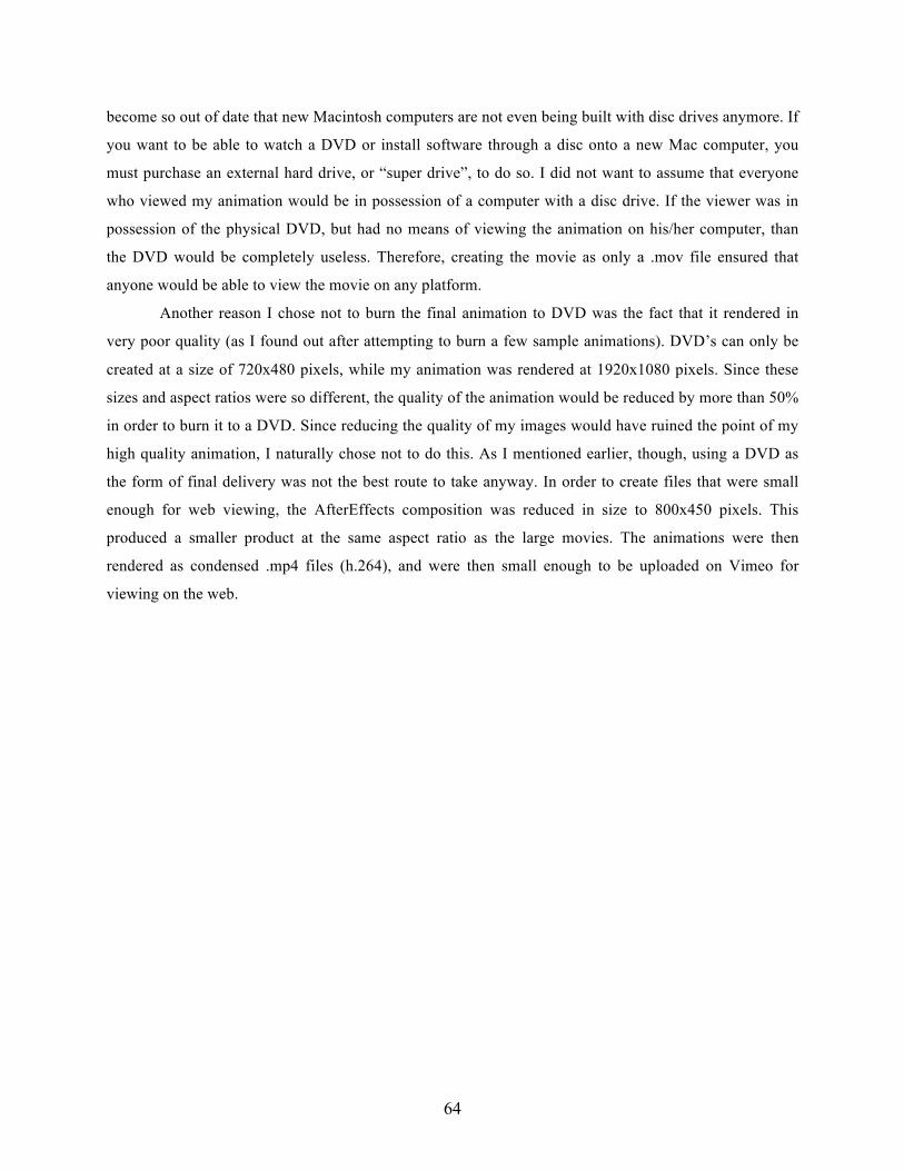
Figure 11.24. Movie Three animation, focusing on the flow of air out of the avian respiratory system.
This same method was applied to simulate air traveling through and leaving the respiratory
system. To make the text and labels appear more subtle and natural, the transparency of each text element
was animated so that they appeared to fade in and out, instead of abruptly appearing and disappearing.
At various points of each movie, I found that some of the animated PNG sequences had a pace
that was a little too fast. Instead of going back into Maya and re-rendering these sequences with more
frames, I utilized the stretch tool available in AfterEffects. This was useful in stretching the sequence to
about 150-200% and made the sequence last longer, therefore decreasing the amount of time where no
movement was occurring in the animation. This made for animations that flowed more smoothly to
produce an overall more interesting product.
Once each animation was completed in AfterEffects, they were rendered separately as .mov files
(QuickTime movies). This file format produced the highest quality product, though it made for a very
large file size. An .mov file was chosen for the final product since it would be compatible with any
computer operating system, playing automatically in QuickTime player on a Macintosh and Windows
Media Player on a PC. It was important that this educational animation maintained the same quality and
appearance no matter what computer it was viewed on. It was originally intended that these .mov files
would be burned to DVD for the final form of delivery, but I chose not to do this for a number of reasons.
First, DVD’s (as well as CD’s, and virtually any other sort of discs) have become relatively obsolete.
Many people now watch movies or stream data through the Internet or the “Cloud”. Physical discs have
64
become so out of date that new Macintosh computers are not even being built with disc drives anymore. If
you want to be able to watch a DVD or install software through a disc onto a new Mac computer, you
must purchase an external hard drive, or “super drive”, to do so. I did not want to assume that everyone
who viewed my animation would be in possession of a computer with a disc drive. If the viewer was in
possession of the physical DVD, but had no means of viewing the animation on his/her computer, than
the DVD would be completely useless. Therefore, creating the movie as only a .mov file ensured that
anyone would be able to view the movie on any platform.
Another reason I chose not to burn the final animation to DVD was the fact that it rendered in
very poor quality (as I found out after attempting to burn a few sample animations). DVD’s can only be
created at a size of 720x480 pixels, while my animation was rendered at 1920x1080 pixels. Since these
sizes and aspect ratios were so different, the quality of the animation would be reduced by more than 50%
in order to burn it to a DVD. Since reducing the quality of my images would have ruined the point of my
high quality animation, I naturally chose not to do this. As I mentioned earlier, though, using a DVD as
the form of final delivery was not the best route to take anyway. In order to create files that were small
enough for web viewing, the AfterEffects composition was reduced in size to 800x450 pixels. This
produced a smaller product at the same aspect ratio as the large movies. The animations were then
rendered as condensed .mp4 files (h.264), and were then small enough to be uploaded on Vimeo for
viewing on the web.
65
CONCLUSION
The art of avian flight is so unique and complex that it will certainly continue to be the subject of
in-depth study for many years to come. The animations that I have created have made an important
contribution to the ornithological field, and will hopefully provide others with a greater understanding of
avian flight. I believe that the three animations, whether viewed separately or as a group, present the
viewer with a broad range of educational material focusing on the biomechanical requirements for flight.
After viewing movie one, General Flight Adaptations, the learner will be able to list the skeletal
adaptations that enable birds to fly. After viewing movie two, The Avian Pectoral Limb, the learner will
be able to describe the importance and specialization of the avian wing, and explain the muscular
adaptations of the wing and how these elements function during flight. After viewing the third movie, The
Avian Respiratory System, the learner will be able to describe the importance of avian respiratory
anatomy, list the importance anatomical structures, as well as describe the steps of respiration and the
path of a breath through the system. Together, all three movies provide a relatively complete overview of
general avian anatomy and the specializations that have evolved to make birds so unique.
I hope to continue to work on this project in the future, and would like to add at least two more
animations to the completed movie. In order to provide the viewer with a more comprehensive overview
of avian flight, I believe it is important to also understand the physics of flight as well as the act of
landing. A fourth animation focusing on the physics and aerodynamics of flight would explain important
topics such as the angle of attack, the generation of lift and forward thrust, the cambered wing, and the
importance of overall wing shape. A fifth animation concentrating on the act of landing would explain
various toe arrangements seen among birds and would describe how these differences are adapted for
different life and landing styles. These two new animations, when combined with the previous three
animations, would provide the viewer with a greater educational experience regarding the complexities of
avian flight.
Throughout the production process of this thesis, I learned a great deal about new modeling and
animating techniques as well as where my own limits and strengths lie. I hope to continue my pursuit of
ornithological understanding and will continue to explore various aspects of avian flight. In the future I
plan to expand my areas of study to include avian social and sexual interactions, migration patterns, and
the ever so interesting path of avian evolution from predatory saurischian dinosaurs. This thesis has been
greatly rewarding and I hope that my efforts will help to spark an ornithological interest in the hearts and
minds of others.
66
BIBLIOGRAPHY Beaufrère, Hugues. 2009. "A Review of Biomechanic and Aerodynamic Considerations of the Avian Thoracic Limb." Journal of Avian Medicine and Surgery 23.3: 173-82. ProQuest. Web. 28 Sept. 2012. Benton, Michael J. 2005. Vertebrate Paleontology. 3rd ed. Malden, MA: Blackwell, 2005. Print. Biewener, Andrew A. 2011. "Muscle Function in Avian Flight: Achieving Power and Control." Philosophical Transactions of the Royal Society B 366 (2011): 1496-506. Philosophical Transactions of the Royal Society B: Biological Sciences. The Royal Society. Web. 26 Sept. 2012. Cameron, Ad, Christopher M. Perrins, and Colin James Oliver. Harrison. 1979. Birds: Their Life, Their Ways, Their World. Pleasantville, NY: Reader's Digest Association. Print. Henderson, Carrol L. 2008. Birds in Flight: The Art and Science of How Birds Fly. Minneapolis, MN: Voyageur. Print. Kaiser, Gary W. 2007. The Inner Bird: Anatomy and Evolution. Vancouver: UBC. Print. Kovacs, Christopher E., and Ron A. Meyers. 2000. "Anatomy and Histochemistry of Flight Muscles in a Wing-propelled Diving Bird, the Atlantic Puffin, Fratercula Arctica." Journal of Morphology 244.2: 109-25. Wiley Online Library. John Wiley & Sons, Inc. Web. 28 Sept. 2012. Podulka, Sandy, Ronald W. Rohrbaugh, and Rick Bonney. 2004. Handbook of Bird Biology. Ithaca, NY: Cornell Lab of Ornithology in Association with Princeton UP. Print. Proctor, Noble S., and Patrick J. Lynch. 1993. Manual of Ornithology: Avian Structure & Function. New Haven: Yale UP. Print.


![[dad]The Portrayal of Women1](https://img.pdfslide.us/doc/110x75/58ef29561a28ab2c4e8b4583/dadthe-portrayal-of-women1.jpg)