Embed Size (px)
Citation preview
.
UCRL-ID-125506
A Pluto-Slam .Design to Fit a Maximum Fineness Ratio Missile Into a Polaris
Launch Tube
R. S. Cornwell
DISCLAIMER
This report was prepared as an account of work sponsored by an agency of the United States Government. Neither the United States Gwernment nor any agency thercof, nor any of their emplcyees, makes any warranty, express or implied, or assume any legal liability or responsi- bility Cor the accuracy, completeness, or usefulness of any information, apparatus, product, or process disclosed, or represents that its use would not infringe privately owned rights. Refer- ence herein to any specific commercial product, process, or service by trade name, trademark, manufacturer, or otherwise does not ncccssarily constitute or imply its endorsement, rtcom-
mendation, or favoring by the United States Government or any agency thereof. The views and opinions of authors expressed herein do not necessarily state or reflect those of the United States Government or any agency thereof.
DEc ~
l%is is an informal r e m intended primarily for internal or limited external distribution. The opinions and conclusions stated am those of the author and may or may not be those of the Laboratory. Work performed under the auspices of the U.S. Department of Energy by the '1,
Lawrence Livemore National Laboratory under Contract W-7405-ENG-48. '
Portions of this document may be illegible in electronic image products. Images are produced from the best available original document.
* * 'I
Page 1 of 18 h+
I .
- October 12, 1962
. -I
.-THIS DOCJM3NT CONSISTS OF - 18 PACES
_ _ NO. - I OF - / C(3PI_Es,-%kRIES . -- . NAVAL APPLICATIONS MEavIoRANDUM #11
I , . To: Distribution
FROM : R, S. Cornwell
U J. Badley 2A A. J. Eodges/B. C o r n w e l l 3 A 11. Reynolds 4A T. Merkle
W. Myers/W. 6A W. Wells
DISTRIBUTION:
3.23 A. Lorenz 2B E. Goldberg 3B T. Stubbs 4B J. Moyer
6B A. Cole 733 B. Sheridaa
9B C. Barnett
M. Mint2
8B v. Hampel
1OB J. Thomas l lB H. Reynolds/File l 2 B E. Platt 1% C. Walter 14B J. W e 1% A, Rot- 1 6 ~ B. Rubin 17B H. McDonald 18B A. ICLrschbaum 19B P. Neal 2OB R. J. Volluz, Lockheed 21B G. H e l f r i c h 22B I. Hoffman, AM=-Washington
1C R. mey, AEE-SAN 2C J. a d c l l f f e 3C R. Cornwell kC A. Mooneybam 5c A. Carbin
u> File ZD File 3D File
f
t u . e ,
_.. _ _ _ _ - - - - - - - - - - M E M 0 R A N D U M --- October'l2, 1962
Page 2 of 18
To: J. Hadley
FROM: R. S. Cornwell
SUBJECT: _ _
A Pluto-Slam Design to F i t a Maximum Fineness Ratio Missile Into a Polaris Launch Tube e(!)
To f i t a PlUto-Slam missile into a Polaris tube requires another look at the boost system. maximum fineness ra t io to the missile and s t i l l allow f u l l use t o be made of a l l the available spaze in the tube. for a 48 inch diameter reactor used in a 9 inch diameter missile weighing ~ , O O O pounds. chamber pressure of UHX) psi and burns for 60 seconds using inhibited red fum- ing n i t r i c acid (IRFBA) as an oxidizer and JP-X (504 unsymmetrical dimethyl hydrazine, So$ JP J e t f'uel) as a fuel. (See Appendix I for calculations). should be noted that the Navy has been using at least one storable liquid propellant missile aboard ship since 1960. ile, uses IFtFNA (83.5 lbs) and MAF (Mixed Amine Fuel) (28.6 lbs) 86 propellants and is described i n Bureau of N a v a l Weapons Notice 8023 of June 1960. are stored on carriers and used on attack aircraft. Other storable liquid pro- peUant systems i n use are l i s ted in Ref. 1.
A storable liquid propellant rocket boost system catl give a
Figure 1 shows a proposed configuration
The rocket motor shown develops 130,OOO pounds of t h t at a
It
The Bullpup, an air to surface miss-
These
Many configurations of tanks and rocket motors are certainly possible but only two are considered here. influence an optimum design.
t h
Aeroaynamic and structural stabil i ty would strongly Possibly full airflow should be available through
Geometry of the first configuration considered here is to wrap the propellant tanks around the missile with a "chin" tank under the nose* The "chin*' tank is ejected as soon as possible to a l l o w limited air flow through the reactor. If full air flow through the reactor a l l the way through boost is considered necessary, this "chin" tsnk could be modified to a slipper tenk for top and side of the nose. Wings are folded in the af t tanks and are carried "wet", that is, sbuply immersed in the fluid. Sin&? fold wings likely limited to a mtiximUm area of This area could possibly be increased with the use of full highly swept delta planforms or multiple folding.
50 ftO2.
The f l igh t schedule would call for lighting off the rocket at water exit and sknultaneously bringing up reactor temperature on a schedule giving about lO00~ at the side support. the reactor to f u l l temperature. allows 8ome airflow at all times m e r the "chin1' tank is blown off,which takes place about 30 seconds a f te r launch. About 65% reactor air flow can then be maintained with the rocket motor in the nozzle. By shortening the vehicle and extending the rocket -tor further aft, more airflow is obtain- - able.
About 8 40 second wanrmp is estimated to bring hcat ion of the rocket motor in the nozzle
. > L. *.
Page 3 of 18
Figure 2 shows performance of the proposed missile based on a 3000% w a l l temperature, which appears to be quite feasible when a &me supported reactor is used. to the optinnun ramjet of Ref. 2, which is also shown on Figure 2 for compari- son. (Ref . 4,5) .
Performance calculations were "by hand" but compare satisfactorily
The drag curye is based on Ref . 3 and a comparison to other drag data Calculations are shown i n Appendix E .
Shown on Figure l i s a variation using hfbrid rocket boost in which the fuel is carried as a solid and the oxidizer as a liquid. sults, but no "chin" tank is necessary. structure using ceramic "sub-dmesl' and expanding through multiple nozzles. A great saving in length results but stabil i ty problems are increased due to the far aft center of gravity location. drag from mixing of the multiple exhust streams remains to be answered. Since the supersonic exhaust streams are parallel and at equal pressure, mixing should be Umited. However, the basic design appears feasible and cooling air requirements for the m e t a l nozzle parts are acceptable. Wrid rockets are being developed but are not yet i n the thrust range for this application. The problem of smooth burning i n hybrids is still sot completely solved and may pose a developnent problem.
A shorter vehicle re- The nozzle shown is a cooled metal
Also the question of losses due to wake
A minimun~ size reactor makes this scheme of tube launching even more attract- ive. er reactor and hence a smaller overall diameter. allows a 52 inch diameter missile and a corresponding decrease in the size of the rcchin" tank, sllowing flow through the reactor at an earlier time af ter
The increased performance due to higher w a l l temperature allows a s-- A 46 inch diameter reactor
launch.
Ref . (3) shows that a smaUer vehicle than those originally contemplated is feasible even with a 11-C reactor 8nd becomes mre feasible with a high w a l l temperature reactor. A short period of higher speed dash up to about M = 3.8 is indicated by Figure 2 (depending on the actual CD). quite short 86 high stagnation tenqeratures and pressures would Quickly damage the vehicle. However, the abi l i ty t o change missile velocity by almost a whole mach numbes, even for short periods, would be a penetration aid as w e l l as enhancing Iuanuverability.
This period would be
W e i g h t estimates shown in A p p e n d i x 111 indicate thst lower vehicle w e i g h t s may be obtainable, but the weights used in calculations are considered con- servative.
This missile could also be based on lasd and used by other services. metbod would be to take the complete system including the tube and f i r e from inland w a t e r sites such as lakes and quarries, the water providing a cheap blast shelter. using a bnger nose section and a slightly different guidance system, mre weapons could be carried without building a completely new missile, giving even more flexibil i ty to the system.
One
Land firing is also feasible using a small i n i t i a l boost. By
RSC:ph
. ' c
7
References:
L_- Page 4 of 18
9)
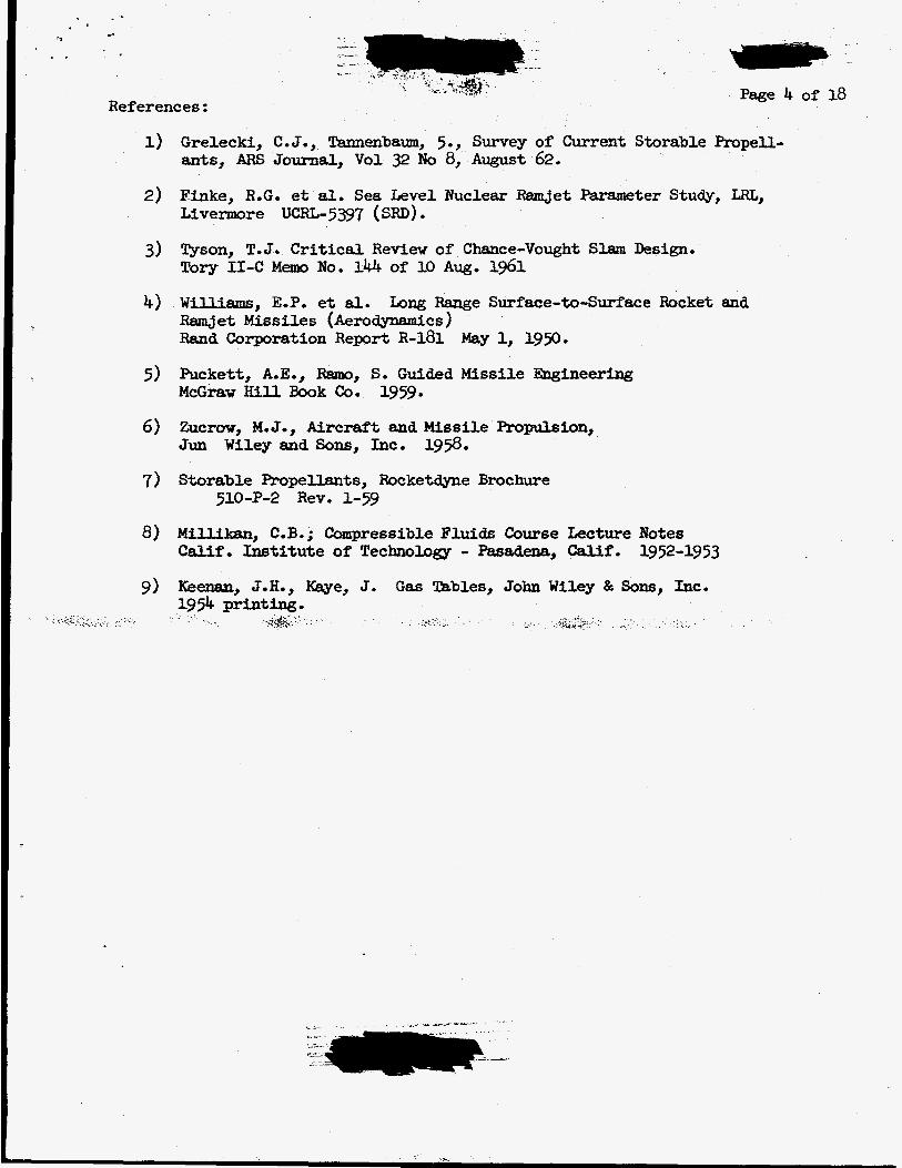
Grelecki, C.J., Tannenb8m, 5., Survey of Current Storable Propell- ants, ARS Journal, Vol 32 No 8, August 62,
Finke, ROC. et al. Sea Level EJuclear RmJet Parameter Study, LRL, Livermore ~ ~ ~ 1 4 - 5 3 9 7 ( SRD) . Tyson, T.J. Critical R e v i e w of Chance-Vought Slam Design. TOW II-C M e m ~ NO. 144 of 10 Au~. 1961
Williams, E.P. et 81. Long Range Surface-to-Surface Rocket and w e t Mssiles (Aerodynamics) Rand Corporation Repart R-181 May 1, 1950.
Puckett, A.E., Ram, S. Guided Missile mineering M c G ~ w Hill Book C o o 1959.
Zucrov, M.J., Aircraft and Missile Propulsion, Jun Wiley and Sons, Inc. 19%.
Storable Propellants, Rocketdyne Brochure 5U)-P-2 Rev. 1-59
Milliksn, C.B.; Compressible Fluids Course Lecture Notes Calif, Institute of Technology - Pasadena, Calif, 1952-1953
Keenan, J.H., w e , J. Gas Tables, John Wiley & Sons, Inc. 1954 printing-
.,-.
c. . ,*. .
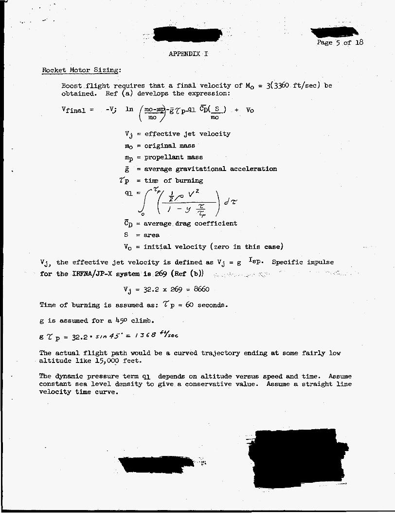
Rocket Motor Sizing:
APPENDIX I
Boost-flight requ,:es that a f ina l veloc ty of 1, = obtained. Ref (a) develops t h e expression:
Page 5 of 18
V j = effective Jet velocity Q = original mass % = propellant mass ,Zj = average gravitational acceleration
r p = t i m of burning
. . ..
(3360 ft/sec) be
- CD = average drag coefficient S =area Vo = i n i t i a l velocity (zero in t h i s case)
V j , the effec-bfve j e t velocity is defined as V j = g
for the IRFNA/Jp-X system is 269 (Ref (b))
‘SP* Specific impulse .
V j = 32.2 x 269 = 8660
Time of burning is assumed as: T p = 60 seconds.
g is assumed f o r a 450 climb.
g = 32.2 s / f i 43-* = I 3 6 8 ‘%C
The actual f l i gh t path would be a curved trajectory ending at some fa i r ly low a l t i tude l ike 15,000 feet.
The dynamic pressure term ~1 &pen& on a l t i t u d e versus speed and time. constant sea level density t o give a conservative value. velocity time curve.
Assume Assume a straight l i n e
I e- - * - . .
F .- _ . Page 6 of 18
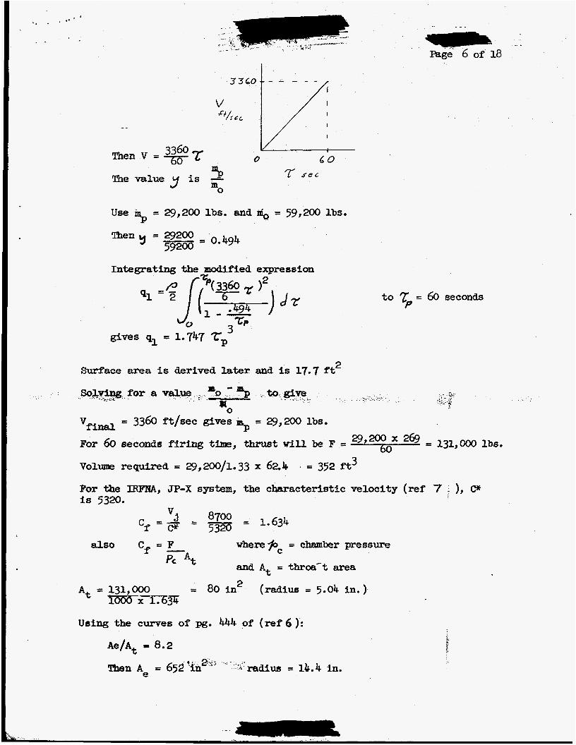
P The value y is - mO
to rp = 60 seconds
gives ql = 1.747 zp’ 2 Surface area is derived later and is 17.7 ft
so for a “0-p to
vfinsl
#O = 3360 ft/sec gives pSp = 29,200 lbs.
29,y as = 131,000 lbs. For 60 seconds firfag time, thrust W i l l be F = 0
Vel- required = 29,200/1.33 x 624 . = 352 ft3
For the IEWXW, JP-X system, the characteristic velocity (ref 7 - ), CY is 5320.
also Cf = F where&= = chamber pressure - and At = throa’t area
2
Pc At
= 80 in (radius = 5.04 in.) A% = 131,000 lo00 x 1,634
Using the curves of pg. 444 of (ref 6 ):
Ae/At - 8.2
Then A~ = 652‘in 2 i., ”. . .I radius = 11.4 in.
For
the
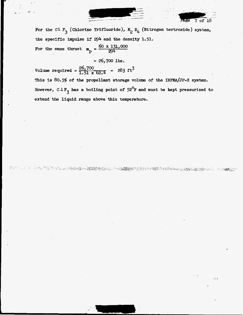
For
the C1 F (Chlorine Trifluoride), N2 H4 (Nitrogen tertroxide) system, 3 specific impulse if 294 and the density 1.51.
60 x 131,000 294
thesamethrust m = P .-
= 26,700 lbs.
26,700 = 283 f t 3 1.51 x 62.4 Volume required =
This is 80.5$ of the propellant storage volume of the IRFNA/JP-X system.
However, C I F has a boiling point of 52OF and must be kept presrmrized to
extend the liquid range above this t e m p e r a . t u r e . 3
.: i(. .. ..;. . . . . .-. . ~ . , . . . . .
APPENDIX I1
Flight conditions :
Mo = 3.0
Altitude - sea level
Temperature - 60°F Scaling f r o m !bry I I C for afrflaw
M2 542 - x 1800 = 1425 lbs/sec
In- Area = 1400 $v -.002378 x 32.2 x 3360
- - Ai -
2 = 5.45 ft
2 Refel-ence Area = 14.72 ft (52 in. dia. missile)
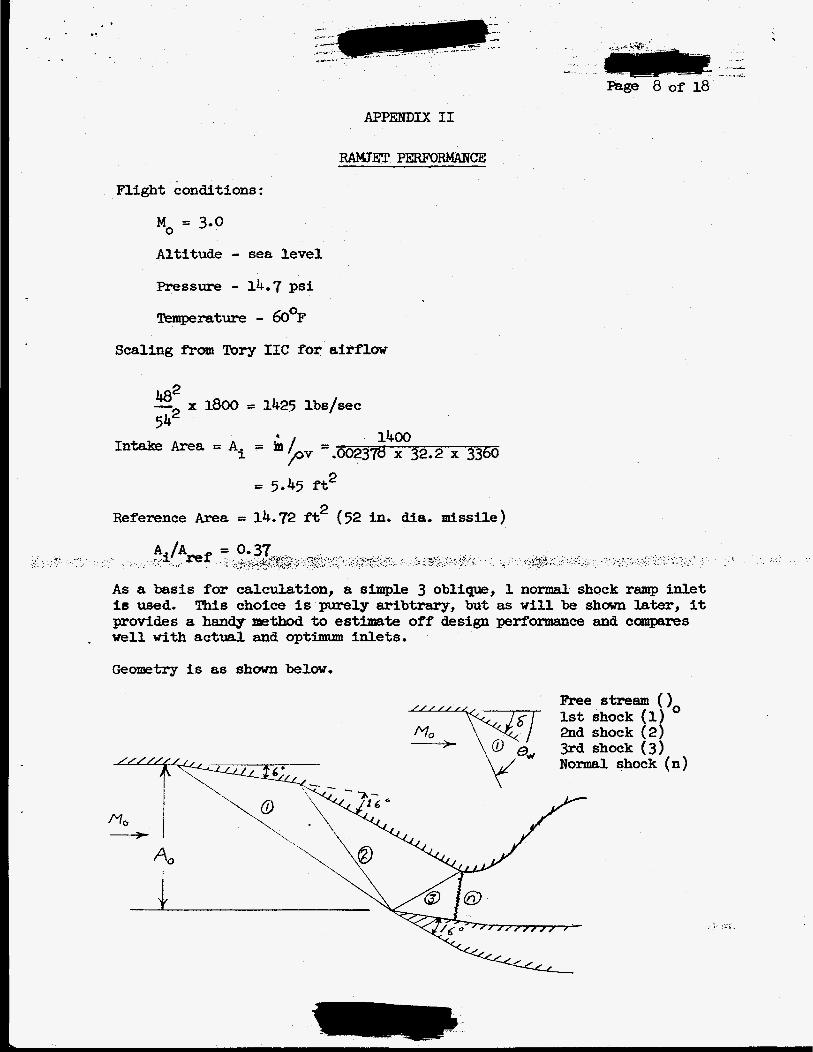
As a basis for calculation, a simple 3 obliqpe, 1 normal shock ramp inlet is used, This choice is purely aribtrary, but as w i l l be shown later, it provides a handy n&zthod to estfmate off design perf'onnance and cornpares w e l l with actual and optimum inlets.
Geometry is as shown below.
m e stream (), 1st shock (1) 2nd shock (2) 3rd shock (3) Normal shock (n)
I. ,(r .
PEL& 9 of 18
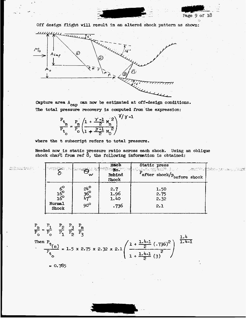
O f f design fl ight w i l l result i n an altered shock pattern as shown:
Capture area A The total pressure recovery is computed fmmthe expression:
can now be estimated at off-design conditions, C a p
where the t subscript refers to total pressure.
Needed now is static pressure ratio across each shock, shock
Using an oblique from ref 8, the following infomation is obtained:
f 6 O 160 160 x Shock
*n p1 p2 p3 pn Po Po p1 p2 p3 - = - - - - Then P,
2.7 1.96 1.40 -736
1-50
2-32 2- 15
2.1 I
1-4 / 1 + ( ~ 3 6 ) ~ ) 1.4-1
. . Page 10 of 18- +
For Mo = 2.5 a similar calculation yields a pressure rat io of 0.824 and ACap/Ao = 0.834. oblique and 1 normal shock conical diffisera and about 0.75 for 2 oblique and 1 normal shock. Properly, a variable dshould be used t o account for tempera- ture changes, Throughout the remainder of these calculations, an average 2f
is used based on the temperature into and aut of the applicable section being considered.
R e f . 6 gives a pressure recovery of about 0.84 for 3
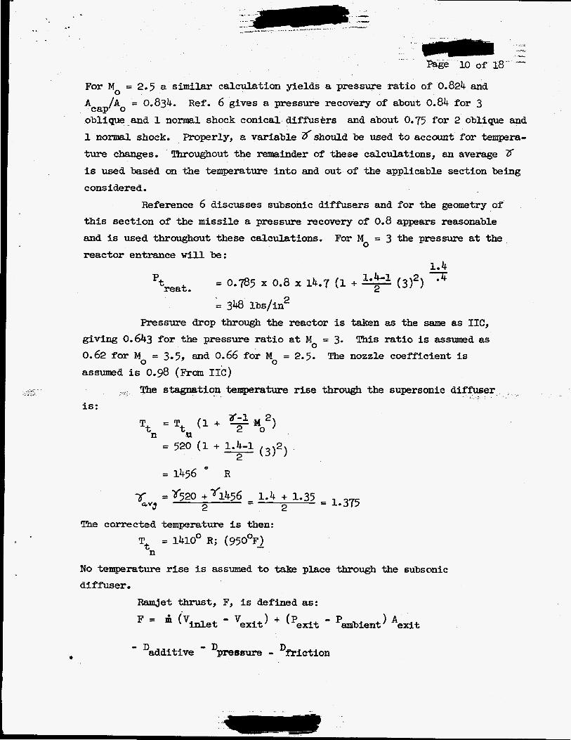
Reference 6 discusses subsonic diffusers and for the geometry of this section of the m i s s i l e a pressure Fecovery of 0.8 appears reasonable and is used throughout these calculations. reactor entrance will be:
For Mo = 3 the pressure at the
2 = 348 lbs/in Pressure drop through the reactor is taken as the same as I I C ,
This ra t io is assumed as giving O.6h3 for the pressure ratio a t Mo = 3. 0.62 for Mo = 3.5, and 0.66 for Mo = 2.5. assumed is 0.9 (From IIC)
The nozzle coefficient is
The stagnation temperature rise through the supersonic diff'user . is:
8-1 2 Tt = Tt (1 + 7 Mo ) n rn
(312) = 520 (1 + 1.4-1 - 2
O
= 1456 R
The corrected temperature is then: = 1410° R; (95OOF) -
n Tt
N o tempera ture rise is assumed t o t a b place through the subsonic diffuser .
met thrust, F, is defined as:
F = ' ('inlet 'exit) + ('exit - 'ambient) *exit
'additive - Dpressure - Dfriction
*-. . .
. . Page of 18
.
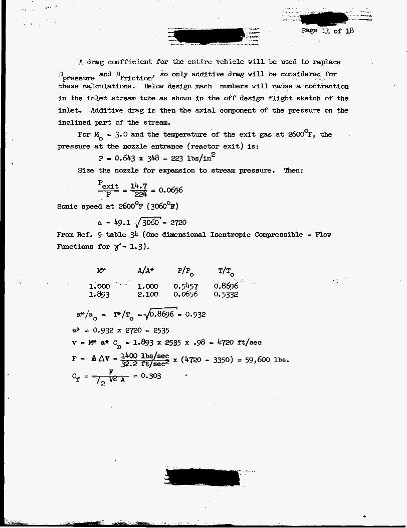
A drag coefficient for the ent i re vehicle w i l l be used to replace so only additive drag will be considered f o r 'pressure and DfrictionJ
these calculations, Below design mach numbers w i l l cause i n the inlet stream tube as shown i n the off design fl ight sketch of the inlet.
inclined part of the stream. Additive drag is then the axial component of the pressure on the
For Mo = 3.0 and the temperature of the exit gas at 2600°F, the pressure a t the nozzle entrance (reactor ex i t ) is:
P = 0,643 x 348 = 223 lbs/in2
Size the nozzle for expansion to stmasn pressure, lhen:
Sonic speed at 2600°F (3060OR)
a = 49,l -/-= 2720 From Ref . 9 table 34 (One dimensional Isentrapfc Compressible - Flow Functions for r= 1-3)~
. .-
c
L* _. . .
. . . . . . . . . . _.-.. .... .._ci. ..... ..,_ ..._.-.... . . . ----.--a_(-.
Page 12 of 18
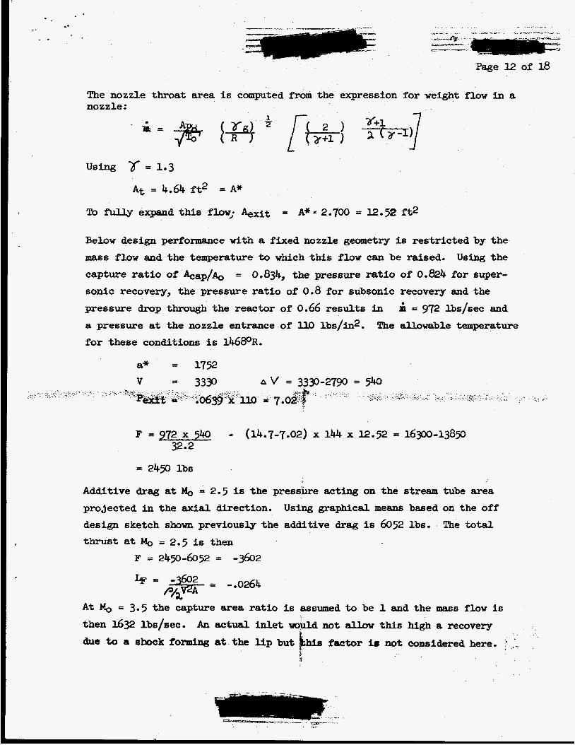
The nozzle throat area is computed from the expression for weight flow i n a nozzle:
Using = 1.3
A t = 4.64 ft2 = A*
To fully expand this flow; +it = A** 2.700 = 12.52 f't2
Below design performance with a fixed nozzle geometry is restricted by the
mass flow and the temperature to which this flow can be raised. Using the capture ratio of &ap/&, = 0.834, the pressure ratio of 0.824 for super- sonic recovery, the pressure ratio of 0.8 for subsonic recovery and the pressure drop through the reactor of' 0.66 results i n 4 = 972 lbs/sec and
a pressure at the nozzle entrance of U.0 lbs/in2. for these conditions is 1468oR.
The allowable temperature
F = 972 x 540 - (14.7-7.02) x 144 x 12.52 = 16300-13850 32.2
= 2450 lbs
Additive drag at & = 2.5 is the pressure acting on the stream tube area proJected i n the axial direction. Using graphical means bssed on the off design sketch shown previously the additive drag is 6052 lbs.
thrust at MO = 2.5 is then The total
F = 249-6052 = -3602
A t M, = 3.5 the capture area ratio is assumed t o be 1 and t h e mass flow is then 1632 lbs/sec. due to a shock fomdng at the U p but lhis faator 16 not considered here. ,' :.
An actual inlet would not allow this high a recovery
i
.* .. . .
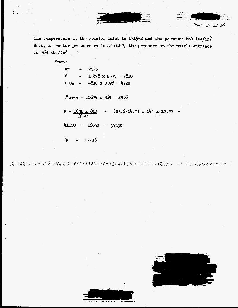
Page 13 of 18
The temperature at the reactor inlet is 1719R and the pressure 660 lbs/in? Using a reactor pressure ratio of 0.62, the pressure at the nozzle entrance
is 369 Ibs/in2
Then:
a* = 2535
v c, = 4.810 x 0.9 = 4720 V = 1.898 x 2535 = 4810
CF = 0.216
..-
...__-_ - - _ - , -
Page 14 of 18 e
Vehicle Structure and Stores
The schematic vehicle outlined in Figure 1 has a net length of 30 feet in the liquid propellant launched version and 26-& feet in the hybrid solid launched variation. The overall body diameter of both versions is 52 inches. The estimated flight weight of the vehicle is 27,500 Ibs., t 1,p lbs.
Vehicle Structure
The fuselage structure is assumed to consist of three primaryportions. The foreward most postion extending aft to the region of Fuselage Station 164 consists of the inlet plus weapons and guidance bays. The structure of this portion is assumed to be fabricated in a conventional skin- stringer-bulkhead fashion of precipitation hardening high temperature alloy and is unpressurized.
-
The mid section of the fuselage extending from approximately Fuselage Station 164 to Fuselage Station 316 is an integrally stiffened skin pressure vessel with fore and aft ring bulkheads.
This region contains the reactor power plant, inlet plenum, reactor control and coolan& storage bays, and an integral. radiation shadow shield. Structural weights quoted are based on the use of solid solution high temperature alloys.
The rearmst structural division consists of the exit nozzle, boat-tail fairing and l i f t ing surface erection actuator bay. The construction is presumed to consist of a monolithic nozzle supplanted by a web supported fairing shell.
The lifting and stabilizing surfaces shown are a simple single fold design of arbitrary plan form. net area of a hypothetical delta configuration would approximate 45 square feet
The --span projection is on the order of 4 feet. The
All structural estimates were based on O-l$ strain in 10 hours at 1000°F material strength extrapolated from published data. factor used was 1.25.
The design safety
Reactor
The reactor configurations shown are rear supported designs requiring no internal metal structure. The primary configuration makes use of a "dome" l ike axial support of self bondedailicon carbide such as have recently been fabricated and tested by LRL.
The auxillieuy configuration shown makes use of an internally air cooled metal supprt structure incorporating multiple fuu. expansion nozzles. In each instance, the reactor is capable of being separated completely from the vehicle systems and structure. occur at the axial support structure seat and foreward shear joint. reactor w e i g h t s detailed below a-e based on a &inch overall ceramic matrix diameter, 40-inch fueled matrix diameter, silicon carbide "dome" supported Be0 core assembly.
The sole mechanical attachments The
Systems, Awrilliaries and Stores
1. Weapons: Optional configurations range f r o m a single Z-inch dirt- meter-& or pa€r of =-inch diameter warheads t o as many as six l5-inch diameter ejectable weapons. cubic feet. 1Q megatons.
The net volume of In each variant the total yield should be
2. Shielding: Provision is made for m8ss attenuation radiation seen by the main guidance and weapons bays. visions for scatter shielding may be necessary but was th i s treatment.
3. Guidance: The foreward guidance bay is assumed t o
the bay is 45- on the order of
of direct beam Additional pro- not considered i n
. - .~ house antennae and
other receptors along with the canard control surface actuators. available volume is about 6 cu f t . ume of about 18 cu ft and is presumed to house all active electronic and radiation sensitive control systems.
The net The main (e) guidance bay has a vol-
4. Reactor Control Actuators: Radiation resistant control rod servo and "scrarm" actuators are housed i n a nacelle projecting in to the inlet plenum.
5. Coolant: based on is arbitrari ly sized at 5 cu f t .
Provision for an evaporative or mechanical coolant system is a presumed requirement of the guidance and/or weapons systems and
Weight Sumnary
The following brief summsry of weights is derived from calculations based on the foregoing considerations. servative, i-e. a l i t t l e on the high side.
The numbers quoted are intended t o be con-
Weight Summary ( Continued)
1. Reactor:
ceramic matrix, 46" dia. - 60" long Axial support structure, Sic dome Front preload structure & f i t t ings Side support structure & f i t t ings Integral control hardware Dome seat support structure
2. Air Frame:
Nose & M e t t o fuse sta. 164 Main fuselage - F.S. 164 t o F.S. 3 6 Nozzle & boat-tail-aft of F-S. 316 W i n g and erecting mechanism
3. Other:
Weapons stores Shadow shield Fwd. guidance bay
A f t guidance bay Reactor controls c o o h t system
8,150 l b
Total Flight Weight
PROPOSED I M U L T l h f NOZZLE VEHICLE CCNFWRATIDM WITH HYBRID SOLID WTER
F.B.M. NUCLEAR SUBMARINE WNCHTUBE PROnLE L. \ _.
FOLDED
.A ... I
i
! # I j --f , , 1 ;
. ........ ............. ..J ...... .. -
. , . . . !;- ...... ! , , ~ : . . . . . ..-: . .~
I
. .
. . . . . . .
- - - I - 1 .- - - T I