Embed Size (px)
Citation preview
Noname manuscript No.(will be inserted by the editor)
A Planning Approach to the Automated Synthesis ofTemplate-Based Process Models
Andrea Marrella · Yves Lesperance
Received: date / Accepted: date
Abstract The design-time specification of flexible pro-
cesses can be time-consuming and error-prone, due to
the high number of tasks involved and their context-
dependent nature. Such processes frequently suffer from
potential interference among their constituents, since
resources are usually shared by the process participants
and it is difficult to foresee all the potential tasks inter-
actions in advance. Concurrent tasks may not be inde-
pendent from each other (e.g., they could operate on the
same data at the same time), resulting in incorrect out-
comes. To tackle these issues, we propose an approach
for the automated synthesis of a library of template-
based process models that achieve goals in dynamic
and partially specified environments. The approach is
based on a declarative problem definition and partial-
order planning algorithms for template generation. Theresulting templates guarantee sound concurrency in the
execution of their activities and are reusable in a vari-
ety of partially specified contextual environments. As
running example, a disaster response scenario is given.
The approach is backed by a formal model and has been
tested in experiments.
Keywords Flexible Processes, Template-based
Process Models, Partial-Order Planning, Business
Process Management
A. MarrellaSapienza - Universita di Roma, ItalyE-mail: [email protected]
Y. LesperanceYork University, Toronto, CanadaE-mail: [email protected]
1 Introduction
Over the last decade, organizations and companies
have started adopting process management method-
ologies and tools, with the aim of increasing the level
of automation support for their operational business
processes. Business Process Management (BPM) has,
therefore, become a leading research area in the broader
field of information systems [2].
Conventional BPM solutions require us to pre-define
a detailed model of the process which completely pre-
scribes the process execution flow and captures every
possible process instance to be executed at run-time
through a Process Management System (PMS). These
models, typically based on imperative process speci-
fication, allow for a complete predefined specification
of process logic able to represent procedural process
knowledge, capturing the tasks to be executed and their
control-flow, as well as process-related data and organi-
zational perspectives [24]. Examples of traditional busi-
ness processes include insurance claim processing, order
handling, administrative processes, etc.
In recent years, the maturity of process manage-
ment methodologies and of PMSs has lead to the appli-
cation of BPM approaches in new challenging dynamic
and knowledge-intensive scenarios [69,18], such as do-
motics [33], healthcare [47], projects coordination [19]
and emergency management [57]. In these working envi-
ronments, most business functions involve collaborative
features and semi-structured (or unstructured) proce-
dures that do not have the same level of predictability
as the routine structured work.
This has lead to the definition of a new class of flex-
ible processes [69]. Processes are defined as “flexible”
when people/agents carry them out with a fair degree
of “uncertainty”, where the uncertainty may depend on
2 Andrea Marrella, Yves Lesperance
many factors, such as the high number of tasks to be
represented, their unpredictable nature, or their depen-
dency on the contextual scenario. In a flexible process,
the sequence of tasks depends heavily on the specifics
of the context (e.g., which resources are available and
what particular options exist at the time), and it is of-
ten unpredictable how the process will unfold.
While there exist several approaches supporting the
enactment and automated adaptation of flexible pro-
cesses at run-time [69,29,52,54,57,55,9,56], the design-
time specification of such processes can be difficult,
time-consuming and error-prone. Flexible processes fre-
quently suffer from potential interference among their
constituents, since resources are usually shared by the
process participants and it is difficult to foresee all
the potential tasks interactions in advance. Moreover,
the process designer often lacks the needed knowledge
to anticipate and incorporate all potential alternatives
into the process model at design-time, as well this
knowledge can become obsolete as process instances are
executed and the context evolves. As a consequence,
flexible processes may include some underspecified ac-
tivities whose exact definition is not yet known at
design-time, and may not be known until the time that
an instance of the process has started execution, due
to their context-dependent nature. In the worst case,
there is no pre-defined view of a flexible process.
To tackle this issue, in this paper we build upon
our previous work [51] and present a planning-based
approach to the automated synthesis of template-based
process models starting from a representation of the
contextual domain in which a flexible process is em-
bedded in and from an extensive repertoire of tasks
defined for such a context. We refer to the concept of
process templates to emphasize that further refinements
may be needed to actually implement a flexible process.
A process template depicts the best-practice procedure
drawn up with whatever contextual information avail-
able at the time; it describes a recommended control
flow for the process that does not only work in a spe-
cific state of the world, but can be enacted in a range
of states satisfying the context conditions.
Specifically, we advocate a modeling approach in-
volving a declarative specification of process tasks. We
annotate process tasks with preconditions and effects
defined over the contextual data of the dynamic sce-
nario, i.e., we consider tasks as single steps that con-
sume input data and produce output data. Then, we
propose to use partial-order planning algorithms (aka
POP [81,62]) to dynamically generate process tem-
plates based on descriptions of the initial state of the
world and of a goal condition to be achieved through the
execution of the template. A state-of-the-art partial-
order planner is fed with task descriptions, initial state
and goal condition, and returns a process template
that satisfies the specification. The use of POP algo-
rithms and, in general, of automated planning tech-
niques, guarantee some interesting properties in the
construction of the template:
– Contextual selection. Tasks composing the template
are contextually selected from a specific repository
and partially ordered in a way consistent with the
context conditions to ensure that the template’s ob-
jectives are achieved.
– Sound concurrency. Concurrent activities of a pro-
cess template are proven to be effectively indepen-
dent one from another (i.e., concurrent tasks cannot
affect the same data). This means more flexibility
during process execution. At run-time, the most ap-
propriate execution path can be selected from those
allowed by the design-time process template defini-
tion, without the risk of interference between con-
current tasks.
– Executability in partially specified environments.
Once synthesized, a template can be executed in
several initial states, since it (usually) requires a
fragment of the knowledge of the initial state to
successfully achieve its objectives. We identify the
weakest preconditions of process templates, and all
the states satisfying such preconditions are good
candidates for executing them.
– Versatility. Our approach allows to represent the
problem of synthesizing a process template as a
planning problem in the standard Planning Do-
main Definition Language [58] (PDDL [58]), which
can be solved through off-the-shelf automated plan-
ners. Since PDDL is independent from the specific
planning system employed, one can seamlessly in-
tegrate different state-of-the-art planners compliant
with PDDL. The effort to integrate a different plan-
ner does not go beyond installing the new planner
and loading the planning-problem formulation that
is generated through our planning-based approach.
The problem formulation remains unchanged when
moving from one planner to the other.
We exploit the idea behind POP of representing
flexible plans that enable deferring decisions. Instead
of committing prematurely to a complete, totally or-
dered sequence of actions, plans are represented as a
partially ordered set, and only the required ordering
decisions are recorded. A process template is generated
on the basis of such a partially ordered set of activi-
ties, and we are able to identify what knowledge about
the initial state is required for successful template ex-
ecution. Moreover, we propose a methodology to build
step-by-step a library of process template specifications
A Planning Approach to the Automated Synthesis of Template-Based Process Models 3
and support efficient retrieval of appropriate templates
from the library in partially specified environments.
The rest of the paper is organized as follows. Sec-
tion 2 presents a running example describing a flexible
process that comes from the emergency management
domain. Section 3 introduces the required background
and preliminaries for our work. Section 4 describes the
basic ingredients for modeling the contextual properties
of a dynamic environment, and introduces formally the
concept of process template. Section 5 discusses in de-
tail our approach to synthesize a library of process tem-
plates. A prototypical implementation of our approach
is presented in Section 6, together with a set of exper-
imental evaluation results that assess the practical ap-
plicability of our approach to design flexible processes.
Section 7 discusses related work and Section 8 concludes
by discussing benefits, limitations and future develop-
ments of the approach. Finally, an Appendix gives some
technical details about the algorithms used for comput-
ing process templates.
2 Running Example
In the emergency management domain, teams of first
responders act in disaster locations with the main pur-
pose of achieving specific goals, including assisting po-
tential victims and assessing and stabilizing the situa-
tion. First responders can benefit from the use of mo-
bile devices and wireless communication technologies,
as well as from the adoption of a process-oriented ap-
proach for team coordination. A response plan encoded
as a business process and executed by a PMS deployed
on mobile devices can help to coordinate the activi-
ties of first responders equipped with smartphones and
supported by mobile networks. The use of business pro-
cesses for coordinating first responders in disaster sce-
narios has been investigated in the European project
WORKPAD1 [12,39,40,11,53]. The following running
example, which represents an excerpt of a real case
study on emergency management investigated within
the WORKPAD project, will be used to illustrate our
approach to the synthesis of process templates.
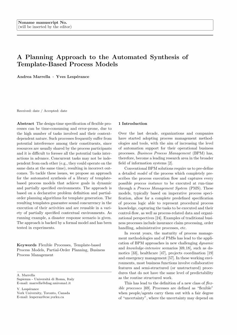
Let us consider the disaster scenario described in
Fig. 1(a). It concerns a train derailment and depicts
a map of the area (as a 4x4 grid of locations) where
the disaster happened. We suppose that the train is
composed of a locomotive (located in loc33 ) and two
coaches (located in loc32 and loc31 respectively). The
goal of an incident response plan defined for such a
context is to evacuate people from the coach located in
1 http://www.diag.uniroma1.it/~workpad/
Fig. 1: Area and context of the intervention.
loc32, to extinguish a fire in the coach in loc31 and fi-
nally to take pictures for evaluating possible damages to
the locomotive, located in loc33. Thus, a response team
can be sent to the derailment scene. The team is com-
posed of four first responders (in the remainder, we refer
to them as actors) and two robots, initially located in
loc00. We assume that actors are equipped with mobile
devices (for picking up and executing tasks) and provide
specific capabilities. For example, actor act1 is able to
extinguish fires, while act2 and act3 can evacuate peo-
ple from train coaches. The two robots, instead, may
take pictures and remove debris from specific locations.
Each robot has a battery and each action consumes a
given amount of battery charge. When the battery of a
robot is discharged, actor act4 can charge it. Fig. 1(b)
summarizes the above.
The definition of an incident response plan as a busi-
ness process involves a dynamically selected set of ac-tivities to be executed on the field by the first respon-
ders. Since the process may be different every time it is
defined because it strictly depends on the actual con-
textual information (the positions of actors/robots, the
battery level of robots, etc.), it is unrealistic to assume
that the process designer can pre-define all the possible
process models for dealing with this kind of interven-
tion and environment (apparently simple). Moreover, if
contextual data describing the environment are known,
the synthesis of a process dealing with such an envi-
ronment is not straightforward, as the correctness of
the process is constrained by the values (or combina-
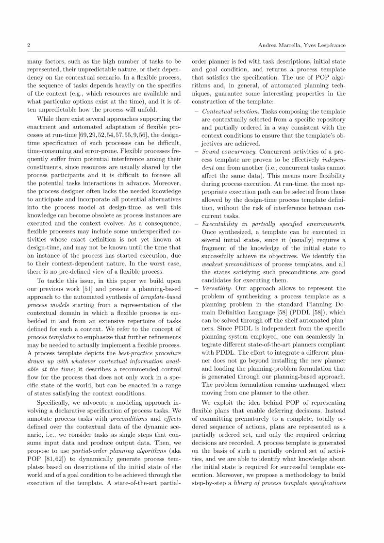
tion of values) of contextual data. A simple approach
to solving our problem is to build a process as a se-
quence of activities, e.g., the sequence of actions shown
in Fig. 2 (solid arrows represent ordering constraints
between actions). The process in Fig. 2 instructs actor
act1 to reach loc31 to extinguish fire. Then, after the
battery of robot rb2 has been recharged by act4, it can
move in loc32 for removing debris and the actor act2
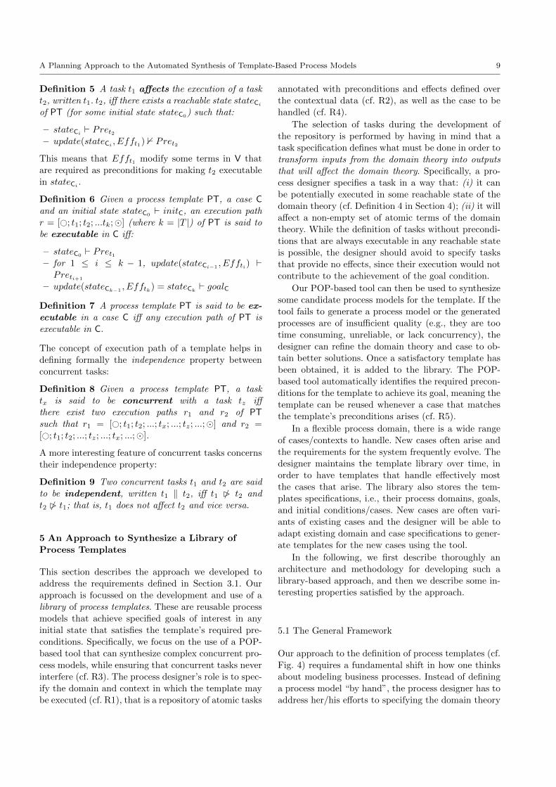
4 Andrea Marrella, Yves Lesperance
Fig. 2: A process dealing with the scenario of Fig. 1.
can start to evacuate people in that location. Finally,
the battery of robot rb1 is recharged as well, and it can
move into loc33 for taking pictures.
However, this solution is highly inefficient, as many
actions are independent, and they could be executed
concurrently to reduce intervention time; e.g., a robot
could take pictures in parallel with the extinguishing of
the fire in loc31. But, at the same time, a process de-
signer may find it difficult to organize activities for con-
current execution, since each action, for its executabil-
ity, depends on the values of contextual data (e.g., a
robot needs enough battery charge for moving into a
location and taking pictures or removing debris). Also
dependencies between actions play a key role in the def-
inition of the process model (e.g., in order to evacuate
people at loc32, a robot must have removed the debris
beforehand). Finally, a process designer tends to rep-
resent more contextual information than that strictly
needed for defining a process. For example, the pro-
cess in Fig. 2 does not involve actor act3, meaning that
any information concerning act3 (e.g., its capabilities,
its location, etc.) is not required for synthesizing and
executing the process.
3 Background
In this section, we present the required background and
preliminaries for our work. Specifically, in Section 3.1
we discuss the main characteristics underlying a flexible
process and describe some high-level requirements that
have to be fulfilled for its design, while in Section 3.2
we introduce the basic notions on partial-order planning
necessary to understand the rest of the paper
3.1 Characteristics and Requirements for Designing
Flexible Processes
Over the last decade, BPM research has been ex-
panded in many emerging directions, to support pro-
cess mining [3], service-oriented computing [64], case
management [75], cognitive computing [37], knowledge-
intensive processes [18] and flexible processes [69].
The latter may be considered as specific cases of
knowledge-intensive processes. According to [18], where
they are called “dynamic processes”, flexible processes
are seen as “fragments of larger unstructured processes
[...] whose tasks need to be dynamically selected (or gen-
erated) at run-time”. In addition, according to [69],
these processes are implicitly described in text or other
forms of abstract procedures rather than explicitly
modeled, i.e., they are often described directly by their
process instances, by making the separation between
process model and process instance largely blurred or
non-existent.
In Section 2 we have presented an example of a flex-
ible process coming from the emergency management
domain. Starting from the experience gained in the area
and lessons learned from the WORKPAD project and
from the extensive analysis on flexible processes per-
formed in [69,18], in the following we present the main
characteristics underlying a flexible process to be en-
acted in a dynamic real-world scenario:
– [C1] Loosely structured behavior. The set of possi-
ble activities may be known and predefined, but
their execution ordering is not rigidly pre-definable
as many possible execution alternatives are allowed.
– [C2] Data- and Constraint-driven. The main driver
for the process progression is not (only) given by
activity completions, but rather by the availability
and evolution of data and knowledge objects (e.g.,
for representing contextual properties of a dynamic
environment), which drive human decision making
and directly influence the flow of process actions and
events. Sometimes, data objects are used for defin-
ing constraints acting as eligibility criteria and pre-
conditions for selecting the activity to be executed
at run-time and the data sources to be exploited.
– [C3] Unpredictable. The exact activities and con-
trol flow in a flexible process depends on situation-
and context-specific parameters, whose values may
not be known a priori, may change during process
execution, and may vary over different process in-
stances. As a consequence, any detailed and fine-
grained control-flow modeling attempt for flexible
processes may become useless and inefficient.
– [C4] Goal-oriented. Usually, a flexible process
evolves through a series of intermediate goals or
milestones to be achieved. These goals may be
known a priori and predefined, or, they may be
gradually defined as a result of acquired knowledge
and previously achieved goals. Each performed ac-
tion and decision taken towards the achievement
of a given goal has the effect of producing knowl-
edge that will be exploited for supporting subse-
quent decisions and determining the next goals to
be achieved and actions to be executed. Moreover,
goals may be modified or even invalidated as a con-
sequence of an event occurrence that has an impact
on the process state and execution context.
A Planning Approach to the Automated Synthesis of Template-Based Process Models 5
The above characteristics are related to both the model-
ing and execution phases of a flexible process. However,
in this paper, we mainly focus on the modeling phase.
Specifically, we present an approach for the declarative
modeling of contextual data and process tasks, and for
automatically synthesizing a library of template-based
process models ready to be enacted in contextual sce-
narios. Many of the aspects related to the execution of
a flexible process are out of the scope of this paper, and
there exists a vast research literature on the topic [69,
29,52,54,57,55,9,56].
To this end, starting from the above characteristics,
we derive and define a set of 5 high-level requirements
related to flexible process modeling:
– [R1] Modeling contextual data. A strong requirement
for flexible processes is to provide an information
model including all relevant data affecting the pro-
cess and manipulated by it. Contextual data need
be formalized and encoded in some form of domain
theory, so as to define data objects to be considered
as part of the process context and execution state.
A process designer should also be allowed to express
conditions over process data, if needed.
– [R2] Representing data-driven activities. A flexible
process is characterized by activities whose enact-
ment is related to the evolution of the information
model. Such activities must be enriched with declar-
ative elements and constraints (e.g., pre and post-
conditions) defined on contextual data, stating what
data may constrain the process execution or may be
affected after an activity completion.
– [R3] Providing synchronized access to shared data.
To prevent process tasks for possibly accessing and
modifying the same data at the same time, it is re-
quired to provide some form of synchronized access
to shared data.
– [R4] Defining process goals. The process designer
should be able to define process goals on the basis
of the contextual data defined for the process.
– [R5] Modeling for reuse. Even if a flexible process is
often unpredictable, with the models of two process
instances that may differ from one another, this does
not exclude the possibility of predefining common
fragments of the process models and deriving process
templates to be reused, selected and adapted in a
context-dependent way.
In Section 5, we show how our planning approach
to synthesize process templates allows to properly ad-
dress the above requirements. We recognize that there
are other modeling approaches in the research litera-
ture that are able to (partially and fully) deal with the
requirements: We investigate them in Section 7.
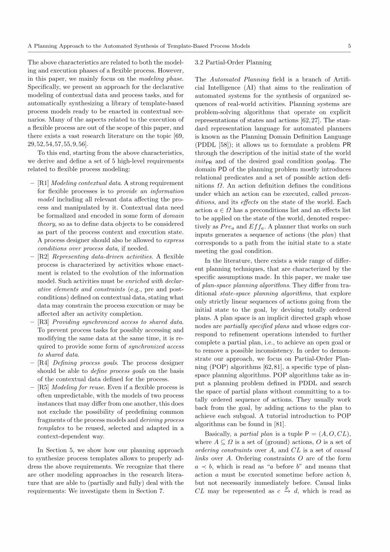
3.2 Partial-Order Planning
The Automated Planning field is a branch of Artifi-
cial Intelligence (AI) that aims to the realization of
automated systems for the synthesis of organized se-
quences of real-world activities. Planning systems are
problem-solving algorithms that operate on explicit
representations of states and actions [62,27]. The stan-
dard representation language for automated planners
is known as the Planning Domain Definition Language
(PDDL [58]); it allows us to formulate a problem PRthrough the description of the initial state of the world
initPR and of the desired goal condition goalPR. The
domain PD of the planning problem mostly introduces
relational predicates and a set of possible action defi-
nitions Ω. An action definition defines the conditions
under which an action can be executed, called precon-
ditions, and its effects on the state of the world. Each
action a ∈ Ω has a preconditions list and an effects list
to be applied on the state of the world, denoted respec-
tively as Prea and Effa. A planner that works on such
inputs generates a sequence of actions (the plan) that
corresponds to a path from the initial state to a state
meeting the goal condition.
In the literature, there exists a wide range of differ-
ent planning techniques, that are characterized by the
specific assumptions made. In this paper, we make use
of plan-space planning algorithms. They differ from tra-
ditional state-space planning algorithms, that explore
only strictly linear sequences of actions going from the
initial state to the goal, by devising totally ordered
plans. A plan space is an implicit directed graph whose
nodes are partially specified plans and whose edges cor-
respond to refinement operations intended to further
complete a partial plan, i.e., to achieve an open goal or
to remove a possible inconsistency. In order to demon-
strate our approach, we focus on Partial-Order Plan-
ning (POP) algorithms [62,81], a specific type of plan-
space planning algorithms. POP algorithms take as in-
put a planning problem defined in PDDL and search
the space of partial plans without committing to a to-
tally ordered sequence of actions. They usually work
back from the goal, by adding actions to the plan to
achieve each subgoal. A tutorial introduction to POP
algorithms can be found in [81].
Basically, a partial plan is a tuple P = (A,O,CL),
where A ⊆ Ω is a set of (ground) actions, O is a set of
ordering constraints over A, and CL is a set of causal
links over A. Ordering constraints O are of the form
a ≺ b, which is read as “a before b” and means that
action a must be executed sometime before action b,
but not necessarily immediately before. Causal links
CL may be represented as cp−→ d, which is read as
6 Andrea Marrella, Yves Lesperance
“c achieves p for d” and means that p is an effect of
action c and a precondition for action d. It also asserts
that p must remain true from the time of action c to
the time of action d. In other words, the plan may not
be extended by adding a new action that conflicts with
the causal link and makes p false between c and d. A
precondition without a causal link requires further re-
finement to the plan to establish it, and is considered to
be an open condition in the partial plan. Loosely speak-
ing, the open conditions are preconditions of actions in
the partial plan which have not yet been achieved in the
current partial plan. More formally, an open condition
is of the form (p, a), where p ∈ Prea and a ∈ A, and
there is no causal link bp−→ a (where b is any action of
the partial plan P).
A classical POP algorithm starts with a null par-
tial plan P and keeps refining it until a solution plan
is found. The null partial plan contains two dummy
actions a0 ≺ a∞ where the preconditions of a∞ corre-
spond to the top level goals goalPR of the problem, and
the effects of a0 correspond to the conditions in initPR.
Intuitively, a refinement operation avoids adding to the
partial plan any constraints that are not strictly needed
for addressing the refinement objective. This is called
the least commitment principle [81], and its advantage
is that decisions about action ordering are postponed
until a decision is forced; constraints are not added to
a partial plan unless strictly needed, thus guaranteing
flexibility in the execution of the plan and allowing ac-
tions to run concurrently. A consistent plan is defined
as a plan with no cycles in the ordering constraints and
no conflicts with the causal links. A consistent plan with
no open conditions is a solution [81].
4 Process Templates
Our approach for the generation of a process template
requires us to explicitly model the contextual knowl-
edge in which the flexible process is embedded through
some declarative rules (some pre-defined at design-time,
some known just before the synthesis of the template)
and logical constraints expressed in terms of task pre-
conditions and effects. This information is given as in-
put to an external partial-order planner that will be
in charge of building a process template, i.e., a graph
of activities reflecting the flexible process required for
solving the specific contextual problem.
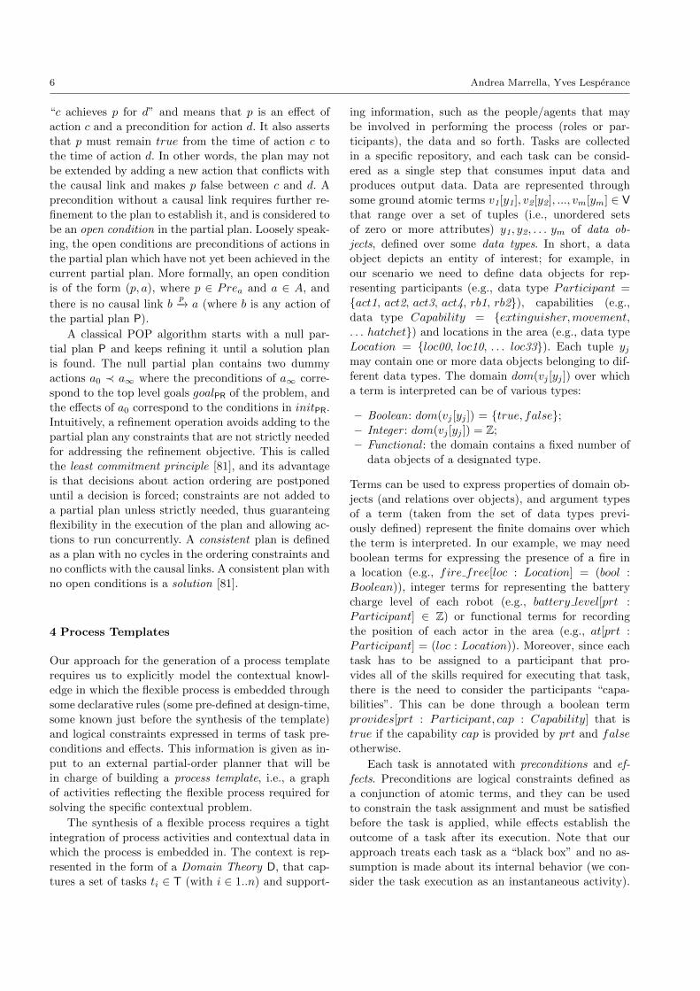
The synthesis of a flexible process requires a tight
integration of process activities and contextual data in
which the process is embedded in. The context is rep-
resented in the form of a Domain Theory D, that cap-
tures a set of tasks ti ∈ T (with i ∈ 1..n) and support-
ing information, such as the people/agents that may
be involved in performing the process (roles or par-
ticipants), the data and so forth. Tasks are collected
in a specific repository, and each task can be consid-
ered as a single step that consumes input data and
produces output data. Data are represented through
some ground atomic terms v1[y1], v2[y2], ..., vm[ym] ∈ Vthat range over a set of tuples (i.e., unordered sets
of zero or more attributes) y1, y2, . . . ym of data ob-
jects, defined over some data types. In short, a data
object depicts an entity of interest; for example, in
our scenario we need to define data objects for rep-
resenting participants (e.g., data type Participant =
act1, act2, act3, act4, rb1, rb2), capabilities (e.g.,
data type Capability = extinguisher,movement,. . . hatchet) and locations in the area (e.g., data type
Location = loc00, loc10, . . . loc33). Each tuple yjmay contain one or more data objects belonging to dif-
ferent data types. The domain dom(vj [yj ]) over which
a term is interpreted can be of various types:
– Boolean: dom(vj [yj ]) = true, false;– Integer : dom(vj [yj ]) = Z;
– Functional : the domain contains a fixed number of
data objects of a designated type.
Terms can be used to express properties of domain ob-
jects (and relations over objects), and argument types
of a term (taken from the set of data types previ-
ously defined) represent the finite domains over which
the term is interpreted. In our example, we may need
boolean terms for expressing the presence of a fire in
a location (e.g., fire free[loc : Location] = (bool :
Boolean)), integer terms for representing the battery
charge level of each robot (e.g., battery level[prt :
Participant] ∈ Z) or functional terms for recording
the position of each actor in the area (e.g., at[prt :
Participant] = (loc : Location)). Moreover, since each
task has to be assigned to a participant that pro-
vides all of the skills required for executing that task,
there is the need to consider the participants “capa-
bilities”. This can be done through a boolean term
provides[prt : Participant, cap : Capability] that is
true if the capability cap is provided by prt and false
otherwise.
Each task is annotated with preconditions and ef-
fects. Preconditions are logical constraints defined as
a conjunction of atomic terms, and they can be used
to constrain the task assignment and must be satisfied
before the task is applied, while effects establish the
outcome of a task after its execution. Note that our
approach treats each task as a “black box” and no as-
sumption is made about its internal behavior (we con-
sider the task execution as an instantaneous activity).

A Planning Approach to the Automated Synthesis of Template-Based Process Models 7
This is not a limitation, since it corresponds to the tra-
ditional way of modelling tasks in the BPM world at
design-time, where nothing is said on the internal be-
haviour of a task (cf. [1,59,24]).
Definition 1 A task t[x] ∈ T consists of:
– the name of the action involved in the enactment of
the task (it often coincides with the task itself);
– a tuple of data objects x as input parameters;
– a set of preconditions Pret, represented as the con-
junction of k atomic conditions defined over some
specific terms, Pret =∧
l∈1..k pretl . Each pretl can
be represented as vj [yj ] op expr, where:
– vj [yj ] ∈ V is an atomic term, with yj ⊆ x, i.e.,
admissible data objects for yj need to be defined
as task input parameters;
– An expr can be a boolean value (if vj is a
boolean term); an input parameter identified by
a data object (if vj is a functional term); an
integer number or an expression involving inte-
ger numbers and/or terms, combined with the
arithmetic operators +,- (if vj is a integer
term);
– op ∈ <,>,==,≤,≥ is a relational opera-
tor. The condition op can be expressed as the
equality (==) between boolean terms or func-
tional terms and an admissible expr. On the
contrary, if vj is a integer term, it is possible
to define the op condition as an expression that
make use of relational binary comparison oper-
ators (<,>,==,≤,≥) and involve integer num-
bers and/or integer terms in the expr field.
– a set of deterministic effects Efft, represented
as the conjunction of h atomic conditions defined
over some specific terms, Efft =∧
l∈1..h efftl .
Each efftl (with l ∈ 1..h) can be represented as
vj [yj ] op expr, where:
– vj [yj ] ∈ V and expr are defined as for precondi-
tions.
– op ∈ =,+=,-= is used for assigning (=) to a
term a value consistent with the expr field or for
incrementing (+ =) or decrementing (− =) an
integer term by that value.
Note that if no preconditions are specified, then the task
is always executable. The use of classical partial-order
planning techniques for synthesizing process templates
imposes some limitation in the expressiveness of the
language used for defining the domain theory D. Specif-
ically, negative preconditions are not admitted (e.g., the
use of the NOT operator is forbidden and all the atomic
conditions that require to evaluate if a boolean term is
equal to false will be ignored) and we assume that all
effects are deterministic.
For example, let us consider the complete specifica-tion of the task Go:
<task>
<name>Go</name>
<parameters>
<arg>actor - Participant</arg>
<arg>from - Location</arg>
<arg>to - Location</arg>
</parameters>
<precondition>at[actor] == from AND
provides[actor,movement] == true
</precondition>
<effect>at[actor] = to</effect>
</task>
It involves two input parameters from and to of type
Location, representing the starting and arrival loca-
tions, and a parameter actor of type Participant, rep-
resenting the first responder that will execute the task.
An instance of Go can be executed only if actor is cur-
rently at the starting location from and provides the
required capabilities for executing the task. As a con-
sequence of task execution, the actor moves from the
starting to the arrival location, and this is reflected by
assigning to the term at[actor] the value to in the effect.
Modeling a business process involves representing
how a business pursues its objectives/goals. The goal
may vary depending on the specific Process Case Cto be handled. A case C reflects an instantiation of the
domain theory D with a starting condition initC and
a goal condition goalC. Both conditions are conjunc-
tions of atomic terms. We do not assume complete in-
formation about initC; this means we allow a process
designer to instantiate only the atomic terms necessary
for representing what is known about the initial state,
i.e., initC = v1[y1] == val1 ∧ ... ∧ vj [yj ] == valj,where valj (with j ∈ 1..m) represents the j-th value
assigned to the j-th atomic term. Fig. 1(b) shows a
portion of initC concerning the scenario depicted in
Fig. 1(a). The goal is a condition represented as a con-
junction of some specific terms we want to make true
through the execution of the process. For example, in
the scenario shown in Section 2, the goal has to be
represented as : goalC = fire free[loc31] == true ∧evacuated[loc32] == true ∧ photo taken[loc33] ==
true. The syntax of goal conditions is the same as for
tasks preconditions.
A state is a complete assignment of values to atomic
terms in V. Given a case C, an intermediate state stateCi
is the result of i tasks performed so far, and atomic
terms in V may be thought of as “properties” of the
world whose values may vary across states.
Definition 2 A task t can be performed in a given
stateCi(and in this case we say that t is executable
8 Andrea Marrella, Yves Lesperance
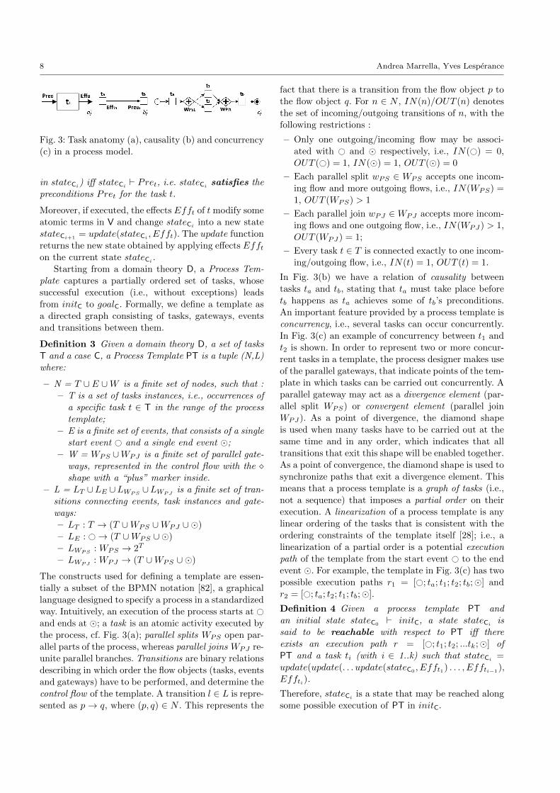
Fig. 3: Task anatomy (a), causality (b) and concurrency
(c) in a process model.
in stateCi) iff stateCi ` Pret, i.e. stateCi satisfies the
preconditions Pret for the task t.
Moreover, if executed, the effects Efft of t modify some
atomic terms in V and change stateCiinto a new state
stateCi+1= update(stateCi
, Efft). The update function
returns the new state obtained by applying effects Effton the current state stateCi
.
Starting from a domain theory D, a Process Tem-
plate captures a partially ordered set of tasks, whose
successful execution (i.e., without exceptions) leads
from initC to goalC. Formally, we define a template as
a directed graph consisting of tasks, gateways, events
and transitions between them.
Definition 3 Given a domain theory D, a set of tasks
T and a case C, a Process Template PT is a tuple (N,L)
where:
– N = T ∪ E ∪W is a finite set of nodes, such that :
– T is a set of tasks instances, i.e., occurrences of
a specific task t ∈ T in the range of the process
template;
– E is a finite set of events, that consists of a single
start event # and a single end event ;
– W = WPS ∪WPJ is a finite set of parallel gate-
ways, represented in the control flow with the shape with a “plus” marker inside.
– L = LT ∪LE ∪LWPS∪LWPJ
is a finite set of tran-
sitions connecting events, task instances and gate-
ways:
– LT : T → (T ∪WPS ∪WPJ ∪ )
– LE : #→ (T ∪WPS ∪ )
– LWPS: WPS → 2T
– LWPJ: WPJ → (T ∪WPS ∪ )
The constructs used for defining a template are essen-
tially a subset of the BPMN notation [82], a graphical
language designed to specify a process in a standardized
way. Intuitively, an execution of the process starts at #and ends at ; a task is an atomic activity executed by
the process, cf. Fig. 3(a); parallel splits WPS open par-
allel parts of the process, whereas parallel joins WPJ re-
unite parallel branches. Transitions are binary relations
describing in which order the flow objects (tasks, events
and gateways) have to be performed, and determine the
control flow of the template. A transition l ∈ L is repre-
sented as p → q, where (p, q) ∈ N . This represents the
fact that there is a transition from the flow object p to
the flow object q. For n ∈ N , IN(n)/OUT (n) denotes
the set of incoming/outgoing transitions of n, with the
following restrictions :
– Only one outgoing/incoming flow may be associ-
ated with # and respectively, i.e., IN(#) = 0,
OUT (#) = 1, IN() = 1, OUT () = 0
– Each parallel split wPS ∈ WPS accepts one incom-
ing flow and more outgoing flows, i.e., IN(WPS) =
1, OUT (WPS) > 1
– Each parallel join wPJ ∈WPJ accepts more incom-
ing flows and one outgoing flow, i.e., IN(WPJ) > 1,
OUT (WPJ) = 1;
– Every task t ∈ T is connected exactly to one incom-
ing/outgoing flow, i.e., IN(t) = 1, OUT (t) = 1.
In Fig. 3(b) we have a relation of causality between
tasks ta and tb, stating that ta must take place before
tb happens as ta achieves some of tb’s preconditions.
An important feature provided by a process template is
concurrency, i.e., several tasks can occur concurrently.
In Fig. 3(c) an example of concurrency between t1 and
t2 is shown. In order to represent two or more concur-
rent tasks in a template, the process designer makes use
of the parallel gateways, that indicate points of the tem-
plate in which tasks can be carried out concurrently. A
parallel gateway may act as a divergence element (par-
allel split WPS) or convergent element (parallel join
WPJ). As a point of divergence, the diamond shape
is used when many tasks have to be carried out at the
same time and in any order, which indicates that all
transitions that exit this shape will be enabled together.
As a point of convergence, the diamond shape is used to
synchronize paths that exit a divergence element. Thismeans that a process template is a graph of tasks (i.e.,
not a sequence) that imposes a partial order on their
execution. A linearization of a process template is any
linear ordering of the tasks that is consistent with the
ordering constraints of the template itself [28]; i.e., a
linearization of a partial order is a potential execution
path of the template from the start event # to the end
event . For example, the template in Fig. 3(c) has two
possible execution paths r1 = [#; ta; t1; t2; tb;] and
r2 = [#; ta; t2; t1; tb;].
Definition 4 Given a process template PT and
an initial state stateC0` initC, a state stateCi
is
said to be reachable with respect to PT iff there
exists an execution path r = [#; t1; t2; ...tk;] of
PT and a task ti (with i ∈ 1..k) such that stateCi=
update(update(. . . update(stateC0 , Efft1) . . . , Effti−1),
Effti).
Therefore, stateCiis a state that may be reached along
some possible execution of PT in initC.
A Planning Approach to the Automated Synthesis of Template-Based Process Models 9
Definition 5 A task t1 affects the execution of a task
t2, written t1.t2, iff there exists a reachable state stateCi
of PT (for some initial state stateC0) such that:
– stateCi ` Pret2– update(stateCi
, Efft1) 0 Pret2This means that Efft1 modify some terms in V that
are required as preconditions for making t2 executable
in stateCi.
Definition 6 Given a process template PT, a case Cand an initial state stateC0
` initC, an execution path
r = [#; t1; t2; ...tk;] (where k = |T |) of PT is said to
be executable in C iff:
– stateC0` Pret1
– for 1 ≤ i ≤ k − 1, update(stateCi−1 , Effti) `Preti+1
– update(stateCk−1, Efftk) = stateCk
` goalC
Definition 7 A process template PT is said to be ex-ecutable in a case C iff any execution path of PT is
executable in C.
The concept of execution path of a template helps in
defining formally the independence property between
concurrent tasks:
Definition 8 Given a process template PT, a task
tx is said to be concurrent with a task tz iff
there exist two execution paths r1 and r2 of PTsuch that r1 = [#; t1; t2; ...; tx; ...; tz; ...;] and r2 =
[#; t1; t2; ...; tz; ...; tx; ...;].
A more interesting feature of concurrent tasks concerns
their independence property:
Definition 9 Two concurrent tasks t1 and t2 are said
to be independent, written t1 ‖ t2, iff t1 7 t2 and
t2 7 t1; that is, t1 does not affect t2 and vice versa.
5 An Approach to Synthesize a Library of
Process Templates
This section describes the approach we developed to
address the requirements defined in Section 3.1. Our
approach is focussed on the development and use of a
library of process templates. These are reusable process
models that achieve specified goals of interest in any
initial state that satisfies the template’s required pre-
conditions. Specifically, we focus on the use of a POP-
based tool that can synthesize complex concurrent pro-
cess models, while ensuring that concurrent tasks never
interfere (cf. R3). The process designer’s role is to spec-
ify the domain and context in which the template may
be executed (cf. R1), that is a repository of atomic tasks
annotated with preconditions and effects defined over
the contextual data (cf. R2), as well as the case to be
handled (cf. R4).
The selection of tasks during the development of
the repository is performed by having in mind that a
task specification defines what must be done in order to
transform inputs from the domain theory into outputs
that will affect the domain theory. Specifically, a pro-
cess designer specifies a task in a way that: (i) it can
be potentially executed in some reachable state of the
domain theory (cf. Definition 4 in Section 4); (ii) it will
affect a non-empty set of atomic terms of the domain
theory. While the definition of tasks without precondi-
tions that are always executable in any reachable state
is possible, the designer should avoid to specify tasks
that provide no effects, since their execution would not
contribute to the achievement of the goal condition.
Our POP-based tool can then be used to synthesize
some candidate process models for the template. If the
tool fails to generate a process model or the generated
processes are of insufficient quality (e.g., they are too
time consuming, unreliable, or lack concurrency), the
designer can refine the domain theory and case to ob-
tain better solutions. Once a satisfactory template has
been obtained, it is added to the library. The POP-
based tool automatically identifies the required precon-
ditions for the template to achieve its goal, meaning the
template can be reused whenever a case that matches
the template’s preconditions arises (cf. R5).
In a flexible process domain, there is a wide range
of cases/contexts to handle. New cases often arise and
the requirements for the system frequently evolve. The
designer maintains the template library over time, in
order to have templates that handle effectively most
the cases that arise. The library also stores the tem-
plates specifications, i.e., their process domains, goals,
and initial conditions/cases. New cases are often vari-
ants of existing cases and the designer will be able to
adapt existing domain and case specifications to gener-
ate templates for the new cases using the tool.
In the following, we first describe thoroughly an
architecture and methodology for developing such a
library-based approach, and then we describe some in-
teresting properties satisfied by the approach.
5.1 The General Framework
Our approach to the definition of process templates (cf.
Fig. 4) requires a fundamental shift in how one thinks
about modeling business processes. Instead of defining
a process model “by hand”, the process designer has to
address her/his efforts to specifying the domain theory
10 Andrea Marrella, Yves Lesperance
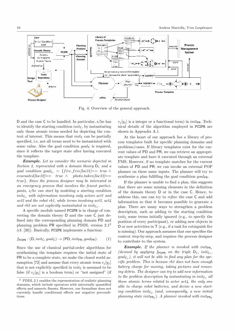
Fig. 4: Overview of the general approach.
D and the case C to be handled. In particular, s/he has
to identify the starting condition initC, by instantiating
only those atomic terms needed for depicting the con-
text of interest. This means that initC can be partially
specified, i.e, not all terms need to be instantiated with
some value. Also the goal condition goalC is required,
since it reflects the target state after having executed
the template.
Example. Let us consider the scenario depicted in
Section 2, represented with a domain theory D1 and a
goal condition goalC1 = fire free[loc31]== true ∧evacuated[loc32]== true ∧ photo taken[loc33]==
true. Since the process designer may be interested in
an emergency process that involves the fewest partici-
pants, s/he can start by modeling a starting condition
initC1with information involving only actors act1 and
act2 and the robot rb1, while terms involving act3, act4
and rb2 are not explicitly instantiated in initC1 .
A specific module named PC2PR is in charge of con-
verting the domain theory D and the case C just de-
fined into the corresponding planning domain PD and
planning problem PR specified in PDDL version 2.12
(cf. [26]). Basically, PC2PR implements a function:
fPC2PR : (D, initC, goalC)→ (PD, initPR, goalPR). (1)
Since the use of classical partial-order algorithms for
synthesizing the template requires the initial state of
PR to be a complete state, we make the closed world as-
sumption [72] and assume that every atomic term vj [yj ]
that is not explicitly specified in initC is assumed to be
false (if vj [yj ] is a boolean term) or “not assigned” (if
2 PDDL 2.1 enables the representation of realistic planningdomains, which include operators with universally quantifiedeffects and numeric fluents. However, our formalism does notcurrently handle conditional effects nor negative precondi-tions.
vj [yj ] is a integer or a functional term) in initPR. Tech-
nical details of the algorithm employed in PC2PR are
shown in Appendix A.1.
At the heart of our approach lies a library of pro-
cess templates built for specific planning domains and
problems/cases. If library templates exist for the cur-
rent values of PD and PR, we can retrieve an appropri-
ate template and have it executed through an external
PMS. However, if no template matches for the current
values of PD and PR, we can invoke an external POP
planner on these same inputs. The planner will try to
synthesize a plan fulfilling the goal condition goalPR.
If the planner is unable to find a plan, this suggests
that there are some missing elements in the definition
of the domain theory D or in the case C. Hence, to
address this, one can try to refine the case C and addinformation so that it becomes possible to generate a
plan. There are many ways to strengthen a problem
description, such as adding to the starting condition
initC some terms initially ignored (e.g., to specify the
position of every participant), or adding new objects in
D or new activities in T (e.g., if a task for extinguish fire
is missing). Our approach assumes that one specifies the
context step-by-step, and requires the process designer
to contribute to the system.
Example. If the planner is invoked with initPR1
(devised by applying fPC2PR on the triple D1, initC1,
goalC1), it will not be able to find any plan for the spe-
cific problem. This is because rb1 does not have enough
battery charge for moving, taking pictures and remov-
ing debris. The designer can try to add new information
to the problem description by instantiating in initC1 all
those atomic terms related to actor act4, the only one
able to charge robot batteries, and devise a new start-
ing condition initC2 (and, consequently, a new initial
planning state initPR2). A planner invoked with initPR2
A Planning Approach to the Automated Synthesis of Template-Based Process Models 11
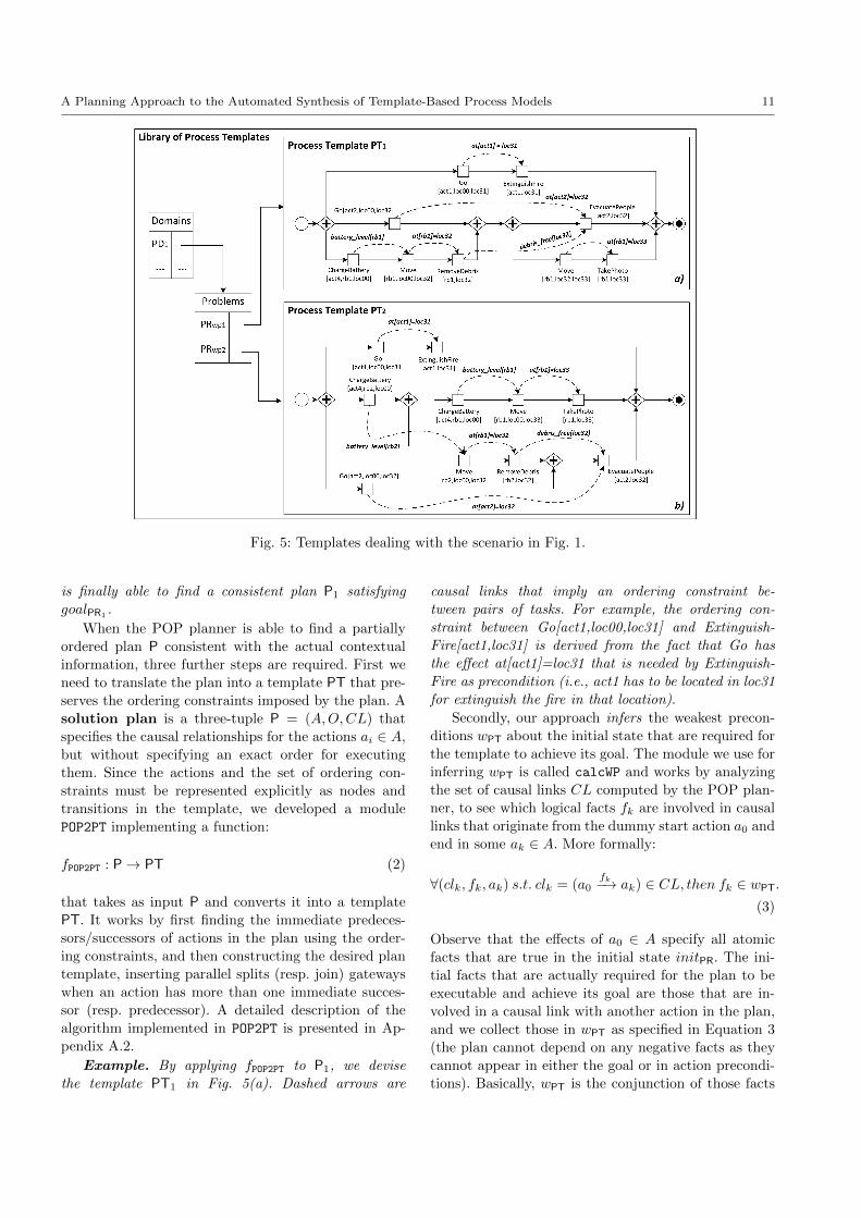
Fig. 5: Templates dealing with the scenario in Fig. 1.
is finally able to find a consistent plan P1 satisfying
goalPR1.
When the POP planner is able to find a partially
ordered plan P consistent with the actual contextual
information, three further steps are required. First we
need to translate the plan into a template PT that pre-
serves the ordering constraints imposed by the plan. A
solution plan is a three-tuple P = (A,O,CL) that
specifies the causal relationships for the actions ai ∈ A,
but without specifying an exact order for executing
them. Since the actions and the set of ordering con-
straints must be represented explicitly as nodes and
transitions in the template, we developed a module
POP2PT implementing a function:
fPOP2PT : P→ PT (2)
that takes as input P and converts it into a template
PT. It works by first finding the immediate predeces-
sors/successors of actions in the plan using the order-
ing constraints, and then constructing the desired plan
template, inserting parallel splits (resp. join) gateways
when an action has more than one immediate succes-
sor (resp. predecessor). A detailed description of the
algorithm implemented in POP2PT is presented in Ap-
pendix A.2.
Example. By applying fPOP2PT to P1, we devise
the template PT1 in Fig. 5(a). Dashed arrows are
causal links that imply an ordering constraint be-
tween pairs of tasks. For example, the ordering con-
straint between Go[act1,loc00,loc31] and Extinguish-
Fire[act1,loc31] is derived from the fact that Go has
the effect at[act1]=loc31 that is needed by Extinguish-
Fire as precondition (i.e., act1 has to be located in loc31
for extinguish the fire in that location).
Secondly, our approach infers the weakest precon-
ditions wPT about the initial state that are required for
the template to achieve its goal. The module we use for
inferring wPT is called calcWP and works by analyzing
the set of causal links CL computed by the POP plan-
ner, to see which logical facts fk are involved in causal
links that originate from the dummy start action a0 and
end in some ak ∈ A. More formally:
∀(clk, fk, ak) s.t. clk = (a0fk−→ ak) ∈ CL, then fk ∈ wPT.
(3)
Observe that the effects of a0 ∈ A specify all atomic
facts that are true in the initial state initPR. The ini-
tial facts that are actually required for the plan to be
executable and achieve its goal are those that are in-
volved in a causal link with another action in the plan,
and we collect those in wPT as specified in Equation 3
(the plan cannot depend on any negative facts as they
cannot appear in either the goal or in action precondi-
tions). Basically, wPT is the conjunction of those facts
12 Andrea Marrella, Yves Lesperance
strictly required for executing the plan P (and, conse-
quently, the devised template PT), and is used for de-
vising a new problem PRwp = wPT, goalPRwp. We can
then drop the closed world assumption. For any initial
state that satisfies wPT, the obtained process template
PT will be executable and achieve the goal condition
goalPR.
Example. If we invoke calcWP on the causal links
devised from P1 (cf. the dashed arrows of template
PT1 in Fig. 5(a)), we may infer wPT1. They in-
dicate that, for executing template PT1, it is required
to know the capabilities and the positions of act1,
act2, act4 and rb1 (cf. the logical facts on top of the
causal links, e.g., at[act1] = loc31, at[act2] = loc32,
etc.), the information about the battery level of rb1 (cf.
batteryLevel[rb1]) and the status of the location loc31
(cf. debris free[loc32]). No other contextual informa-
tion is required for a correct execution of the template;
for example, any additional information about further
actors and robots (their positions, battery level, etc.)
can be neglected for the enactment of PT1.
Thirdly, after the process template PT has been syn-
thesized starting from P, it can be stored in our library
together with information about the planning domain
PD and abstracted problem PRwp. Specifically, for every
different planning domain PD devised through our ap-
proach, there is a pointer to a list of different abstracted
planning problems PRwp used for obtaining consistent
plans in previous executions of our tool, together with
the devised process templates.
When a process designer defines a new domain
theory Dnew and a case Cnew, the software module
QueryLIB checks if the corresponding planning domainPDnew and problem PRnew (obtained by applying fPC2PRto Dnew and Cnew) are already present in our library.
If the library contains a planning domain PDlib and an
abstracted planning problem PRwp (together with the
associated template PTlib) such that PDlib ⊆ PDnew
and goalPRwp` goalPRnew
and with initPRnew` wPT,
then PTlib is executable with respect to PRnew (and
therefore with respect to Cnew).
Since a library template PTlib reflects an instanti-
ation of a flexible process in a specific case (i.e., it is
a single process instance ready to be enacted), there
is the risk that other library templates defined on the
same planning domain PDlib ⊆ PDnew and solving sim-
ilar problems to PRnew are not considered for the se-
lection. To tackle this issue, the QueryLIB module al-
lows the process designer to “generalize” the search by
setting some abstraction rules on specific data types
defined in the domain theory. For example, if the pro-
cess designer flags the data type Participant as “ab-
stracted”, the searching of an existing library template
that satisfies PDnew and PRnew is performed in two
steps. First, from each library template PTlib indexed
with PDlib ⊆ PDnew, the QueryLIB module substitutes
all the constants values representing the specific partic-
ipants involved in task instances with as many variables
(of type Participant) as the participants are. The same
substitution is done for the participants included in the
abstracted planning problem PRwp associated to PTlib.
Then, during the search, the QueryLIB module applies
a simple substitution mechanism of type variable/data
object [73] for verifying if there exists a valid binding
between the constant values representing the available
participants in initPRnewand the generic variables of
type Participant in PTlib. A valid binding is associated
to a variable/data object binding list that applies to
the abstracted planning problem PRwp and satisfies the
preconditions of task occurrences in PTlib.
Example. Let us consider the template PT1 in
Fig. 5(a), obtained with PD1 and PR2. Let us suppose
now that the designer, on the same planning domain
PD1, has devised a new planning problem PR2b (de-
rived from a new case C2b), with information about
actor act3 rather than about actor act2. At a first
glance, PT1 does not match with the information con-
tained in initPR2b, since PT1 requires the presence of
actor act2 for executing the template. However, if the
process designer decides to generalize the search task
with respect to the data type Participant, every con-
stant value of type Participant in PT1 is substituted
with a generic variable of type Participant. For ex-
ample, the tasks Go[act2,loc00,loc32] and Evacuate-
People[act2,loc32] become Go[x,loc00,loc32] and Evac-
uatePeople[x,loc32], and the information that con-
cern act2 in PRwp are affected as well (e.g., pro-
vides[act2, hatchet] becomes provides[x,hatchet]). The
QueryLIB module starts searching for a valid bind-
ing. The partial binding ..,x/act1,.. is not valid,
since the term provides[act1,hatchet] is false in initPR2b.
A valid partial binding is instead ..,x/act3,.., since
the term provides[act3,hatchet] is true in initPR2b
and the tasks Go[act3,loc00,loc32] and EvacuatePeo-
ple[act3,loc32] are executable in PT1 (i.e., they satisfy
the template’s tasks preconditions).
Despite the fact that a process template is exe-
cutable “as is” in a specific contextual situation, when
QueryLIB searches for an existing template in the li-
brary (i.e., for a valid binding with the current val-
ues of PDnew and PRnew), we can apply some abstrac-
tion rules that allow a library template to be used for
generating several models matching the properties of
different situations. This makes our templates reusable
in a variety of different contexts, in which we don’t
have complete information about the initial state. At
A Planning Approach to the Automated Synthesis of Template-Based Process Models 13
this point, the process designer may decide to execute
through an external PMS the template PTlib just found,
or to refine Dnew and Cnew if PTlib does not fit with the
designer expectations.
Example. Let us suppose that the template shown
in Fig. 5(a) does not satisfy at all the process designer,
since s/he could add one further robot rb2 to the sce-
nario in order to increase the degree of parallelism
in the tasks execution. It follows that a new starting
condition initC3 including also contextual information
about rb2 can be defined. The associated initial planning
state initPR3, together with the original goal condition
goalPR1 and the planning domain PD1 are first used for
verifying if a matching synthesized template is already
stored in the library. The library returns the template
PT1 shown in Fig. 5(a), since its weakest preconditions
wPT1 are satisfied by initPR3 (i.e., initPR3 ` wPT1), and
goal condition and planning domain are the same as be-
fore. Even if the template in Fig. 5(a) is executable with
initPR3 , the designer may try to obtain another plan
that would exploit the presence of the new robot rb2.
This can be done by directly invoking the planner with
the new information about the initial state. The plan-
ner can generate a new plan starting from initPR3 , and
the associated template PT2 is shown in Fig. 5(b). PT2
requires the presence of one more robot (i.e., robot rb2)
and more contextual information for being executed (so
its weakest preconditions wPT2are stronger than wPT1
),
but it provides a higher degree of concurrency in the ex-
ecution of its tasks. Notice also that the initial state
associated to PT1 is satisfied by the weakest precondi-
tions wPT2. This means that PT1 is executable in wPT2
,
and that the process designer can choose which tem-
plate is best for her/his purposes: one with less con-
currency in the tasks enactment but with the fewest
participants (cf., Fig. 5(a)), or one with more concur-
rency but requiring more resources for being executed
(cf., Fig. 5(b)).
If several matching templates (for which the weak-
est preconditions hold and which reach the desired goal
state) are retrieved from the library, the QueryLIB com-
ponent categorizes them on the basis of some parame-
ters useful for evaluating their quality. Specifically, each
template is stored with information about (i) the num-
ber of different participants involved; (ii) the number of
tasks in the control flow; (iii) the degree of parallelism
provided (i.e., the maximum number of tasks that can
be possibly executed concurrently at the same time)
and (iv) the weakest preconditions wPT associated to
the template, that help to understand the amount of
knowledge about the initial state that is required for
executing the template itself. At this point, the pro-
cess designer can choose which template provides the
required quality on the basis of the current case to be
dealt with. We do not currently discuss any mechanism
to evaluate and quantify the similarity between differ-
ent templates, but it is interesting to notice that the
presence of annotated tasks and causal links describing
the structure of a template allows potentially to con-
vert a template in a business process graph [21] and to
perform all the similarity metrics as described in [22]
(i.e., node matching similarity, structural similarity and
behavioral similarity).
5.2 Properties
A process template PT guarantees some interesting
properties, such as the executability of the template
with respect to the information available in the initial
state, and the property of sound concurrency, meaning
that concurrent activities of a template are proven to
be independent from each other.
Theorem 1 Given a solution plan P, a process tem-
plate PT synthesized for P using our approach is exe-cutable for any process case C that satisfies the weakest
preconditions wpPT inferred from P.
The proof is straightforward. By definition, a sound
planner generates a consistent plan [81] that leads from
an initial state to a goal. Since we represent the domain
theory/case as a PDDL planning domain/problem, the
planner synthesizes a plan (i.e., a process template) that
is executable with respect to Definition 7.
A second property we can prove is sound concur-
rency. Even if in a process designed by following data
and workflow patterns [23] the concurrent execution oftwo or more tasks should guarantee the consistency of
data accessed by the concurrent tasks, in practice this is
often not true. In fact, in complex environments there is
not a clear correlation between a change in the context
and corresponding process changes, making it difficult
to design by hand a process where concurrent tasks are
also independent. On the contrary, all concurrent tasks
of a template built with our approach are proven to be
independent from one another.
Theorem 2 Given a process template PT synthesized
with our approach, all concurrent tasks are indepen-dent.
Proof By contradiction, let us suppose that a process
template PT has two concurrent tasks t1 and t2 such
that t1 ∦ t2. Hence, t1 (or t2) has some effect affecting
the precondition of t2 (or of t1). This means that t1 . t2or t2 . t1. Since PT has been synthesized as result of a
POP planner, this dependency between t1 and t2 would
14 Andrea Marrella, Yves Lesperance
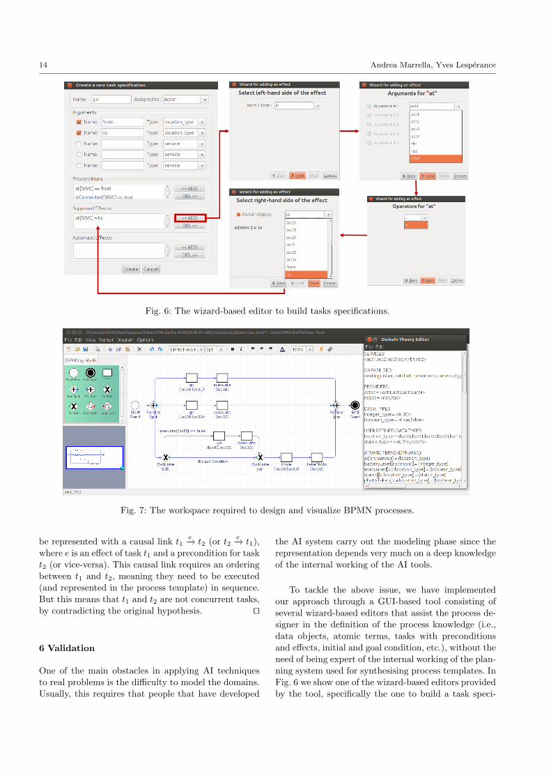
Fig. 6: The wizard-based editor to build tasks specifications.
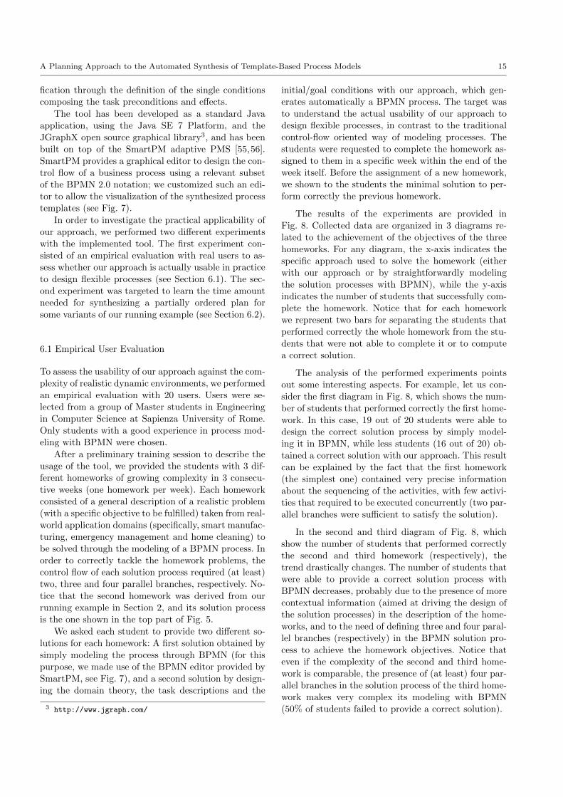
Fig. 7: The workspace required to design and visualize BPMN processes.
be represented with a causal link t1e−→ t2 (or t2
e−→ t1),
where e is an effect of task t1 and a precondition for task
t2 (or vice-versa). This causal link requires an ordering
between t1 and t2, meaning they need to be executed
(and represented in the process template) in sequence.
But this means that t1 and t2 are not concurrent tasks,
by contradicting the original hypothesis. ut
6 Validation
One of the main obstacles in applying AI techniques
to real problems is the difficulty to model the domains.
Usually, this requires that people that have developed
the AI system carry out the modeling phase since the
representation depends very much on a deep knowledge
of the internal working of the AI tools.
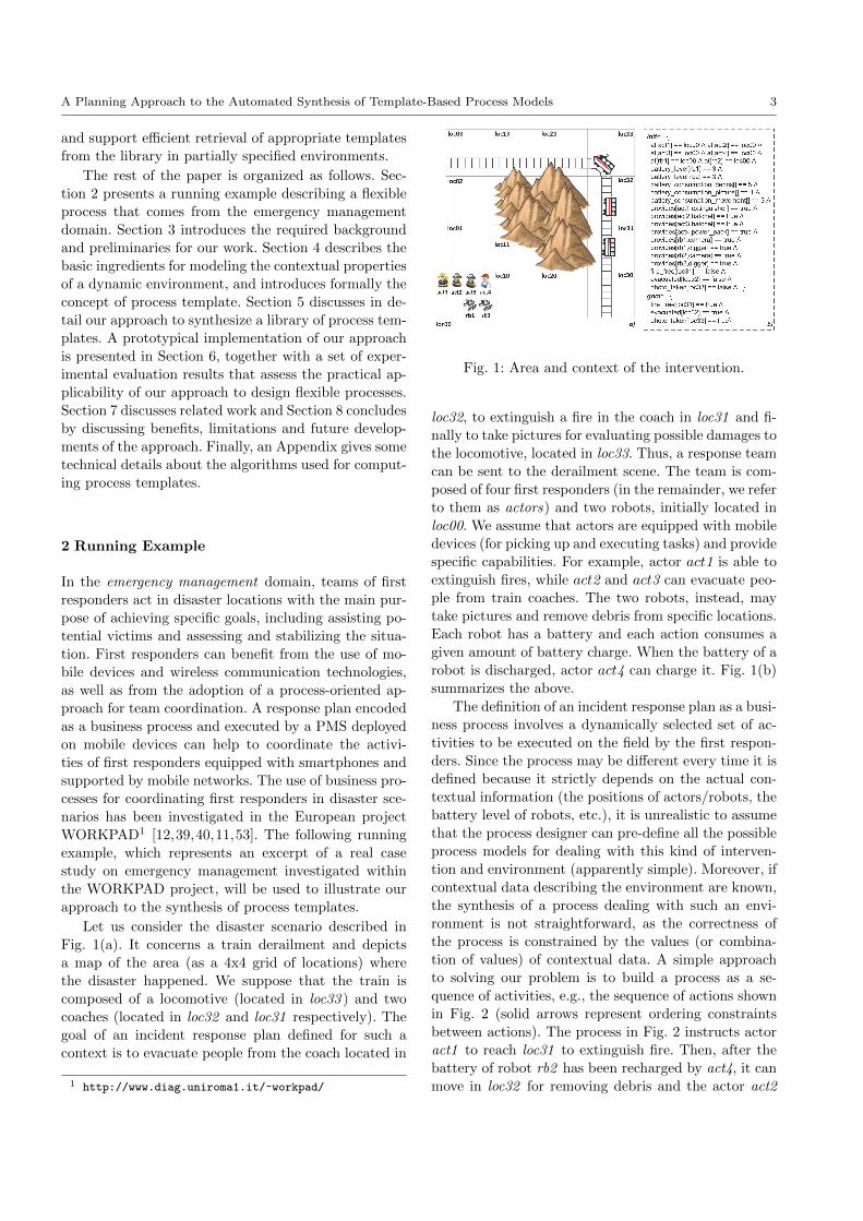
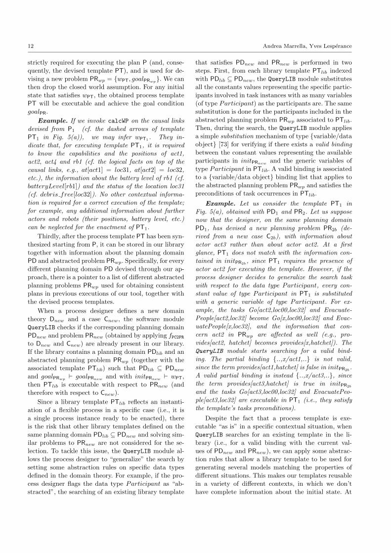
To tackle the above issue, we have implemented
our approach through a GUI-based tool consisting of
several wizard-based editors that assist the process de-
signer in the definition of the process knowledge (i.e.,
data objects, atomic terms, tasks with preconditions
and effects, initial and goal condition, etc.), without the
need of being expert of the internal working of the plan-
ning system used for synthesising process templates. In
Fig. 6 we show one of the wizard-based editors provided
by the tool, specifically the one to build a task speci-
A Planning Approach to the Automated Synthesis of Template-Based Process Models 15
fication through the definition of the single conditions
composing the task preconditions and effects.
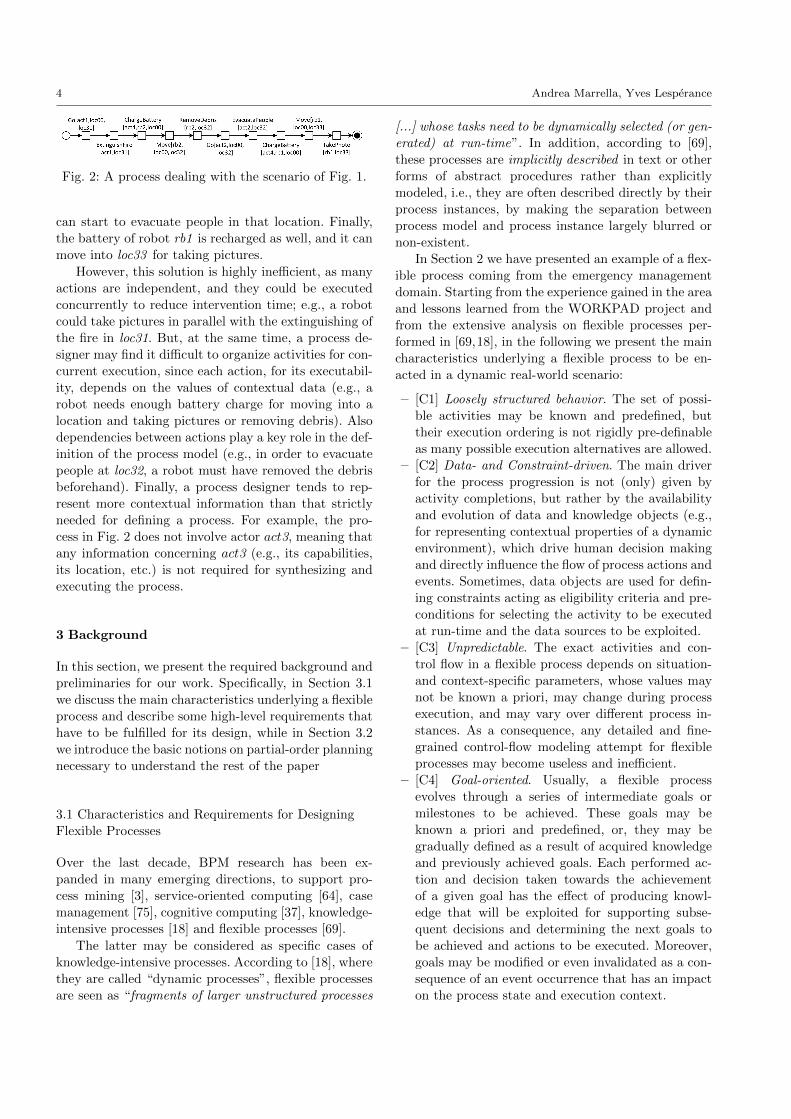
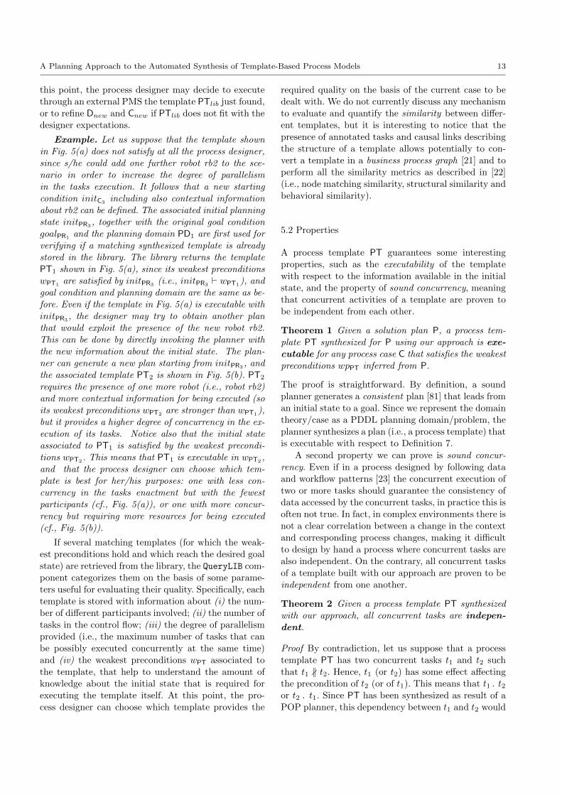
The tool has been developed as a standard Java
application, using the Java SE 7 Platform, and the
JGraphX open source graphical library3, and has been
built on top of the SmartPM adaptive PMS [55,56].
SmartPM provides a graphical editor to design the con-
trol flow of a business process using a relevant subset
of the BPMN 2.0 notation; we customized such an edi-
tor to allow the visualization of the synthesized process
templates (see Fig. 7).
In order to investigate the practical applicability of
our approach, we performed two different experiments
with the implemented tool. The first experiment con-
sisted of an empirical evaluation with real users to as-
sess whether our approach is actually usable in practice
to design flexible processes (see Section 6.1). The sec-
ond experiment was targeted to learn the time amount
needed for synthesizing a partially ordered plan for
some variants of our running example (see Section 6.2).
6.1 Empirical User Evaluation
To assess the usability of our approach against the com-
plexity of realistic dynamic environments, we performed
an empirical evaluation with 20 users. Users were se-
lected from a group of Master students in Engineering
in Computer Science at Sapienza University of Rome.
Only students with a good experience in process mod-
eling with BPMN were chosen.
After a preliminary training session to describe the
usage of the tool, we provided the students with 3 dif-
ferent homeworks of growing complexity in 3 consecu-tive weeks (one homework per week). Each homework
consisted of a general description of a realistic problem
(with a specific objective to be fulfilled) taken from real-
world application domains (specifically, smart manufac-
turing, emergency management and home cleaning) to
be solved through the modeling of a BPMN process. In
order to correctly tackle the homework problems, the
control flow of each solution process required (at least)
two, three and four parallel branches, respectively. No-
tice that the second homework was derived from our
running example in Section 2, and its solution process
is the one shown in the top part of Fig. 5.
We asked each student to provide two different so-
lutions for each homework: A first solution obtained by
simply modeling the process through BPMN (for this
purpose, we made use of the BPMN editor provided by
SmartPM, see Fig. 7), and a second solution by design-
ing the domain theory, the task descriptions and the
3 http://www.jgraph.com/
initial/goal conditions with our approach, which gen-
erates automatically a BPMN process. The target was
to understand the actual usability of our approach to
design flexible processes, in contrast to the traditional
control-flow oriented way of modeling processes. The
students were requested to complete the homework as-
signed to them in a specific week within the end of the
week itself. Before the assignment of a new homework,
we shown to the students the minimal solution to per-
form correctly the previous homework.
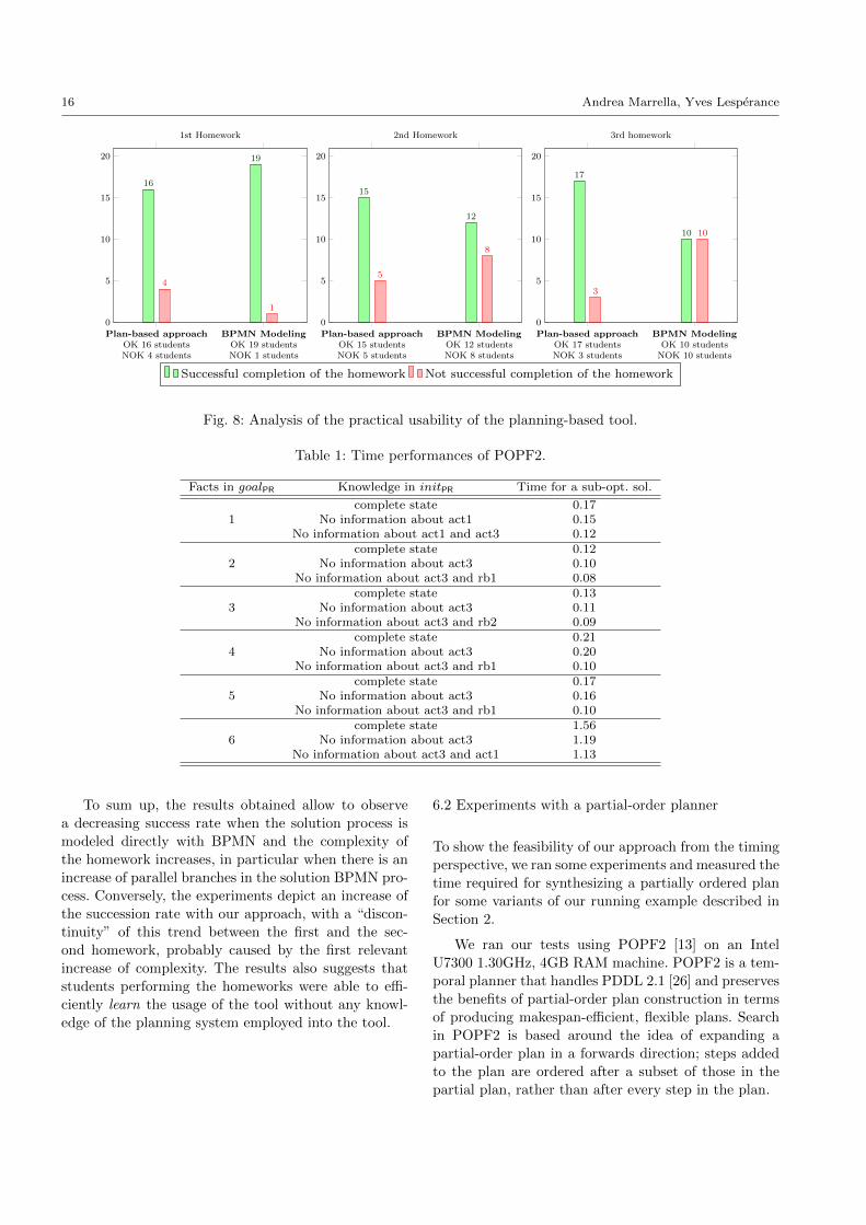
The results of the experiments are provided in
Fig. 8. Collected data are organized in 3 diagrams re-
lated to the achievement of the objectives of the three
homeworks. For any diagram, the x-axis indicates the
specific approach used to solve the homework (either
with our approach or by straightforwardly modeling
the solution processes with BPMN), while the y-axis
indicates the number of students that successfully com-
plete the homework. Notice that for each homework
we represent two bars for separating the students that
performed correctly the whole homework from the stu-
dents that were not able to complete it or to compute
a correct solution.
The analysis of the performed experiments points
out some interesting aspects. For example, let us con-
sider the first diagram in Fig. 8, which shows the num-
ber of students that performed correctly the first home-
work. In this case, 19 out of 20 students were able to
design the correct solution process by simply model-
ing it in BPMN, while less students (16 out of 20) ob-
tained a correct solution with our approach. This result
can be explained by the fact that the first homework
(the simplest one) contained very precise information
about the sequencing of the activities, with few activi-
ties that required to be executed concurrently (two par-
allel branches were sufficient to satisfy the solution).
In the second and third diagram of Fig. 8, which
show the number of students that performed correctly
the second and third homework (respectively), the
trend drastically changes. The number of students that
were able to provide a correct solution process with
BPMN decreases, probably due to the presence of more
contextual information (aimed at driving the design of
the solution processes) in the description of the home-
works, and to the need of defining three and four paral-
lel branches (respectively) in the BPMN solution pro-
cess to achieve the homework objectives. Notice that
even if the complexity of the second and third home-
work is comparable, the presence of (at least) four par-
allel branches in the solution process of the third home-
work makes very complex its modeling with BPMN
(50% of students failed to provide a correct solution).
16 Andrea Marrella, Yves Lesperance
Plan-based approachOK 16 studentsNOK 4 students
BPMN ModelingOK 19 studentsNOK 1 students
0
5
10
15
20
16
19
4
1
1st Homework
Plan-based approachOK 15 studentsNOK 5 students
BPMN ModelingOK 12 studentsNOK 8 students
0
5
10
15
20
15
12
5
8
2nd Homework
Plan-based approachOK 17 studentsNOK 3 students
BPMN ModelingOK 10 students
NOK 10 students
0
5
10
15
20
17
10
3
10
3rd homework
Successful completion of the homework Not successful completion of the homework
Fig. 8: Analysis of the practical usability of the planning-based tool.
Table 1: Time performances of POPF2.
Facts in goalPR Knowledge in initPR Time for a sub-opt. sol.
1complete state 0.17
No information about act1 0.15No information about act1 and act3 0.12
2complete state 0.12
No information about act3 0.10No information about act3 and rb1 0.08
3complete state 0.13
No information about act3 0.11No information about act3 and rb2 0.09
4complete state 0.21
No information about act3 0.20No information about act3 and rb1 0.10
5complete state 0.17
No information about act3 0.16No information about act3 and rb1 0.10
6complete state 1.56
No information about act3 1.19No information about act3 and act1 1.13
To sum up, the results obtained allow to observe
a decreasing success rate when the solution process is
modeled directly with BPMN and the complexity of
the homework increases, in particular when there is an
increase of parallel branches in the solution BPMN pro-
cess. Conversely, the experiments depict an increase of
the succession rate with our approach, with a “discon-
tinuity” of this trend between the first and the sec-
ond homework, probably caused by the first relevant
increase of complexity. The results also suggests that
students performing the homeworks were able to effi-
ciently learn the usage of the tool without any knowl-
edge of the planning system employed into the tool.
6.2 Experiments with a partial-order planner
To show the feasibility of our approach from the timing
perspective, we ran some experiments and measured the
time required for synthesizing a partially ordered plan
for some variants of our running example described in
Section 2.
We ran our tests using POPF2 [13] on an Intel
U7300 1.30GHz, 4GB RAM machine. POPF2 is a tem-
poral planner that handles PDDL 2.1 [26] and preserves
the benefits of partial-order plan construction in terms
of producing makespan-efficient, flexible plans. Search
in POPF2 is based around the idea of expanding a
partial-order plan in a forwards direction; steps added
to the plan are ordered after a subset of those in the
partial plan, rather than after every step in the plan.
A Planning Approach to the Automated Synthesis of Template-Based Process Models 17
The experimental setup was run on variants of our
running example. We represented 7 planning actions
in PD (corresponding to 7 different tasks stored in the
tasks repository T), annotated with 7 relational predi-
cates and 6 numeric fluents, in order to make the plan-
ner search space sufficiently challenging. Then, we de-
fined 18 different planning problems of varying com-
plexity by manipulating the number of facts in the goal.
As well, we examined how irrelevant domain knowledge
affects the performance of the planner. Starting from a
planning problem PR with an initial state initPR com-
pletely specified and with a goal condition goalPR ex-
pressed as the conjunction of n facts, we manipulated
the specification of the initial state initPR to reduce the
number of known facts. In our experiments, the number
of facts in goal condition ranges from 1 single fact to
a conjunction of 6 logical facts (that make the contex-
tual problem harder). As shown in Table 1, for a given
goal condition composed of n facts, our purpose was
to measure the computation time needed for finding a
sub-optimal solution for problems specified with initial
states with a decreasing amount of knowledge. The col-
umn labeled as “Knowledge in initPR” makes explicit
which information is removed from the initial state of
the planning problem. For example, if we consider our
running scenario, whose goal condition is composed of
3 facts and characterized by a complete specification of
the initial state, the time needed for finding a solution
plan is of 0.13 seconds. After removing from the ini-
tial state all the information concerning the actor act3,
the time required for computing the plan decreases to
0.11 seconds. In general, for a given goal condition, re-
moving “irrelevant information” from the initial state
reduces the possibilities to select “wrong” planning ac-
tions (e.g., any action that involves act3) during the
plan synthesis and, consequently, reduces the search
space and the computation required for synthesizing
the plan.
Concerning the fact that variant times observed in
Table 1 are quite small, this depends by the specific
case study tested, which is of medium size. With larger
domain theories, since automated planning is known
to be PSPACE-complete (cf. [27]), the variants would
have been certainly larger. This emphasizes once more
the importance of exploiting the weakest preconditions
in the definition of the initial state to considerably limit
the exploration of the search space.
We finally notice that a sub-optimal solution may
include more actions than those strictly required for
fulfilling the goal, and when the number of facts in
a goal condition increases, the quality of the solution
may decrease. This happens beacuse the current ver-
sion of POPF2 (which is currently the best performing
POP planner available in the literature) is able to build
partial-order plans for which only the correctness of the
solution is guaranteed (nothing can be really said on its
optimality in terms of plan’s length). However, the fact
that our approach is able to generate standard PDDL
files would allow us to integrate different planners for
the generation of the templates. Obviously using plan-
ning we can also look for optimal plans, though this
would be more costly. Nonetheless, based on the re-
sults of our experiments, we can conclude that POPF2
is feasible for the generation of medium-sized flexible
process templates as used in practice.
7 Related Work
Process modeling is the first and most important step
in the BPM lifecycle [50], which intends to provide a
high-level specification of a business process that is in-
dependent from implementation and serves as a ba-
sis for process automation and verification. Traditional
business process models are usually well-structured, i.e,
they reflect highly repeatable and predictable routine
work with low flexibility requirements [49]. All possi-
ble options and decisions that can be made during pro-
cess enactment are statically pre-defined at design-time.
A major assumption is that such processes, after hav-
ing been modeled, can be repeatedly instantiated and
executed in a predictable and controlled manner. The
current leading commercial PMS products [14,77,41,
60,83] and research prototypes [46,35] support the full
business processes life-cycle by providing tools used to
model, configure and enact business processes.
However, current BPM technology is generally
based on rigid process models making its applica-
tion difficult in highly dynamic and possibly evolving
domains [69], where pre-specifying the entire process
model is not possible. This problem can be mitigated
through specific approaches to process variability, which
allow to customize a process by implementing specific
variants of the process in a way that a model of each
variant can be derived by adding or deleting fragments
according to a domain model or to some customization
option [44,5]. Customization of process models can be
made either at design-time or run-time.
Approaches that support customization decisions
made at run-time are not concerned with maintaining
a library of process models (and their variants) to be
reused at run-time. On the contrary, such approaches
rely on a unitary process model from which individual
process instances may deviate at run-time on a case-
by-case basis. Run-time customization has been studied
as a separate topic in the literature, and is known as
process adaptation. This is the case of two well-known
18 Andrea Marrella, Yves Lesperance
adaptive PMSs, like ADEPT2 [29] and SmartPM [55,
56], which support the run-time adaptation of the
process instances by dynamically adding/implementing
process fragments that were not specified in the original
process model. In our work, as stated in Section 3.1 we
made the choice to focus on design-time aspects of flex-
ible processes. Nonetheless, we think that our approach
can be complementary to process adaptation. In fact,
the process templates that are automatically generated
by our approach can be seen as candidate process models
to be enacted with the existing adaptive PMSs.
On the other hand, process models can be cus-
tomized at design-time in order to capture families of
process variants derived via transformations of the cus-
tomizable process model of interest, e.g., by removal
of behaviour from the underlying process model (vari-
ability by restriction) or by addition of dedicated pro-
cess variants (variability by extension). There exist four
different ways to approach the customization of a pro-
cess model: (i) by defining specific configurable nodes
within the process that capture variability through dif-
ferent customization options [71,45]; (ii) by annotating
process model elements (control-flow nodes, resources,
objects, etc.) with properties of the application do-
main [70]; in this way, all the model elements whose do-
main conditions are evaluated to false will be removed
from the model; (iii) by specializing process model el-
ements with specific variation points that provide sev-
eral possible refinements to the process [31]; (iv) by
applying specific change operations (e.g., insert, delete,
move, replace, etc.) to restrict or extend the process
model [32].
The fact is that the existing approaches to design-
time process variability do not consider that flexi-
ble processes are incomplete “by nature”. Basically,
such approaches require to manually pre-define a “base
model” explicitly marked with several “adjustment
points” identified in one of the ways listed above. While
this activity works perfectly in case of traditional busi-
ness processes, it can be time-consuming and error-
prone when flexible processes are to be modeled, due
to their context-dependent nature that make difficult
the specification of all the potential tasks interactions
and process variants in advance.
Conversely, in our planning-based approach the pro-
cess designer is not required to define in advance neither
a base process model nor its individual variants. The de-
signer specifies just the contextual knowledge (as a do-
main theory) in which the flexible process is embedded,
a repository of tasks and some logical constraints ex-
pressed in terms of task preconditions and effects, which
allow to make explicit the connection between tasks and
contextual data. This information is then used to feed
a POP planner that will automatically build a process
template. At this point, by modifying the domain the-
ory or by inserting/removing new/existing tasks in the
repository, it is possible to obtain several process tem-
plates that can be considered as different process vari-
ants to achieve a goal condition. If compared with the
traditional approaches to process variability, the novelty
here is that such templates are synthesised automati-
cally on a case-by-case basis, without the need of defin-
ing them manually; this feature makes our approach
specifically tailored to the modeling of flexible processes.
As discussed in Section 3.1, flexible processes usu-
ally exhibit a loosely structured behavior and require
process tasks to be semantically annotated with pre-
conditions and effects defined over contextual data.
While most approaches in the Semantic Business Pro-
cess Management field (SBPM) mainly concentrate on
the annotation of process models (cf. [76,10]), with-
out any automatic generation of the models, in this pa-
per we focus on automatically synthesizing process tem-
plates by means of their semantic annotations.
To this end, we focused on declarative approaches
to business process management, as they offer a way of
modeling processes that integrates a certain amount of
flexibility into the process models [66]. The idea under-
lying declarative approaches consists of performing the
modeling phase of processes by exploiting the concept of
control-flow constraints for the specification of relation-
ships among tasks, instead of strictly and rigidly defin-
ing the control-flow of process tasks using a procedural
language. Recently, several declarative approaches for
supporting loosely-structured processes have been pro-
posed [65,80,30]. DECLARE [65] is a constraint-based
PMS that uses a declarative language grounded in lin-
ear temporal logic (LTL [79]) for the development and
execution of process models. Rather than using a proce-
dural language for expressing the allowed sequences of
tasks, it describes processes through the usage of con-
straints: the idea is that every task sequence can be
performed, except when it does not respect them. Sim-
ilarly, Alaska [80], a tool suite developed at the Uni-
versity of Innsbruck, allows to define task constraints
that implicitly define possible execution alternatives by
prohibiting undesired execution behavior. Finally, the
work [30] presents a declarative approach that enables
the modeling of dynamic sets of candidate activities
from which a subset is automatically selected for exe-
cution. While the above approaches allow to define con-
straints exclusively on process activities (i.e., the data
perspective, which plays a relevant role for flexible pro-
cesses, is neglected in the definition of task constraints),
our approach allows a process designer to explicitly cap-
ture the contextual domain (i.e., the data perspective)
A Planning Approach to the Automated Synthesis of Template-Based Process Models 19
in which the process is meant to run, and to define con-
straints between tasks and data.
Processes may also be specified using the data-
centric paradigm. In data-centric methodologies, the
data perspective is predominant and captures domain-
relevant object types, their attributes, their possible
states and life-cycles, and their interrelations, which to-
gether form a complex data structure, i.e., an informa-
tion model. This information model enables the iden-
tification and definition of the activities that rely on
the object-related information and act on it, produc-
ing changes on attribute values, relations and object
states. Notice that activities of a data-centric process,
which do not have a pre-specified order, are triggered
only when the required data is available, i.e., the evolu-
tion of the information model drives the process execu-
tion. There exist several approaches belonging to the
data-centric paradigm: Case Handling [78], Artifact-
centric process models [36], Object-aware process mod-
els [43], Data-Centric Dynamic Systems [6] and the
OMG’s emerging Case Management Modeling Notation
standard (CMMN) [63]. All these approaches are po-
tentially good candidates to deal with the requirements
presented in Section 3.1. However, they require to man-
ually anticipate in an explicit way all the interrelations
between tasks and the information model (i.e., the con-
textual properties of the domain), and this could be a
complex activity to be performed at design-time. This is
particularly true in dynamic environments, where the
process designer often lacks the needed knowledge to
model every required constraint ahead of time.
On the contrary, the approach presented in this pa-
per allows to declare in an implicit way (by means of
tasks preconditions and effects) the constraints between
tasks and data. The novelty is that the control flow con-
straints between tasks (i.e., causal links and ordering
constraints) will be automatically and contextually gen-
erated by an external planner, together with the process
template to be executed.
A further research area related to our approach is
the one of service discovery. In the literature, there ex-
ists a wide range of solutions for the automated dis-
covery and selection of services specified via a service
profile and a process model [84]. A service profile de-
scribes the signature of a service in terms of its input
and output parameters, and its execution semantics via
preconditions and effects. Prominent approaches to rep-
resent such profiles are, for example, WSDL and SML.
A service process model describes the operational be-
havior of a service in terms of its internal control and
data flow. Such models are described, for example, in
OWL-S, WSML and USDL.
Most of service discovery techniques rely on the
matching of the semantic annotations of service profile
(i.e., signature matching) and/or process model. With-
out any doubt, task specifications in our approach and
service profiles are similar concepts. However, there ex-
ists a relevant difference in what our approach and ser-
vice discovery techniques aim to discover. While service
discovery approaches aim at locating and selecting ex-
isting services that are relevant for a given request, the
main target of our approach is to synthesize new non-
existing process templates. Therefore, we exploit the se-
mantic annotations of tasks (preconditions and effects)
included in a repository not for discovering tasks, but
for generating process templates that orchestrate such
tasks in order to achieve a goal condition.
Nonetheless, we think that service discovery tech-
niques can provide a great value in the phase of re-
trieving process templates from our existing library. As
discussed in Section 5, we currently provide a basic se-
mantic binding mechanism for the selection of a suit-
able template. As a future work, it is our intention to
consider service discovery techniques to improve the se-
lection mechanism of process templates.
7.1 Plan-based Process Design
The AI community has been involved with research on
process management for several decades, and AI tech-
nologies can play an important role in the construction
of PMS engines that manage complex processes, while
remaining robust, reactive, and adaptive in the face of
both environmental and tasking changes [61].
A number of research works exist on the use of plan-
ning techniques in the context of BPM, covering the
various stages of the process life cycle. For the run-
time phase, existing literature works reports on the use
of planners to allocate process activities to (human) re-
sources [15], whereas works [52,54,57,9,55,56] report
on approaches to adapt the running process instances
to cope with anomalous situations, including connec-
tion anomalies, exogenous events and task faults. The
work [8] discusses at high level how the use of an in-
telligent assistant based on planning techniques may
suggest compensation procedures or the re-execution
of activities if some anticipated failure arises during
the process execution. In [42] the authors describe how
planning can be interleaved with process execution and
plan refinement, and investigates plan patching and
plan repair as means to enhance flexibility and respon-
siveness. Similarly, the approach presented in [68] high-
lights the improvements that a legacy workflow applica-
tion can gain by incorporating planning techniques into
20 Andrea Marrella, Yves Lesperance
its day-to-day operation. In the context of process min-
ing, the works [20,17,16,48] use planning techniques to
recover and align events log traces against imperative
and declarative process models.
Readers should observe that the entire aforemen-
tioned approaches use planning techniques for com-
pletely different purposes. Some research works also ex-
ist that use planning techniques to deal with problems
for the design-time phase, and the closest to our ap-
proach are [74,67,25,34].
The work [74] presents the basic idea behind the
use of planning techniques for generating a process
schema, but no implementation seems to be provided,
and the direct use of the PDDL language for speci-
fying the domain theory requires a deep understand-
ing of AI planning technology. In [67], the authors
exploit the IPSS planner for modeling processes in
SHAMASH [4], a knowledge-based system that uses a
rule-based approach. To automate the process model
generation, they first translate the semantic represen-
tation of SHAMASH into the IPSS language. Then,
IPSS produces a parallel plan of activities that is fi-
nally translated back into SHAMASH and is presented
graphically to the user. This work proposes the schedul-
ing of parallel activities (that implicitly handle time and
resource constraints), meta-modeling that deals with
planning explicitly, and suggests that learning could be
used for process optimization. However, in [74] and
[67] the emphasis is on supporting processes for which
one has complete knowledge, while for flexible processes
some contextual information may not be available at
the time of process model synthesis. Conversely, our
approach allows the specification of process templates
in partially specified environments, i.e., such templates
require a fragment of the knowledge of the initial state
to successfully achieve their objectives. We identify the
weakest preconditions of process templates, and all the
states satisfying such preconditions are good candidates
for executing them.
The work [25] proposes a new life cycle for workflow
management based on the continuous interplay between
learning and planning. The approach is based on learn-
ing activities as planning operators and feeding them
to a planner that generates the process model. An in-
teresting result concerns the possibility of producing
process models even though the activities may not be
accurately described. In such cases, the authors use a
best-effort planner that is always able to create a plan,
even though the plan may be incorrect. By refining the
preconditions and effects of planning actions, the plan-
ner will be able to produce several candidate plans, and
after a finite number of refinements, the best candidate
plan (i.e., the one with the lowest number of unsatis-
fied preconditions) is translated into a process model.
Unfortunately, as acknowledged in [25], the best plan
found is often far from the correct solution. According
to Theorem 1, one of the strengths of our approach re-
lies on its ability to generate process templates that are
always executable for any case that satisfies the weakest
preconditions inferred from the template itself.
The SEMPA approach [34] introduces a semantic-
based automatic planning of process models. In
SEMPA, process actions are semantically described by
specifying their input/output parameters with respect
to an ontology implemented in OWL [7]. An action
state graph (ASG) is automatically derived from the
semantic information about input/output parameters.
It includes those process actions that lead to the given
goals from a pre-specified initial state. Then, a pro-
cess model represented as an UML activity diagram is
derived from the ASG by identifying the required con-
trol flow for the process. If compared with other plan-
ning approaches, the planning algorithm implemented
in SEMPA for the derivation of the ASG provides some
interesting characteristics, such as the ability to build
the ASG in presence of initial state uncertainty and
with different conflicting goals. The problem here is that
concurrent activities of the generated process are not
proven to be independent from each other with respect
to data. On the contrary, concurrent activities of a pro-
cess template generated by our approach are proven to
be effectively independent one from another (i.e., con-
current tasks cannot affect the same data)
8 Concluding Remarks
In the last years, there was a growing trend of man-
aging flexible processes in dynamic environments [69],
mainly due to the increased availability of sensors dis-
seminated in the world that allow to monitor the evo-
lution of several real-world objects of interest and to
support mobile workers that execute tasks in such dy-
namic settings. According to the recent keynote talk
performed by Rick Hull at BPM 2016 Conference [38],
the traditional BPM approaches are not tailored for the
management of flexible processes, and advances in goal
identification and planning are clearly needed, that is,
enabling process designers to take advantage of knowl-
edge that is relevant to a decision or task at hand, and
ignore knowledge that is irrelevant.
This paper goes exactly in the above direction and
addresses the problem of developing template-based
process models for processes and application contexts
which demand flexibility (e.g., processes for emergency
management). To this end, we developed a technique
A Planning Approach to the Automated Synthesis of Template-Based Process Models 21
based on Partial-Order Planning algorithms and declar-
ative specifications of process tasks for synthesizing a
library of process templates to be enacted in contex-
tual scenarios. The resulting templates guarantee sound
concurrency in the execution of their activities and are
reusable in a variety of partially specified contextual
environments. A key characteristic of our approach is
the role of contextual data acting as a driver for process
templates generation.
Since one of the main obstacles when dealing with a
flexible process lies in the difficulty of interacting with
and manipulating the knowledge embedded into the
process, we have implemented a dedicated user-friendly
graphical interface that helps the process designer in the
definition/refinement of the domain theory/case and in
the choice of the right template (i.e., one having the
required quality, if several templates satisfy the cur-
rent case) to be selected for the execution in a specific
contextual situation. To this end, we have performed a
complete validation of the approach by investigating its
practical applicability for designing flexible processes.
Even if our work is focused on process modeling at
design-time, we think that the proposed approach can
be complementary to run-time approaches to process
adaptation. In fact, the process templates that are au-
tomatically generated by our approach can be seen as
candidate process models to be enacted with the exist-
ing adaptive PMSs, which in general rely on a unitary
process model from which individual process instances
may deviate at run-time on a case-by-case basis. In par-
ticular, we are currently working on integrating our ap-
proach with SmartPM [55,56], an adaptive PMS that
accepts in input process models whose tasks specifica-
tion and domain theory formalization is similar to the
one proposed in our approach.
The fact that our approach relies on well-founded
planning formalisms opens the door to very promising
future works. First of all, since our approach is able to
automatically encode planning problems in the stan-
dard and system-independent PDDL language, one can
seamlessly update to the recent version of the best per-
forming (or expressive) POP planner, with evident ad-
vantages in term of versatility and customization. In
fact, the effort to integrate a different planner does
not go beyond installing the new planner and load-
ing the planning-problem formulation that is gener-
ated through our approach. The problem formulation
remains unchanged when moving from one planner to
the other. A second future direction for this work is
to generate and support hierarchical process templates,
with high-level templates achieving more general goals
that can invoke simpler templates to achieve some of
their subgoals. It seems that agent-technology can pro-
vide promising approaches and methods to address this
challenge. We also plan to address some expressiveness
limitations of our POP-based tool, such as express-
ing complex goal conditions (comprising, for example,
the use of existential quantifiers, disjunctions and inter-
mediate subgoals), handling preferences, representing
conditional effects and negative preconditions (they are
currently not supported by most POP planners, includ-
ing POPF2) and supporting non functional-properties
(like cost or time-constraints). A third interesting fu-
ture work is to devise a set of design-time guidelines
that may help the process designer in the selection of
the tasks to be included in the repository and in the
refinement of a process template. Finally, we are also
working on the formalization of new quantitative met-
rics for evaluating process templates’ quality.
This paper extends previous work in [51] in several
directions by includes many new elements that were
neglected in our previous work:
– a new section describing the characteristics of flexi-
ble processes and requirements for managing them.
If, on the one hand, such requirements motivate the
need of our work in the BPM context, on the other
hand they have provided concrete pointers to the
building of the tool underlying the proposed ap-
proach;
– a new section describing the tool’s implementation
and user interface;
– a more thorough description of how process tem-plates are concretely retrieved from the library, an
aspect that was neglected in our previous work;
– a completely new set of experiments to test the us-
ability of the approach against real users, in com-
parison with traditional activity-centric approaches
to BPM;
– the related work section has been partially rewritten
and extended significantly;
– the description of flexible processes is more detailed
and complete;
– all the details of the translation algorithms for in-
terfacing with the planner; i.e., for translating a
domain theory and a process case into a planning
domain and a planning problem, and for convert-
ing a partially ordered plan into a process template.
These algorithms, which are included in a dedicated
Appendix, allow our approach to be replicated and
concretely implemented by any researcher;
– all other sections of the paper have been edited and
refined to present the material more thoroughly.
22 Andrea Marrella, Yves Lesperance
References
1. van der Aalst, W., Pesic, M., Schonenberg, H.: Declara-tive Workflows: Balancing between Flexibility and Sup-port. Computer Science - Research and Development23(2), 99–115 (2009)
2. van der Aalst, W.M.: Business Process Management: AComprehensive Survey. ISRN Software Engineering 2013(2013). URL http://dx.doi.org/10.1155/2013/507984
3. van der Aalst, W.M.: Process mining: data science in ac-tion. Springer (2016)
4. Aler, R., Borrajo, D., Camacho, D.: A Knowledge-based Approach for Business Process Reengineering,SHAMASH. Know.-Based Syst. 15(8) (2002)
5. Ayora, C., Torres, V., Weber, B., Reichert, M.,Pelechano, V.: VIVACE: A framework for the systematicevaluation of variability support in process-aware infor-mation systems. Information and Software Technology57, 248–276 (2015). URL https://doi.org/10.1016/j.
infsof.2014.05.0096. Bagheri Hariri, B., Calvanese, D., de Giacomo, G.,
Deutsch, A., Montali, M.: Verification of Relational Data-centric Dynamic Systems with External Services. In:Proceedings of the 32nd Symposium on Principles ofDatabase Systems, PODS ’13, pp. 163–174. ACM, NewYork, NY, USA (2013). DOI 10.1145/2463664.2465221.URL http://doi.acm.org/10.1145/2463664.2465221
7. Bechhofer, S., Van Harmelen, F., Hendler, J., Horrocks,I., McGuinness, D.L., Patel-Schneider, P.F., Stein, L.A.,et al.: Owl web ontology language reference. W3C rec-ommendation 10, 2006–01 (2004)
8. Beckstein, C., Klausner, J.: A Meta Level Architecturefor Workflow Management. Journal of Integrated Designand Process Science 3(1), 15–26 (1999)
9. van Beest, N.R., Kaldeli, E., Bulanov, P., Wortmann,J.C., Lazovik, A.: Automated runtime repair of businessprocesses. Information Systems 39, 45–79 (2014). DOI10.1016/j.is.2013.07.003
10. Brockmans, S., Ehrig, M., Koschmider, A., Oberweis, A.,Studer, R.: Semantic alignment of business processes. In:ICEIS (3), pp. 191–196 (2006)
11. Catarci, T., de Leoni, M., Marrella, A., Mecella, M.,Russo, A., Steinmann, R., Bortenschlager, M.: Workpad:Process management and geo-collaboration help disasterresponse. IJISCRAM 3(1) (2011)
12. Catarci, T., de Leoni, M., Marrella, A., Mecella, M., Sal-vatore, B., Vetere, G., Dustdar, S., Juszczyk, L., Man-zoor, A., Truong, H.L.: Pervasive software environmentsfor supporting disaster responses. IEEE Internet Com-puting 12(1) (2008)
13. Coles, A.J., Coles, A., Fox, M., Long, D.: Forward-Chaining Partial-Order Planning. In: ICAPS (2010)
14. Cosa GmbH: COSA BPM product description. RetrievedJuly 03, 2017, from: http://www.cosa.nl/docs/EN/COSA%20BPM%205.7%20Productdescription_en_new_K.pdf
(2013)15. Currie, K., Tate, A.: O-Plan: The Open Planning Archi-
tecture. Artificial Intelligence 52(1), 49–86 (1991). URL10.1016/0004-3702(91)90024-E
16. De Giacomo, G., Maggi, F.M., Marrella, A., Patrizi,F.: On the Disruptive Effectiveness of Automated Plan-ning for LTLf -Based Trace Alignment. In: Thirty-FirstAAAI Conference on Artificial Intelligence, pp. 3555–3561 (2017). URL http://aaai.org/ocs/index.php/
AAAI/AAAI17/paper/view/1465217. De Giacomo, G., Maggi, F.M., Marrella, A., Sardina,
S.: Computing Trace Alignment against Declarative
Process Models through Planning. In: Twenty-SixthInternational Conference on Automated Planningand Scheduling (ICAPS), pp. 367–375 (2016). URLhttp://www.aaai.org/ocs/index.php/ICAPS/ICAPS16/
paper/view/1309418. Di Ciccio, C., Marrella, A., Russo, A.: Knowledge-
Intensive Processes: Characteristics, Requirements andAnalysis of Contemporary Approaches. Journal on DataSemantics 4(1), 1–29 (2015). URL http://dx.doi.org/
10.1007/s13740-014-0038-419. Di Ciccio, C., Mecella, M.: Mining Constraints for Artful
Processes. In: 15th International Conference on Busi-ness Information Systems (BIS), pp. 11–23. SpringerBerlin Heidelberg (2012). URL https://doi.org/10.
1007/978-3-642-30359-3_220. Di Francescomarino, C., Ghidini, C., Tessaris, S., San-
doval, I.V.: Completing Workflow Traces Using Ac-tion Languages, pp. 314–330. Springer InternationalPublishing (2015). URL http://dx.doi.org/10.1007/
978-3-319-19069-3_2021. Dijkman, R., Dumas, M., Garcıa-Banuelos, L.: Graph
matching algorithms for business process model similar-ity search. In: Business Process Management, pp. 48–63.Springer (2009)
22. Dijkman, R., Dumas, M., Van Dongen, B., Kaarik, R.,Mendling, J.: Similarity of business process models: Met-rics and evaluation. Information Systems 36(2), 498–516(2011)
23. Dumas, M., van der Aalst, W.M.: Process-aware infor-mation systems: bridging people and software throughprocess technology. Wiley-Interscience (2005)
24. Dumas, M., La Rosa, M., Mendling, J., Reijers, H.A.:Fundamentals of Business Process Management. SpringerBerlin Heidelberg (2013). URL http://dx.doi.org/10.
1007/978-3-642-33143-525. Ferreira, H., Ferreira, D.: An Integrated Life Cycle for
Workflow Management Based on Learning and Planning.Int. J. Coop. Inf. Systems 15 (2006)
26. Fox, M., Long, D.: PDDL2.1: an Extension to PDDL forExpressing Temporal Planning Domains. J. Artif. Int.Res. 20(1) (2003)
27. Geffner, H., Bonet, B.: A Concise Introduction toModels and Methods for Automated Planning. Syn-thesis Lectures on Artificial Intelligence and Ma-chine Learning 8(1), 1–141 (2013). DOI 10.2200/S00513ED1V01Y201306AIM022
28. Godefroid, P.: Partial-Order Methods for the Verifica-tion of Concurrent Systems: An Approach to the State-Explosion Problem. Springer-Verlag (1996)
29. Goser, K., Jurisch, M., Acker, H., Kreher, U., Lauer,M., Rinderle-Ma, S., Reichert, M., Dadam, P.: Next-generation Process Management with ADEPT2. In:Demonstration Program of the 5th International Con-ference on Business Process Management (BPM) (2007)
30. Grambow, G., Oberhauser, R., Reichert, M.: Contextualgeneration of declarative workflows and their applicationto software engineering processes. International Journalon Advances in Intelligent Systems 4(3 and 4), 158–179(2012)
31. Groner, G., Boskovic, M., Silva Parreiras, F., Gasevic, D.:Modeling and Validation of Business Process Families.Information Systems 38(5), 709–726 (2013). URL http:
//dx.doi.org/10.1016/j.is.2012.11.01032. Hallerbach, A., Bauer, T., Reichert, M.: Capturing vari-
ability in business process models: the Provop approach.Journal of Software: Evolution and Process 22(6-7), 519–546 (2010). URL http://dx.doi.org/10.1002/smr.491
A Planning Approach to the Automated Synthesis of Template-Based Process Models 23
33. Helal, S., Mann, W., El-Zabadani, H., King, J., Kad-doura, Y., Jansen, E.: The Gator Tech Smart House:A Programmable Pervasive Space. Computer 38, 50–60(2005). URL http://dx.doi.org/10.1109/MC.2005.107
34. Henneberger, M., Heinrich, B., Lautenbacher, F., Bauer,B.: Semantic-based planning of process models. In: Mul-tikonferenz Wirtschaftsinformatik (2008)
35. ter Hofstede, A., van der Aalst, W., Adams, M., Russell,N.: Modern Business Process Automation: YAWL andits Support Environment. Springer (2009). URL https:
//doi.org/10.1007/978-3-642-03121-236. Hull, R.: Artifact-Centric Business Process Models: Brief
Survey of Research Results and Challenges. In: On theMove to Meaningful Internet Systems: OTM 2008, Lec-ture Notes in Computer Science, vol. 5332, pp. 1152–1163. Springer Berlin Heidelberg (2008)
37. Hull, R., Motahari Nezhad, H.R.: Rethinking BPM ina cognitive world: Transforming how we learn and per-form business processes. In: Business Process Manage-ment - 14th International Conference, BPM 2016, Riode Janeiro, Brazil, September 18-22, 2016. Proceedings,Lecture Notes in Computer Science, vol. 9850, pp. 3–19.Springer (2016). DOI 10.1007/978-3-319-45348-4 1
38. Hull, R., Motahari Nezhad, H.R.: Rethinking BPM in aCognitive World: Transforming How We Learn and Per-form Business Processes, pp. 3–19. Springer InternationalPublishing (2016). URL http://dx.doi.org/10.1007/
978-3-319-45348-4_139. Humayoun, S.R., Catarci, T., de Leoni, M., Marrella,
A., Mecella, M., Bortenschlager, M., Steinmann, R.: De-signing mobile systems in highly dynamic scenarios. theworkpad methodology. Springer’s International Journalon Knowledge, Technology and Policy 22(1) (2009)
40. Humayoun, S.R., Catarci, T., de Leoni, M., Marrella,A., Mecella, M., Bortenschlager, M., Steinmann, R.: Theworkpad user interface and methodology: Developingsmart and effective mobile applications for emergency op-erators. In: HCI (7), pp. 343–352 (2009)
41. IBM Inc.: An introduction to WebSphere Process Serverand WebSphere Integration Developer. Retrieved July03, 2017, from: ftp://ftp.software.ibm.com/software/integration/wps/library/WSW14021-USEN-01.pdf
(2008)42. Jarvis, P., Moore, J., , J.S., Macintosh, A., du Mont,
A.C., Chung, P.: Exploiting AI Technologies to RealiseAdaptive Workflow Systems. In: Proceedings of theAAAI Workshop on Agent-Based Systems in the Busi-ness Context (1999)
43. Kunzle, V., Weber, B., Reichert, M.: Object-aware Busi-ness Processes: Fundamental Requirements and theirSupport in Existing Approaches. International Journal ofInformation System Modeling and Design (IJISMD) 2(2),19–46 (2011). URL http://dbis.eprints.uni-ulm.de/
721/44. La Rosa, M., van der Aalst, W.M., Dumas, M., Milani,
F.P.: Business Process Variability Modeling: A Survey.ACM Computing Surveys (2013). URL http://doi.acm.
org/10.1145/304195745. La Rosa, M., Dumas, M., Ter Hofstede, A.H., Mendling,
J.: Configurable multi-perspective business process mod-els. Information Systems 36(2), 313–340 (2011). URLhttps://doi.org/10.1016/j.is.2010.07.001
46. Lanz, A., Kreher, U., Reichert, M., Dadam, P.: En-abling process support for advanced applications with theAristaFlow BPM Suite (2010)
47. Lenz, R., Reichert, M.: IT support for healthcare pro-cesses - premises, challenges, perspectives. Data &
Knowledge Engineering 61, 39–58 (2007). URL https:
//doi.org/10.1016/j.datak.2006.04.00748. de Leoni, M., Marrella, A.: Aligning Real Process Exe-
cutions and Prescriptive Process Models through Auto-mated Planning. Expert Syst. Appl. 82, 162–183 (2017).URL https://doi.org/10.1016/j.eswa.2017.03.047
49. Leymann, F., Roller, D.: Production workflow: conceptsand techniques. Prentice Hall PTR (2000)
50. Lu, R., Sadiq, S.: A Survey of Comparative Business Pro-cess Modeling Approaches. In: 10th International Confer-ence on Business Information Systems (BIS), pp. 82–94.Springer-Verlag (2007)
51. Marrella, A., Lesperance, Y.: Synthesizing a library ofprocess templates through partial-order planning algo-rithms. In: S. Nurcan, H. Proper, P. Soffer, J. Krogstie,R. Schmidt, T. Halpin, I. Bider (eds.) Enterprise,Business-Process and Information Systems Modeling,Lecture Notes in Business Information Processing, vol.147, pp. 277–291. Springer Berlin Heidelberg (2013).DOI 10.1007/978-3-642-38484-4 20. URL http://dx.
doi.org/10.1007/978-3-642-38484-4_2052. Marrella, A., Mecella, M.: Continuous Planning for Solv-
ing Business Process Adaptivity. In: 12th InternationalConference on Business-Process and Information Sys-tems Modeling (BPMDS), pp. 118–132. Springer BerlinHeidelberg (2011). URL http://dx.doi.org/10.1007/
978-3-642-21759-3_953. Marrella, A., Mecella, M., Russo, A.: Collaboration On-
the-field: Suggestions and Beyond. In: 8th InternationalConference on Information Systems for Crisis Responseand Management (ISCRAM 2011) (2011)
54. Marrella, A., Mecella, M., Russo, A.: Featuring Au-tomatic Adaptivity through Workflow Enactment andPlanning. In: 7th International Conference on Collab-orative Computing: Networking, Applications and Work-sharing (CollaborateCom 2011), pp. 372–381 (2011).URL https://doi.org/10.4108/icst.collaboratecom.
2011.24709655. Marrella, A., Mecella, M., Sardina, S.: Smartpm: An
adaptive process management system through situationcalculus, indigolog, and classical planning. In: Princi-ples of Knowledge Representation and Reasoning: Pro-ceedings of the Fourteenth International Conference, KR2014, Vienna, Austria, July 20-24, 2014 (2014)
56. Marrella, A., Mecella, M., Sardina, S.: Intelligent processadaptation in the smartpm system. ACM TIST 8(2),25:1–25:43 (2017). DOI 10.1145/2948071. URL http:
//doi.acm.org/10.1145/294807157. Marrella, A., Russo, A., Mecella, M.: Planlets: Auto-
matically Recovering Dynamic Processes in YAWL. In:20th International Conference on Cooperative Informa-tion Systems (CoopIS) - OTM Conferences (1), pp. 268–286. Springer Berlin Heidelberg (2012). URL https:
//doi.org/10.1007/978-3-642-33606-5_1758. Mcdermott, D., Ghallab, M., Howe, A., Knoblock, C.,
Ram, A., Veloso, M., Weld, D., Wilkins, D.: PDDL - ThePlanning Domain Definition Language. Tech. rep., YaleCenter for Computational Vision and Control (1998)
59. Meyer, A., Smirnov, S., Weske, M.: Data in Business Pro-cesses. Universitatsverlag Potsdam (2011)
60. M.Kinateder: SAP advanced workflow techniques. Re-trieved July 03, 2017, from: http://scn.sap.com/docs/DOC-3286.
61. Myers, K.L., Berry, P.M.: Workflow Management Sys-tems: An AI Perspective. AIC-SRI report (1998)
62. Nau, D., Ghallab, M., Traverso, P.: Automated Planning:Theory & Practice. Morgan Kaufmann Publishers Inc.,San Francisco, CA, USA (2004)
24 Andrea Marrella, Yves Lesperance
63. OMG: Case Management Model and Notation, Version1.0 (2014). URL http://www.omg.org/spec/CMMN/1.0
64. Papazoglou, M.P., Heuvel, W.J.: Service oriented archi-tectures: approaches, technologies and research issues.The VLDB JournalThe International Journal on VeryLarge Data Bases 16(3), 389–415 (2007)
65. Pesic, M., Schonenberg, H., van der Aalst, W.M.: De-clare: Full support for loosely-structured processes. In:Enterprise Distributed Object Computing Conference,2007. EDOC 2007. 11th IEEE International, pp. 287–287.IEEE (2007)
66. Pichler, P., Weber, B., Zugal, S., Pinggera, J., Mendling,J., Reijers, H.A.: Imperative versus declarative processmodeling languages: An empirical investigation. In:Business Process Management Workshops, pp. 383–394.Springer (2012)
67. R-Moreno, M.D., Borrajo, D., Cesta, A., Oddi, A.: Inte-grating Planning and Scheduling in Workflow Domains.Exp. Syst. with App.: An Int. J. 33(2) (2007)
68. R-Moreno, M.D., Kearney, P.: Integrating AI Plan-ning Techniques with Workflow Management System.Knowledge-Based Systems 15(5-6) (2002). URL https:
//doi.org/10.1016/S0950-7051(01)00167-869. Reichert, M., Weber, B.: Enabling Flexibility in Process-
Aware Information Systems. Springer Berlin Hei-delberg (2012). URL http://dx.doi.org/10.1007/
978-3-642-30409-570. Reijers, H.A., Mans, R., van der Toorn, R.A.: Improved
model management with aggregated business processmodels. Data & Knowledge Engineering 68(2), 221–243(2009). URL https://doi.org/10.1016/j.datak.2008.
09.00471. Reinhartz-Berger, I., Soffer, P., Sturm, A.: Extending the
Adaptability of Reference Models. IEEE Transactionson Systems, Man, and Cybernetics-Part A: Systems andHumans 40(5), 1045–1056 (2010). URL https://doi.
org/10.1109/TSMCA.2010.204440872. Reiter, R.: On Closed World Data Bases. In: M. Gins-
berg (ed.) Readings in Nonmonotonic Reasoning. MorganKaufmann Publishers Inc. (1987)
73. Russell, S.: Artificial intelligence: A modern approach,2/E. Pearson Education India (2003)
74. Schuschel, H., Weske, M.: Triggering replanning in anintegrated workflow planning and enactment system. In:ADBIS (2004)
75. Silver, B.: Case management: Addressing unique bpmrequirements. Taming the Unpredictable: Real-WorldAdaptive Case Management pp. 1–12 (2009)
76. Thomas, O., Fellmann, M.: Semantic business processmanagement: Ontology-based process modeling usingevent-driven process chains. IBIS 4, 29–44 (2007)
77. Tibco Software Inc.: TIBCO iProcess En-gine - Architecture Guide. Retrieved July03, 2017, from: https://docs.tibco.com/pub/
iprocess-engine/11.1.0-september-2009/pdf/
tib-iprocess-engine-architecture-guide.pdf (2009)78. van der Aalst, W.M., Weske, M., Grunbauer, D.: Case
Handling: A New Paradigm for Business Process Sup-port. Data & Knowledge Engineering 53(2), 129–162(2005). DOI 10.1016/j.datak.2004.07.003
79. Vardi, M.Y.: An automata-theoretic approach to lineartemporal logic. In: Logics for concurrency, pp. 238–266.Springer (1996)
80. Weber, B., Pinggera, J., Zugal, S., Wild, W.: Alaska sim-ulator toolset for conducting controlled experiments onprocess flexibility. In: Information Systems Evolution,pp. 205–221. Springer (2011)
81. Weld, D.: An Introduction to Least Commitment Plan-ning. AI mag. 15(4) (1994)
82. White, S.A., Miers, D.: BPMN Modeling and ReferenceGuide: Understanding and Using BPMN. Future Strate-gies Inc. (2008)
83. Wongwatkit, C.: A development of order processing sys-tem: BPMN model. In: 14th International Conferenceon Advanced Communication Technology (ICACT), pp.653–658 (2012)
84. Zunino, A., Campo, M.: A survey of approaches to webservice discovery in service-oriented architectures. Inno-vations in Database Design, Web Applications, and In-formation Systems Management 107(1) (2012). URLhttps://doi.org/10.4018/jdm.2011010105
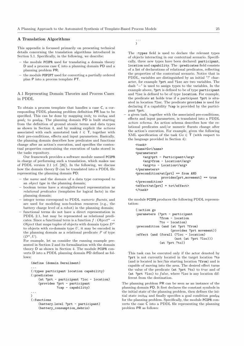
A Planning Approach to the Automated Synthesis of Template-Based Process Models 25
A Translation Algorithms
This appendix is focussed primarily on presenting technicaldetails concerning the translation algorithms introduced inSection 5.1. Specifically, in the following, we describe:
– the module PC2PR used for translating a domain theoryD and a process case C into a planning domain PD and aplanning problem PR;
– the module POP2PT used for converting a partially orderedplan P into a process template PT.
A.1 Representing Domain Theories and Process Cases
in PDDL
To obtain a process template that handles a case C, a cor-responding PDDL planning problem definition PR has to bespecified. This can be done by mapping initC to initPR andgoalC to goalPR. The planning domain PD is built startingfrom the definition of ground atomic terms and data typesas shown in Section 4, and by making explicit the actionsassociated with each annotated task t ∈ T, together withtheir pre-conditions, effects and input parameters. Basically,the planning domain describes how predicates and functionschange after an action’s execution, and specifies the contex-tual properties constraining the execution of tasks stored inthe tasks repository.
Our framework provides a software module named PC2PR
in charge of performing such a translation, which makes useof PDDL version 2.1 (cf. [26]). In the following, we discusshow the domain theory D can be translated into a PDDL filerepresenting the planning domain PD:
– the name and the domain of a data type correspond toan object type in the planning domain;
– boolean terms have a straightforward representation asrelational predicates (templates for logical facts) in theplanning domain;
– integer terms correspond to PDDL numeric fluents, andare used for modeling non-boolean resources (e.g., thebattery charge level of a robot) in the planning domain;
– functional terms do not have a direct representation inPDDL 2.1, but may be represented as relational predi-cates. Since a functional term is a function f : Objectn →Object that maps tuples of objects with domain types Dn
to objects with co-domain type U , it may be encoded inthe planning domain as a relational predicate P of type(Dn, U).For example, let us consider the running example pre-sented in Section 2 and its formalization with the domaintheory D as shown in Section 4. The module PC2PR con-verts D into a PDDL planning domain PD defined as fol-lows:
(define (domain Derailment)
...
(:types participant location capability)
(:predicates
(at ?prt - participant ?loc - location)
(provides ?prt - participant
?cap - capability)
...
)
(:functions
(battery level ?prt - participant)
(battery_consumption_debris)
...
)
The :types field is used to declare the relevant typesof objects interacting in our contextual scenario. Specifi-cally, three new types have been declared: participant,location and capability. The :predicates field consistsof a list of declarations of relational predicates, reflectingthe properties of the contextual scenario. Notice that inPDDL, variables are distinguished by an initial ′?′ char-acter, for example ?prt and ?loc are two variables. Thedash ′−′ is used to assign types to the variables. In theexample above, ?prt is defined to be of type participant
and ?loc is defined to be of type location. For example,the predicate at holds true if a participant ?prt is situ-ated in location ?loc. The predicate provides is used fordeclaring if a capability ?cap is provided by the partici-pant ?prt.
– a given task, together with the associated pre-conditions,effects and input parameters, is translated into a PDDLaction schema. An action schema describes how the re-lational predicates and/or numeric fluents change afterthe action’s execution. For example, given the followingXML specification of the task Go ∈ T (with respect tothe language provided in Section 4):
<task>
<name>Go</name>
<parameters>
<arg>prt - Participant</arg>
<arg>from - Location</arg>
<arg>to - Location</arg>
</parameters>
<precondition>at[prt] == from AND
provides[prt,movement] == true
</precondition>
<effect>at[prt] = to</effect>
</task>
the module PC2PR produces the following PDDL represen-tation:
(:action go
:parameters (?prt - participant
?from - location
?to - location)
:precondition (and (at ?prt ?from)
(provides ?prt movement))
:effect (and (forall (?loc - location)
(not (at ?prt ?loc)))
(at ?prt ?to))
This task can be executed only if the actor denoted by?prt is not currently located in the target location ?to
(and is located in her/his starting location ?from) and iscapable of moving into the area. The desired effect turnsthe value of the predicate (at ?prt ?to) to true and of(at ?prt ?loc) to false, where ?loc is any location dif-ferent from the destination.
The planning problem PR can be seen as an instance of theplanning domain PD. It first declares the constant symbols inthe initial state of the planning problem, then defines the ini-tial state initPR and finally specifies a goal condition goalPRfor the planning problem. Specifically, the module PC2PR con-verts the case C into a PDDL file representing the planningproblem PR as follows:
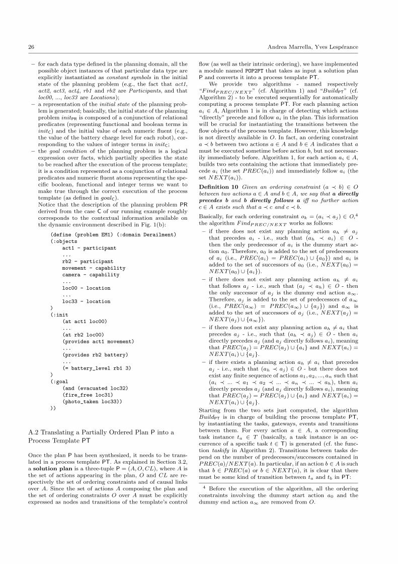
26 Andrea Marrella, Yves Lesperance
– for each data type defined in the planning domain, all thepossible object instances of that particular data type areexplicitly instantiated as constant symbols in the initialstate of the planning problem (e.g., the fact that act1,act2, act3, act4, rb1 and rb2 are Participants, and thatloc00, ..., loc33 are Locations);
– a representation of the initial state of the planning prob-lem is generated; basically, the initial state of the planningproblem initPR is composed of a conjunction of relationalpredicates (representing functional and boolean terms ininitC) and the initial value of each numeric fluent (e.g.,the value of the battery charge level for each robot), cor-responding to the values of integer terms in initC;
– the goal condition of the planning problem is a logicalexpression over facts, which partially specifies the stateto be reached after the execution of the process template;it is a condition represented as a conjunction of relationalpredicates and numeric fluent atoms representing the spe-cific boolean, functional and integer terms we want tomake true through the correct execution of the processtemplate (as defined in goalC).Notice that the description of the planning problem PRderived from the case C of our running example roughlycorresponds to the contextual information available onthe dynamic environment described in Fig. 1(b):
(define (problem EM1) (:domain Derailment)
(:objects
act1 - participant
...
rb2 - participant
movement - capability
camera - capability
...
loc00 - location
...
loc33 - location
)
(:init
(at act1 loc00)
...
(at rb2 loc00)
(provides act1 movement)
...
(provides rb2 battery)
...
(= battery_level rb1 3)
)
(:goal
(and (evacuated loc32)
(fire_free loc31)
(photo_taken loc33))
))
A.2 Translating a Partially Ordered Plan P into a
Process Template PT
Once the plan P has been synthesized, it needs to be trans-lated in a process template PT. As explained in Section 3.2,a solution plan is a three-tuple P = (A,O,CL), where A isthe set of actions appearing in the plan, O and CL are re-spectively the set of ordering constraints and of causal linksover A. Since the set of actions A composing the plan andthe set of ordering constraints O over A must be explicitlyexpressed as nodes and transitions of the template’s control
flow (as well as their intrinsic ordering), we have implementeda module named POP2PT that takes as input a solution planP and converts it into a process template PT.
We provide two algorithms - named respectively“FindPREC/NEXT ” (cf. Algorithm 1) and “BuildPT” (cf.Algorithm 2) - to be executed sequentially for automaticallycomputing a process template PT. For each planning actionai ∈ A, Algorithm 1 is in charge of detecting which actions“directly” precede and follow ai in the plan. This informationwill be crucial for instantiating the transitions between theflow objects of the process template. However, this knowledgeis not directly available in O. In fact, an ordering constrainta ≺ b between two actions a ∈ A and b ∈ A indicates that amust be executed sometime before action b, but not necessar-ily immediately before. Algorithm 1, for each action ai ∈ A,builds two sets containing the actions that immediately pre-cede ai (the set PREC(ai)) and immediately follow ai (theset NEXT (ai)).
Definition 10 Given an ordering constraint (a ≺ b) ∈ Obetween two actions a ∈ A and b ∈ A, we say that a directlyprecedes b and b directly follows a iff no further actionc ∈ A exists such that a ≺ c and c ≺ b.
Basically, for each ordering constraint ok = (ai ≺ aj) ∈ O,4
the algorithm FindPREC/NEXT works as follows:
– if there does not exist any planning action ah 6= aj
that precedes ai - i.e., such that (ah ≺ ai) ∈ O -then the only predecessor of ai is the dummy start ac-tion a0. Therefore, a0 is added to the set of predecessorsof ai (i.e., PREC(ai) = PREC(ai) ∪ a0) and ai isadded to the set of successors of a0 (i.e., NEXT (a0) =NEXT (a0) ∪ ai).
– if there does not exist any planning action ah 6= ai
that follows aj - i.e., such that (aj ≺ ah) ∈ O - thenthe only successor of aj is the dummy end action a∞.Therefore, aj is added to the set of predecessors of a∞(i.e., PREC(a∞) = PREC(a∞) ∪ aj) and a∞ isadded to the set of successors of aj (i.e., NEXT (aj) =NEXT (aj) ∪ a∞).
– if there does not exist any planning action ah 6= ai thatprecedes aj - i.e., such that (ah ≺ aj) ∈ O - then ai
directly precedes aj (and aj directly follows ai), meaningthat PREC(aj) = PREC(aj) ∪ ai and NEXT (ai) =NEXT (ai) ∪ aj.
– if there exists a planning action ah 6= ai that precedesaj - i.e., such that (ah ≺ aj) ∈ O - but there does notexist any finite sequence of actions a1, a2, ..., an such that(ai ≺ ... ≺ a1 ≺ a2 ≺ ... ≺ an ≺ ... ≺ ah), then ai
directly precedes aj (and aj directly follows ai), meaningthat PREC(aj) = PREC(aj) ∪ ai and NEXT (ai) =NEXT (ai) ∪ aj.
Starting from the two sets just computed, the algorithmBuildPT is in charge of building the process template PT,by instantiating the tasks, gateways, events and transitionsbetween them. For every action a ∈ A, a correspondingtask instance ta ∈ T (basically, a task instance is an oc-currence of a specific task t ∈ T) is generated (cf. the func-tion taskify in Algorithm 2). Transitions between tasks de-pend on the number of predecessors/successors contained inPREC(a)/NEXT (a). In particular, if an action b ∈ A is suchthat b ∈ PREC(a) or b ∈ NEXT (a), it is clear that theremust be some kind of transition between ta and tb in PT:
4 Before the execution of the algorithm, all the orderingconstraints involving the dummy start action a0 and thedummy end action a∞ are removed from O.
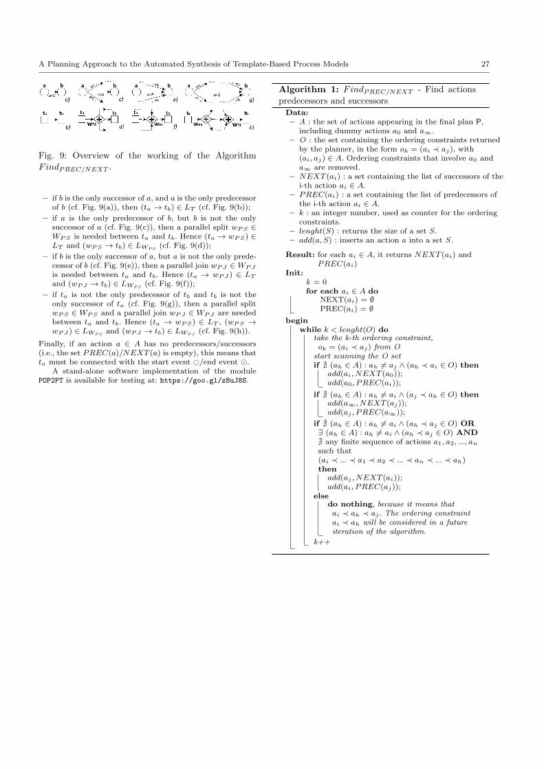
A Planning Approach to the Automated Synthesis of Template-Based Process Models 27
Fig. 9: Overview of the working of the Algorithm
FindPREC/NEXT .
– if b is the only successor of a, and a is the only predecessorof b (cf. Fig. 9(a)), then (ta → tb) ∈ LT (cf. Fig. 9(b));
– if a is the only predecessor of b, but b is not the onlysuccessor of a (cf. Fig. 9(c)), then a parallel split wPS ∈WPS is needed between ta and tb. Hence (ta → wPS) ∈LT and (wPS → tb) ∈ LWPS
(cf. Fig. 9(d));
– if b is the only successor of a, but a is not the only prede-cessor of b (cf. Fig. 9(e)), then a parallel join wPJ ∈WPJ
is needed between ta and tb. Hence (ta → wPJ ) ∈ LT
and (wPJ → tb) ∈ LWPJ(cf. Fig. 9(f));
– if ta is not the only predecessor of tb and tb is not theonly successor of ta (cf. Fig. 9(g)), then a parallel splitwPS ∈ WPS and a parallel join wPJ ∈ WPJ are neededbetween ta and tb. Hence (ta → wPS) ∈ LT , (wPS →wPJ ) ∈ LWPS
and (wPJ → tb) ∈ LWPJ(cf. Fig. 9(h)).
Finally, if an action a ∈ A has no predecessors/successors(i.e., the set PREC(a)/NEXT (a) is empty), this means thatta must be connected with the start event #/end event .
A stand-alone software implementation of the modulePOP2PT is available for testing at: https://goo.gl/z8uJ8S.
Algorithm 1: FindPREC/NEXT - Find actions
predecessors and successors
Data:– A : the set of actions appearing in the final plan P,
including dummy actions a0 and a∞.– O : the set containing the ordering constraints returned
by the planner, in the form ok = (ai ≺ aj), with(ai, aj) ∈ A. Ordering constraints that involve a0 anda∞ are removed.
– NEXT (ai) : a set containing the list of successors of thei-th action ai ∈ A.
– PREC(ai) : a set containing the list of predecessors ofthe i-th action ai ∈ A.
– k : an integer number, used as counter for the orderingconstraints.
– lenght(S) : returns the size of a set S.– add(a, S) : inserts an action a into a set S.
Result: for each ai ∈ A, it returns NEXT (ai) andPREC(ai)
Init:k = 0for each ai ∈ A do
NEXT(ai) = ∅PREC(ai) = ∅
beginwhile k < lenght(O) do
take the k-th ordering constraint,ok = (ai ≺ aj) from O
start scanning the O setif @ (ah ∈ A) : ah 6= aj ∧ (ah ≺ ai ∈ O) then
add(ai, NEXT (a0));add(a0, PREC(ai));
if @ (ah ∈ A) : ah 6= ai ∧ (aj ≺ ah ∈ O) thenadd(a∞, NEXT (aj));add(aj , PREC(a∞));
if @ (ah ∈ A) : ah 6= ai ∧ (ah ≺ aj ∈ O) OR∃ (ah ∈ A) : ah 6= ai ∧ (ah ≺ aj ∈ O) AND@ any finite sequence of actions a1, a2, ..., an
such that(ai ≺ ... ≺ a1 ≺ a2 ≺ ... ≺ an ≺ ... ≺ ah)then
add(aj , NEXT (ai));add(ai, PREC(aj));
elsedo nothing, because it means thatai ≺ ah ≺ aj . The ordering constraintai ≺ ah will be considered in a futureiteration of the algorithm.
k++
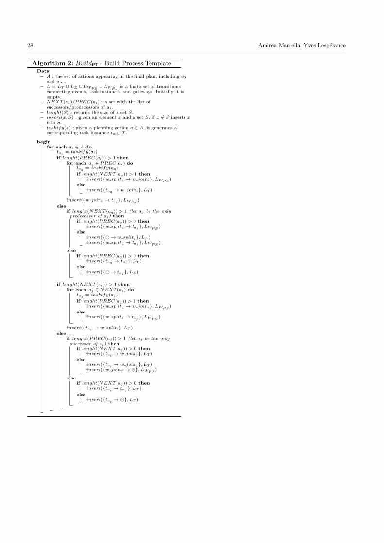
28 Andrea Marrella, Yves Lesperance
Algorithm 2: BuildPT - Build Process TemplateData:– A : the set of actions appearing in the final plan, including a0
and a∞.– L = LT ∪ LE ∪ LWPS
∪ LWPJis a finite set of transitions
connecting events, task instances and gateways. Initially it isempty.
– NEXT (ai)/PREC(ai) : a set with the list ofsuccessors/predecessors of ai.
– lenght(S) : returns the size of a set S.– insert(x, S) : given an element x and a set S, if x /∈ S inserts x
into S.– taskify(a) : given a planning action a ∈ A, it generates a
corresponding task instance ta ∈ T .
beginfor each ai ∈ A do
tai= taskify(ai)
if lenght(PREC(ai)) > 1 thenfor each aq ∈ PREC(ai) do
taq = taskify(aq)
if lenght(NEXT (aq)) > 1 theninsert(w splitq → w joini, LWPS
)
elseinsert(taq → w joini, LT )
insert(w joini → tai, LWPJ
)
elseif lenght(NEXT (aq)) > 1 (let aq be the onlypredecessor of ai) then
if lenght(PREC(aq)) > 0 theninsert(w splitq → tai
, LWPS)
elseinsert(#→ w splitq, LE)insert(w splitq → tai
, LWPS)
elseif lenght(PREC(aq)) > 0 then
insert(taq → tai, LT )
elseinsert(#→ tai
, LE)
if lenght(NEXT (ai)) > 1 thenfor each aj ∈ NEXT (ai) do
taj= taskify(aj)
if lenght(PREC(aj)) > 1 theninsert(w splitq → w joini, LWPS
)
elseinsert(w spliti → taj
, LWPS)
insert(tai→ w spliti, LT )
elseif lenght(PREC(aj)) > 1 (let aj be the onlysuccessor of ai) then
if lenght(NEXT (aj)) > 0 theninsert(tai
→ w joinj, LT )
elseinsert(tai
→ w joinj, LT )insert(w joinj → , LWPJ
)
elseif lenght(NEXT (aj)) > 0 then
insert(tai→ taj
, LT )
elseinsert(tai
→ , LT )