Embed Size (px)
Citation preview
1
Template-based Parameterized Synthesis of UniformInstruction-Level Abstractions for SoC Verification
Pramod Subramanyan, Bo-Yuan Huang, Yakir Vizel, Aarti Gupta, and Sharad Malik
Abstract—Modern system-on-chip (SoC) designs comprise pro-grammable cores, application-specific accelerators and I/O de-vices. Accelerators are controlled by software/firmware and func-tionality is implemented by this combination of programmablecores, firmware, and accelerators. Verification of such SoCs ischallenging, especially for system-level properties maintained bya combination of firmware and hardware. Attempting to formallyverify the full SoC design with both firmware and hardware isnot scalable, while separate verification can miss bugs.
A general technique for scalable system-level verification isto construct an abstraction of SoC hardware and verify firm-ware/software using it. There are two challenges in applyingthis technique in practice. Constructing the abstraction to cap-ture required details and interactions is error-prone and time-consuming. The second is ensuring abstraction correctness sothat properties proven with it are valid.
This paper introduces a methodology for SoC design andverification based on the synthesis of instruction-level abstrac-tions (ILAs). The ILA is an abstraction of SoC hardwarewhich models updates to firmware-visible state at the granu-larity of instructions. For hardware accelerators, the ILA isanalogous to the instruction-set architecture (ISA) definition forprogrammable processors and enables scalable verification offirmware interacting with hardware accelerators. To alleviatethe disadvantages of manual construction of abstractions, weintroduce two algorithms for synthesis of ILAs from partialdescription called templates. We then show how the ILA canbe verified to be correct. We evaluate the methodology using asmall SoC design consisting of the 8051 microcontroller and twocryptographic accelerators. The methodology uncovered 15 bugs.
Index Terms—system-on-chip, systems modeling, formal veri-fication, accelerator architectures, model checking
I. INTRODUCTION
The end of Dennard-scaling [8] has led to power andthermal constraints limiting performance of ICs. We are nowin the era of “dark silicon” where significant parts of an ICmust be powered-off in order to stay within its power andthermal budgets [10]. Despite the technological limitationsimposed by the dark silicon era, the demand for increasedperformance and energy-efficiency has not subsided and thishas led to rise of accelerator-rich system-on-chip (SoC) archi-tectures [5]. Application-specific functionality is implementedusing fixed-function or semi-programmable accelerators for
Pramod Subramanyan is with the Department of Electrical Engineeringand Computer Sciences, University of California, Berkeley. Bo-Yuan Huang,Yakir Vizel, Sharad Malik are with the Department of Electrical Engineering,Princeton University. Aarti Gupta is with the Department of ComputerScience, Princeton University.
This work was supported by in part by C-FAR, one of six SRC STARnetCenters, sponsored by MARCO and DARPA and a research gift from IntelCorporation.
increased performance and energy-efficiency. As a result,modern SoC designs contain a number of programmable cores,semi-programmable accelerators, I/O devices and memories.Modern SoCs also contain firmware; this executes on pro-grammable cores, interacts closely with hardware and orches-trates operation of accelerators and I/O devices.
A. Challenges in SoC VerificationThe prevalence of firmware and the emergence of
accelerator-rich architectures have introduced new challengesin SoC verification. These are described below.Challenges due to Firmware: Firmware lies between theoperating system and hardware and interacts closely with thehardware. Firmware and hardware make many assumptionsabout the behavior of the other component. As a result,verifying the two separately requires explicitly enumeratingthese assumptions and verifying that the other component sat-isfies them. An example from a commercial SoC highlightingthe importance of capturing these interactions is provided in[35]. A series of I/O write operations could be executed bymalicious firmware leaving an accelerator in a “confused” stateafter which sensitive cryptographic keys could be exfiltrated.The bug was because implicit assumptions made by hardwareabout the timing of firmware I/O writes were violated bythe malicious code. This points to the need for scalable co-verification of SoC hardware and firmware.Challenges due to Accelerator-Rich SoCs: The emer-gence of accelerator-rich SoC architectures has obsoletedexisting hardware/software (HW/SW) and hardware/firmware(HW/FW) abstractions. In the past, programmable hardwaremeant a programmable core and this was modeled using thecore’s instruction-set architecture (ISA) specification. Softwarecould be compiled, verified, and reasoned about using thisISA-specification. However, with the proliferation of semi-programmable accelerators in today’s SoCs, the ISA abstrac-tion is inadequate at the system-level. System functionalitymay now be implemented using accelerators and so an ISA-centric view of execution is incomplete. Firmware typicallycontrols and interacts with accelerators by executing memory-mapped I/O (MMIO) reads and writes. These MMIO readsand writes are commands to the accelerator to perform variousfunctions. For example, a command could instruct an acceler-ator to fetch a block of data from memory, encrypt it using aspecified key and write the result back to memory. However,from the perspective of the ISA, all that has occurred is an I/Owrite. Therefore, there is an important need for abstractionsthat model the HW/FW and HW/SW interfaces presented byaccelerators in modern SoC designs.

2
B. Abstractions for SoC Verification
Aggressive time-to-market requirements mean firmware andsoftware for SoCs must be designed before hardware isready. This requires models of SoC hardware. In practice,such models are usually transaction-level models (TLMs) ofSoC components written in SystemC [4, 28, 39]. TLMs di-vide SoC computations into transactions and application-levelfunctionality is implemented as a sequence of transactions.While TLMs are important, it is difficult to assign system-level meaning and precise semantics to transactions written inSystemC. Furthermore, TLMs can be quite detailed and formalanalysis of the TLM along with firmware is challenging.
TLMs illustrate one instantiation of a general solution tothe modelling problem: construction of abstractions of SoChardware. An abstraction of SoC functionality is constructedand when verifying properties involving firmware, the abstrac-tion is used instead of the bit-precise cycle-accurate hardwaremodel. Verification using the abstraction is more scalablebecause irrelevant firmware-invisible details are not includedin the abstraction. While the general technique is well-known,we are aware of only a few efforts that have applied this to theco-verification of SoC hardware and firmware [27, 31, 45, 46].
Although the idea of constructing abstractions for firmwareverification is attractive, it is challenging to apply in practice.Firmware interacts with hardware components in a myriad ofways. For the abstraction to be useful, it needs to model allinteractions and capture all updates to firmware-visible state.• Firmware usually controls accelerators in the SoC by
writing to memory-mapped registers within the acceler-ators. These registers may set the mode of operation ofthe accelerator, the location of the data to be processed,or return the current state of the accelerator’s operation.The abstraction needs to model these “special” reads andwrites to the memory-mapped I/O space correctly.
• Once operation is initiated, accelerators step through ahigh-level state machine that implements the data pro-cessing functionality. Transitions of this state machinemay depend on responses from other SoC components,the acquisition of semaphores, external inputs, etc. Thesestate machines have to be modeled to ensure there areno bugs involving race conditions or malicious externalinput that cause unexpected transitions or deadlocks.
• Another concern is preventing compromised/maliciousfirmware from accessing sensitive data. To prove thatsuch requirements are satisfied, the abstraction needs tocapture issues such as a sensitive value being copied intoa firmware-visible temporary register.
Manually constructing an abstraction which captures thesedetails, as proposed for example in [45, 46], is not practicalbecause it is error-prone, as well as tedious and very time-consuming. Abstractions that focus on specific types of proper-ties, like the control flow graph from [27], can address certainverification concerns, but do not capture all of the aboverequirements. A third alternative is to verify the firmwareusing a software/SystemC model of the hardware [4, 18, 39].This too misses bugs present in the hardware implementationbut not the SystemC model. The underlying problem with
these approaches is in correctness of the abstraction. If thehardware implementation is not consistent with the abstraction,properties proven using it are not valid.
C. Instruction-Level Abstractions for SoC Verification
In this paper, we propose a general methodology for SoCverification based on the construction of abstractions of hard-ware components that capture updates to all firmware-visiblestate. We call such abstractions instruction-level abstractions(ILAs) and propose techniques for semi-automatic synthesisof ILAs and verification of their correctness.Instruction-Level Abstractions: An instruction-level abstrac-tion (ILA) of a hardware component is an abstraction thatmodels all firmware-visible state variables and associated stateupdates in that component. In programmable cores, the ILAmodels all architectural registers, and in accelerators it modelsall memory-mapped and I/O addressable registers. The insightunderlying the ILA is that firmware only views changes insystem state at the granularity of instructions. So hardwarecomponents need only be modelled at this granularity.Uniform and Hierarchical ILAs: Accelerators in today’sSoCs perform computation in response to commands sentby programmable cores [5]. This computation is typicallybounded in length. Our insight is to view commands fromthe programmable cores to the accelerators as analogousto “instruction opcodes” and state-updates in response tothese commands as “instruction execution.” We propose auniform instruction-level abstraction (ILA) which models ac-celerators using the same fetch/decode/execute sequence as aprogrammable core. The command is analogous to “fetch,”the case-split determining how the command is processed is“decode,” and the state update is “execute.” Imposing thisstructure on an abstraction for accelerators allows firmwareinteractions with accelerators to be modeled using well-understood instruction-interleaving semantics, enabling use ofstandard tools like software model checkers. Verification ofSoC hardware is also easier because conformance with an ILAcan be checked compositionally on a “per-instruction” basisleveraging work in microprocessor verification [23, 25].
We also propose hierarchical instruction-level abstractionswhich allow the construction of compositional models of anaccelerator as consisting of a macroILA and possibly severalmicroILAs. The macroILA comprises a set of macroinstruc-tions, each of which may be implemented by a sequence ofmicroinstructions that comprise a microILA at a lower levelof abstraction. This is analogous to CISC (complex instructionset computer) instructions being implemented as a series ofmicroinstructions. Hierarchy helps manage complexity andmodels different levels of abstraction in hardware components.ILA Synthesis: Manual construction of ILAs is tedious anderror-prone. These challenges are exacerbated for third-partyIPs as ILAs have to be constructed post hoc from existingimplementations. Therefore, techniques for automated syn-thesis of ILAs are important. To address this challenge, wepropose techniques for the synthesis of ILAs from partialdescriptions known as templates. Instead of manually con-structing the complete abstraction, the verification engineer

3
Template ILA1
SynthesisAlgorithm
2
BlackboxSimulator3
CEGIS loop
ILA4
System-LevelVerification8
ModelChecker6
RTL Model5
RefinementRelations7
Firmware9
bugs/counterexamples
Fig. 1: Overview of the ILA-based SoC Verification Methodology.
now has an easier task of writing a template that partiallydefines the operation of hardware components. The synthesisframework infers the complete abstraction and fills in themissing details by using a blackbox simulator1 of the hardwarecomponent. Simulators are often constructed for SoC designand validation, e.g., for simulation-based testing of firmware.In principle, it may be possible to extract abstractions throughautomated analysis of such simulators. However, in practice,the scale and complexity of simulator codebases make thisinfeasible. Our work helps constructs ILAs in this scenario.The template abstraction, synthesis framework and blackboxsimulator are shown in boxes 1, 2 and 3 in Figure 1.ILA Verification: To validate the ILA and ensure that thehardware implementation is consistent with the ILA, a set oftemporal refinement relations are defined by the verificationengineer. These relations specify equivalence between ILAand the register-transfer level (RTL) hardware implementation.These refinement relations are verified using hardware modelchecking to ensure that RTL behavior matches the ILA. If therefinement relations are proven, we have a guarantee that theabstraction is a correct over-approximation of hardware andany properties proven using the abstraction are in fact valid.If the proof fails, we get counterexamples that can be used tofix either the implementation or the template. ILA verificationis shown in boxes 5, 6 and 7 in Figure 1.Methodology: Figure 1 is an overview of the methodology.Blue boxes (1 and 7) show the components that are providedby the verification engineer. We assume the RTL model and asimulator are already available; these are gray (boxes 3 and 5).Automatically generated artifacts are green (box 4) and off-the-shelf tools are red (boxes 6 and 8). The synthesis algorithm(box 2) is in yellow.
D. Contributions
We introduce a general methodology for template-basedsynthesis of instruction-level abstractions for SoC verification.The methodology has three advantages. It helps verificationengineers easily construct correct abstractions that are usefulin verifying system-level properties of SoCs.
We introduce a language for template-based synthesis thatis tailored to modeling hardware components in modern SoCs.
1The term blackbox simulator (also referred to as an I/O oracle [21]) meansthe simulator can be used to find the next state and outputs of the componentgiven a specific current state and input value.
We introduce two synthesis algorithms based on the counter-example guided inductive synthesis (CEGIS) paradigm [21,22]. Our first algorithm adapts CEGIS to our context – thesynthesis of SoC abstractions. Our second algorithm improvesupon this by taking advantage of the instruction-based struc-ture of the ILA and is up to 18× faster than the first algorithm.Together, these algorithms enable scalable synthesis of SoCILAs. Finally, we show how synthesized ILAs can be verifiedto be correct abstractions of SoC hardware.
We present a case study applying the methodology to theverification of a simple SoC design built from open-sourcecomponents. The SoC consists of the 8051 microcontrollerand two cryptographic accelerators. We discuss synthesis andverification of instruction-level abstractions in this SoC anddescribe the bugs found during verification. The methodologyhelped find a total of 15 bugs in the simulator and RTL.
This methodology was first presented in a conference arti-cle [38]. This journal paper introduces the notion of uniformand hierarchical ILAs (§II). While similar abstractions involv-ing fetch, decode and execute have been proposed before, ourcontribution is in showing how a uniform abstraction can beused for both processors and semi-programmable acclerators.This in turn allows us to build on work in software verificationto analyze programs that interact with accelerators. This paperalso introduces a novel parameterized synthesis algorithm(§IV) which is up to 18× faster (geometric mean 1.9×) thanthe algorithm presented in [38]. We also include new experi-mental results (§VI) that evaluate applicability of uniform andhierarchical ILAs and the new synthesis algorithm.
This paper describes synthesis and verification of ILAs, asopposed to system-level verification using ILAs (boxes 8 and9 in 1). An example of security-verification using ILAs inpart of a commercial SoC with a 32-bit microcontroller andother peripherals is published in [37]. ILA-based verificationwas successful in finding bugs in this commercial SoC.
II. INSTRUCTION-LEVEL ABSTRACTIONS
This section provides an overview of uniform and hierar-chical instruction-level abstractions (ILAs).
A. Architectural State and Inputs
The architectural state variables of an ILA are modelled asBoolean, bitvector or memory variables. As with ISAs, the

4
architectural state refers to state that is persistent and visibleacross instructions.
Let B = {0, 1} be the Boolean domain and let bvecldenote all bitvectors of width l. Mk×l : bveck → bveclmaps from bitvectors of width k to bitvectors of width l andrepresents memories of address width k bits and data width lbits. Booleans and bitvectors are used to model state registerswhile the memory variables model hardware structures likescratchpads and random access memories. A memory variablesupports two operations: read(mem, a) returns data stored ataddress a in memory mem . write(mem, a, d) returns a newmemory which is identical to mem except that address a mapsto d, i.e., read(write(mem, a, d), a) = d.
Let S represent the vector of state variables of an ILAconsisting of Boolean, bitvector and memory variables. Inan ILA for a microprocessor, S contains all the architecturalregisters, bit-level state (e.g., status flags), and data andinstruction memories. In an accelerator, S contains all thesoftware-visible registers and memory-structures. A state ofan ILA is a valuation of the variables in S.
Let vector W represent the input variables of the ILA; theseare Boolean and bitvector variables which model input portsof processors/accelerators.
Let typeS[i] be the “type” of state variable S[i]; typeS[i] =B if S[i] is Boolean, typeS[i] = bvecl if S[i] is a bitvector ofwidth l and typeS[i] = Mk×l if S[i] is a memory.
B. Fetch/Decode/Execute1) Fetching an Instruction: The result of fetching an in-
struction is an “opcode.” This is modelled by the functionFo : (S × W ) → bvecw, where w is the width of theopcode. For instance, in the 8051 microcontroller, Fo(S,W ) ,read(S[IMEM], S[PC]) where S[IMEM] is the instructionmemory and S[PC] is the program counter. We are using thenotation S[IMEM] to denote the fact that IMEM is a memberof the state vector S.
Programmable cores repeatedly fetch, decode and executeinstructions, i.e., they always “have” an instruction to execute.However, accelerators may be event-driven and execute aninstruction only when a certain trigger occurs. This is mod-elled by the function Fv : (S × W ) → B. For example,suppose an accelerator executes an instruction when eitherI[Cmd1Valid] or I[Cmd2Valid] is asserted, then Fv(S,W ) ,I[Cmd1Valid]∨ I[Cmd2Valid]. Here Cmd1Valid refers to aninput and the notation I[Cmd1Valid] denotes that this is amember of the input vector I .
2) Decoding an Instruction: Decoding an instruction in-volves examining an opcode and choosing the state updateoperation that will be performed. We represent the differentchoices by defining a set of functions D = {δj | 1 ≤ j ≤ C}for some constant C where each δj : bvecw → B. RecallFo : (S ×W ) → bvecw is a function that returns the currentopcode. Each δj is applied on the result of Fo. The functionsδj must satisfy the condition: ∀j, j′, S,W : j 6= j′ =⇒¬(δj(Fo(S,W ))∧ δj′(Fo(S,W ))); i.e., the functions δj use a“one-hot” encoding.
For convenience let us also define the predicate opj ,δj(Fo(S,W )). When opj is 1, it selects the jth instruction.
For example, in the case of the 8051 microcontroller, D ={δ1(f) , (f = 0), δ2(f) , (f = 1), . . . , δ256(f) , f =255}.2 Recall we had defined Fo for this microcontroller asFo(S,W ) , read(S[IMEM], S[PC]). Therefore, opj ⇐⇒read(S[IMEM], S[PC]) = (j − 1). We are “case-splitting”on each of the 256 values taken by the opcode and eachof these performs a different state update. The functions δjchoose which of these updates is to be performed.
3) Executing an Instruction: For each state element S[i]define the function Nj [i] : (S × W ) → typeS[i]. Nj [i]is the state update function for S[i] when opj = 1. Forexample, in the 8051 microcontroller, opcode 0x4 incrementsthe accumulator. Therefore, N4[ACC] = ACC + 1.
The complete next state function N : (S × W ) → S isdefined in terms of the functions Nj [i] over all i and j.
C. Hierarchical ILAs
Hierarchical ILAs handle different levels of abstraction inhardware components and allow ILAs to contain other ILAs.We call the inner ILAs microILAs while the outer/parentILA is called a macroILA. Each microILA has its own stateand input variables, fetch, decode and next state functions:Sµ,Wµ, Fµo , Fµv , Dµ and Nµ respectively. Each microILAis associated with a Valid function V µ : S × W → Bwhere S and W are the state and input variables of themacroILA containing it. V µ = 1 iff the valuation of the statevariables Sµ is legal, and the microILA only executes whenV µ = 1 MacroILAs and microILAs execute concurrently andasynchronously.
Communication between the macro and micro ILAs hap-pens in two ways. The microILA can read all macro-stateand use these in its next state computations. Similarly, themacroILA can read microILA state when V µ = 1 and usethese variables in the macroILA’s next state computation.
An example of hierarchical ILAs in our experimentalplatform is an ILA for an accelerator that implements theAdvanced Encryption Standard (AES) algorithm. The AESaccelerator has two parts. One part contains the configurationregisters and the processor core interface. The other is a statemachine that repeatedly fetches data from the shared RAM,encrypts it and writes back the encrypted data. We modelthe encryption state machine as a microILA, and each statein it is modeled as a “microinstruction.” The interface thatinteracts with the processor and controls the state machine isthe macroILA.
D. Putting it all Together
To summarize, an instruction-level abstraction (ILA) is thetuple: A = 〈S,W,Fo, Fv, D,N,Lµ〉. S and W are the stateand input variables. Fo, Fv, D and N are the fetch, decode andnext state functions respectively. Lµ = {(V µp , Aµp), ...} is aset of microILAs contained within this ILA. V µp : (S×W )→B is the valid function associated with the microILA Aµp .
2We are abusing notation here by writing elements of bvec8 as 0 . . . 255.

5
E. Syntax
The language of expressions allowed in Fo, Fv, D andNj [i] is shown in Figure 2. Expressions are quantifier-freeformulas over the theories of bitvectors, bitvector arrays anduninterpreted functions. They can be of type Boolean, bitvectoror memory, and each of these has the usual variables, constantsand operators with standard interpretations. The synthesisprimitives, shown in bold, will be described in §III.
〈exp〉 ::= 〈bv-exp〉 | 〈bool-exp〉 | 〈mem-exp〉 | 〈func-exp〉| 〈choice-exp〉
〈bv-exp〉 ::= var 〈id〉 width | cnst val width| bvop 〈exp〉 ...| read 〈memexp〉 〈addrexp〉| read-block 〈memexp〉 〈addrexp〉| apply 〈func〉 〈bv-exp〉 ...| extract-bitslice 〈bv-exp〉 width| extract-subword 〈bv-exp〉 width| replace-bitslice 〈bv-exp〉 〈bv-exp〉| replace-subword 〈bv-exp〉 〈bv-exp〉| in-range 〈bv-exp〉 〈bv-exp〉
〈bool-exp〉 ::= var | true | false| boolop 〈exp〉 ...
〈mem-exp〉 ::= 〈id〉 || write 〈mem-exp〉 〈bv-exp〉 〈bv-exp〉| write-block 〈mem-exp〉 〈bv-exp〉 〈bv-exp〉
〈func-exp〉 ::= func 〈id〉 widthout widthin1 ...
〈choice-exp〉 ::= choice 〈exp〉 〈exp〉 ...
Fig. 2: Syntax for Expressions
III. ILA SYNTHESIS
The goal of ILA synthesis is to help semi-automaticallysynthesize the functions Nj [i]. To do this, we build on workin oracle-guided program synthesis [21, 22]. In particular, weassume availability of a simulator that models state updatesperformed by the accelerator. In practice, this simulator canbe either an RTL description of the hardware component, ora high-level C/C++/SystemC simulator. Note this is a black-box simulator, also called an I/O oracle, which can be used tosimulate the execution of a component given an initial stateand an assignment to the component’s inputs.
A. Notation and Problem Statement
Let Sim : (S × W ) → S be the I/O oracle for the nextstate function N . Define Simi : (S ×W ) → typeS[i] to bethe function that projects the state element S[i] from Sim .3 Inorder to help synthesize the function implemented by Simi,the SoC designers write a template next state function, denotedby Ti : (Φ× S ×W )→ typeS[i].
Φ is a set of synthesis variables, also referred to as“holes” [33], and different assignments to Φ result in differentnext state functions. Unlike N [i], Ti is a partial descriptionand is therefore easier to write. It can omit certain low-level
3Simi(S,W ) = Sim(S,W )[i].
details, such as the mapping between individual opcodes andoperations, opcode bits and source and destination registers,etc. These details are filled-in by the counter-example guidedinductive synthesis (CEGIS) algorithm by observing the outputof Simi for carefully selected values of (S,W ).(Problem Statement: ILA Synthesis): For each state elementS[i] and each opj , find an interpretation of Φ, Φij , such that∀S,W : opj =⇒ (Ti(Φij , S,W ) = Simi(S,W ))).
Note the synthesis procedure is repeated for each instruction(each j) and each state element (each i), and the correspondingsynthesis result is Φij .
B. Template Language
The template identifies: (i) elements of architectural state,(ii) components of each instruction: the fields and ranges on/inwhich the instruction operates, (iii) a skeleton of possible stateupdates, and (iv) the direction of data-flow. Most importantly,the template implicitly decouples the orthogonal concerns ofprecisely matching low-level bitfields in order to identify op-codes and the state updates performed by each opcode. In ourexperience, these tightly-coupled concerns are often the mosterror-prone and tedious parts of manual model construction.
The synthesis primitives in the currently implemented tem-plate language are shown in bold in Figure 2. Note ouralgorithms/methodology are not dependent on these specificsynthesis primitives. The only requirement placed on theprimitives is that they can be “compiled” to some quantifier-free formula over bitvectors, arrays and uninterpreted func-tions. These theories are typically supported in all modernsatisfiability modulo theory (SMT) solvers, e.g., Z3 [7].Synthesis Primitives: The expression choice ε1 ε2 asks thesynthesizer to replace the choice primitive with either ε1 orε2 based on simulation results. choice ε1 ε2 is translated tothe formula ITE(φb, ε1, ε2) where φb ∈ Φ is a new Booleanvariable associated with this instance of the choice primitive.Its value is determined by the synthesis procedure.
The primitives extract-slice and extract-subword, synthe-size bitvector extract operators. The synthesis process deter-mines the indices to be extracted from. The replace-slice andreplace-subword are the counterparts of these primitives; theyreplace a part of the bitvector with an argument expression.The primitive in-range synthesizes a bitvector constant that iswithin the specified range. Adding new synthesis primitives iseasy and straightforward in our framework.
C. An Illustrative Example
We illustrate the definition of an ILA and template next statefunction using the processor shown in Figure 3. The instructionto be executed is read from the ROM. Its operands can eitherbe an immediate value (data) from the ROM or from the 4-entry register file. For simplicity, we assume that the onlytwo operations supported by the processor are addition andsubtraction.
The architectural state for the processor is S =〈ROM,PC,R0,R1,R2,R3〉 and input set W is empty.typeROM = M8×8 while all the other variables are of typebvec8. The opcode which determines the next instruction is

6
ALU
ROM
R
3
R
2
R
1
R
0
op
P
C+1
+1
res
src2
src1
a1
a2
d2
d1
Fig. 3: A simple processor for illustration.
stored in the ROM and so Fo , read(ROM,PC); Fv , 1.D = {δj | 1 ≤ j ≤ 256} where each δj(f) , f = j−1.4 Thetemplate next state functions, TPC and TRi
, are as follows.
TPC = choice (PC + 1) (PC + 2)imm = read(ROM,PC + 1)src1 = choice R0 R1 R2 R3
src2 = choice R0 R1 R2 R3 immres = choice (src1 + src2) (src1 − src2)TRi
= choice res Ri (0 ≤ i ≤3)
Algorithm 1 CEGIS Algorithm
1: function SYNTHESIZEALL(T ,Sim)2: for all S[i] ∈ S do3: for all opj do4: Φij ← SYNCEGIS(opj , Ti,Simi)5: Nj [i](S,W )← Ti(Φij , S,W )6: end for7: end for8: end function9: function SYNCEGIS(opj , Ti,Simi)
10: k ← 111: R1 ← opj ∧ (θ ↔ (Ti(Φ1, S,W ) 6= Ti(Φ2, S,W )))12: while sat(Rk ∧ θ) do13: ∆← MODEL(S,W )(Rk ∧ θ) . get dist. input ∆14: O ← Simi(∆) . simulate ∆15: O1 ← (Ti(Φ1,∆) = O)16: O2 ← (Ti(Φ2,∆) = O)17: Rk+1 ← Rk ∧O1 ∧O2 . enforce output O for ∆18: k ← k + 119: end while20: if sat(Rk ∧ ¬θ) then21: return MODELΦ1
(Rk ∧ ¬θ)22: end if23: return ⊥24: end function
D. CEGIS Algorithm
The counter-example guided inductive synthesis (CEGIS)algorithm for synthesizing Nj [i] from template next state
4In the rest of this paper, we shall refer to the elements of the state vectoras ROM, PC etc., instead of S[ROM ] or S[PC] in order to keep notationuncluttered.
function Ti and the simulator Sim is shown in Algorithm 1.The function SYNTHESIZEALL calls SYNCEGIS for eachopj (the different “opcodes”) and each S[i] (each of element ofarchitectural state). In each case, SYNCEGIS returns Φij whichis used to compute the next state function as Nj [i](S,W ) =Ti(Φij , S,W ).
SYNCEGIS tries to find an interpretation of (S,W ), say∆, which for some two interpretations of Φ: Φ1 and Φ2,is such that Ti(Φ1,∆) 6= Ti(Φ2,∆). To understand thealgorithm, observe that Ti(Φ, S,W ) defines a family of next-state functions. Different functions are selected by differentassignments to Φ. The key idea is to repeatedly find distin-guishing inputs [21] while ensuring the simulation input/outputvalues observed thus far are satisfied. A distinguishing inputfor Φ1 and Φ2 is an assignment to S and W such that theTi(Φ1, S,W ) 6= Ti(Φ2, S,W ). The distinguishing input ∆ isfound in line 13. Next we use the simulator Simi to findthe correct output O and assert that the next distinguishinginput must satisfy the condition that the output for ∆ is O(lines 15, 16 and 17). When no more distinguishing inputs canbe found, then all assignments to S define the same transitionrelation and we pick one of these assignments in line 21.
IV. PARAMETERIZED SYNTHESIS
In this section, we present an improved synthesis algorithm.We start with a high-level discussion of how the algorithmworks before presenting its details.
A. Motivating Parameterized Synthesis
As the inner loop of SYNTHESIZEALL in Algorithm 1shows, SYNCEGIS is executed for each of the different de-code functions represented by opj . For the illustrative examplefrom §III-C, this means that we execute Algorithm 1 foreach opcode: {op1 ⇐⇒ read(ROM,PC) = 0, op2 ⇐⇒read(ROM,PC) = 1, . . . , op256 ⇐⇒ read(ROM,PC) =255}. Consider the synthesis of one element of architecturalstate: PC. Excluding a few instructions that operate on animmediate value, for most opcodes, the next state functionfor the PC is PC + 1.5 However, Algorithm 1 repeatedlyrediscovers the same next state function (PC+1) by computingnew distinguishing inputs and then pruning the search spaceaccording to the corresponding simulator outputs. Finding dis-tinguishing inputs is the most computationally expensive partof synthesis. The parameterized synthesis algorithm attemptsto avoid this computation as much as possible.
To understand how parameterized synthesis works, let usfirst consider a strawman proposal. For the first opcode, i.e.,when executing SYNCEGIS(op1, Ti,Simi) we will executeSYNCEGIS as usual. However, we will record the distin-guishing inputs, the corresponding simulator outputs and nextstate function computed by the algorithm. Let the sequenceof pairs of distinguishing inputs and simulator outputs be〈(∆1, O1), . . . , (∆k, Ok)〉. Now suppose we are executing
5 This is a common scenario. For all elements of architectural state, thereare often a few next state functions that occur across many different opcodes.For example, in the case of R0, the most common next state function is theidentity function R0.
7
∆1 = 〈ROM : [0],PC : 0,RF : (0, 0, 0x47, 0x1)〉
O1 = SimR0 (∆1) = 0
∆2 = 〈ROM : [0],PC : 0,RF : (0x47, 0xF, 0, 0)〉
O2b = SimR0(∆2) = 0x47O2a = SimR0 (∆2) = 0x8E
∆3b = 〈ROM : [1 7→ 0x80, else :
1], PC : 0,RF : (0x47, 0xF, 0, 0)〉
Na[R0] = R0 +R0
O3b = SimR0(∆2) = 0x80
Nb[R0] = R0
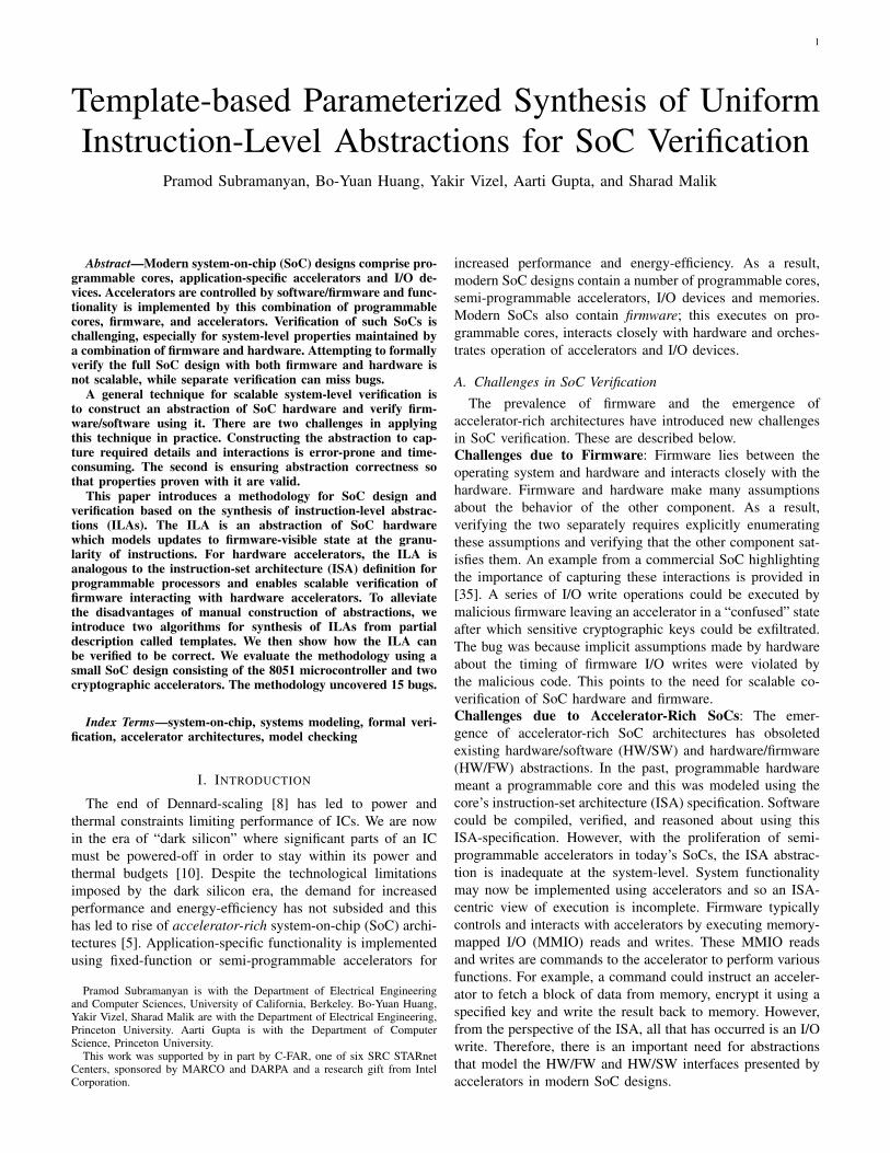
Fig. 4: Distinguishing Input Tree (DIT). The notation ROM =[0] means that all entries in the ROM map to value zero. Thenotation ROM = [0 7→ 1, else : 0x0] means that ROM address0 maps to 1, but all other addresses map to 0. The notationRF = (0, 0, 0x47, 0x1) refers to the valuation of the registerfile; it means that R0 = R1 = 0, R2 = 0x47 and R3 = 0x1.
SYNCEGIS(op2, Ti,Simi). The strawman proposal does notrecompute distinguishing inputs but instead presents the dis-tinguishing inputs computed for op1: 〈∆1, . . . ,∆k〉 to thesimulator and evaluates its output. Suppose these outputsare the same as those observed for op1: 〈O1, . . . , Ok〉. Thismeans the search space has been pruned identically and sothe next state functions are the same for both op2 and op1.If this occurs, the SMT solver need never be invoked for thecomputation of distinguishing inputs!
Unfortunately, this strawman proposal is flawed. This is be-cause the distinguishing inputs are computed for a specific opj :∆ |= opj ∧ (θ ↔ (Ti(Φ1, S,W ) 6= Ti(Φ2, S,W ))). However,∀j, j′ : j 6= j′ =⇒ ¬(opj ∧ opj′). The distinguishing inputsfor opj and op′j must be different. To make this idea work,we need a way of transforming distinguishing inputs computedfor opj into distinguishing inputs for opj′ . If we could do this,then we would not need to recompute distinguishing inputs ifthe next state function was “seen” before.
B. An Intuitive Explanation
We start with an explanation of the algorithm using aworked out example for the processor shown in §III-C.Figure 4 shows a distinguishing input tree (DIT). A distin-guishing input tree (DIT) consists of three types of nodes:(i) distinguishing input nodes (shown in red), (ii) simulatoroutputs (green), and (iii) symbolic expressions for the nextstate (blue). Each path from the root to a leaf node in thetree represents an equivalence class of semantically equivalentnext state functions (Nj [i]) and the distinguishing inputs andcorresponding outputs that occur along this path uniquelyidentify this next state function.
The tree shown in Figure 4 shows the computa-tion of Nj [R0] over different opj . Consider the path〈(∆1, O1), (∆2, O2a), Na[R0]〉 in Figure 4. This path startsat the root (∆1) and terminates at a leaf (Na[RA]). Itcorresponds to the computation of N1[R0] where op1 ⇐⇒
read(ROM,PC) = 0x0. For the first opcode (op1), pa-rameterized synthesis works identically to SYNCEGIS withthe only difference being that distinguishing inputs, simulatoroutputs and the next state function are inserted into the DIT.
Now suppose we are synthesizing N2[R0]. Recollect thatop2 ⇐⇒ read(ROM,PC) = 1. As described earlier,our goal is to reuse the previously computed distinguishinginput ∆1. The distinguishing characteristic of ∆1 is in theassignments to R0,R1,R2,R3 and read(ROM,PC + 1). Thedistinguishing nature does not depend on read(ROM,PC)which contains the opcode. We would be able to reuse thisdistinguishing input for op2 if we changed the assignmentto ROM such that read(ROM, 0) = 0x1 while “keepingeverything else the same.” The tricky part here is formalizing“keeping everything else the same.”
Let us consider a strawman proposal to achieve this. Sup-pose we use an SMT solver and find an assignment ROM′ suchthat ROM′ |= op2. One such assignment is all ROM addressesin ROM′ map to 1: ROM′ = [1]. Now consider the distinguishinginput ∆1′
, 〈ROM′ = [1],PC = 0,RF = (0, 0, 0x47, 0x7)〉.∆1′
is exactly the same as ∆1, except that ROM′ has beenchanged so that ROM′ |= op2. But ∆1′
and ∆1 are notequivalent in terms of distinguishing power. ∆1 can distinguishbetween the functions R3 +R3 and R3 +read(ROM,PC+1).The former evaluates to 2 while the latter evaluates to 1 underthe assignment ∆1. However, ∆1′
cannot distinguish betweenthese functions (both evaluate to 2) and is weaker in termsof distinguishing power than ∆1. Therefore, a more preciseformulation of “keeping everything else the same” involvesshowing that the new input does not weaken the originalassignment’s distinguishing power. The algorithm introducedin this section allows us to reuse distinguishing inputs bymaking simple syntactic substitutions while retaining the samedistinguishing power.
Let ∆1′= 〈ROM : [0 7→ 1, else : 0],PC : 0,RF :
(0, 0, 0x47, 0x1)〉 be a “minimally changed” version of ∆1.Note ∆1′
retains the distinguishing power of ∆1 while alsosatisfying op2. We call ∆1′
an SD-variant interpretation of∆1. A formal definition of SD-variant interpretations is inthe next section.6 Our algorithm computes SD-variant dis-tinguishing inputs by solving a simple SMT instance for thepredicate opj , and then performs a syntactic substitution onthe distinguishing inputs in the DIT.
Now suppose ∆1′results in the same output O1′
= 0
from the simulator. This means that the search space can bepruned in the same was with O1. Therefore, we continuefollowing this path in the DIT and compute the next SD-variant distinguishing input of ∆2. Now the simulator returnsan output we have not seen before. We insert this into thetree as node O2b. We are now on a new path in the tree anduse the SMT solver to compute distinguishing input ∆3b. Atthis point, we do not have any reusable information and thealgorithm devolves into CEGIS. And this eventually resultsin the computation of N2[R0] as R0. Now for all the otheropcodes which have the same next state function R0, we can
6S stands for support and D is the set of decode functions, so an SD-variantinterpretation varies only over the support of the decode functions.

8
just follow this path in the DIT instead of solving many morenew SMT instances.
C. Definitions
(Definition 1: Supporting Subexpressions) Let ε be anexpression and σ be some subexpression (some node in theabstract syntax tree) of ε. We say σ is a supporting subex-pression of ε if there exist ν1 and ν2 such that substituting σwith ν1 and ν2 in ε causes ε to differ: i.e., ε[σ/ν1] 6= ε[σ/ν2].In other words, σ is a subexpression that affects the valueof ε. For example, let ε , read(ROM,PC + 1) = 0. Thenν1 , PC + 1 is a supporting subexpression of ε.(Definition 2: Complete Set of Supporting Subexpressions)Let Sε = {σ1, . . . , σp, . . . , σL} be a set of supporting subex-pressions of ε. We say Sε is a complete set of supportingsubexpressions, if for all interpretations I1 and I2 of ε, ifJεKI1 6= JεKI2 then there exists some σp ∈ Sε such thatJσpKI1 6= JσpKI2 .7 In other words, if two interpretations differin the value of ε, then at least one of the expressions in acomplete set of supporting expressions of ε must also differ.Let us return to example of ε , read(ROM,PC + 1) = 0.The singleton set {read(ROM,PC+1)} is in fact a completeset of supporting subexpressions for ε. This is because ε is aBoolean, and if its truth value changes from 0 to 1 or viceversa, it must be because read(ROM,PC + 1) changed.
We can extend this definition to a set of expressionsE = {ε1, . . . , εq, . . . , εQ}. SE = {σ1, . . . , σp, . . . , σL} is acomplete set of supporting subexpressions for the set E if forall interpretations I1, I2 and all εq ∈ E, if JεqKI1 6= JεqKI2then there exists some σp ∈ SE such that JσpKI1 6= JσpKI2 .Consider the set of expression E , {read(ROM,PC) =0, read(ROM,PC) = 1, . . . , read(ROM,PC) = 255}. Thesingleton set SE , {read(ROM,PC)} is a complete set ofsupporting expressions for E. Any change in the truth valueof any element of E must necessarily be accompanied by achange in the valuation of the sole member of SE .(Definition 3: σp-variant Interpretations) Given a subex-pression σp, we say that two interpretations I1 and I2 areσp-variant if for all expressions ε, JεKI1 6= JεKI2 =⇒JσpKI1 6= JσpKI2 . In other words, if two interpretations areσp-variant, then they differ only in their assignments to σpand expressions that depend on σp and nothing else. Letσp , read(ROM,PC). Then the assignments ∆1 = 〈ROM :[0],PC : 0,RF : (0, 0, 0x47, 0x1)〉 and ∆1′
= 〈ROM : [0 7→1, else : 0],PC : 0,RF : (0, 0, 0x47, 0x1)〉 are σp-variant.
This definition can be extended to a set of subexpressionsSE . Two interpretations are SE-variant if for all expres-sions ε, if JεKI1 6= JεKI2 , there exists σp ∈ SE suchthat JσpKI1 6= JσpKI2 . If we define SE as the singletonset {read(ROM,PC)}, then ∆1 and ∆1′
as defined in theprevious paragraph are SE-variant.
D. Sketch of the Algorithm
Suppose we have a complete set of supporting subexpres-sions SD for the set of decode predicates {opj | 1 ≤ j ≤ C}.
7Notation JεKI refers to expression ε evaluated under interpretation I .
Algorithm 2 Parameterized synthesis
1: procedure SYNTHESIZEALL(D, T ,Sim)2: for all S[i] ∈ S do3: SD ← GETSUPPSET(D)4: reextract ← CHECKSUPPINVARIANT(Ti, SD)5: ∆t ← ⊥6: for all opj do7: if SD is non-empty then8: Nj [i]← SYNPARAM(opj , Ti,Simi,∆t)9: else
10: Nj [i]← SYNCEGIS(opj , Ti,Simi)11: end if12: end for13: end for14: end procedure1: function SYNPARAM(opj , Ti,Simi,∆t )2: k ← 13: R1 ← opj ∧ (θ ↔ (Ti(Φ1, S,W ) 6= Ti(Φ2, S,W )))4: while true do5: if ∆′ found in ∆t then6: ∆← FIXUP(∆′, opj)7: else8: ∆← MODEL(S,W )(Sk ∧ θ)9: end if
10: if ∆ = ⊥ then11: return EXTRACT(Rk)12: end if13: O ← Simi(∆)14: O1 ← (Ti(Φ1,∆) = O)15: O2 ← (Ti(Φ2,∆) = O)16: Rk+1 ← Rk ∧O1 ∧O2
17: if O not in ∆t then18: INSERT(∆t ,∆, O)19: end if20: end while21: end function
Now consider the template next state function Ti. Suppose forall SD-variant interpretations I1 and I2, JTiKI1 = JTiKI2 , thenwe say Ti is SD-invariant. TRi
are all SD invariant for thedefinitions given in §III-C.
The key insight is the following: if Ti is SD-invariant, givena set of distinguishing inputs ∆1,∆2, . . . ,∆k, all SD-variantsof these inputs will also prune the search space in the sameway (assuming of course that the simulator outputs are thesame for each of these inputs). Ti is SD-invariant, so it doesnot “depend” on the interpretation of the predicates opj . Thedistinguishing nature of ∆k is not “affected” by SD, thereforeit can be replaced by an SD-variant of itself.
The above suggests Algorithm 2. It starts by comput-ing a complete set of supporting expressions SD usingGETSUPPSET in line 3. In our current implementation, GET-SUPPSET returns a set containing bitvector and boolean vari-ables and expressions of the form read(M,addr) occurring inthe opj’s. The computation of SD need not always succeed. Inour implementation, we do not handle the case when the op-

9
code involves expressions involving modified memories; e.g.,read(write(M,addr1), addr2) and failover to SYNCEGIS.8
Line 4 checks if the template Ti is SD-invariant for theSD we computed. This is stored as the flag reextract . Itis important to note that even if Ti is not SD-invariant, wecan still speculatively reuse distinguishing inputs. However,in this case, we do need to verify that Rk ∧ θ is unsatisfiablewhen we reach the leaf node of the DIT. We then use eitherSYNPARAM or SYNCEGIS (if computation of SD failed) tocompute the Nj [i] for each opj .
Line 5 of SYNPARAM checks if we already have adistinguishing input in the DIT ∆t . If so, we find a SD-variant interpretation such that ∆ |= opj . This is done by theprocedure FIXUP in line 6. FIXUP finds a model for opj andthen performs a syntactic substitution on the distinguishinginput ∆′ in the tree. If we have reached a leaf node in thetree, we use EXTRACT to get the result of the synthesis. Inmost cases, EXTRACT just returns the function stored in theleaf node of the tree. However, if Ti was not SD-invariant(reextract = false) or if we are on a new path in the tree,EXTRACT uses the SMT solver to compute the result. tree.Note even if we are just following an existing path in theDIT, we update the formula Rk in lines 14-16. This is justthe construction of syntax trees for these formulas. The SMTsolver is not used to compute distuishing inputs using theRk unless we diverge from the outputs stored in the tree.Procedure INSERT adds a new output node to the DIT.
V. ILA CORRECTNESS AND VERIFICATION
In this section, we discuss correctness of the ILA synthe-sized by the algorithms presented in Sections III and IV, de-scribe why additional verification of the ILA may be necessaryand then describe how this verification is done.
A. Correctness of Synthesized ILA
The template next state function Ti represents a family ofpossible next state functions. The synthesis algorithms picka function from this family consistent with the I/O relationsexhibited by the simulator Sim . The synthesized result N isguaranteed to be correct if the next state function implementedby the simulator Sim is one of functions represented by thefamily Ti. We now formalize this notion of correctness.
1) Template Bugs: Consider the ILA A =〈S,W,Fo, Fv, D,N,Lµ〉 and the template next statefunction Ti. We say that Ti can express N if for all stateelements S[i] and each opj , there exists Φij such thatopj =⇒ Ti(Φij , S,W ) = Nj [i](S,W ).
We refer to the scenario when Ti cannot express N asa template bug because this occurs when the template nextstate function Ti has not been constructed correctly by theverification engineer. A template bug may result in the SMTsolver returning an unsatisfiable result when attempting tofind a distinguishing input. When this happens, our synthesisframework prints out the unsat core of Rk. In our experience,
8Note, this restriction only applies to the opcode (Fo from §II), not to thenext state function. This corner case does not occur in any of the designs inour evaluation.
examining the simulation inputs and outputs present in theunsat core is sufficient to identify the bug.
Unfortunately, a unsatisfiable result from the SMT solver isnot guaranteed if Ti cannot express N . In such a scenario, thealgorithm may also return an incorrect transition relation andthis will be discovered when verifying the ILA (see §V-B1).
2) Simulator Bugs: Since Sim models a simulator and real-world simulators may contain bugs, it is possible that Simis not equivalent to the idealized transition relation N , i.e.,Sim(S,W ) = N(S,W ) does not hold for all S and W . Thiswill also either cause an unsatisfiable result or an incorrecttransition relation. The former can be debugged using the unsatcore of Rk while the latter will be detected during verification.
3) Correctness of Synthesis: In the absence of template andsimulator bugs, we have the following result about correctnessof the synthesized next state functions.9
(Theorem 1) If Ti can express N and ∀S,W : Sim(S,W ) =N(S,W ) then for each state element S[i] and for each opj ,Algorithms 1 and 2 will terminate with result Φij and ∀S,W :opj =⇒ Ti(Φij , S,W ) = Nj [i](S,W ).
B. Verification of Synthesized ILAs
Once we have an ILA, the next step is to verify thatit correctly abstracts the hardware implementation. This isrequired because Theorem 1 only guarantees correctness ofsynthesis in the absence of template and simulator bugs. Forstrong guarantees of correctness, including correctness in thepresence of potential template and simulator bugs, we needto verify correctness of the synthesized ILA against the RTLhardware implementation.
1) Verifying Abstraction Correctness: For state variablesthat model outputs of hardware components, we expect thatILA outputs always match implementation outputs. In thiscase, refinement relations are of the form G(xILA = xRTL).
However, if we are considering internal state variables ofhardware components, the above property is likely to befalse. For example, consider a pipelined microprocessor withbranch prediction. The processor may mispredict a branchand execute “wrong-path” instructions. Although these in-structions will eventually be flushed, while they are beingexecuted registers in the RTL will contain the results of these“wrong-path” instructions and so xRTL will not match xILA.Therefore, we consider refinement relations of the followingform: G(cond ij =⇒ xILA = xRTL) [25]. The predicatecond ij specifies when the equivalence between state in theILA and the corresponding state in the implementation holds;e.g., in a pipelined microprocessor, we might expect thatwhen an instruction commits, the architectural state of theimplementation matches the ILA.
2) Compositional Verification: Defining the refinement re-lations as above allows compositional verification [23]. Con-sider the property ¬(φU (cond ij∧(xILA 6= xRTL))) where φstates that all refinement relations hold until time t−1. This isequivalent to G(cond ij =⇒ xILA = xRTL), but we can nowabstract away irrelevant parts of φ when proving equivalence
9The absence of template and simulator bugs corresponds to the notion ofa valid structure hypothesis in the terminology of [32].

10
of xILA and xRTL. For example, when considering opj , wecan abstract away the implementation of other opcodes opj′and assume these are implemented correctly. This simplifiesthe model and verifies each opcode separately.
3) Examples of Refinement Relations: One part of our casestudy is a pipelined microcontroller with limited speculativeexecution. Here the refinement relations are of the formG(inst finished =⇒ (xILA = xRTL)). These relationsstate that the ILA state variables and implementation statevariables must match when each instruction completes.
The other part of our case study involves the verification oftwo cryptographic accelerators. Here the refinement relationsare of the following form: G(hlsm state changed =⇒xILA = xRTL). The predicate hlsm state changed is truewhenever the high-level state machine in the acceleratorchanges state. This refinement relation states that the high-level state machines of the ILA and RTL have the sametransitions. The RTL state machine also has some “low-level”states but such states do not exist in the ILA and are not visibleto the firmware, and hence do not need to match ILA state.
4) Verification Correctness: If we prove the refinementrelations for all outputs of the ILA and implementation, thenwe know that the ILA and implementation have identicalexternally-visible behavior. Hence any properties proven aboutthe behavior of the external inputs and outputs of the ILA arealso valid for the implementation.
Proving the property G(xILA = xRTL) for all externaloutputs may not be scalable, so we adopt McMillan’s compo-sitional approach. We prove refinement relations of the form¬(φ U (cond ij ∧ xILA 6= xRTL)) for internal state and usethese to prove the equivalence of the outputs.
If such compositional refinement relations are proven forall firmware-visible state in the ILA and implementation, thisshows that all firmware-visible state updates are equivalentbetween the ILA and the implementation. Further, transitionsof the high-level of state machines in the ILA are equivalentto those in the implementation. This guarantees that firm-ware/hardware interactions in the ILA are equivalent to theimplementation, thus ensuring correctness of the abstraction.
VI. EVALUATION
This section presents an evaluation of the proposed method-ology and algorithms. We describe the evaluation methodol-ogy, the example SoC used as a case study, and then presentsthe synthesis and verification results.
A. Methodology
This section describes our implementation and the librariesand tools used, the structure of the example SoC, its firmwareprogramming interface and our verification objectives.
1) Implementation Details, Tools and Libraries: Our syn-thesis framework (box 2 in Figure 1) was implemented in C++using the Z3 SMT solver [7]. The synthesis framework can beinvoked using a domain-specific language (DSL) embeddedin Python. This DSL is used to describe ILAs and templatenext state functions (box 1 in Figure 1). ILA verification(box 6 in Figure 1) was done using ABC’s hardware model
checker [40]. ABC performs verification on gate-level netlists,while the RTL description (box 5 in Figure 1) of our SoC is inbehavioral Verilog. We used a modified version of Yosys [44]to synthesize netlists from behavioral Verilog. Experimentswere run on a machine with an Intel Xeon E3-1230 CPUand 32 GB of RAM. Our synthesis framework, templates andsynthesized ILAs are available at [36].
8051
IRAM
REGS
ROM
I/O Ports Arbiter
XRAM
AES
SHA
Fig. 5: Example SoC Block Diagram
2) Example SoC Structure: We evaluate this methodologyusing an SoC design consisting of the 8051 microcontrollerand two cryptographic accelerators. A block diagram of designis shown in Figure 5. The RTL (Verilog) implementation ofthe 8051 is from OpenCores.org [41]. We used i8051simfrom UC Riverside as a blackbox instruction-level simula-tor of the 8051 [24]. One accelerator [19] implements en-cryption/decryption using the Advanced Encryption Standard(AES) [11]. The second accelerator [34] implements theSHA-1 cryptographic hash function [12]. We wrote interfacemodules that exposed the AES and SHA-1 accelerators to the8051 using a memory-mapped I/O interface. The acceleratorsand microcontroller share access to the XRAM, which storesinput and output data for the accelerators. We implementedhigh-level simulators in Python for the two accelerators.
3) Firmware Programming Interface: Firmware running onthe 8051 configures the accelerators by writing to memory-mapped registers. Operation is started by writing to the startregister which is also memory-mapped. The accelerators usedirect memory access (DMA) to fetch the data from theexternal memory (XRAM), perform the operation and writethe result back to XRAM. Firmware determines completionby polling a memory-mapped status register.
4) Verification Objectives: In this work we focus on pro-ducing a verified ILA of the SoCs hardware components. Theobjectives here are to verify that: (i) each instruction in the8051 is executed according to the ILA, (ii) firmware pro-gramming the cryptographic accelerators by reading/writing toappropriate memory-mapped registers produces the expectedresults, and (iii) ensure that implementation of the crypto-graphic accelerators matches the high-level state machines inthe ILA. We do not verify correctness of encryption/hashingand model these as uninterpreted functions.
B. Synthesis and Verification of the 8051 ILA
This section describes synthesis of the 8051 ILA from itstemplate and verification of the ILA against RTL.
1) Synthesizing the 8051 ILA: We constructed a templateILA of the 8051 which models all opcodes and elements ofarchitectural state. We used i8051sim as the blackbox simu-lator. Note this is equivalent to synthesizing the instruction

11
set architecture (ISA) of the 8051. Our methodology ensuresthat the constructed ILA specification is precisely-defined andcorrect; this is a significant challenge in practice. For example,Godefroid et al. [14] report that ISA documents only partiallydefine some instructions and leave some state undefined.They also report instances where implementation behaviorcontradicts the ISA document and cases where implementationbehavior changes between different generations of the sameprocessor-family. Our methodology avoids these pitfalls.
Model LoC SizeTemplate ILA ≈ 500 22 KBC++ instruction-level simulator ≈ 3000 106 KBBehavioral Verilog implementation ≈ 9600 360 KB
TABLE I: Lines of code (LoC) and size in bytes of each model.
As one indication of the effort involved in building themodel, Table I compares the size of the template ILA withthe simulator and the RTL implementation. The template ILAis smaller than the high-level simulator (i8051sim) by a factorof 5. Note the simulator is much smaller than the RTL. Thissupports our claim that ILAs can be synthesized with lessereffort than manual construction.
Figure 6(a) shows the execution times for synthesis of eachelement of architectural in the ILA for the 8051. The bluebars show the execution time for Algorithm 1 (SYNCEGIS)while the yellow bars show the execution time for Algorithm 2(SYNPARAM), which improves upon SYNCEGIS using thedistinguishing-input tree. Note the y-axis is in log-scale. Wesee that for the challenging synthesis problems, e.g., theIRAM, SYNPARAM is about 18× faster than SYNCEGIS.Similarly for PSW, SYNPARAM is about 2× faster. Overall,SYNPARAM is significantly faster than SYNCEGIS, withspeedup increasing for challenging instances. Average andgeometric mean speedups of SYNPARAM over SYNCEGISare 2.6× and 2.0× respectively.
2) Monolithic Verification of 8051 ILA: We first attemptedto verify the 8051 by generating a large monolithic Verilogmodel from the ILA that implemented the entire functionalityof the processor in a single cycle. The IRAM in this model wasabstracted from a size of 256 bytes to 16 bytes. This abstractedmodel was generated automatically using the synthesis library.We manually implemented the abstraction reducing the size ofthe IRAM in the RTL implementation.
We used this model to verify properties of the formG(inst finished =⇒ xILA = xRTL). For the externaloutputs of the processor, e.g., the external ram address and dataoutputs, the properties were of the form G(output valid =⇒xILA = xRTL). Verification was initially done using boundedmodel checking (BMC) with ABC using the bmc3 command.After fixing some bugs and disabling the remaining (17) buggyinstructions, we were able to reach a bound of 17 cycles after5 hours of execution.
3) Compositional Verification of 8051 ILA: To improvescalability, we generated a set of “per-instruction” modelswhich only implement the state updates for one of the 256opcodes, the implementation of the other 255 opcodes isabstracted away. We then verified a set of properties of the
form: ¬(φ U(inst finished ∧opcode = oi∧xILA 6= xRTL)).Here φ states that all architectural state matches until time t−1.We then attempted to verify five important properties statingthat: (i) PC, (ii) accumulator, (iii) the IRAM, (iv) XRAM dataoutput and (iv) XRAM address must be equal for the ILA andthe implementation.
Property BMC bounds ProofsCEX ≤ 20 ≤ 25 ≤ 30 ≤ 35
PC 0 0 25 10 204 96ACC 1 0 8 39 191 56IRAM 0 0 10 36 193 1XRAM/dataout 0 0 0 0 239 238XRAM/addr 0 0 0 0 239 239
TABLE II: Results with per-instruction model.
Results for these verification experiments are shown inTable II. Each row of the table corresponds to a particularproperty. Columns 2-6 show the bounds reached by BMCwithin 2000 seconds. For example, the first row shows thatfor 25 instructions, the BMC was able to reach a boundbetween 21 to 25 cycles without a counterexample; for 10instructions, it achieved a bound between 26 to 30 cycles andfor the remaining 204 instructions, the BMC reached a boundbetween 31 and 35 cycles. The last column shows the numberof instructions for which we could prove the property. Theseproofs were done using the pdr command which implementsthe IC3 unbounded model checking algorithm [3] with a timelimit of 1950 seconds. Before running pdr, we preprocessedthe netlists using the gate-level abstraction [26] technique witha time limit of 450 seconds.
4) Bugs Found During 8051 Verification: Seven bugs werefound in the simulator during ILA synthesis. Bugs in CJNE,DA, MUL and DIV instructions were due to signed integersbeing used where unsigned values were expected. Another wasa typo in AJMP and the last was a mismatch between RTL andthe simulator when dividing by zero.
An interesting bug in the template was for the POP instruc-tion. The POP <operand> instruction updates two items ofstate: (1) <operand> = RAM[SP] and (2) SP = SP -1. But what if operand is SP? The RTL set SP using (1)while the ILA used (2). This was discovered during modelchecking and the ILA was changed to match the RTL. Thisshows one of the key benefits of our methodology: there areno undefined corner cases and all state updates are precisely-defined and consistent between the ILA and RTL.
In the RTL model, we found a total of 7+1 bugs. One ofthese is an entire class of bugs related to the forwarding ofspecial function register (SFR) values from an in-flight instruc-tion to its successor. This affects 17 different instructions andall bit-addressable architectural state. We partially fixed this.A complete fix appears to require significant effort. Anotherinteresting issue was due to reads from reserved/undefinedSFR addresses. The RTL returned the previous value storedin a temporary buffer which could potentially have securityimplications and result in unintended leakage of informationthrough undefined state. Various corner-case bugs were foundin the AJMP, JB, JNB, JBC, AJMP, DA and POP instructions.

12
XDAT
XAD
R PCAC
CD
PLD
PHPC
ON
TCO
NTM
OD
TL0
TH0
TH1
TL1
SP P0 P1 P2 P3SB
UF
SCO
N IE IP BPS
WIR
AM
100
101
102
103
104
105
Tim
e (s
)(a) 8051 ILA
SynPARAMSynCEGIS
sha-py-uinst sha-py aes-py-uinst aes-verilog-uinst aes-py10-1
100
101
102
Tim
e (s
)
(b) Accelerator ILAs
SynPARAMSynCEGIS
Fig. 6: Execution time: Baseline vs. Parameterized Synthesis.
C. Synthesis and Verification of Accelerator ILAs
We constructed 5 ILAs for the accelerators. One ILA forthe AES accelerator is a monolithic ILA (aes-py), the twoothers are hierarchical and contain a macroILA that respondsto commands from the processor core and a microILA forencryption state machine. These hierarchical ILAs were syn-thesized using a high-level python simulator (aes-py-uinst)and from the RTL (aes-verilog-uinst). Similarly, two SHA-1ILAs were synthesized: a monolithic ILA (sha1-py) and ahierarchical ILA containing a microILA similar to the AESaccelerator (sha1-py-uinst).
Model Template Size Simulator SizeLoC kB LoC kB
aes-py 163 5.4 225 6.5aes-py-uinst 176 5.5 235 7.6aes-rtl-uinst 203 7.1 1905 58
sha-py 126 4.7 207 6.5sha-py-uinst 157 5.4 231 7.1
TABLE III: Lines of code and size of each model.
1) Synthesis Results: Table III compares the sizes of thetemplate ILA with the simulators. The template ILA is againsmaller in size than the simulator, but the difference in size isnot as pronounced as with the 8051. This is mainly becausethe accelerators are simpler than the 8051 and so the pythonsimulators constructed for them are also small. However, theseresults again demonstrate that ILAs can be synthesized fornon-trivial accelerators fairly easily.
Figure 6(b) shows the execution time for the two synthesisalgorithms – SYNCEGIS and SYNPARAM. Except for a fewoutliers, SYNPARAM is faster than SYNCEGIS with averageand geometric mean speedups of 2.1× and 1.4× respectively.These synthesis instances are easier those for the 8051 and sothe potential speedup is lower.
2) Verifying Accelerator ILAs: To simplify verification,we reduced the size of the XRAM to just one byte as wewere not looking to prove correctness of reads and writesto XRAM. We then examined set of properties of the formG(hlsm state change =⇒ (xILA = xRTL)). We wereable to prove that the AES:State, AES:Addr, and AES:Len inthe implementation matched the ILA using the pdr command.For other firmware-visible state, BMC found no propertyviolation up to 199 cycles with a time limit of one hour.
D. Scaling ILA-Based Verification to Larger Designs
Experimental results in this paper and the case study in [37]show that ILAs can be constructed for non-trivial designs.We now discuss the challenges in applying this methodologyon larger SoCs. Our methodology consists of two parts:synthesis and verification. A complex processor, such as anx86 processor, has thousands of instructions and hundreds ofarchitectural state variables. Constructing a template for sucha processor will be challenging. However, this is known to bea difficult problem and [14, 17] have shown that synthesis isvery helpful in constructing models of ISAs.
Turning to verification, while a more complex processorwould indeed be harder to verify, the ILA does not addnew additional complexity here. If the design is too largefor formal verification, techniques like randomized testing andsimulation-based verification may be used. Since the ILA isa precise machine-readable description of SoC hardware, it isamenable to such semi-formal verification techniques.
VII. RELATED WORK
Abstraction Synthesis: We build on recent progress in syntax-guided synthesis [1, 33]. Our synthesis algorithm is based onoracle-guided synthesis [21], the theoretical underpinnings ofwhich are studied in [22]. Our contribution is the applicationof synthesis to constructing abstractions for SoC verificationand the parameterized formulation which makes ILA synthesistractable. Godefroid et al. applied Oracle-guided synthesis toconstruct a model for a subset of x86 ALU instructions [14].Heule et al. [17] also tackled the same problem but combinedstochastic search techniques with modern constraint solvers.Both [14] and [17] require processor-specific knowledge ofthe opcode format and argument format and associated manualeffort to encode instruction functionality in templates. Thismanual effort may be acceptable when building a single model,such as the target of their work: part of an x86 CPU. Unlike[14] and [17], we are interested in constructing complete ILAsfor diverse accelerators and processor cores and repetitivemanual analysis can be a significant bottleneck in this.Processor Modeling and Verification: Formal modeling ofISAs for processors is now a well-studied topic. An earlyeffort was the construction of a specification for and formalverification of the FM8501 microprocessor by Hunt [20]. Morerecently, Fox and Myreen [13] as well as the ISA-Formal

13
project at ARM have constructed formal specifications ofARM ISAs [29, 30]. Goel and colleagues [15] constructeda specification of both user-level and system-level instructionsin the x86 ISA. All these specifications can be used to reasonabout software and also to verify that hardware correctlyimplements the ISA. While our goals for the ILA are similar,we wish to go beyond modeling programmable cores and alsomodel application-specific accelerators. A second difference isour use of synthesis for semi-automatic construction.
The refinement relations we use in proving that the abstrac-tion and the implementation match are based on the refinementrelations for processor verification presented in [23, 25]. Alsohelpful in our verification effort were techniques for memorymodeling and abstraction in model checking, such as Velev’smemory model [43]. While these verification techniques arevery important, these are not the focus of our paper. We focuson synthesizing abstractions. To verify their correctness, wecan leverage the rich body of work in hardware verification.SoC Verification: A number of efforts have studiedtransaction-level modeling (TLM) of SoCs using System-C [4, 16, 28, 39, 42] and the Spec-C language [9]. Akey difference between ILAs and TLMs is that ILAs seekto precisely delineate the HW/FW interface while showingrefinement between the ILA and SoC hardware. Both of theseremain challenging with TLMs. Also, ILA synthesis can helpconstruct models bottom-up for existing legacy SoC IPs.
Although many studies in recent years have investigatedthe problems of firmware and hardware verification, most ofthese studies have typically focused on separate verification ofhardware and firmware. Examples include [2, 6, 18, 31], all ofwhich use symbolic execution to analyze firmware. These ef-forts do not address co-verification of hardware and firmware,a critical requirement for SoC verification. One approach tocompositional SoC co-verification of hardware and firmwareis by Xie et al. [45, 46] which involves the construction of“bridge” specifications. Our methodology makes it easy toconstruct the equivalent of the bridge specifications while alsoensuring this specification (abstraction) is correct.
VIII. CONCLUSION
Modern SoCs consist of programmable cores, acceleratorsand peripheral devices as well as firmware running on theprogrammable cores. Functionality of the SoC is derivedby a combination of firmware and hardware. Verifying suchSoCs is challenging because formally verifying a unified SoCdescription with firmware and hardware is not scalable, whileverifying the two components separately may miss bugs.
In this paper, we introduced a methodology for SoC verifica-tion based on synthesizing instruction-level abstractions (ILA)of SoCs. The ILA captures updates to all firmware-accessiblestates in the SoC and can be used instead of the bit-precisecycle-accurate hardware model while proving system-levelproperties involving firmware and hardware. One advantage ofour methodology is that the ILA is verifiably correct: we provethat the behavior of the ILA matches the implementation.Another advantage is that instead of specifying the completeILA, the verification engineer has an easier task of writing a
template ILA which partially defines the operation of the hard-ware components, and our synthesis algorithm reconstructsthe missing details. We demonstrated the applicability of ourmethodology by using it to verify a small SoC consisting ofthe 8051 microcontroller and two cryptographic accelerators.The verification process uncovered several bugs substantiatingour claim that the methodology is effective.
REFERENCES
[1] R. Alur, R. Bodik, G. Juniwal, M. M. K. Martin,M. Raghothaman, S. A. Seshia, R. Singh, A. Solar-Lezama, E. Torlak, and A. Udupa. Syntax-guided synthe-sis. In Proceedings of the 13th International Conferenceon Formal Methods in Computer-Aided Design, pages1–8, October 2013.
[2] O. Bazhaniuk, J. Loucaides, L. Rosenbaum, M. R. Tuttle,and V. Zimmer. Symbolic Execution for BIOS Security.In Proceedings of the 9th USENIX Conference on Offen-sive Technologies, 2015.
[3] A. R. Bradley. SAT-Based Model Checking withoutUnrolling. In Proceedings of the 12th International Con-ference on Verification, Model Checking, and AbstractInterpretation, pages 70–87, January 2011.
[4] M. Caldari, M. Conti, M. Coppola, S. Curaba, L. Pier-alisi, and C. Turchetti. Transaction-Level Models forAMBA Bus Architecture Using SystemC 2.0. In Pro-ceedings of the Conference on Design, Automation andTest in Europe, pages 26–31, March 2003.
[5] J. Cong, M. A. Ghodrat, M. Gill, B. Grigorian, K. Gu-ruraj, and G. Reinman. Accelerator-rich architectures:Opportunities and progresses. In Proceedings of the 51stACM/IEEE Design Automation Conference, pages 1–6,June 2014.
[6] D. Davidson, B. Moench, S. Jha, and T. Ristenpart.FIE on Firmware: Finding Vulnerabilities in EmbeddedSystems Using Symbolic Execution. In Proceedings ofthe 22nd USENIX Conference on Security, pages 463–478, 2013.
[7] L. De Moura and N. Bjørner. Z3: An Efficient SMTSolver. In Proceedings of the 14th International Confer-ence on Tools and Algorithms for the Construction andAnalysis of Systems, pages 337–340, March 2008.
[8] R. H. Dennard, F. H. Gaensslen, V. L. Rideout, E. Bas-sous, and A. R. LeBlanc. Design of ion-implantedMOSFET’s with very small physical dimensions. IEEEJournal of Solid-State Circuits, 9(5):256–268, October1974.
[9] R. Domer, A. Gerstlauer, J. Peng, D. Shin, L. Cai, H. Yu,S. Abdi, and D. D. Gajski. System-on-Chip Environment:A SpecC-Based Framework for Heterogeneous MPSoCDesign. EURASIP Journal of Embedded Systems, pages5:1–5:13, June 2008.
[10] H. Esmaeilzadeh, E. Blem, R. St. Amant, K. Sankar-alingam, and D. Burger. Dark Silicon and the End ofMulticore Scaling. In Proceedings of the 38th Annual In-ternational Symposium on Computer Architecture, pages365–376, June 2011.

14
[11] National Institute for Standards and Technology.Federal Information Processing Standards Publication197: Announcing the Advanced Encryption Standard.http://csrc.nist.gov/publications/fips/fips197/fips-197.pdf,November 2001.
[12] National Institute for Standards and Technology. FederalInformation Processing Standards Publication 180-2: An-nouncing the Secure Hash Standard. http://csrc.nist.gov/publications/fips/fips180-2/fips180-2.pdf, August 2002.
[13] A. C. J. Fox and M. O. Myreen. A Trustworthy MonadicFormalization of the ARMv7 Instruction Set Architec-ture. In First International Conference on InteractiveTheorem Proving, pages 243–258. Springer, July 2010.
[14] P. Godefroid and A. Taly. Automated Synthesis ofSymbolic Instruction Encodings from I/O Samples. InProceedings of the 33rd ACM SIGPLAN Conferenceon Programming Language Design and Implementation,pages 441–452, June 2012.
[15] S. Goel, W. A. Hunt Jr., M. Kaufmann, and S. Ghosh.Simulation and formal verification of x86 machine-codeprograms that make system calls. In Proceedings ofthe 14th International Conference on Formal Methodsin Computer-Aided Design, pages 91–98. IEEE, October2014.
[16] C. Helmstetter and O. Ponsini. A Comparison of TwoSystemC/TLM Semantics for Formal Verification. In6th ACM & IEEE International Conference on FormalMethods and Models for Co-Design, pages 59–68, June2008.
[17] S. Heule, E. Schkufza, R. Sharma, and A. Aiken. Strat-ified Synthesis: Automatically Learning the x86-64 In-struction Set. In Proceedings of the 37th ACM SIGPLANConference on Programming Language Design and Im-plementation, pages 237–250, June 2016.
[18] A. Horn, M. Tautschnig, C. Val, L. Liang, T. Melham,J. Grundy, and D. Kroening. Formal co-validation oflow-level hardware/software interfaces. In Proceedings ofthe 13th International Conference on Formal Methods inComputer-Aided Design, pages 121–128, October 2013.
[19] H. Hsing. OpenCores.org Tiny AES project page. http://opencores.org/project,tiny aes, 2014.
[20] W. A. Hunt Jr. FM8501: A Verified Microprocessor.1994.
[21] S. Jha, S. Gulwani, S. A. Seshia, and A. Tiwari. Oracle-guided Component-based Program Synthesis. In Pro-ceedings of the 32nd ACM/IEEE International Confer-ence on Software Engineering, pages 215–224, May2010.
[22] S. Jha and S. A. Seshia. A Theory of Formal Synthesisvia Inductive Learning. CoRR, abs/1505.03953, 2015.
[23] R. Jhala and K. L. McMillan. Microarchitecture Verifi-cation by Compositional Model Checking. In 13th In-ternational Conference on Computer-Aided Verification,pages 396–410, July 2001.
[24] R. Lysecky, T. Givargis, G. Stitt, A. Gordon-Ross, andK. Miller. Intel 8051 Simulator. http://www.cs.ucr.edu/∼dalton/i8051/i8051sim/, 2001.
[25] K. L. McMillan. Parameterized verification of theFLASH cache coherence protocol by compositionalmodel checking. In 11th IFIP Conference on CorrectHardware Design and Verification Methods, pages 179–195. September 2001.
[26] A. Mishchenko, N. Een, R. Brayton, J. Baumgartner,H. Mony, and P. Nalla. GLA: Gate-level AbstractionRevisited. In Proceedings of the Conference on Design,Automation and Test in Europe, pages 1399–1404, 2013.
[27] M. D. Nguyen, M. Wedler, D. Stoffel, and W. Kunz.Formal Hardware/Software Co-verification by IntervalProperty Checking with Abstraction. In Proceedings ofthe 48th Design Automation Conference, pages 510–515,2011.
[28] P. R. Panda. SystemC - a modeling platform supportingmultiple design abstractions. In The 14th InternationalSymposium on System Synthesis, pages 75–80, 2001.
[29] A. Reid. Trustworthy specifications of ARMv8-A andv8-M system level architecture. In Proceedings of16th International Conference on Formal Methods inComputer-Aided Design, pages 161–168. IEEE, 2016.
[30] A. Reid, R. Chen, A. Deligiannis, D. Gilday, D. Hoyes,W. Keen, A. Pathirane, O. Shepherd, P. Vrabel, andA. Zaidi. End-to-end verification of processors with ISA-Formal. In Proceedings of the International Conferenceon Computer Aided Verification, pages 42–58. Springer,2016.
[31] B. Schmidt, C. Villarraga, T. Fehmel, J. Bormann,M. Wedler, M. Nguyen, D. Stoffel, and W. Kunz. A NewFormal Verification Approach for Hardware-dependentEmbedded System Software. IPSJ Transactions onSystem LSI Design Methodology, 6:135–145, 2013.
[32] S. A. Seshia. Combining Induction, Deduction, andStructure for Verification and Synthesis. Proceedings ofthe IEEE, 103(11):2036–2051, 2015.
[33] A. Solar-Lezama, L. Tancau, R. Bodik, S. Seshia, andV. Saraswat. Combinatorial Sketching for Finite Pro-grams. In Proceedings of the 12th International Confer-ence Architectural Support for Programming Languagesand Operating Systems, pages 404–415, 2006.
[34] J. Strombergson. https://github.com/secworks/sha1,2014.
[35] P. Subramanyan and D. Arora. Formal Verification ofTaint-Propagation Security Properties in a CommercialSoC Design. In Proceedings of the Conference onDesign, Automation and Test in Europe, pages 1–2, 2014.
[36] P. Subramanyan, B. Huang, Y. Vizel, A. Gupta,and S. Malik. Experimental artifacts and synthesisframework source code. https://bitbucket.org/spramod/tcad-ila-synthesis, 2015.
[37] P. Subramanyan, S. Malik, H. Khattri, A. Maiti, andJ. Fung. Verifying Information Flow Properties of Firm-ware using Symbolic Execution. In Proceedings of theConference on Design Automation and Test in Europe,pages 337–342, 2016.
[38] P. Subramanyan, Y. Vizel, S. Ray, and S. Malik.Template-based Synthesis of Instruction-Level Abstrac-

15
tions for SoC Verification. In Proceedings of the 15th In-ternational Conference on Formal Methods in Computer-Aided Design, pages 160–167, September 2015.
[39] S. Swan. SystemC Transaction Level Models and RTLVerification. In Proceedings of the 43rd Annual DesignAutomation Conference, pages 90–92, 2006.
[40] Berkeley Logic Synthesis and Verification Group. ABC:A System for Sequential Synthesis and Verification. http://www.eecs.berkeley.edu/∼alanmi/abc/, April 2015.
[41] S. Teran and J. Simsic. http://opencores.org/project,8051,2013.
[42] C. Traulsen, J. Cornet, M. Moy, and F. Maraninchi.A SystemC/TLM Semantics in Promelaand Its PossibleApplications. In Proceedings of the 14th InternationalSPIN Workshop Model, pages 204–222, July 2007.
[43] M. N. Velev, R. E. Bryant, and A. Jain. EfficientModeling of Memory Arrays in Symbolic Simulation.In Proceedings of the 9th International Conference onComputer Aided Verification, pages 388–399, June 1997.
[44] C. Wolf. http://www.clifford.at/yosys/, 2015.[45] F. Xie, X. Song, H. Chung, and R. N. Translation-
based Co-verification. In 3rd ACM/IEEE InternationalConference on Formal Methods and Models for Co-Design, pages 111–120, July 2005.
[46] F. Xie, G. Yang, and X. Song. Component-basedHardware/Software Co-verification for Building Trust-worthy Embedded Systems. Journal of System Software,80(5):643–654, May 2007.
![The Parameterized Complexity of Cascading Portfolio Schedulingpapers.nips.cc/paper/8983-the-parameterized... · Parameterized Complexity. In parameterized algorithmics [6, 4, 3, 9]](https://img.pdfslide.us/doc/110x75/5fa9b75fd3f3e97ad8547d86/the-parameterized-complexity-of-cascading-portfolio-parameterized-complexity-in.jpg)


![ON THE PARAMETERIZED COMPLEXITY OF APPROXIMATE …matematicas.uis.edu.co/.../files/p-approx-counting.pdf · 1.1. Parameterized Complexity. Parameterized complexity theory [5], [3]](https://img.pdfslide.us/doc/110x75/5fa9b6c0f3b3624d395da859/on-the-parameterized-complexity-of-approximate-11-parameterized-complexity-parameterized.jpg)