Embed Size (px)
Citation preview

A physical-optics based concept for geometric and diffractive light shaping
Frank Wyrowski University of Jena Applied Computational Optics
Strasbourg SPIE Photonics Europe Light Shaping Focus Session 23042018
Research and Software Development Physical Optics
Jena
Applied Computational Optics Group RampD in optical modeling and design with emphasis on physical optics
Research and Software Development Physical Optics
Jena
Wyrowski Photonics Development of physical optics software VirtualLab Fusion
All examples shown in this talk were done with VirtualLab Fusion software
Research and Software Development Physical Optics
Jena
LightTransDistribution of bullVirtualLab together with distributors worldwideTechnical support bullseminars and trainingsEngineering projectsbull
A physical-optics based concept for geometric and diffractive light shaping
Diffractive and geometric branch of physical optics
Physical and Geometrical Optics Traditional Understanding
Physical and Geometrical Optics Traditional Understanding
Geometricalray opticsbullLight is represented by mathematical minusrays (with energy flux) which are governed by Frematminus rsquos principle which is mathematically expressed by ray equation
bull Physical opticsminus Light represented by electromagnetic
fields which minus are governed by Maxwellrsquos equations
Physical and Geometrical Optics Traditional Understanding
bull Geometricalray opticsminus Light is represented by mathematical
rays (with energy flux) which minus are governed by Frematrsquos principle
which is mathematically expressed by ray equation
bull Physical opticsminus Light represented by electromagnetic
fields which minus are governed by Maxwellrsquos equations
Geometrical Optics of Electromagnetic Fields
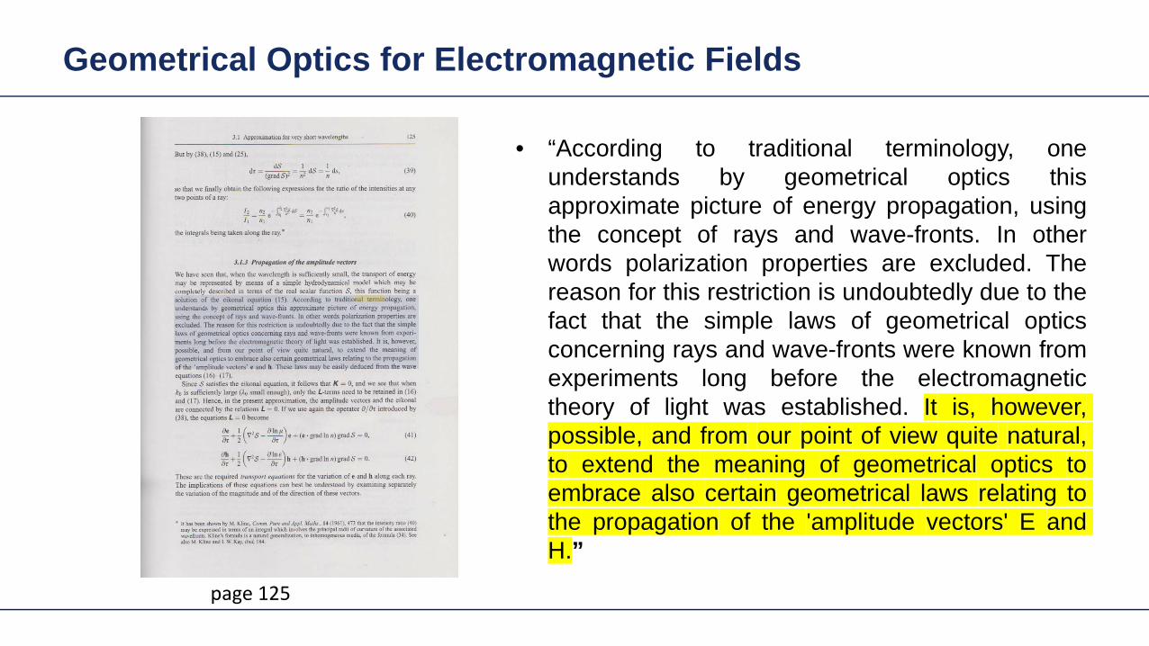
Geometrical Optics for Electromagnetic Fields
bull ldquoAccording to traditional terminology oneunderstands by geometrical optics thisapproximate picture of energy propagation usingthe concept of rays and wave-fronts In otherwords polarization properties are excluded Thereason for this restriction is undoubtedly due to thefact that the simple laws of geometrical opticsconcerning rays and wave-fronts were known fromexperiments long before the electromagnetictheory of light was established It is howeverpossible and from our point of view quite naturalto extend the meaning of geometrical optics toembrace also certain geometrical laws relating tothe propagation of the amplitude vectors E andHrdquo
page 125
Physical and Geometrical Optics Unified Theory
bull Geometricalray opticsminus Light is represented by mathematical
rays (with energy flux) which minus are governed by Frematrsquos principle
which is mathematically expressed by ray equation
bull Physical opticsminus Light represented by electromagnetic
fields which minus are governed by Maxwellrsquos equations
We follow Max Bornrsquos and Emil Wolfrsquos point of
view
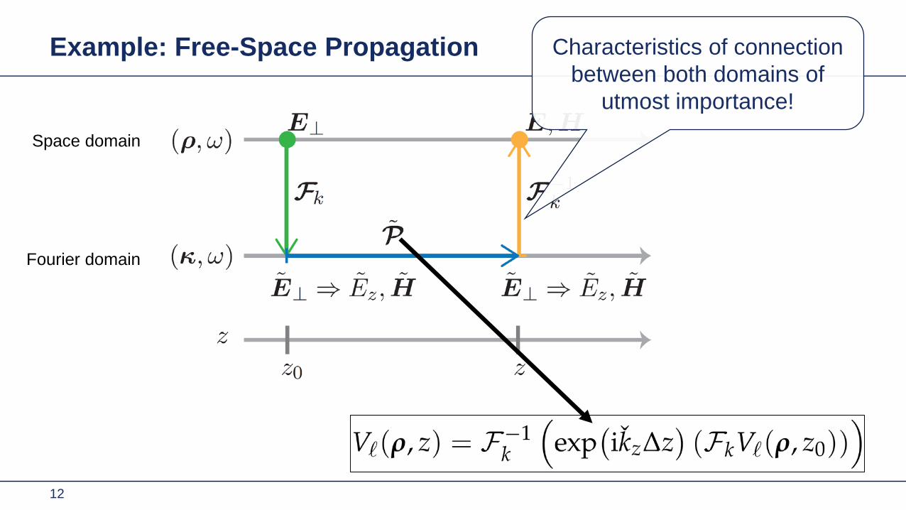
Example Free-Space Propagation
12
Space domain
Fourier domain
Characteristics of connection between both domains of
utmost importance
Example Spherical Field with Stop
13
Results of Fourier Transform
Decreasing radius of cruvature increasing NA
Results of Fourier Transform
Decreasing radius of cruvature increasing NA
Mapping between both domains geometric field zone
Fourier domain
Space domain
Example Free-Space Propagation
16
Space domain
Fourier domain
Mapping in geometric field zone expressed by geometric
Fourier transform
Physical and Geometrical Optics Unified Theory
Physical opticsbullLight represented by electromagnetic minusfields which are governed by Maxwellminus rsquos equations
Physical and Geometrical Optics Unified Theory
bull In the geometric zone of a field the geometric Fourier transform is valid for a predefined accuracy level
bull That can be interpreted as the decomposition of a field into local plane waves
bull Physical opticsminus Light represented by electromagnetic
fields which minus are governed by Maxwellrsquos equationsminus Transition between diffractivegeometric
branch fully specified and controlled by validity of geometric FT
minus Diffractive and geometric field zones
Physical and Geometrical Optics Unified Theory
bull Geometricalray opticsminus Light is represented by mathematical
rays (with energy flux) which
bull Physical opticsminus Light represented by electromagnetic
fields which minus are governed by Maxwellrsquos equationsminus Transition between diffractivegeometric
branch fully specified and controlled by validity of geometric FT
minus Diffractive and geometric field zonesField information reduced to flux (GFZ only)
Physical and Geometrical Optics Unified Theory
Physical opticsbullLight represented by electromagnetic minusfields which are governed by Maxwellminus rsquos equationsTransition between diffractivegeometric minusbranch fully specified and controlled by validity of geometric FTDiffractive and geometric field zonesminus
Physical optics in geometric zones is as fast as ray tracing (with potential to be faster)
Physical and Geometrical Optics Unified Theory
VirtualLab deals with the transitions bullbetween diffractive and geometric branch of physical optics automatically (steady development)
bull Physical opticsminus Light represented by electromagnetic
fields which minus are governed by Maxwellrsquos equationsminus Transition between diffractivegeometric
branch fully specified and controlled by validity of geometric FT
minus Diffractive and geometric field zones
Physical Optics Modeling Regional Maxwellrsquos Solver
Physical Optics Modeling Non-sequential Solver Connection
Fast physical optics approach gives deeper insight in modeling and more flexibility in design
TaskSystem Illustration
Intensity of the interference pattern
Results Ray Dot Diagram at Detector
6 mm
6 m
m
here
6 mm
Mode 1 Mode 2
6 mm
Combined
Results Field at Detector
3 mm
3 m
m
3 mm
Mode 1 Mode 2
3 mm
Combined
here
0
021
Simulation Time ~15 s
Results Field Tracing with Tilt of the Object
3 mm
3 m
m
3 mm
3deg 5deg
3 mm
10deg
here
0
045
0
021
0
016
Example of Multi-Scale Optical System
Example Wafer Inspection System
Base Grating Structure
90nm 90nm 90nm 140nm
50nm
100nm 125nm
substrate thickness = 1mmperiod size
Base Structure Analysis
Intensity Image of Grating after Polarizer in X-Direction
Intensity Image of Grating after Polarizer in Y-Direction
Simulation time few seconds
Base Grating Structure
90nm 90nm 90nm 140nm
50nm
100nm 125nm
substrate thickness = 1mmperiod size
40nm 140nm 90nm 140nm
50nm
100nm 125nm
substrate thickness = 1mmperiod size
Modified Grating Structure
Modified Structure Analysis
Intensity Image of Grating after Polarizer in X-Direction
Intensity Image of Grating after Polarizer in Y-Direction
Fast Physical Optics Freeform Surfaces
Fast Physical Optics Freeform Surfaces
50 simulations
Fast Physical Optics Freeform Surfaces
cpu time per simulation lt 1 sec
Here
Amplitude Ex(xy)
Fast simulation with low number of wavefront samples (similar to number of rays) but
noise-free detector signal

Research and Software Development Physical Optics
Jena
Applied Computational Optics Group RampD in optical modeling and design with emphasis on physical optics
Research and Software Development Physical Optics
Jena
Wyrowski Photonics Development of physical optics software VirtualLab Fusion
All examples shown in this talk were done with VirtualLab Fusion software
Research and Software Development Physical Optics
Jena
LightTransDistribution of bullVirtualLab together with distributors worldwideTechnical support bullseminars and trainingsEngineering projectsbull
A physical-optics based concept for geometric and diffractive light shaping
Diffractive and geometric branch of physical optics
Physical and Geometrical Optics Traditional Understanding
Physical and Geometrical Optics Traditional Understanding
Geometricalray opticsbullLight is represented by mathematical minusrays (with energy flux) which are governed by Frematminus rsquos principle which is mathematically expressed by ray equation
bull Physical opticsminus Light represented by electromagnetic
fields which minus are governed by Maxwellrsquos equations
Physical and Geometrical Optics Traditional Understanding
bull Geometricalray opticsminus Light is represented by mathematical
rays (with energy flux) which minus are governed by Frematrsquos principle
which is mathematically expressed by ray equation
bull Physical opticsminus Light represented by electromagnetic
fields which minus are governed by Maxwellrsquos equations
Geometrical Optics of Electromagnetic Fields
Geometrical Optics for Electromagnetic Fields
bull ldquoAccording to traditional terminology oneunderstands by geometrical optics thisapproximate picture of energy propagation usingthe concept of rays and wave-fronts In otherwords polarization properties are excluded Thereason for this restriction is undoubtedly due to thefact that the simple laws of geometrical opticsconcerning rays and wave-fronts were known fromexperiments long before the electromagnetictheory of light was established It is howeverpossible and from our point of view quite naturalto extend the meaning of geometrical optics toembrace also certain geometrical laws relating tothe propagation of the amplitude vectors E andHrdquo
page 125
Physical and Geometrical Optics Unified Theory
bull Geometricalray opticsminus Light is represented by mathematical
rays (with energy flux) which minus are governed by Frematrsquos principle
which is mathematically expressed by ray equation
bull Physical opticsminus Light represented by electromagnetic
fields which minus are governed by Maxwellrsquos equations
We follow Max Bornrsquos and Emil Wolfrsquos point of
view
Example Free-Space Propagation
12
Space domain
Fourier domain
Characteristics of connection between both domains of
utmost importance
Example Spherical Field with Stop
13
Results of Fourier Transform
Decreasing radius of cruvature increasing NA
Results of Fourier Transform
Decreasing radius of cruvature increasing NA
Mapping between both domains geometric field zone
Fourier domain
Space domain
Example Free-Space Propagation
16
Space domain
Fourier domain
Mapping in geometric field zone expressed by geometric
Fourier transform
Physical and Geometrical Optics Unified Theory
Physical opticsbullLight represented by electromagnetic minusfields which are governed by Maxwellminus rsquos equations
Physical and Geometrical Optics Unified Theory
bull In the geometric zone of a field the geometric Fourier transform is valid for a predefined accuracy level
bull That can be interpreted as the decomposition of a field into local plane waves
bull Physical opticsminus Light represented by electromagnetic
fields which minus are governed by Maxwellrsquos equationsminus Transition between diffractivegeometric
branch fully specified and controlled by validity of geometric FT
minus Diffractive and geometric field zones
Physical and Geometrical Optics Unified Theory
bull Geometricalray opticsminus Light is represented by mathematical
rays (with energy flux) which
bull Physical opticsminus Light represented by electromagnetic
fields which minus are governed by Maxwellrsquos equationsminus Transition between diffractivegeometric
branch fully specified and controlled by validity of geometric FT
minus Diffractive and geometric field zonesField information reduced to flux (GFZ only)
Physical and Geometrical Optics Unified Theory
Physical opticsbullLight represented by electromagnetic minusfields which are governed by Maxwellminus rsquos equationsTransition between diffractivegeometric minusbranch fully specified and controlled by validity of geometric FTDiffractive and geometric field zonesminus
Physical optics in geometric zones is as fast as ray tracing (with potential to be faster)
Physical and Geometrical Optics Unified Theory
VirtualLab deals with the transitions bullbetween diffractive and geometric branch of physical optics automatically (steady development)
bull Physical opticsminus Light represented by electromagnetic
fields which minus are governed by Maxwellrsquos equationsminus Transition between diffractivegeometric
branch fully specified and controlled by validity of geometric FT
minus Diffractive and geometric field zones
Physical Optics Modeling Regional Maxwellrsquos Solver
Physical Optics Modeling Non-sequential Solver Connection
Fast physical optics approach gives deeper insight in modeling and more flexibility in design
TaskSystem Illustration
Intensity of the interference pattern
Results Ray Dot Diagram at Detector
6 mm
6 m
m
here
6 mm
Mode 1 Mode 2
6 mm
Combined
Results Field at Detector
3 mm
3 m
m
3 mm
Mode 1 Mode 2
3 mm
Combined
here
0
021
Simulation Time ~15 s
Results Field Tracing with Tilt of the Object
3 mm
3 m
m
3 mm
3deg 5deg
3 mm
10deg
here
0
045
0
021
0
016
Example of Multi-Scale Optical System
Example Wafer Inspection System
Base Grating Structure
90nm 90nm 90nm 140nm
50nm
100nm 125nm
substrate thickness = 1mmperiod size
Base Structure Analysis
Intensity Image of Grating after Polarizer in X-Direction
Intensity Image of Grating after Polarizer in Y-Direction
Simulation time few seconds
Base Grating Structure
90nm 90nm 90nm 140nm
50nm
100nm 125nm
substrate thickness = 1mmperiod size
40nm 140nm 90nm 140nm
50nm
100nm 125nm
substrate thickness = 1mmperiod size
Modified Grating Structure
Modified Structure Analysis
Intensity Image of Grating after Polarizer in X-Direction
Intensity Image of Grating after Polarizer in Y-Direction
Fast Physical Optics Freeform Surfaces
Fast Physical Optics Freeform Surfaces
50 simulations
Fast Physical Optics Freeform Surfaces
cpu time per simulation lt 1 sec
Here
Amplitude Ex(xy)
Fast simulation with low number of wavefront samples (similar to number of rays) but
noise-free detector signal

Research and Software Development Physical Optics
Jena
LightTransDistribution of bullVirtualLab together with distributors worldwideTechnical support bullseminars and trainingsEngineering projectsbull
A physical-optics based concept for geometric and diffractive light shaping
Diffractive and geometric branch of physical optics
Physical and Geometrical Optics Traditional Understanding
Physical and Geometrical Optics Traditional Understanding
Geometricalray opticsbullLight is represented by mathematical minusrays (with energy flux) which are governed by Frematminus rsquos principle which is mathematically expressed by ray equation
bull Physical opticsminus Light represented by electromagnetic
fields which minus are governed by Maxwellrsquos equations
Physical and Geometrical Optics Traditional Understanding
bull Geometricalray opticsminus Light is represented by mathematical
rays (with energy flux) which minus are governed by Frematrsquos principle
which is mathematically expressed by ray equation
bull Physical opticsminus Light represented by electromagnetic
fields which minus are governed by Maxwellrsquos equations
Geometrical Optics of Electromagnetic Fields
Geometrical Optics for Electromagnetic Fields
bull ldquoAccording to traditional terminology oneunderstands by geometrical optics thisapproximate picture of energy propagation usingthe concept of rays and wave-fronts In otherwords polarization properties are excluded Thereason for this restriction is undoubtedly due to thefact that the simple laws of geometrical opticsconcerning rays and wave-fronts were known fromexperiments long before the electromagnetictheory of light was established It is howeverpossible and from our point of view quite naturalto extend the meaning of geometrical optics toembrace also certain geometrical laws relating tothe propagation of the amplitude vectors E andHrdquo
page 125
Physical and Geometrical Optics Unified Theory
bull Geometricalray opticsminus Light is represented by mathematical
rays (with energy flux) which minus are governed by Frematrsquos principle
which is mathematically expressed by ray equation
bull Physical opticsminus Light represented by electromagnetic
fields which minus are governed by Maxwellrsquos equations
We follow Max Bornrsquos and Emil Wolfrsquos point of
view
Example Free-Space Propagation
12
Space domain
Fourier domain
Characteristics of connection between both domains of
utmost importance
Example Spherical Field with Stop
13
Results of Fourier Transform
Decreasing radius of cruvature increasing NA
Results of Fourier Transform
Decreasing radius of cruvature increasing NA
Mapping between both domains geometric field zone
Fourier domain
Space domain
Example Free-Space Propagation
16
Space domain
Fourier domain
Mapping in geometric field zone expressed by geometric
Fourier transform
Physical and Geometrical Optics Unified Theory
Physical opticsbullLight represented by electromagnetic minusfields which are governed by Maxwellminus rsquos equations
Physical and Geometrical Optics Unified Theory
bull In the geometric zone of a field the geometric Fourier transform is valid for a predefined accuracy level
bull That can be interpreted as the decomposition of a field into local plane waves
bull Physical opticsminus Light represented by electromagnetic
fields which minus are governed by Maxwellrsquos equationsminus Transition between diffractivegeometric
branch fully specified and controlled by validity of geometric FT
minus Diffractive and geometric field zones
Physical and Geometrical Optics Unified Theory
bull Geometricalray opticsminus Light is represented by mathematical
rays (with energy flux) which
bull Physical opticsminus Light represented by electromagnetic
fields which minus are governed by Maxwellrsquos equationsminus Transition between diffractivegeometric
branch fully specified and controlled by validity of geometric FT
minus Diffractive and geometric field zonesField information reduced to flux (GFZ only)
Physical and Geometrical Optics Unified Theory
Physical opticsbullLight represented by electromagnetic minusfields which are governed by Maxwellminus rsquos equationsTransition between diffractivegeometric minusbranch fully specified and controlled by validity of geometric FTDiffractive and geometric field zonesminus
Physical optics in geometric zones is as fast as ray tracing (with potential to be faster)
Physical and Geometrical Optics Unified Theory
VirtualLab deals with the transitions bullbetween diffractive and geometric branch of physical optics automatically (steady development)
bull Physical opticsminus Light represented by electromagnetic
fields which minus are governed by Maxwellrsquos equationsminus Transition between diffractivegeometric
branch fully specified and controlled by validity of geometric FT
minus Diffractive and geometric field zones
Physical Optics Modeling Regional Maxwellrsquos Solver
Physical Optics Modeling Non-sequential Solver Connection
Fast physical optics approach gives deeper insight in modeling and more flexibility in design
TaskSystem Illustration
Intensity of the interference pattern
Results Ray Dot Diagram at Detector
6 mm
6 m
m
here
6 mm
Mode 1 Mode 2
6 mm
Combined
Results Field at Detector
3 mm
3 m
m
3 mm
Mode 1 Mode 2
3 mm
Combined
here
0
021
Simulation Time ~15 s
Results Field Tracing with Tilt of the Object
3 mm
3 m
m
3 mm
3deg 5deg
3 mm
10deg
here
0
045
0
021
0
016
Example of Multi-Scale Optical System
Example Wafer Inspection System
Base Grating Structure
90nm 90nm 90nm 140nm
50nm
100nm 125nm
substrate thickness = 1mmperiod size
Base Structure Analysis
Intensity Image of Grating after Polarizer in X-Direction
Intensity Image of Grating after Polarizer in Y-Direction
Simulation time few seconds
Base Grating Structure
90nm 90nm 90nm 140nm
50nm
100nm 125nm
substrate thickness = 1mmperiod size
40nm 140nm 90nm 140nm
50nm
100nm 125nm
substrate thickness = 1mmperiod size
Modified Grating Structure
Modified Structure Analysis
Intensity Image of Grating after Polarizer in X-Direction
Intensity Image of Grating after Polarizer in Y-Direction
Fast Physical Optics Freeform Surfaces
Fast Physical Optics Freeform Surfaces
50 simulations
Fast Physical Optics Freeform Surfaces
cpu time per simulation lt 1 sec
Here
Amplitude Ex(xy)
Fast simulation with low number of wavefront samples (similar to number of rays) but
noise-free detector signal

Physical and Geometrical Optics Traditional Understanding
Physical and Geometrical Optics Traditional Understanding
Geometricalray opticsbullLight is represented by mathematical minusrays (with energy flux) which are governed by Frematminus rsquos principle which is mathematically expressed by ray equation
bull Physical opticsminus Light represented by electromagnetic
fields which minus are governed by Maxwellrsquos equations
Physical and Geometrical Optics Traditional Understanding
bull Geometricalray opticsminus Light is represented by mathematical
rays (with energy flux) which minus are governed by Frematrsquos principle
which is mathematically expressed by ray equation
bull Physical opticsminus Light represented by electromagnetic
fields which minus are governed by Maxwellrsquos equations
Geometrical Optics of Electromagnetic Fields
Geometrical Optics for Electromagnetic Fields
bull ldquoAccording to traditional terminology oneunderstands by geometrical optics thisapproximate picture of energy propagation usingthe concept of rays and wave-fronts In otherwords polarization properties are excluded Thereason for this restriction is undoubtedly due to thefact that the simple laws of geometrical opticsconcerning rays and wave-fronts were known fromexperiments long before the electromagnetictheory of light was established It is howeverpossible and from our point of view quite naturalto extend the meaning of geometrical optics toembrace also certain geometrical laws relating tothe propagation of the amplitude vectors E andHrdquo
page 125
Physical and Geometrical Optics Unified Theory
bull Geometricalray opticsminus Light is represented by mathematical
rays (with energy flux) which minus are governed by Frematrsquos principle
which is mathematically expressed by ray equation
bull Physical opticsminus Light represented by electromagnetic
fields which minus are governed by Maxwellrsquos equations
We follow Max Bornrsquos and Emil Wolfrsquos point of
view
Example Free-Space Propagation
12
Space domain
Fourier domain
Characteristics of connection between both domains of
utmost importance
Example Spherical Field with Stop
13
Results of Fourier Transform
Decreasing radius of cruvature increasing NA
Results of Fourier Transform
Decreasing radius of cruvature increasing NA
Mapping between both domains geometric field zone
Fourier domain
Space domain
Example Free-Space Propagation
16
Space domain
Fourier domain
Mapping in geometric field zone expressed by geometric
Fourier transform
Physical and Geometrical Optics Unified Theory
Physical opticsbullLight represented by electromagnetic minusfields which are governed by Maxwellminus rsquos equations
Physical and Geometrical Optics Unified Theory
bull In the geometric zone of a field the geometric Fourier transform is valid for a predefined accuracy level
bull That can be interpreted as the decomposition of a field into local plane waves
bull Physical opticsminus Light represented by electromagnetic
fields which minus are governed by Maxwellrsquos equationsminus Transition between diffractivegeometric
branch fully specified and controlled by validity of geometric FT
minus Diffractive and geometric field zones
Physical and Geometrical Optics Unified Theory
bull Geometricalray opticsminus Light is represented by mathematical
rays (with energy flux) which
bull Physical opticsminus Light represented by electromagnetic
fields which minus are governed by Maxwellrsquos equationsminus Transition between diffractivegeometric
branch fully specified and controlled by validity of geometric FT
minus Diffractive and geometric field zonesField information reduced to flux (GFZ only)
Physical and Geometrical Optics Unified Theory
Physical opticsbullLight represented by electromagnetic minusfields which are governed by Maxwellminus rsquos equationsTransition between diffractivegeometric minusbranch fully specified and controlled by validity of geometric FTDiffractive and geometric field zonesminus
Physical optics in geometric zones is as fast as ray tracing (with potential to be faster)
Physical and Geometrical Optics Unified Theory
VirtualLab deals with the transitions bullbetween diffractive and geometric branch of physical optics automatically (steady development)
bull Physical opticsminus Light represented by electromagnetic
fields which minus are governed by Maxwellrsquos equationsminus Transition between diffractivegeometric
branch fully specified and controlled by validity of geometric FT
minus Diffractive and geometric field zones
Physical Optics Modeling Regional Maxwellrsquos Solver
Physical Optics Modeling Non-sequential Solver Connection
Fast physical optics approach gives deeper insight in modeling and more flexibility in design
TaskSystem Illustration
Intensity of the interference pattern
Results Ray Dot Diagram at Detector
6 mm
6 m
m
here
6 mm
Mode 1 Mode 2
6 mm
Combined
Results Field at Detector
3 mm
3 m
m
3 mm
Mode 1 Mode 2
3 mm
Combined
here
0
021
Simulation Time ~15 s
Results Field Tracing with Tilt of the Object
3 mm
3 m
m
3 mm
3deg 5deg
3 mm
10deg
here
0
045
0
021
0
016
Example of Multi-Scale Optical System
Example Wafer Inspection System
Base Grating Structure
90nm 90nm 90nm 140nm
50nm
100nm 125nm
substrate thickness = 1mmperiod size
Base Structure Analysis
Intensity Image of Grating after Polarizer in X-Direction
Intensity Image of Grating after Polarizer in Y-Direction
Simulation time few seconds
Base Grating Structure
90nm 90nm 90nm 140nm
50nm
100nm 125nm
substrate thickness = 1mmperiod size
40nm 140nm 90nm 140nm
50nm
100nm 125nm
substrate thickness = 1mmperiod size
Modified Grating Structure
Modified Structure Analysis
Intensity Image of Grating after Polarizer in X-Direction
Intensity Image of Grating after Polarizer in Y-Direction
Fast Physical Optics Freeform Surfaces
Fast Physical Optics Freeform Surfaces
50 simulations
Fast Physical Optics Freeform Surfaces
cpu time per simulation lt 1 sec
Here
Amplitude Ex(xy)
Fast simulation with low number of wavefront samples (similar to number of rays) but
noise-free detector signal

Physical and Geometrical Optics Traditional Understanding
bull Geometricalray opticsminus Light is represented by mathematical
rays (with energy flux) which minus are governed by Frematrsquos principle
which is mathematically expressed by ray equation
bull Physical opticsminus Light represented by electromagnetic
fields which minus are governed by Maxwellrsquos equations
Geometrical Optics of Electromagnetic Fields
Geometrical Optics for Electromagnetic Fields
bull ldquoAccording to traditional terminology oneunderstands by geometrical optics thisapproximate picture of energy propagation usingthe concept of rays and wave-fronts In otherwords polarization properties are excluded Thereason for this restriction is undoubtedly due to thefact that the simple laws of geometrical opticsconcerning rays and wave-fronts were known fromexperiments long before the electromagnetictheory of light was established It is howeverpossible and from our point of view quite naturalto extend the meaning of geometrical optics toembrace also certain geometrical laws relating tothe propagation of the amplitude vectors E andHrdquo
page 125
Physical and Geometrical Optics Unified Theory
bull Geometricalray opticsminus Light is represented by mathematical
rays (with energy flux) which minus are governed by Frematrsquos principle
which is mathematically expressed by ray equation
bull Physical opticsminus Light represented by electromagnetic
fields which minus are governed by Maxwellrsquos equations
We follow Max Bornrsquos and Emil Wolfrsquos point of
view
Example Free-Space Propagation
12
Space domain
Fourier domain
Characteristics of connection between both domains of
utmost importance
Example Spherical Field with Stop
13
Results of Fourier Transform
Decreasing radius of cruvature increasing NA
Results of Fourier Transform
Decreasing radius of cruvature increasing NA
Mapping between both domains geometric field zone
Fourier domain
Space domain
Example Free-Space Propagation
16
Space domain
Fourier domain
Mapping in geometric field zone expressed by geometric
Fourier transform
Physical and Geometrical Optics Unified Theory
Physical opticsbullLight represented by electromagnetic minusfields which are governed by Maxwellminus rsquos equations
Physical and Geometrical Optics Unified Theory
bull In the geometric zone of a field the geometric Fourier transform is valid for a predefined accuracy level
bull That can be interpreted as the decomposition of a field into local plane waves
bull Physical opticsminus Light represented by electromagnetic
fields which minus are governed by Maxwellrsquos equationsminus Transition between diffractivegeometric
branch fully specified and controlled by validity of geometric FT
minus Diffractive and geometric field zones
Physical and Geometrical Optics Unified Theory
bull Geometricalray opticsminus Light is represented by mathematical
rays (with energy flux) which
bull Physical opticsminus Light represented by electromagnetic
fields which minus are governed by Maxwellrsquos equationsminus Transition between diffractivegeometric
branch fully specified and controlled by validity of geometric FT
minus Diffractive and geometric field zonesField information reduced to flux (GFZ only)
Physical and Geometrical Optics Unified Theory
Physical opticsbullLight represented by electromagnetic minusfields which are governed by Maxwellminus rsquos equationsTransition between diffractivegeometric minusbranch fully specified and controlled by validity of geometric FTDiffractive and geometric field zonesminus
Physical optics in geometric zones is as fast as ray tracing (with potential to be faster)
Physical and Geometrical Optics Unified Theory
VirtualLab deals with the transitions bullbetween diffractive and geometric branch of physical optics automatically (steady development)
bull Physical opticsminus Light represented by electromagnetic
fields which minus are governed by Maxwellrsquos equationsminus Transition between diffractivegeometric
branch fully specified and controlled by validity of geometric FT
minus Diffractive and geometric field zones
Physical Optics Modeling Regional Maxwellrsquos Solver
Physical Optics Modeling Non-sequential Solver Connection
Fast physical optics approach gives deeper insight in modeling and more flexibility in design
TaskSystem Illustration
Intensity of the interference pattern
Results Ray Dot Diagram at Detector
6 mm
6 m
m
here
6 mm
Mode 1 Mode 2
6 mm
Combined
Results Field at Detector
3 mm
3 m
m
3 mm
Mode 1 Mode 2
3 mm
Combined
here
0
021
Simulation Time ~15 s
Results Field Tracing with Tilt of the Object
3 mm
3 m
m
3 mm
3deg 5deg
3 mm
10deg
here
0
045
0
021
0
016
Example of Multi-Scale Optical System
Example Wafer Inspection System
Base Grating Structure
90nm 90nm 90nm 140nm
50nm
100nm 125nm
substrate thickness = 1mmperiod size
Base Structure Analysis
Intensity Image of Grating after Polarizer in X-Direction
Intensity Image of Grating after Polarizer in Y-Direction
Simulation time few seconds
Base Grating Structure
90nm 90nm 90nm 140nm
50nm
100nm 125nm
substrate thickness = 1mmperiod size
40nm 140nm 90nm 140nm
50nm
100nm 125nm
substrate thickness = 1mmperiod size
Modified Grating Structure
Modified Structure Analysis
Intensity Image of Grating after Polarizer in X-Direction
Intensity Image of Grating after Polarizer in Y-Direction
Fast Physical Optics Freeform Surfaces
Fast Physical Optics Freeform Surfaces
50 simulations
Fast Physical Optics Freeform Surfaces
cpu time per simulation lt 1 sec
Here
Amplitude Ex(xy)
Fast simulation with low number of wavefront samples (similar to number of rays) but
noise-free detector signal

Physical and Geometrical Optics Unified Theory
bull Geometricalray opticsminus Light is represented by mathematical
rays (with energy flux) which minus are governed by Frematrsquos principle
which is mathematically expressed by ray equation
bull Physical opticsminus Light represented by electromagnetic
fields which minus are governed by Maxwellrsquos equations
We follow Max Bornrsquos and Emil Wolfrsquos point of
view
Example Free-Space Propagation
12
Space domain
Fourier domain
Characteristics of connection between both domains of
utmost importance
Example Spherical Field with Stop
13
Results of Fourier Transform
Decreasing radius of cruvature increasing NA
Results of Fourier Transform
Decreasing radius of cruvature increasing NA
Mapping between both domains geometric field zone
Fourier domain
Space domain
Example Free-Space Propagation
16
Space domain
Fourier domain
Mapping in geometric field zone expressed by geometric
Fourier transform
Physical and Geometrical Optics Unified Theory
Physical opticsbullLight represented by electromagnetic minusfields which are governed by Maxwellminus rsquos equations
Physical and Geometrical Optics Unified Theory
bull In the geometric zone of a field the geometric Fourier transform is valid for a predefined accuracy level
bull That can be interpreted as the decomposition of a field into local plane waves
bull Physical opticsminus Light represented by electromagnetic
fields which minus are governed by Maxwellrsquos equationsminus Transition between diffractivegeometric
branch fully specified and controlled by validity of geometric FT
minus Diffractive and geometric field zones
Physical and Geometrical Optics Unified Theory
bull Geometricalray opticsminus Light is represented by mathematical
rays (with energy flux) which
bull Physical opticsminus Light represented by electromagnetic
fields which minus are governed by Maxwellrsquos equationsminus Transition between diffractivegeometric
branch fully specified and controlled by validity of geometric FT
minus Diffractive and geometric field zonesField information reduced to flux (GFZ only)
Physical and Geometrical Optics Unified Theory
Physical opticsbullLight represented by electromagnetic minusfields which are governed by Maxwellminus rsquos equationsTransition between diffractivegeometric minusbranch fully specified and controlled by validity of geometric FTDiffractive and geometric field zonesminus
Physical optics in geometric zones is as fast as ray tracing (with potential to be faster)
Physical and Geometrical Optics Unified Theory
VirtualLab deals with the transitions bullbetween diffractive and geometric branch of physical optics automatically (steady development)
bull Physical opticsminus Light represented by electromagnetic
fields which minus are governed by Maxwellrsquos equationsminus Transition between diffractivegeometric
branch fully specified and controlled by validity of geometric FT
minus Diffractive and geometric field zones
Physical Optics Modeling Regional Maxwellrsquos Solver
Physical Optics Modeling Non-sequential Solver Connection
Fast physical optics approach gives deeper insight in modeling and more flexibility in design
TaskSystem Illustration
Intensity of the interference pattern
Results Ray Dot Diagram at Detector
6 mm
6 m
m
here
6 mm
Mode 1 Mode 2
6 mm
Combined
Results Field at Detector
3 mm
3 m
m
3 mm
Mode 1 Mode 2
3 mm
Combined
here
0
021
Simulation Time ~15 s
Results Field Tracing with Tilt of the Object
3 mm
3 m
m
3 mm
3deg 5deg
3 mm
10deg
here
0
045
0
021
0
016
Example of Multi-Scale Optical System
Example Wafer Inspection System
Base Grating Structure
90nm 90nm 90nm 140nm
50nm
100nm 125nm
substrate thickness = 1mmperiod size
Base Structure Analysis
Intensity Image of Grating after Polarizer in X-Direction
Intensity Image of Grating after Polarizer in Y-Direction
Simulation time few seconds
Base Grating Structure
90nm 90nm 90nm 140nm
50nm
100nm 125nm
substrate thickness = 1mmperiod size
40nm 140nm 90nm 140nm
50nm
100nm 125nm
substrate thickness = 1mmperiod size
Modified Grating Structure
Modified Structure Analysis
Intensity Image of Grating after Polarizer in X-Direction
Intensity Image of Grating after Polarizer in Y-Direction
Fast Physical Optics Freeform Surfaces
Fast Physical Optics Freeform Surfaces
50 simulations
Fast Physical Optics Freeform Surfaces
cpu time per simulation lt 1 sec
Here
Amplitude Ex(xy)
Fast simulation with low number of wavefront samples (similar to number of rays) but
noise-free detector signal
Example Free-Space Propagation
12
Space domain
Fourier domain
Characteristics of connection between both domains of
utmost importance
Example Spherical Field with Stop
13
Results of Fourier Transform
Decreasing radius of cruvature increasing NA
Results of Fourier Transform
Decreasing radius of cruvature increasing NA
Mapping between both domains geometric field zone
Fourier domain
Space domain
Example Free-Space Propagation
16
Space domain
Fourier domain
Mapping in geometric field zone expressed by geometric
Fourier transform
Physical and Geometrical Optics Unified Theory
Physical opticsbullLight represented by electromagnetic minusfields which are governed by Maxwellminus rsquos equations
Physical and Geometrical Optics Unified Theory
bull In the geometric zone of a field the geometric Fourier transform is valid for a predefined accuracy level
bull That can be interpreted as the decomposition of a field into local plane waves
bull Physical opticsminus Light represented by electromagnetic
fields which minus are governed by Maxwellrsquos equationsminus Transition between diffractivegeometric
branch fully specified and controlled by validity of geometric FT
minus Diffractive and geometric field zones
Physical and Geometrical Optics Unified Theory
bull Geometricalray opticsminus Light is represented by mathematical
rays (with energy flux) which
bull Physical opticsminus Light represented by electromagnetic
fields which minus are governed by Maxwellrsquos equationsminus Transition between diffractivegeometric
branch fully specified and controlled by validity of geometric FT
minus Diffractive and geometric field zonesField information reduced to flux (GFZ only)
Physical and Geometrical Optics Unified Theory
Physical opticsbullLight represented by electromagnetic minusfields which are governed by Maxwellminus rsquos equationsTransition between diffractivegeometric minusbranch fully specified and controlled by validity of geometric FTDiffractive and geometric field zonesminus
Physical optics in geometric zones is as fast as ray tracing (with potential to be faster)
Physical and Geometrical Optics Unified Theory
VirtualLab deals with the transitions bullbetween diffractive and geometric branch of physical optics automatically (steady development)
bull Physical opticsminus Light represented by electromagnetic
fields which minus are governed by Maxwellrsquos equationsminus Transition between diffractivegeometric
branch fully specified and controlled by validity of geometric FT
minus Diffractive and geometric field zones
Physical Optics Modeling Regional Maxwellrsquos Solver
Physical Optics Modeling Non-sequential Solver Connection
Fast physical optics approach gives deeper insight in modeling and more flexibility in design
TaskSystem Illustration
Intensity of the interference pattern
Results Ray Dot Diagram at Detector
6 mm
6 m
m
here
6 mm
Mode 1 Mode 2
6 mm
Combined
Results Field at Detector
3 mm
3 m
m
3 mm
Mode 1 Mode 2
3 mm
Combined
here
0
021
Simulation Time ~15 s
Results Field Tracing with Tilt of the Object
3 mm
3 m
m
3 mm
3deg 5deg
3 mm
10deg
here
0
045
0
021
0
016
Example of Multi-Scale Optical System
Example Wafer Inspection System
Base Grating Structure
90nm 90nm 90nm 140nm
50nm
100nm 125nm
substrate thickness = 1mmperiod size
Base Structure Analysis
Intensity Image of Grating after Polarizer in X-Direction
Intensity Image of Grating after Polarizer in Y-Direction
Simulation time few seconds
Base Grating Structure
90nm 90nm 90nm 140nm
50nm
100nm 125nm
substrate thickness = 1mmperiod size
40nm 140nm 90nm 140nm
50nm
100nm 125nm
substrate thickness = 1mmperiod size
Modified Grating Structure
Modified Structure Analysis
Intensity Image of Grating after Polarizer in X-Direction
Intensity Image of Grating after Polarizer in Y-Direction
Fast Physical Optics Freeform Surfaces
Fast Physical Optics Freeform Surfaces
50 simulations
Fast Physical Optics Freeform Surfaces
cpu time per simulation lt 1 sec
Here
Amplitude Ex(xy)
Fast simulation with low number of wavefront samples (similar to number of rays) but
noise-free detector signal
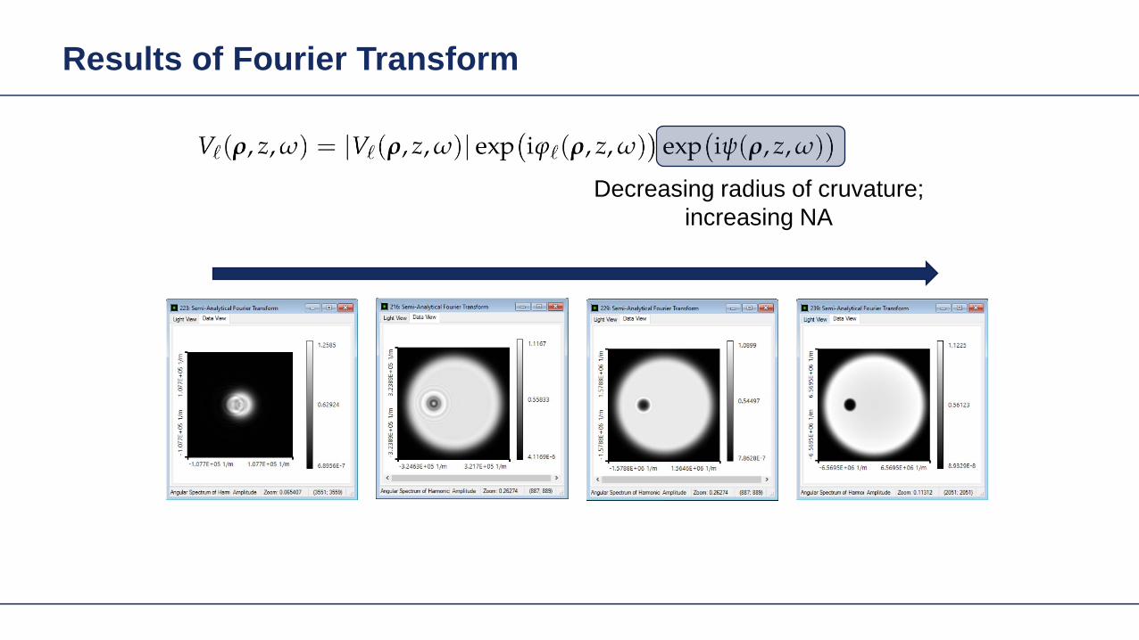
Results of Fourier Transform
Decreasing radius of cruvature increasing NA
Results of Fourier Transform
Decreasing radius of cruvature increasing NA
Mapping between both domains geometric field zone
Fourier domain
Space domain
Example Free-Space Propagation
16
Space domain
Fourier domain
Mapping in geometric field zone expressed by geometric
Fourier transform
Physical and Geometrical Optics Unified Theory
Physical opticsbullLight represented by electromagnetic minusfields which are governed by Maxwellminus rsquos equations
Physical and Geometrical Optics Unified Theory
bull In the geometric zone of a field the geometric Fourier transform is valid for a predefined accuracy level
bull That can be interpreted as the decomposition of a field into local plane waves
bull Physical opticsminus Light represented by electromagnetic
fields which minus are governed by Maxwellrsquos equationsminus Transition between diffractivegeometric
branch fully specified and controlled by validity of geometric FT
minus Diffractive and geometric field zones
Physical and Geometrical Optics Unified Theory
bull Geometricalray opticsminus Light is represented by mathematical
rays (with energy flux) which
bull Physical opticsminus Light represented by electromagnetic
fields which minus are governed by Maxwellrsquos equationsminus Transition between diffractivegeometric
branch fully specified and controlled by validity of geometric FT
minus Diffractive and geometric field zonesField information reduced to flux (GFZ only)
Physical and Geometrical Optics Unified Theory
Physical opticsbullLight represented by electromagnetic minusfields which are governed by Maxwellminus rsquos equationsTransition between diffractivegeometric minusbranch fully specified and controlled by validity of geometric FTDiffractive and geometric field zonesminus
Physical optics in geometric zones is as fast as ray tracing (with potential to be faster)
Physical and Geometrical Optics Unified Theory
VirtualLab deals with the transitions bullbetween diffractive and geometric branch of physical optics automatically (steady development)
bull Physical opticsminus Light represented by electromagnetic
fields which minus are governed by Maxwellrsquos equationsminus Transition between diffractivegeometric
branch fully specified and controlled by validity of geometric FT
minus Diffractive and geometric field zones
Physical Optics Modeling Regional Maxwellrsquos Solver
Physical Optics Modeling Non-sequential Solver Connection
Fast physical optics approach gives deeper insight in modeling and more flexibility in design
TaskSystem Illustration
Intensity of the interference pattern
Results Ray Dot Diagram at Detector
6 mm
6 m
m
here
6 mm
Mode 1 Mode 2
6 mm
Combined
Results Field at Detector
3 mm
3 m
m
3 mm
Mode 1 Mode 2
3 mm
Combined
here
0
021
Simulation Time ~15 s
Results Field Tracing with Tilt of the Object
3 mm
3 m
m
3 mm
3deg 5deg
3 mm
10deg
here
0
045
0
021
0
016
Example of Multi-Scale Optical System
Example Wafer Inspection System
Base Grating Structure
90nm 90nm 90nm 140nm
50nm
100nm 125nm
substrate thickness = 1mmperiod size
Base Structure Analysis
Intensity Image of Grating after Polarizer in X-Direction
Intensity Image of Grating after Polarizer in Y-Direction
Simulation time few seconds
Base Grating Structure
90nm 90nm 90nm 140nm
50nm
100nm 125nm
substrate thickness = 1mmperiod size
40nm 140nm 90nm 140nm
50nm
100nm 125nm
substrate thickness = 1mmperiod size
Modified Grating Structure
Modified Structure Analysis
Intensity Image of Grating after Polarizer in X-Direction
Intensity Image of Grating after Polarizer in Y-Direction
Fast Physical Optics Freeform Surfaces
Fast Physical Optics Freeform Surfaces
50 simulations
Fast Physical Optics Freeform Surfaces
cpu time per simulation lt 1 sec
Here
Amplitude Ex(xy)
Fast simulation with low number of wavefront samples (similar to number of rays) but
noise-free detector signal
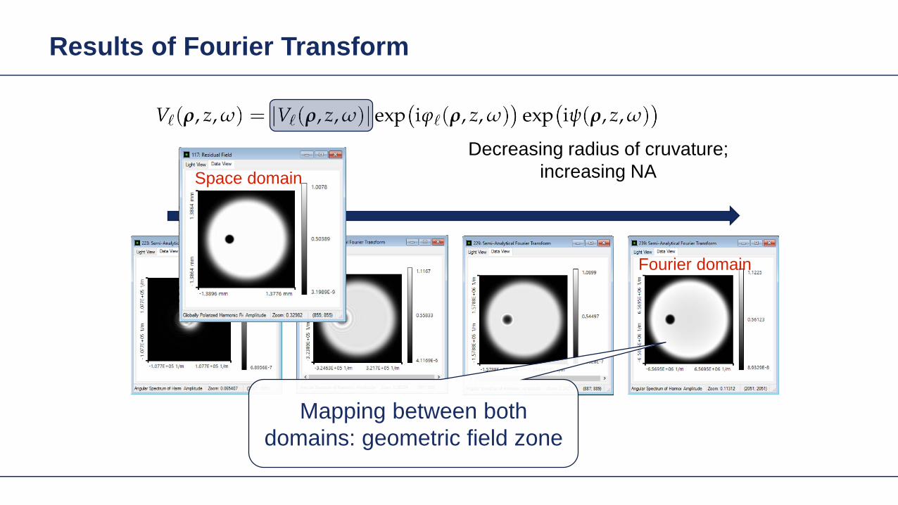
Results of Fourier Transform
Decreasing radius of cruvature increasing NA
Mapping between both domains geometric field zone
Fourier domain
Space domain
Example Free-Space Propagation
16
Space domain
Fourier domain
Mapping in geometric field zone expressed by geometric
Fourier transform
Physical and Geometrical Optics Unified Theory
Physical opticsbullLight represented by electromagnetic minusfields which are governed by Maxwellminus rsquos equations
Physical and Geometrical Optics Unified Theory
bull In the geometric zone of a field the geometric Fourier transform is valid for a predefined accuracy level
bull That can be interpreted as the decomposition of a field into local plane waves
bull Physical opticsminus Light represented by electromagnetic
fields which minus are governed by Maxwellrsquos equationsminus Transition between diffractivegeometric
branch fully specified and controlled by validity of geometric FT
minus Diffractive and geometric field zones
Physical and Geometrical Optics Unified Theory
bull Geometricalray opticsminus Light is represented by mathematical
rays (with energy flux) which
bull Physical opticsminus Light represented by electromagnetic
fields which minus are governed by Maxwellrsquos equationsminus Transition between diffractivegeometric
branch fully specified and controlled by validity of geometric FT
minus Diffractive and geometric field zonesField information reduced to flux (GFZ only)
Physical and Geometrical Optics Unified Theory
Physical opticsbullLight represented by electromagnetic minusfields which are governed by Maxwellminus rsquos equationsTransition between diffractivegeometric minusbranch fully specified and controlled by validity of geometric FTDiffractive and geometric field zonesminus
Physical optics in geometric zones is as fast as ray tracing (with potential to be faster)
Physical and Geometrical Optics Unified Theory
VirtualLab deals with the transitions bullbetween diffractive and geometric branch of physical optics automatically (steady development)
bull Physical opticsminus Light represented by electromagnetic
fields which minus are governed by Maxwellrsquos equationsminus Transition between diffractivegeometric
branch fully specified and controlled by validity of geometric FT
minus Diffractive and geometric field zones
Physical Optics Modeling Regional Maxwellrsquos Solver
Physical Optics Modeling Non-sequential Solver Connection
Fast physical optics approach gives deeper insight in modeling and more flexibility in design
TaskSystem Illustration
Intensity of the interference pattern
Results Ray Dot Diagram at Detector
6 mm
6 m
m
here
6 mm
Mode 1 Mode 2
6 mm
Combined
Results Field at Detector
3 mm
3 m
m
3 mm
Mode 1 Mode 2
3 mm
Combined
here
0
021
Simulation Time ~15 s
Results Field Tracing with Tilt of the Object
3 mm
3 m
m
3 mm
3deg 5deg
3 mm
10deg
here
0
045
0
021
0
016
Example of Multi-Scale Optical System
Example Wafer Inspection System
Base Grating Structure
90nm 90nm 90nm 140nm
50nm
100nm 125nm
substrate thickness = 1mmperiod size
Base Structure Analysis
Intensity Image of Grating after Polarizer in X-Direction
Intensity Image of Grating after Polarizer in Y-Direction
Simulation time few seconds
Base Grating Structure
90nm 90nm 90nm 140nm
50nm
100nm 125nm
substrate thickness = 1mmperiod size
40nm 140nm 90nm 140nm
50nm
100nm 125nm
substrate thickness = 1mmperiod size
Modified Grating Structure
Modified Structure Analysis
Intensity Image of Grating after Polarizer in X-Direction
Intensity Image of Grating after Polarizer in Y-Direction
Fast Physical Optics Freeform Surfaces
Fast Physical Optics Freeform Surfaces
50 simulations
Fast Physical Optics Freeform Surfaces
cpu time per simulation lt 1 sec
Here
Amplitude Ex(xy)
Fast simulation with low number of wavefront samples (similar to number of rays) but
noise-free detector signal

Physical and Geometrical Optics Unified Theory
Physical opticsbullLight represented by electromagnetic minusfields which are governed by Maxwellminus rsquos equations
Physical and Geometrical Optics Unified Theory
bull In the geometric zone of a field the geometric Fourier transform is valid for a predefined accuracy level
bull That can be interpreted as the decomposition of a field into local plane waves
bull Physical opticsminus Light represented by electromagnetic
fields which minus are governed by Maxwellrsquos equationsminus Transition between diffractivegeometric
branch fully specified and controlled by validity of geometric FT
minus Diffractive and geometric field zones
Physical and Geometrical Optics Unified Theory
bull Geometricalray opticsminus Light is represented by mathematical
rays (with energy flux) which
bull Physical opticsminus Light represented by electromagnetic
fields which minus are governed by Maxwellrsquos equationsminus Transition between diffractivegeometric
branch fully specified and controlled by validity of geometric FT
minus Diffractive and geometric field zonesField information reduced to flux (GFZ only)
Physical and Geometrical Optics Unified Theory
Physical opticsbullLight represented by electromagnetic minusfields which are governed by Maxwellminus rsquos equationsTransition between diffractivegeometric minusbranch fully specified and controlled by validity of geometric FTDiffractive and geometric field zonesminus
Physical optics in geometric zones is as fast as ray tracing (with potential to be faster)
Physical and Geometrical Optics Unified Theory
VirtualLab deals with the transitions bullbetween diffractive and geometric branch of physical optics automatically (steady development)
bull Physical opticsminus Light represented by electromagnetic
fields which minus are governed by Maxwellrsquos equationsminus Transition between diffractivegeometric
branch fully specified and controlled by validity of geometric FT
minus Diffractive and geometric field zones
Physical Optics Modeling Regional Maxwellrsquos Solver
Physical Optics Modeling Non-sequential Solver Connection
Fast physical optics approach gives deeper insight in modeling and more flexibility in design
TaskSystem Illustration
Intensity of the interference pattern
Results Ray Dot Diagram at Detector
6 mm
6 m
m
here
6 mm
Mode 1 Mode 2
6 mm
Combined
Results Field at Detector
3 mm
3 m
m
3 mm
Mode 1 Mode 2
3 mm
Combined
here
0
021
Simulation Time ~15 s
Results Field Tracing with Tilt of the Object
3 mm
3 m
m
3 mm
3deg 5deg
3 mm
10deg
here
0
045
0
021
0
016
Example of Multi-Scale Optical System
Example Wafer Inspection System
Base Grating Structure
90nm 90nm 90nm 140nm
50nm
100nm 125nm
substrate thickness = 1mmperiod size
Base Structure Analysis
Intensity Image of Grating after Polarizer in X-Direction
Intensity Image of Grating after Polarizer in Y-Direction
Simulation time few seconds
Base Grating Structure
90nm 90nm 90nm 140nm
50nm
100nm 125nm
substrate thickness = 1mmperiod size
40nm 140nm 90nm 140nm
50nm
100nm 125nm
substrate thickness = 1mmperiod size
Modified Grating Structure
Modified Structure Analysis
Intensity Image of Grating after Polarizer in X-Direction
Intensity Image of Grating after Polarizer in Y-Direction
Fast Physical Optics Freeform Surfaces
Fast Physical Optics Freeform Surfaces
50 simulations
Fast Physical Optics Freeform Surfaces
cpu time per simulation lt 1 sec
Here
Amplitude Ex(xy)
Fast simulation with low number of wavefront samples (similar to number of rays) but
noise-free detector signal
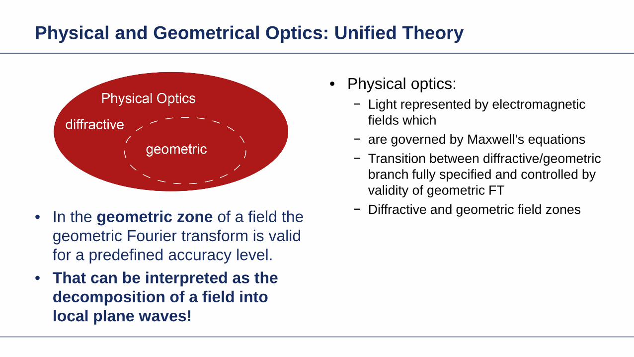
Physical and Geometrical Optics Unified Theory
bull In the geometric zone of a field the geometric Fourier transform is valid for a predefined accuracy level
bull That can be interpreted as the decomposition of a field into local plane waves
bull Physical opticsminus Light represented by electromagnetic
fields which minus are governed by Maxwellrsquos equationsminus Transition between diffractivegeometric
branch fully specified and controlled by validity of geometric FT
minus Diffractive and geometric field zones
Physical and Geometrical Optics Unified Theory
bull Geometricalray opticsminus Light is represented by mathematical
rays (with energy flux) which
bull Physical opticsminus Light represented by electromagnetic
fields which minus are governed by Maxwellrsquos equationsminus Transition between diffractivegeometric
branch fully specified and controlled by validity of geometric FT
minus Diffractive and geometric field zonesField information reduced to flux (GFZ only)
Physical and Geometrical Optics Unified Theory
Physical opticsbullLight represented by electromagnetic minusfields which are governed by Maxwellminus rsquos equationsTransition between diffractivegeometric minusbranch fully specified and controlled by validity of geometric FTDiffractive and geometric field zonesminus
Physical optics in geometric zones is as fast as ray tracing (with potential to be faster)
Physical and Geometrical Optics Unified Theory
VirtualLab deals with the transitions bullbetween diffractive and geometric branch of physical optics automatically (steady development)
bull Physical opticsminus Light represented by electromagnetic
fields which minus are governed by Maxwellrsquos equationsminus Transition between diffractivegeometric
branch fully specified and controlled by validity of geometric FT
minus Diffractive and geometric field zones
Physical Optics Modeling Regional Maxwellrsquos Solver
Physical Optics Modeling Non-sequential Solver Connection
Fast physical optics approach gives deeper insight in modeling and more flexibility in design
TaskSystem Illustration
Intensity of the interference pattern
Results Ray Dot Diagram at Detector
6 mm
6 m
m
here
6 mm
Mode 1 Mode 2
6 mm
Combined
Results Field at Detector
3 mm
3 m
m
3 mm
Mode 1 Mode 2
3 mm
Combined
here
0
021
Simulation Time ~15 s
Results Field Tracing with Tilt of the Object
3 mm
3 m
m
3 mm
3deg 5deg
3 mm
10deg
here
0
045
0
021
0
016
Example of Multi-Scale Optical System
Example Wafer Inspection System
Base Grating Structure
90nm 90nm 90nm 140nm
50nm
100nm 125nm
substrate thickness = 1mmperiod size
Base Structure Analysis
Intensity Image of Grating after Polarizer in X-Direction
Intensity Image of Grating after Polarizer in Y-Direction
Simulation time few seconds
Base Grating Structure
90nm 90nm 90nm 140nm
50nm
100nm 125nm
substrate thickness = 1mmperiod size
40nm 140nm 90nm 140nm
50nm
100nm 125nm
substrate thickness = 1mmperiod size
Modified Grating Structure
Modified Structure Analysis
Intensity Image of Grating after Polarizer in X-Direction
Intensity Image of Grating after Polarizer in Y-Direction
Fast Physical Optics Freeform Surfaces
Fast Physical Optics Freeform Surfaces
50 simulations
Fast Physical Optics Freeform Surfaces
cpu time per simulation lt 1 sec
Here
Amplitude Ex(xy)
Fast simulation with low number of wavefront samples (similar to number of rays) but
noise-free detector signal
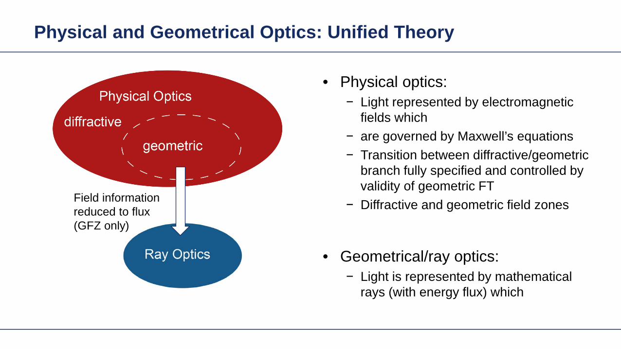
Physical and Geometrical Optics Unified Theory
bull Geometricalray opticsminus Light is represented by mathematical
rays (with energy flux) which
bull Physical opticsminus Light represented by electromagnetic
fields which minus are governed by Maxwellrsquos equationsminus Transition between diffractivegeometric
branch fully specified and controlled by validity of geometric FT
minus Diffractive and geometric field zonesField information reduced to flux (GFZ only)
Physical and Geometrical Optics Unified Theory
Physical opticsbullLight represented by electromagnetic minusfields which are governed by Maxwellminus rsquos equationsTransition between diffractivegeometric minusbranch fully specified and controlled by validity of geometric FTDiffractive and geometric field zonesminus
Physical optics in geometric zones is as fast as ray tracing (with potential to be faster)
Physical and Geometrical Optics Unified Theory
VirtualLab deals with the transitions bullbetween diffractive and geometric branch of physical optics automatically (steady development)
bull Physical opticsminus Light represented by electromagnetic
fields which minus are governed by Maxwellrsquos equationsminus Transition between diffractivegeometric
branch fully specified and controlled by validity of geometric FT
minus Diffractive and geometric field zones
Physical Optics Modeling Regional Maxwellrsquos Solver
Physical Optics Modeling Non-sequential Solver Connection
Fast physical optics approach gives deeper insight in modeling and more flexibility in design
TaskSystem Illustration
Intensity of the interference pattern
Results Ray Dot Diagram at Detector
6 mm
6 m
m
here
6 mm
Mode 1 Mode 2
6 mm
Combined
Results Field at Detector
3 mm
3 m
m
3 mm
Mode 1 Mode 2
3 mm
Combined
here
0
021
Simulation Time ~15 s
Results Field Tracing with Tilt of the Object
3 mm
3 m
m
3 mm
3deg 5deg
3 mm
10deg
here
0
045
0
021
0
016
Example of Multi-Scale Optical System
Example Wafer Inspection System
Base Grating Structure
90nm 90nm 90nm 140nm
50nm
100nm 125nm
substrate thickness = 1mmperiod size
Base Structure Analysis
Intensity Image of Grating after Polarizer in X-Direction
Intensity Image of Grating after Polarizer in Y-Direction
Simulation time few seconds
Base Grating Structure
90nm 90nm 90nm 140nm
50nm
100nm 125nm
substrate thickness = 1mmperiod size
40nm 140nm 90nm 140nm
50nm
100nm 125nm
substrate thickness = 1mmperiod size
Modified Grating Structure
Modified Structure Analysis
Intensity Image of Grating after Polarizer in X-Direction
Intensity Image of Grating after Polarizer in Y-Direction
Fast Physical Optics Freeform Surfaces
Fast Physical Optics Freeform Surfaces
50 simulations
Fast Physical Optics Freeform Surfaces
cpu time per simulation lt 1 sec
Here
Amplitude Ex(xy)
Fast simulation with low number of wavefront samples (similar to number of rays) but
noise-free detector signal
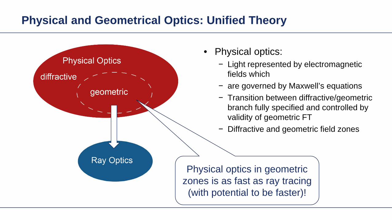
Physical and Geometrical Optics Unified Theory
VirtualLab deals with the transitions bullbetween diffractive and geometric branch of physical optics automatically (steady development)
bull Physical opticsminus Light represented by electromagnetic
fields which minus are governed by Maxwellrsquos equationsminus Transition between diffractivegeometric
branch fully specified and controlled by validity of geometric FT
minus Diffractive and geometric field zones
Physical Optics Modeling Regional Maxwellrsquos Solver
Physical Optics Modeling Non-sequential Solver Connection
Fast physical optics approach gives deeper insight in modeling and more flexibility in design
TaskSystem Illustration
Intensity of the interference pattern
Results Ray Dot Diagram at Detector
6 mm
6 m
m
here
6 mm
Mode 1 Mode 2
6 mm
Combined
Results Field at Detector
3 mm
3 m
m
3 mm
Mode 1 Mode 2
3 mm
Combined
here
0
021
Simulation Time ~15 s
Results Field Tracing with Tilt of the Object
3 mm
3 m
m
3 mm
3deg 5deg
3 mm
10deg
here
0
045
0
021
0
016
Example of Multi-Scale Optical System
Example Wafer Inspection System
Base Grating Structure
90nm 90nm 90nm 140nm
50nm
100nm 125nm
substrate thickness = 1mmperiod size
Base Structure Analysis
Intensity Image of Grating after Polarizer in X-Direction
Intensity Image of Grating after Polarizer in Y-Direction
Simulation time few seconds
Base Grating Structure
90nm 90nm 90nm 140nm
50nm
100nm 125nm
substrate thickness = 1mmperiod size
40nm 140nm 90nm 140nm
50nm
100nm 125nm
substrate thickness = 1mmperiod size
Modified Grating Structure
Modified Structure Analysis
Intensity Image of Grating after Polarizer in X-Direction
Intensity Image of Grating after Polarizer in Y-Direction
Fast Physical Optics Freeform Surfaces
Fast Physical Optics Freeform Surfaces
50 simulations
Fast Physical Optics Freeform Surfaces
cpu time per simulation lt 1 sec
Here
Amplitude Ex(xy)
Fast simulation with low number of wavefront samples (similar to number of rays) but
noise-free detector signal
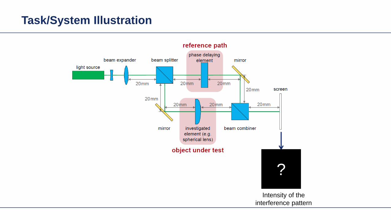
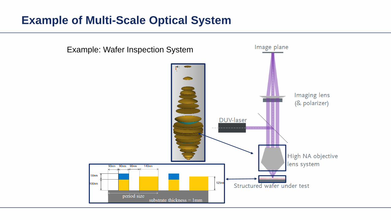

Base Grating Structure
90nm 90nm 90nm 140nm
50nm
100nm 125nm
substrate thickness = 1mmperiod size
Base Structure Analysis
Intensity Image of Grating after Polarizer in X-Direction
Intensity Image of Grating after Polarizer in Y-Direction
Simulation time few seconds
Base Grating Structure
90nm 90nm 90nm 140nm
50nm
100nm 125nm
substrate thickness = 1mmperiod size
40nm 140nm 90nm 140nm
50nm
100nm 125nm
substrate thickness = 1mmperiod size
Modified Grating Structure
Modified Structure Analysis
Intensity Image of Grating after Polarizer in X-Direction
Intensity Image of Grating after Polarizer in Y-Direction
Fast Physical Optics Freeform Surfaces
Fast Physical Optics Freeform Surfaces
50 simulations
Fast Physical Optics Freeform Surfaces
cpu time per simulation lt 1 sec
Here
Amplitude Ex(xy)
Fast simulation with low number of wavefront samples (similar to number of rays) but
noise-free detector signal

Fast Physical Optics Freeform Surfaces
Fast Physical Optics Freeform Surfaces
50 simulations
Fast Physical Optics Freeform Surfaces
cpu time per simulation lt 1 sec
Here
Amplitude Ex(xy)
Fast simulation with low number of wavefront samples (similar to number of rays) but
noise-free detector signal

Fast Physical Optics Freeform Surfaces
50 simulations
Fast Physical Optics Freeform Surfaces
cpu time per simulation lt 1 sec
Here
Amplitude Ex(xy)
Fast simulation with low number of wavefront samples (similar to number of rays) but
noise-free detector signal

Fast Physical Optics Freeform Surfaces
cpu time per simulation lt 1 sec
Here
Amplitude Ex(xy)
Fast simulation with low number of wavefront samples (similar to number of rays) but
noise-free detector signal
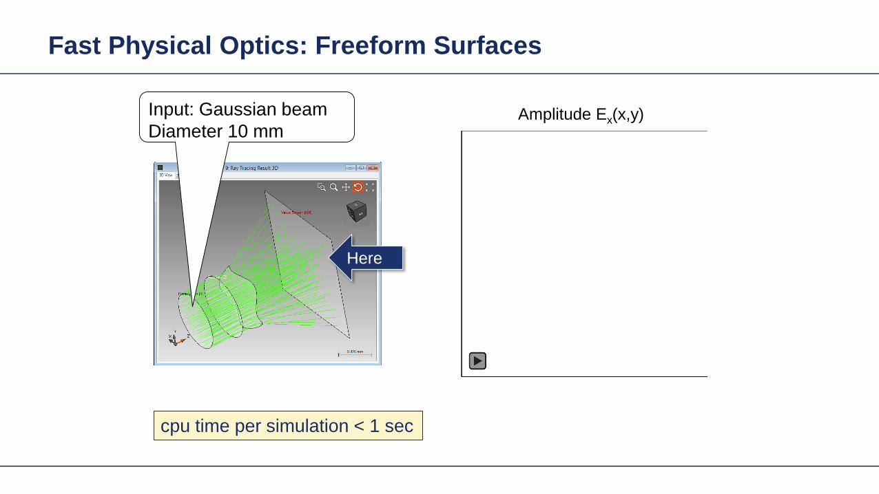
Fast Physical Optics Freeform Surfaces
cpu time per simulation lt 1 sec
Here
Amplitude Ex(xy)Input Gaussian beamDiameter 10 mm

Light Shaping
Intensity in target plane
Related mesh
Light Shaping From a Physical Optics Perspective
Diffractive and geometric concepts
Light Shaping Tasks Cases
Input field consists of one source bullmodeNo restrictions of input field typebull
Shaper Target
Light Shaping Tasks Cases
bull Target in geometric field zone (GFZ)
Shaper in geometric field zone bull(GFZ)
Shaper Target
Light Shaping Tasks Cases
bull Target in geometric field zone (GFZ)
bull Shaper in geometric field zone (GFZ)
Shaper Target
Light Shaping Tasks Cases
bull Target in geometric field zone (GFZ)
bull Shaper in diffractive field zone (DFZ)
Shaper Target
Light Shaping Tasks Cases
Target in diffractive field zone bullbull Shaper in geometric field zone (GFZ)
Shaper Target
Light Shaping Tasks Cases
Target in diffractive field zone bull(DFZ)
bull Shaper in geometric field zones (GFZ)
Shaper 1 Shaper 2 Target
Light shaping in geometric zones
Diffractive (HOE) and refractive (freeform) approaches
Light Shaping Tasks Focussing
Target in diffractive field zone (DFZ)bullbull Shaper in geometric field zone (GFZ)
Shaper Target
Light Shaping Tasks Focussing
Light Shaping Tasks Focussing
local grating sawtooth type
Λ
119889119889 119903119903
119911119911
119879119879
Λ grating period
Λ 119909119909 119910119910 =2120587120587
|120571120571120571120571 119909119909119910119910 |119889119889 modulation depth119879119879 thickness of base blockFor the design the thickness of the base block is set as zero 119879119879 = 0
Light Shaping Tasks Focussing
intensity before the diffractive lens
-1 order 0 order +2 order+1 order
intensity behind the diffractive lens
Modeling with Fourier Modal Method (FMM)
Light Shaping Tasks Focussing
wavefront phase
phase of the working order behind the diffractive lens
residual phase residual phase along cross-section
calculated phase of Rayleigh coefficient of Ex
1 single lens design
Dot pattern of the working order
Ray tracing result Field tracing result
PSF
Example Focusing Lens wo Freeform
Size = 4227120583120583m
dot diagram PSF
Design Concept HOE and Freeform
Lens system 1
Target plane
SourceLens system
2
Signal field
FreeformHOE
Wavefront transformation (Aberration control)
Design Concept HOE and Freeform
Lens system 1
Target plane
SourceLens system
2
Signal fieldDesign step 1 Design in the functional embodimentbull Determination of phase in shaper plane Design step 2 Design in structural embodimentbull Design of HOE or refractive surface in order to
obtain the required phase change
FreeformHOE
Freeform Design Algorithm Example
Lens system 1
SourceLens system
2
Design step 1 Design in the functional embodimentInverse bull field propagation approach
Design step 2 Design in structural embodimentFast recursive design of freeform surface using bullspline interpolation approach based on full phase information (no parametric optimization)
FreeformTarget plane
Signal field
Example Focusing Lens wo Freeform
Size = 4227120583120583m
dot diagram PSF
Example Focusing Lens w Freeform
dot diagram
Size = 208120583120583m
PSFdot diagram PSF
Height Profile(3D view) Height Profile
(2D view)
Direct calculation without optimization in a few seconds
Result without correction with freeform surface
Example Focusing Lens Off-Axis
Freeform surface
3D view 2D view
Size = 076120583120583m
Size = 1279120583120583m
Result without correction with freeform surface
Example Focusing Lens Off-Axis
Freeform surface
3D view 2D view
dot diagram
Size = 076120583120583m
Size = 1279120583120583m
PSF
Direct calculation without optimization in a few seconds
Light Shaping Tasks Geometric Zones Only
Target in geometric field zone bull(GFZ)
bull Shaper in geometric field zone (GFZ)
Shaper Target
Light Shaping Tasks Geometric Zones Only
bull Functional designminus Propagation of field from DFZ into GFZminus Energy conservation leads to identity of
intergal over irradiances in shaper and target planes
minus Together with GFZ assumption phase can be designed
Light Shaping Tasks Geometric Zones Only
Functional designbullPropagation of field from DFZ into GFZminusEnergy conservation leads to identity of minusintergal over irradiances in shaper and target planes Together with GFZ assumption phase minuscan be designed
Light Shaping Tasks Geometric Zones Only
Functional designbullPropagation of field from DFZ into GFZminusEnergy conservation leads to identity of minusintergal over irradiances in shaper and target planes Together with GFZ assumption phase minuscan be designed
Light Shaping Tasks Geometric Zones Only
bull Functional designminus Propagation of field from DFZ into GFZminus Energy conservation leads to identity of
intergal over irradiances in shaper and target planes
minus Together with GFZ assumption phase can be designed
Proc SPIE 1998
Light Shaping Tasks Geometric Zones Only
bull Functional designminus Propagation of field from DFZ into GFZminus Energy conservation leads to identity of
intergal over irradiances in shaper and target planes
minus Together with GFZ assumption phase can be designed
2011
Gaussian to Top-Hat (Non-paraxial)
Gaussian wavehigh NA (001)
input plane
reference plane
target plane
target irradiance
30mm
35mm
35mm2m
m
2mm
20mm
the output NA asymp 04
The Rayleigh lengths of the input Gaussian is 5556microm
Gaussian to Top-Hat (Non-paraxial) Phase Design via Meshes
mesh on reference plane
2mm
2mm
30m
m
30mm
mesh on target plane
Gaussian wavehigh NA (001)
input plane
reference plane
target plane
30mm2mm
2mm
20mm
Gaussian to Top-Hat (Non-paraxial) Functional Embodiment
irradiance at target plane
cross-section (normalized)
Gaussian wavehigh NA (001)
input plane
functional embodiment
target plane
30mm2mm
2mm
20mm
irradiance before the component
irradiance after the component
Gaussian to Top-Hat (Non-paraxial) Functional Embodiment
irradiance at target plane
cross-section (normalized)
Gaussian wavehigh NA (001)
input plane
functional embodiment
target plane
30mm2mm
2mm
20mm
irradiance before the component
irradiance after the component
Resolution of pattern limited by GFZ assumption and NA of system
Light Shaping Tasks Geometric Zones Only
Structural design altrnativesbullFreeform surface design (convergent minusiterative algorithm)HOE design (direct design)minus
bull Functional designminus Propagation of field from DFZ into GFZminus Energy conservation leads to identity of
intergal over irradiances in shaper and target planes
minus Together with GFZ assumption phase can be designed
Gaussian to Top-Hat (Non-paraxial) Freeform Surface
irradiance behind the surface
irradiance at target planeGaussian wavehigh NA (001)
freeform element
target plane
30mm2mm
2mm
20mm
cross-section (normalized)
Height Profile(2D Contour line)
Elliptical Gaussian to Top-Hat (Non-paraxial) Freeform Surface
irradiance behind the surface
irradiance at target planeGaussian wavehigh NA (001)
input plane target
plane
30mm2mm
2mm
20mm
freeform element
cross-section (normalized)
Height Profile(2D Contour line)
Plane Wave to Far Field Pattern (Non-paraxial)
plane wave
input plane
optical element
target plane
target irradiance distribution
100mm
150mm
150mm
14mm
Plane Wave to Far Field Pattern (Non-paraxial) Functional Design
-75
0
-150
75
150mm
-75 0-150 75 150mm
0
-15
15mm
0-15 15mm
mesh on input plane
mesh on target plane
plane wave
input plane
referenceplane
target plane
100mm14mm
Plane Wave to Far Field Pattern (Non-paraxial) Functional
irradiance at target plane(normalized)
error from target irradiance
plane wave
input plane
functional component
target plane
100mm14mm
Resolution of pattern limited by GFZ assumption
Plane Wave to Far Field Pattern (Non-paraxial) Freeform Surface
ray tracing
irradiance at target plane(normalized)
error from target irradianceHeight Profile
(2D Contour line)
Gaussian to Top-Hat (Paraxial) Freeform Surface
Gaussian wavehigh NA (001)
input plane target
plane
300mm
2mm
2mm
20mm
freeformelement
irradiance behind the surface
irradiance at target plane
cross-section (normalized)
Height Profile(2D Contour line)
Field is in slow diffractive field zone
Gaussian to Top-Hat (Paraxial) Freeform Surface
bull Because of paraxial field (slow beams) shaper is in DFZ and not GFZ
bull That results in slight diffractive effects which are not included in design
bull By subsequent iterative Fourier transform algorithm which takes DFZ into account that can be corrected
Gaussian to Top-Hat (Non-paraxial) HOE
Gaussian wavehigh NA (001) HOE
target plane
30mm2mm
2mm
20mm
-1order 0 order +1order
irradiance behind HOE
the output NA asymp 04
Gaussian to Top-Hat (Non-paraxial) HOE
ray tracing result with HOE (with the working order of -1 order)
HOEinputplane
target plane
-1 order
HOEinputplane
target plane
0 order
HOEinputplane
target plane
+1 order
Investigate Rayleigh Coefficient
-1order 0 order +1order
Ex Component behind HOE
cross-section profile result from Grating Toolbox
-1 o
rder
0 or
der
+1 o
rder
the Rayleight coefficient along the cross-section is compared with the result from Grating Toolbox
Modeling with Fourier Modal Method (FMM)
Gaussian to Top-Hat (Non-paraxial) HOE
Gaussian wavehigh NA (001) HOE
target plane
30mm2mm
2mm
20mm
-1order 0 order +1order
irradiance on target plane
Gaussian to Top-Hat (Non-paraxial) Lens + HOE
Gaussian wavehigh NA (001)
HOE target plane
30mm2mm
2mm
20mm
sphericallens
Gaussian to Top-Hat (Non-paraxial) Lens + HOE
Gaussian wavehigh NA (001)
HOE target plane
30mm2mm
2mm
20mm
sphericallens
wavefront behind spherical lens
the Peak-to-Valley wavefront error is 3583120582120582
wavefront error with respect to spherical wavefront
Gaussian to Top-Hat (Non-paraxial) Lens + HOE
The result irradiance on target plane is compared with the previous case without the lens
-1order 0 order +1order
without the lens
with the lens
Light Shaping Tasks Cases
Target in geometric field zone bull(GFZ)
bull Shaper in geometric field zone (GFZ)
Shaper Target
Light Shaping Tasks Gaussian to RingmodeShaper Target
Gaussian to Ringmode Refractive Approach (GFZ)Shaper Target
Gaussian to Ringmode Refractive Approach (GFZ)Shaper Target
Gaussian to Ringmode Diffractive Approach (DFZ)Vortex + Lens Target
DFZ
Gaussian to Ringmode Diffractive Approach (DFZ)Vortex + Lens Target
Diffractive light shaping by coherent superposition
Diffractive beam splitter and diffuser
Shaping by ldquoBeam ScanningrdquoTarget
Basic source mode eg Gaussian
Shaping by ldquoBeam Scanningrdquo
bull Beam splits at shaperbull Field behind shaper is in diffractive field zonebull Shaper is grating DOE
Shaper Target
Target pattern is ldquowrittenrdquo by scanned beam in target plane
Illustration of Deflection
Phase of transmission Intensity in target
Illustration of Deflection
Phase of transmission Intensity in target
Illustration of Deflection
Phase of transmission Intensity in target
Illustration of Deflection
Phase of transmission Intensity in target
Illustration of Deflection
Phase of transmission Intensity in target
Illustration of Deflection Sum
Phase of transmission Intensity in target
Basic Design Situations Splitting
bull Spots overlap in target patten diffractive diffuser
bull Spots in target pattern do not overlap diffractive beam splitter
Basic Design Situations Splitting
bull Spots overlap in target patten diffractive diffuser
Spots in target pattern do not bulloverlap diffractive beam splitter
Shaping by ldquoBeam Scanningrdquo
Amplitude Phase
Iterative Fourier Transform Algorithm
Advanced diffractive optics design techniques
Design technique (IFTA) implemented in VirtualLabtrade
Micro-structured surface profile
Fabricated at IAP University of Jena
Feature Sizes of Element
Feature sizeabout 400 nm
4 height levels
Optical Experiment
Jenaacutes sbquoSkylinelsquo
Comments on Diffuser Technology
Very flexible in light pattern generationbullRobust against adjustment problems bullCoherent light leads to speckle patternbullSize of speckle features can be adjusted by focusing systembullDiffusers work for partially coherent beams bullPartially coherent beams smooth the speckle pattern effect can be simulated bullwith VirtualLabtrade
Diffractive Optics Pattern Generation
Diffuser technology
Diffractive Optics Pattern Generation
Diffuser technology Design very chromatic
Source RGB
Solution by Integrated Diffractive Optics
wwwLightTranscom112
Far Field Propagation
Source Plane Wave RGB Transmission Regions
Waveguide Component
High NA Beam Splitter by Two DOElsquos
Parameter Value amp Unitnumber of orders 11 x 11order separation 1 x 1 degperiod 3035 x 3035 micrompixel size 690 x 690 nmdiscrete height levels 8material fused silica
surfaceprofile
paraxial beam splitter
Specification Second Beam Splitter
Parameter Value amp Unitnumber of orders 5 x 5order separation 11 x 11 degperiod 273 x 273 micrompixel size 130 x 130 nmdiscrete height levels 8material fused silica
surfaceprofile
high-NA beam splitter
Results Spot Diagram
spot diagram
combination of both beam splitter generate 55 x 55 order with 55x 55deg full
opening spread
a
Results Output Evaluation with FMM
Light shaping by lateral decomposition
Elementary cell array components
Array of Deflectors
Array of Deflectors
Deflection can be done by gratings prisms mirrors
TaskSystem Illustration
Cell Array Element
spherical wave(point source)
cell array structurebuilt up withbull prismsbull gratingsbull mirrors
Parameter Description Value amp Unittype RGB LEDemitter size 100 x 100 micromwavelength (473 532 635) nmpolarization right circularly polarized lightnumber of lateral modes 3 x 3Total number of lateral andspectral modes
27
Specification Light Source
Specification Cell Array
Parameter Value amp Unitnumber of cells 100 x 100cell size 125 x 125 micromarray aperture 125 x 125 mm
Results 3D System Ray Tracing
Results Grating Cells Array
spot
dia
gram
inte
nsity
pat
tern
(re
al c
olor
vie
w)
for grating cells array strong dispersion
effects occur
Results Prism Cells Array
spot
dia
gram
inte
nsity
pat
tern
(re
al c
olor
vie
w)
the dispersion is significantly reduced by
using prisms
Results Mirror Cells Array
spot
dia
gram
inte
nsity
pat
tern
(re
al c
olor
vie
w)
due to reflective approach no dispersion
effects occur
Light shaping by lateral decomposition
Lens and freeform array components
Array of Micro-optical Components
Lateral combination of elementary light shaping solutions
TaskSystem Illustration
50 mm Angular Spectrum (Far Field)
LED + collimation optic
aperiodic refractive beam shaper array (aBSA)
camera detector
Specs Light Source
spectrum model
fast and accurate modeling of a white bulllight LEDdesign and analysis an aperiodic bullrefractive beam shaper array to optimize a top hat intensity pattern
Highlightshere
Results Intensity Pattern (real color view)
aperiodic beam shaper array periodic microlens array
a
Summary
Introduction of a geometric branch of physical optics bullwith the help of the geometric Fourier transform Refractive and diffractive light shaping concepts bullfollow a unified theory in physical optics Classification of light shaping concepts dependent of bullpositions of shaper(s) and target in field zones Elementary shaping concepts can be combinedbull
Superposition in same area eg beam splitterminusLaterally combined eg cell arrayminus -type components
Further investigations on the basis of the unified bulltheory will reveal further concepts and deeper understanding of light shaping
bull Designs and simulations done with VirtualLab Fusion software
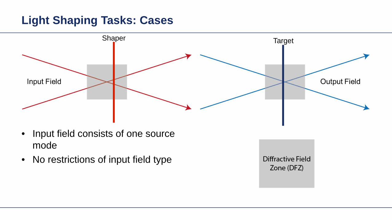
Light Shaping Tasks Cases
bull Target in geometric field zone (GFZ)
bull Shaper in geometric field zone (GFZ)
Shaper Target
Light Shaping Tasks Cases
bull Target in geometric field zone (GFZ)
bull Shaper in diffractive field zone (DFZ)
Shaper Target
Light Shaping Tasks Cases
Target in diffractive field zone bullbull Shaper in geometric field zone (GFZ)
Shaper Target
Light Shaping Tasks Cases
Target in diffractive field zone bull(DFZ)
bull Shaper in geometric field zones (GFZ)
Shaper 1 Shaper 2 Target
Light shaping in geometric zones
Diffractive (HOE) and refractive (freeform) approaches
Light Shaping Tasks Focussing
Target in diffractive field zone (DFZ)bullbull Shaper in geometric field zone (GFZ)
Shaper Target
Light Shaping Tasks Focussing
Light Shaping Tasks Focussing
local grating sawtooth type
Λ
119889119889 119903119903
119911119911
119879119879
Λ grating period
Λ 119909119909 119910119910 =2120587120587
|120571120571120571120571 119909119909119910119910 |119889119889 modulation depth119879119879 thickness of base blockFor the design the thickness of the base block is set as zero 119879119879 = 0
Light Shaping Tasks Focussing
intensity before the diffractive lens
-1 order 0 order +2 order+1 order
intensity behind the diffractive lens
Modeling with Fourier Modal Method (FMM)
Light Shaping Tasks Focussing
wavefront phase
phase of the working order behind the diffractive lens
residual phase residual phase along cross-section
calculated phase of Rayleigh coefficient of Ex
1 single lens design
Dot pattern of the working order
Ray tracing result Field tracing result
PSF
Example Focusing Lens wo Freeform
Size = 4227120583120583m
dot diagram PSF
Design Concept HOE and Freeform
Lens system 1
Target plane
SourceLens system
2
Signal field
FreeformHOE
Wavefront transformation (Aberration control)
Design Concept HOE and Freeform
Lens system 1
Target plane
SourceLens system
2
Signal fieldDesign step 1 Design in the functional embodimentbull Determination of phase in shaper plane Design step 2 Design in structural embodimentbull Design of HOE or refractive surface in order to
obtain the required phase change
FreeformHOE
Freeform Design Algorithm Example
Lens system 1
SourceLens system
2
Design step 1 Design in the functional embodimentInverse bull field propagation approach
Design step 2 Design in structural embodimentFast recursive design of freeform surface using bullspline interpolation approach based on full phase information (no parametric optimization)
FreeformTarget plane
Signal field
Example Focusing Lens wo Freeform
Size = 4227120583120583m
dot diagram PSF
Example Focusing Lens w Freeform
dot diagram
Size = 208120583120583m
PSFdot diagram PSF
Height Profile(3D view) Height Profile
(2D view)
Direct calculation without optimization in a few seconds
Result without correction with freeform surface
Example Focusing Lens Off-Axis
Freeform surface
3D view 2D view
Size = 076120583120583m
Size = 1279120583120583m
Result without correction with freeform surface
Example Focusing Lens Off-Axis
Freeform surface
3D view 2D view
dot diagram
Size = 076120583120583m
Size = 1279120583120583m
PSF
Direct calculation without optimization in a few seconds
Light Shaping Tasks Geometric Zones Only
Target in geometric field zone bull(GFZ)
bull Shaper in geometric field zone (GFZ)
Shaper Target
Light Shaping Tasks Geometric Zones Only
bull Functional designminus Propagation of field from DFZ into GFZminus Energy conservation leads to identity of
intergal over irradiances in shaper and target planes
minus Together with GFZ assumption phase can be designed
Light Shaping Tasks Geometric Zones Only
Functional designbullPropagation of field from DFZ into GFZminusEnergy conservation leads to identity of minusintergal over irradiances in shaper and target planes Together with GFZ assumption phase minuscan be designed
Light Shaping Tasks Geometric Zones Only
Functional designbullPropagation of field from DFZ into GFZminusEnergy conservation leads to identity of minusintergal over irradiances in shaper and target planes Together with GFZ assumption phase minuscan be designed
Light Shaping Tasks Geometric Zones Only
bull Functional designminus Propagation of field from DFZ into GFZminus Energy conservation leads to identity of
intergal over irradiances in shaper and target planes
minus Together with GFZ assumption phase can be designed
Proc SPIE 1998
Light Shaping Tasks Geometric Zones Only
bull Functional designminus Propagation of field from DFZ into GFZminus Energy conservation leads to identity of
intergal over irradiances in shaper and target planes
minus Together with GFZ assumption phase can be designed
2011
Gaussian to Top-Hat (Non-paraxial)
Gaussian wavehigh NA (001)
input plane
reference plane
target plane
target irradiance
30mm
35mm
35mm2m
m
2mm
20mm
the output NA asymp 04
The Rayleigh lengths of the input Gaussian is 5556microm
Gaussian to Top-Hat (Non-paraxial) Phase Design via Meshes
mesh on reference plane
2mm
2mm
30m
m
30mm
mesh on target plane
Gaussian wavehigh NA (001)
input plane
reference plane
target plane
30mm2mm
2mm
20mm
Gaussian to Top-Hat (Non-paraxial) Functional Embodiment
irradiance at target plane
cross-section (normalized)
Gaussian wavehigh NA (001)
input plane
functional embodiment
target plane
30mm2mm
2mm
20mm
irradiance before the component
irradiance after the component
Gaussian to Top-Hat (Non-paraxial) Functional Embodiment
irradiance at target plane
cross-section (normalized)
Gaussian wavehigh NA (001)
input plane
functional embodiment
target plane
30mm2mm
2mm
20mm
irradiance before the component
irradiance after the component
Resolution of pattern limited by GFZ assumption and NA of system
Light Shaping Tasks Geometric Zones Only
Structural design altrnativesbullFreeform surface design (convergent minusiterative algorithm)HOE design (direct design)minus
bull Functional designminus Propagation of field from DFZ into GFZminus Energy conservation leads to identity of
intergal over irradiances in shaper and target planes
minus Together with GFZ assumption phase can be designed
Gaussian to Top-Hat (Non-paraxial) Freeform Surface
irradiance behind the surface
irradiance at target planeGaussian wavehigh NA (001)
freeform element
target plane
30mm2mm
2mm
20mm
cross-section (normalized)
Height Profile(2D Contour line)
Elliptical Gaussian to Top-Hat (Non-paraxial) Freeform Surface
irradiance behind the surface
irradiance at target planeGaussian wavehigh NA (001)
input plane target
plane
30mm2mm
2mm
20mm
freeform element
cross-section (normalized)
Height Profile(2D Contour line)
Plane Wave to Far Field Pattern (Non-paraxial)
plane wave
input plane
optical element
target plane
target irradiance distribution
100mm
150mm
150mm
14mm
Plane Wave to Far Field Pattern (Non-paraxial) Functional Design
-75
0
-150
75
150mm
-75 0-150 75 150mm
0
-15
15mm
0-15 15mm
mesh on input plane
mesh on target plane
plane wave
input plane
referenceplane
target plane
100mm14mm
Plane Wave to Far Field Pattern (Non-paraxial) Functional
irradiance at target plane(normalized)
error from target irradiance
plane wave
input plane
functional component
target plane
100mm14mm
Resolution of pattern limited by GFZ assumption
Plane Wave to Far Field Pattern (Non-paraxial) Freeform Surface
ray tracing
irradiance at target plane(normalized)
error from target irradianceHeight Profile
(2D Contour line)
Gaussian to Top-Hat (Paraxial) Freeform Surface
Gaussian wavehigh NA (001)
input plane target
plane
300mm
2mm
2mm
20mm
freeformelement
irradiance behind the surface
irradiance at target plane
cross-section (normalized)
Height Profile(2D Contour line)
Field is in slow diffractive field zone
Gaussian to Top-Hat (Paraxial) Freeform Surface
bull Because of paraxial field (slow beams) shaper is in DFZ and not GFZ
bull That results in slight diffractive effects which are not included in design
bull By subsequent iterative Fourier transform algorithm which takes DFZ into account that can be corrected
Gaussian to Top-Hat (Non-paraxial) HOE
Gaussian wavehigh NA (001) HOE
target plane
30mm2mm
2mm
20mm
-1order 0 order +1order
irradiance behind HOE
the output NA asymp 04
Gaussian to Top-Hat (Non-paraxial) HOE
ray tracing result with HOE (with the working order of -1 order)
HOEinputplane
target plane
-1 order
HOEinputplane
target plane
0 order
HOEinputplane
target plane
+1 order
Investigate Rayleigh Coefficient
-1order 0 order +1order
Ex Component behind HOE
cross-section profile result from Grating Toolbox
-1 o
rder
0 or
der
+1 o
rder
the Rayleight coefficient along the cross-section is compared with the result from Grating Toolbox
Modeling with Fourier Modal Method (FMM)
Gaussian to Top-Hat (Non-paraxial) HOE
Gaussian wavehigh NA (001) HOE
target plane
30mm2mm
2mm
20mm
-1order 0 order +1order
irradiance on target plane
Gaussian to Top-Hat (Non-paraxial) Lens + HOE
Gaussian wavehigh NA (001)
HOE target plane
30mm2mm
2mm
20mm
sphericallens
Gaussian to Top-Hat (Non-paraxial) Lens + HOE
Gaussian wavehigh NA (001)
HOE target plane
30mm2mm
2mm
20mm
sphericallens
wavefront behind spherical lens
the Peak-to-Valley wavefront error is 3583120582120582
wavefront error with respect to spherical wavefront
Gaussian to Top-Hat (Non-paraxial) Lens + HOE
The result irradiance on target plane is compared with the previous case without the lens
-1order 0 order +1order
without the lens
with the lens
Light Shaping Tasks Cases
Target in geometric field zone bull(GFZ)
bull Shaper in geometric field zone (GFZ)
Shaper Target
Light Shaping Tasks Gaussian to RingmodeShaper Target
Gaussian to Ringmode Refractive Approach (GFZ)Shaper Target
Gaussian to Ringmode Refractive Approach (GFZ)Shaper Target
Gaussian to Ringmode Diffractive Approach (DFZ)Vortex + Lens Target
DFZ
Gaussian to Ringmode Diffractive Approach (DFZ)Vortex + Lens Target
Diffractive light shaping by coherent superposition
Diffractive beam splitter and diffuser
Shaping by ldquoBeam ScanningrdquoTarget
Basic source mode eg Gaussian
Shaping by ldquoBeam Scanningrdquo
bull Beam splits at shaperbull Field behind shaper is in diffractive field zonebull Shaper is grating DOE
Shaper Target
Target pattern is ldquowrittenrdquo by scanned beam in target plane
Illustration of Deflection
Phase of transmission Intensity in target
Illustration of Deflection
Phase of transmission Intensity in target
Illustration of Deflection
Phase of transmission Intensity in target
Illustration of Deflection
Phase of transmission Intensity in target
Illustration of Deflection
Phase of transmission Intensity in target
Illustration of Deflection Sum
Phase of transmission Intensity in target
Basic Design Situations Splitting
bull Spots overlap in target patten diffractive diffuser
bull Spots in target pattern do not overlap diffractive beam splitter
Basic Design Situations Splitting
bull Spots overlap in target patten diffractive diffuser
Spots in target pattern do not bulloverlap diffractive beam splitter
Shaping by ldquoBeam Scanningrdquo
Amplitude Phase
Iterative Fourier Transform Algorithm
Advanced diffractive optics design techniques
Design technique (IFTA) implemented in VirtualLabtrade
Micro-structured surface profile
Fabricated at IAP University of Jena
Feature Sizes of Element
Feature sizeabout 400 nm
4 height levels
Optical Experiment
Jenaacutes sbquoSkylinelsquo
Comments on Diffuser Technology
Very flexible in light pattern generationbullRobust against adjustment problems bullCoherent light leads to speckle patternbullSize of speckle features can be adjusted by focusing systembullDiffusers work for partially coherent beams bullPartially coherent beams smooth the speckle pattern effect can be simulated bullwith VirtualLabtrade
Diffractive Optics Pattern Generation
Diffuser technology
Diffractive Optics Pattern Generation
Diffuser technology Design very chromatic
Source RGB
Solution by Integrated Diffractive Optics
wwwLightTranscom112
Far Field Propagation
Source Plane Wave RGB Transmission Regions
Waveguide Component
High NA Beam Splitter by Two DOElsquos
Parameter Value amp Unitnumber of orders 11 x 11order separation 1 x 1 degperiod 3035 x 3035 micrompixel size 690 x 690 nmdiscrete height levels 8material fused silica
surfaceprofile
paraxial beam splitter
Specification Second Beam Splitter
Parameter Value amp Unitnumber of orders 5 x 5order separation 11 x 11 degperiod 273 x 273 micrompixel size 130 x 130 nmdiscrete height levels 8material fused silica
surfaceprofile
high-NA beam splitter
Results Spot Diagram
spot diagram
combination of both beam splitter generate 55 x 55 order with 55x 55deg full
opening spread
a
Results Output Evaluation with FMM
Light shaping by lateral decomposition
Elementary cell array components
Array of Deflectors
Array of Deflectors
Deflection can be done by gratings prisms mirrors
TaskSystem Illustration
Cell Array Element
spherical wave(point source)
cell array structurebuilt up withbull prismsbull gratingsbull mirrors
Parameter Description Value amp Unittype RGB LEDemitter size 100 x 100 micromwavelength (473 532 635) nmpolarization right circularly polarized lightnumber of lateral modes 3 x 3Total number of lateral andspectral modes
27
Specification Light Source
Specification Cell Array
Parameter Value amp Unitnumber of cells 100 x 100cell size 125 x 125 micromarray aperture 125 x 125 mm
Results 3D System Ray Tracing
Results Grating Cells Array
spot
dia
gram
inte
nsity
pat
tern
(re
al c
olor
vie
w)
for grating cells array strong dispersion
effects occur
Results Prism Cells Array
spot
dia
gram
inte
nsity
pat
tern
(re
al c
olor
vie
w)
the dispersion is significantly reduced by
using prisms
Results Mirror Cells Array
spot
dia
gram
inte
nsity
pat
tern
(re
al c
olor
vie
w)
due to reflective approach no dispersion
effects occur
Light shaping by lateral decomposition
Lens and freeform array components
Array of Micro-optical Components
Lateral combination of elementary light shaping solutions
TaskSystem Illustration
50 mm Angular Spectrum (Far Field)
LED + collimation optic
aperiodic refractive beam shaper array (aBSA)
camera detector
Specs Light Source
spectrum model
fast and accurate modeling of a white bulllight LEDdesign and analysis an aperiodic bullrefractive beam shaper array to optimize a top hat intensity pattern
Highlightshere
Results Intensity Pattern (real color view)
aperiodic beam shaper array periodic microlens array
a
Summary
Introduction of a geometric branch of physical optics bullwith the help of the geometric Fourier transform Refractive and diffractive light shaping concepts bullfollow a unified theory in physical optics Classification of light shaping concepts dependent of bullpositions of shaper(s) and target in field zones Elementary shaping concepts can be combinedbull
Superposition in same area eg beam splitterminusLaterally combined eg cell arrayminus -type components
Further investigations on the basis of the unified bulltheory will reveal further concepts and deeper understanding of light shaping
bull Designs and simulations done with VirtualLab Fusion software

Light Shaping Tasks Cases
bull Target in geometric field zone (GFZ)
bull Shaper in diffractive field zone (DFZ)
Shaper Target
Light Shaping Tasks Cases
Target in diffractive field zone bullbull Shaper in geometric field zone (GFZ)
Shaper Target
Light Shaping Tasks Cases
Target in diffractive field zone bull(DFZ)
bull Shaper in geometric field zones (GFZ)
Shaper 1 Shaper 2 Target
Light shaping in geometric zones
Diffractive (HOE) and refractive (freeform) approaches
Light Shaping Tasks Focussing
Target in diffractive field zone (DFZ)bullbull Shaper in geometric field zone (GFZ)
Shaper Target
Light Shaping Tasks Focussing
Light Shaping Tasks Focussing
local grating sawtooth type
Λ
119889119889 119903119903
119911119911
119879119879
Λ grating period
Λ 119909119909 119910119910 =2120587120587
|120571120571120571120571 119909119909119910119910 |119889119889 modulation depth119879119879 thickness of base blockFor the design the thickness of the base block is set as zero 119879119879 = 0
Light Shaping Tasks Focussing
intensity before the diffractive lens
-1 order 0 order +2 order+1 order
intensity behind the diffractive lens
Modeling with Fourier Modal Method (FMM)
Light Shaping Tasks Focussing
wavefront phase
phase of the working order behind the diffractive lens
residual phase residual phase along cross-section
calculated phase of Rayleigh coefficient of Ex
1 single lens design
Dot pattern of the working order
Ray tracing result Field tracing result
PSF
Example Focusing Lens wo Freeform
Size = 4227120583120583m
dot diagram PSF
Design Concept HOE and Freeform
Lens system 1
Target plane
SourceLens system
2
Signal field
FreeformHOE
Wavefront transformation (Aberration control)
Design Concept HOE and Freeform
Lens system 1
Target plane
SourceLens system
2
Signal fieldDesign step 1 Design in the functional embodimentbull Determination of phase in shaper plane Design step 2 Design in structural embodimentbull Design of HOE or refractive surface in order to
obtain the required phase change
FreeformHOE
Freeform Design Algorithm Example
Lens system 1
SourceLens system
2
Design step 1 Design in the functional embodimentInverse bull field propagation approach
Design step 2 Design in structural embodimentFast recursive design of freeform surface using bullspline interpolation approach based on full phase information (no parametric optimization)
FreeformTarget plane
Signal field
Example Focusing Lens wo Freeform
Size = 4227120583120583m
dot diagram PSF
Example Focusing Lens w Freeform
dot diagram
Size = 208120583120583m
PSFdot diagram PSF
Height Profile(3D view) Height Profile
(2D view)
Direct calculation without optimization in a few seconds
Result without correction with freeform surface
Example Focusing Lens Off-Axis
Freeform surface
3D view 2D view
Size = 076120583120583m
Size = 1279120583120583m
Result without correction with freeform surface
Example Focusing Lens Off-Axis
Freeform surface
3D view 2D view
dot diagram
Size = 076120583120583m
Size = 1279120583120583m
PSF
Direct calculation without optimization in a few seconds
Light Shaping Tasks Geometric Zones Only
Target in geometric field zone bull(GFZ)
bull Shaper in geometric field zone (GFZ)
Shaper Target
Light Shaping Tasks Geometric Zones Only
bull Functional designminus Propagation of field from DFZ into GFZminus Energy conservation leads to identity of
intergal over irradiances in shaper and target planes
minus Together with GFZ assumption phase can be designed
Light Shaping Tasks Geometric Zones Only
Functional designbullPropagation of field from DFZ into GFZminusEnergy conservation leads to identity of minusintergal over irradiances in shaper and target planes Together with GFZ assumption phase minuscan be designed
Light Shaping Tasks Geometric Zones Only
Functional designbullPropagation of field from DFZ into GFZminusEnergy conservation leads to identity of minusintergal over irradiances in shaper and target planes Together with GFZ assumption phase minuscan be designed
Light Shaping Tasks Geometric Zones Only
bull Functional designminus Propagation of field from DFZ into GFZminus Energy conservation leads to identity of
intergal over irradiances in shaper and target planes
minus Together with GFZ assumption phase can be designed
Proc SPIE 1998
Light Shaping Tasks Geometric Zones Only
bull Functional designminus Propagation of field from DFZ into GFZminus Energy conservation leads to identity of
intergal over irradiances in shaper and target planes
minus Together with GFZ assumption phase can be designed
2011
Gaussian to Top-Hat (Non-paraxial)
Gaussian wavehigh NA (001)
input plane
reference plane
target plane
target irradiance
30mm
35mm
35mm2m
m
2mm
20mm
the output NA asymp 04
The Rayleigh lengths of the input Gaussian is 5556microm
Gaussian to Top-Hat (Non-paraxial) Phase Design via Meshes
mesh on reference plane
2mm
2mm
30m
m
30mm
mesh on target plane
Gaussian wavehigh NA (001)
input plane
reference plane
target plane
30mm2mm
2mm
20mm
Gaussian to Top-Hat (Non-paraxial) Functional Embodiment
irradiance at target plane
cross-section (normalized)
Gaussian wavehigh NA (001)
input plane
functional embodiment
target plane
30mm2mm
2mm
20mm
irradiance before the component
irradiance after the component
Gaussian to Top-Hat (Non-paraxial) Functional Embodiment
irradiance at target plane
cross-section (normalized)
Gaussian wavehigh NA (001)
input plane
functional embodiment
target plane
30mm2mm
2mm
20mm
irradiance before the component
irradiance after the component
Resolution of pattern limited by GFZ assumption and NA of system
Light Shaping Tasks Geometric Zones Only
Structural design altrnativesbullFreeform surface design (convergent minusiterative algorithm)HOE design (direct design)minus
bull Functional designminus Propagation of field from DFZ into GFZminus Energy conservation leads to identity of
intergal over irradiances in shaper and target planes
minus Together with GFZ assumption phase can be designed
Gaussian to Top-Hat (Non-paraxial) Freeform Surface
irradiance behind the surface
irradiance at target planeGaussian wavehigh NA (001)
freeform element
target plane
30mm2mm
2mm
20mm
cross-section (normalized)
Height Profile(2D Contour line)
Elliptical Gaussian to Top-Hat (Non-paraxial) Freeform Surface
irradiance behind the surface
irradiance at target planeGaussian wavehigh NA (001)
input plane target
plane
30mm2mm
2mm
20mm
freeform element
cross-section (normalized)
Height Profile(2D Contour line)
Plane Wave to Far Field Pattern (Non-paraxial)
plane wave
input plane
optical element
target plane
target irradiance distribution
100mm
150mm
150mm
14mm
Plane Wave to Far Field Pattern (Non-paraxial) Functional Design
-75
0
-150
75
150mm
-75 0-150 75 150mm
0
-15
15mm
0-15 15mm
mesh on input plane
mesh on target plane
plane wave
input plane
referenceplane
target plane
100mm14mm
Plane Wave to Far Field Pattern (Non-paraxial) Functional
irradiance at target plane(normalized)
error from target irradiance
plane wave
input plane
functional component
target plane
100mm14mm
Resolution of pattern limited by GFZ assumption
Plane Wave to Far Field Pattern (Non-paraxial) Freeform Surface
ray tracing
irradiance at target plane(normalized)
error from target irradianceHeight Profile
(2D Contour line)
Gaussian to Top-Hat (Paraxial) Freeform Surface
Gaussian wavehigh NA (001)
input plane target
plane
300mm
2mm
2mm
20mm
freeformelement
irradiance behind the surface
irradiance at target plane
cross-section (normalized)
Height Profile(2D Contour line)
Field is in slow diffractive field zone
Gaussian to Top-Hat (Paraxial) Freeform Surface
bull Because of paraxial field (slow beams) shaper is in DFZ and not GFZ
bull That results in slight diffractive effects which are not included in design
bull By subsequent iterative Fourier transform algorithm which takes DFZ into account that can be corrected
Gaussian to Top-Hat (Non-paraxial) HOE
Gaussian wavehigh NA (001) HOE
target plane
30mm2mm
2mm
20mm
-1order 0 order +1order
irradiance behind HOE
the output NA asymp 04
Gaussian to Top-Hat (Non-paraxial) HOE
ray tracing result with HOE (with the working order of -1 order)
HOEinputplane
target plane
-1 order
HOEinputplane
target plane
0 order
HOEinputplane
target plane
+1 order
Investigate Rayleigh Coefficient
-1order 0 order +1order
Ex Component behind HOE
cross-section profile result from Grating Toolbox
-1 o
rder
0 or
der
+1 o
rder
the Rayleight coefficient along the cross-section is compared with the result from Grating Toolbox
Modeling with Fourier Modal Method (FMM)
Gaussian to Top-Hat (Non-paraxial) HOE
Gaussian wavehigh NA (001) HOE
target plane
30mm2mm
2mm
20mm
-1order 0 order +1order
irradiance on target plane
Gaussian to Top-Hat (Non-paraxial) Lens + HOE
Gaussian wavehigh NA (001)
HOE target plane
30mm2mm
2mm
20mm
sphericallens
Gaussian to Top-Hat (Non-paraxial) Lens + HOE
Gaussian wavehigh NA (001)
HOE target plane
30mm2mm
2mm
20mm
sphericallens
wavefront behind spherical lens
the Peak-to-Valley wavefront error is 3583120582120582
wavefront error with respect to spherical wavefront
Gaussian to Top-Hat (Non-paraxial) Lens + HOE
The result irradiance on target plane is compared with the previous case without the lens
-1order 0 order +1order
without the lens
with the lens
Light Shaping Tasks Cases
Target in geometric field zone bull(GFZ)
bull Shaper in geometric field zone (GFZ)
Shaper Target
Light Shaping Tasks Gaussian to RingmodeShaper Target
Gaussian to Ringmode Refractive Approach (GFZ)Shaper Target
Gaussian to Ringmode Refractive Approach (GFZ)Shaper Target
Gaussian to Ringmode Diffractive Approach (DFZ)Vortex + Lens Target
DFZ
Gaussian to Ringmode Diffractive Approach (DFZ)Vortex + Lens Target
Diffractive light shaping by coherent superposition
Diffractive beam splitter and diffuser
Shaping by ldquoBeam ScanningrdquoTarget
Basic source mode eg Gaussian
Shaping by ldquoBeam Scanningrdquo
bull Beam splits at shaperbull Field behind shaper is in diffractive field zonebull Shaper is grating DOE
Shaper Target
Target pattern is ldquowrittenrdquo by scanned beam in target plane
Illustration of Deflection
Phase of transmission Intensity in target
Illustration of Deflection
Phase of transmission Intensity in target
Illustration of Deflection
Phase of transmission Intensity in target
Illustration of Deflection
Phase of transmission Intensity in target
Illustration of Deflection
Phase of transmission Intensity in target
Illustration of Deflection Sum
Phase of transmission Intensity in target
Basic Design Situations Splitting
bull Spots overlap in target patten diffractive diffuser
bull Spots in target pattern do not overlap diffractive beam splitter
Basic Design Situations Splitting
bull Spots overlap in target patten diffractive diffuser
Spots in target pattern do not bulloverlap diffractive beam splitter
Shaping by ldquoBeam Scanningrdquo
Amplitude Phase
Iterative Fourier Transform Algorithm
Advanced diffractive optics design techniques
Design technique (IFTA) implemented in VirtualLabtrade
Micro-structured surface profile
Fabricated at IAP University of Jena
Feature Sizes of Element
Feature sizeabout 400 nm
4 height levels
Optical Experiment
Jenaacutes sbquoSkylinelsquo
Comments on Diffuser Technology
Very flexible in light pattern generationbullRobust against adjustment problems bullCoherent light leads to speckle patternbullSize of speckle features can be adjusted by focusing systembullDiffusers work for partially coherent beams bullPartially coherent beams smooth the speckle pattern effect can be simulated bullwith VirtualLabtrade
Diffractive Optics Pattern Generation
Diffuser technology
Diffractive Optics Pattern Generation
Diffuser technology Design very chromatic
Source RGB
Solution by Integrated Diffractive Optics
wwwLightTranscom112
Far Field Propagation
Source Plane Wave RGB Transmission Regions
Waveguide Component
High NA Beam Splitter by Two DOElsquos
Parameter Value amp Unitnumber of orders 11 x 11order separation 1 x 1 degperiod 3035 x 3035 micrompixel size 690 x 690 nmdiscrete height levels 8material fused silica
surfaceprofile
paraxial beam splitter
Specification Second Beam Splitter
Parameter Value amp Unitnumber of orders 5 x 5order separation 11 x 11 degperiod 273 x 273 micrompixel size 130 x 130 nmdiscrete height levels 8material fused silica
surfaceprofile
high-NA beam splitter
Results Spot Diagram
spot diagram
combination of both beam splitter generate 55 x 55 order with 55x 55deg full
opening spread
a
Results Output Evaluation with FMM
Light shaping by lateral decomposition
Elementary cell array components
Array of Deflectors
Array of Deflectors
Deflection can be done by gratings prisms mirrors
TaskSystem Illustration
Cell Array Element
spherical wave(point source)
cell array structurebuilt up withbull prismsbull gratingsbull mirrors
Parameter Description Value amp Unittype RGB LEDemitter size 100 x 100 micromwavelength (473 532 635) nmpolarization right circularly polarized lightnumber of lateral modes 3 x 3Total number of lateral andspectral modes
27
Specification Light Source
Specification Cell Array
Parameter Value amp Unitnumber of cells 100 x 100cell size 125 x 125 micromarray aperture 125 x 125 mm
Results 3D System Ray Tracing
Results Grating Cells Array
spot
dia
gram
inte
nsity
pat
tern
(re
al c
olor
vie
w)
for grating cells array strong dispersion
effects occur
Results Prism Cells Array
spot
dia
gram
inte
nsity
pat
tern
(re
al c
olor
vie
w)
the dispersion is significantly reduced by
using prisms
Results Mirror Cells Array
spot
dia
gram
inte
nsity
pat
tern
(re
al c
olor
vie
w)
due to reflective approach no dispersion
effects occur
Light shaping by lateral decomposition
Lens and freeform array components
Array of Micro-optical Components
Lateral combination of elementary light shaping solutions
TaskSystem Illustration
50 mm Angular Spectrum (Far Field)
LED + collimation optic
aperiodic refractive beam shaper array (aBSA)
camera detector
Specs Light Source
spectrum model
fast and accurate modeling of a white bulllight LEDdesign and analysis an aperiodic bullrefractive beam shaper array to optimize a top hat intensity pattern
Highlightshere
Results Intensity Pattern (real color view)
aperiodic beam shaper array periodic microlens array
a
Summary
Introduction of a geometric branch of physical optics bullwith the help of the geometric Fourier transform Refractive and diffractive light shaping concepts bullfollow a unified theory in physical optics Classification of light shaping concepts dependent of bullpositions of shaper(s) and target in field zones Elementary shaping concepts can be combinedbull
Superposition in same area eg beam splitterminusLaterally combined eg cell arrayminus -type components
Further investigations on the basis of the unified bulltheory will reveal further concepts and deeper understanding of light shaping
bull Designs and simulations done with VirtualLab Fusion software
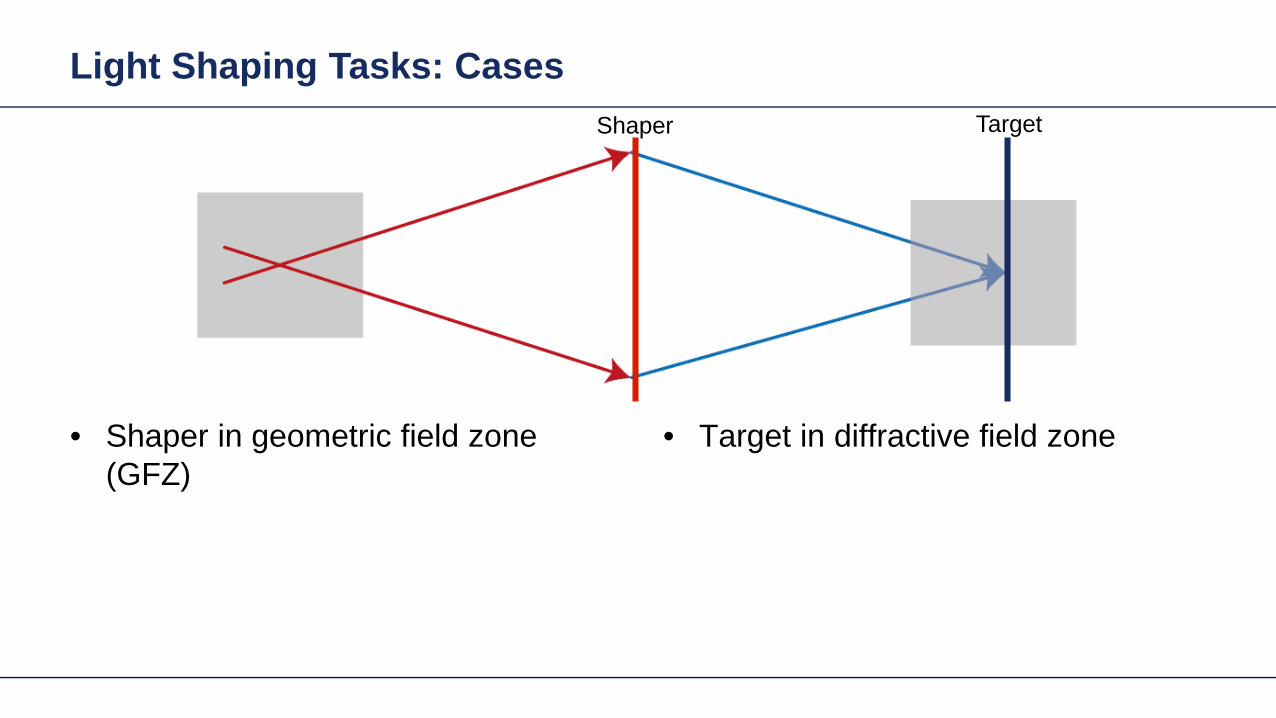
Light Shaping Tasks Cases
Target in diffractive field zone bull(DFZ)
bull Shaper in geometric field zones (GFZ)
Shaper 1 Shaper 2 Target
Light shaping in geometric zones
Diffractive (HOE) and refractive (freeform) approaches
Light Shaping Tasks Focussing
Target in diffractive field zone (DFZ)bullbull Shaper in geometric field zone (GFZ)
Shaper Target
Light Shaping Tasks Focussing
Light Shaping Tasks Focussing
local grating sawtooth type
Λ
119889119889 119903119903
119911119911
119879119879
Λ grating period
Λ 119909119909 119910119910 =2120587120587
|120571120571120571120571 119909119909119910119910 |119889119889 modulation depth119879119879 thickness of base blockFor the design the thickness of the base block is set as zero 119879119879 = 0
Light Shaping Tasks Focussing
intensity before the diffractive lens
-1 order 0 order +2 order+1 order
intensity behind the diffractive lens
Modeling with Fourier Modal Method (FMM)
Light Shaping Tasks Focussing
wavefront phase
phase of the working order behind the diffractive lens
residual phase residual phase along cross-section
calculated phase of Rayleigh coefficient of Ex
1 single lens design
Dot pattern of the working order
Ray tracing result Field tracing result
PSF
Example Focusing Lens wo Freeform
Size = 4227120583120583m
dot diagram PSF
Design Concept HOE and Freeform
Lens system 1
Target plane
SourceLens system
2
Signal field
FreeformHOE
Wavefront transformation (Aberration control)
Design Concept HOE and Freeform
Lens system 1
Target plane
SourceLens system
2
Signal fieldDesign step 1 Design in the functional embodimentbull Determination of phase in shaper plane Design step 2 Design in structural embodimentbull Design of HOE or refractive surface in order to
obtain the required phase change
FreeformHOE
Freeform Design Algorithm Example
Lens system 1
SourceLens system
2
Design step 1 Design in the functional embodimentInverse bull field propagation approach
Design step 2 Design in structural embodimentFast recursive design of freeform surface using bullspline interpolation approach based on full phase information (no parametric optimization)
FreeformTarget plane
Signal field
Example Focusing Lens wo Freeform
Size = 4227120583120583m
dot diagram PSF
Example Focusing Lens w Freeform
dot diagram
Size = 208120583120583m
PSFdot diagram PSF
Height Profile(3D view) Height Profile
(2D view)
Direct calculation without optimization in a few seconds
Result without correction with freeform surface
Example Focusing Lens Off-Axis
Freeform surface
3D view 2D view
Size = 076120583120583m
Size = 1279120583120583m
Result without correction with freeform surface
Example Focusing Lens Off-Axis
Freeform surface
3D view 2D view
dot diagram
Size = 076120583120583m
Size = 1279120583120583m
PSF
Direct calculation without optimization in a few seconds
Light Shaping Tasks Geometric Zones Only
Target in geometric field zone bull(GFZ)
bull Shaper in geometric field zone (GFZ)
Shaper Target
Light Shaping Tasks Geometric Zones Only
bull Functional designminus Propagation of field from DFZ into GFZminus Energy conservation leads to identity of
intergal over irradiances in shaper and target planes
minus Together with GFZ assumption phase can be designed
Light Shaping Tasks Geometric Zones Only
Functional designbullPropagation of field from DFZ into GFZminusEnergy conservation leads to identity of minusintergal over irradiances in shaper and target planes Together with GFZ assumption phase minuscan be designed
Light Shaping Tasks Geometric Zones Only
Functional designbullPropagation of field from DFZ into GFZminusEnergy conservation leads to identity of minusintergal over irradiances in shaper and target planes Together with GFZ assumption phase minuscan be designed
Light Shaping Tasks Geometric Zones Only
bull Functional designminus Propagation of field from DFZ into GFZminus Energy conservation leads to identity of
intergal over irradiances in shaper and target planes
minus Together with GFZ assumption phase can be designed
Proc SPIE 1998
Light Shaping Tasks Geometric Zones Only
bull Functional designminus Propagation of field from DFZ into GFZminus Energy conservation leads to identity of
intergal over irradiances in shaper and target planes
minus Together with GFZ assumption phase can be designed
2011
Gaussian to Top-Hat (Non-paraxial)
Gaussian wavehigh NA (001)
input plane
reference plane
target plane
target irradiance
30mm
35mm
35mm2m
m
2mm
20mm
the output NA asymp 04
The Rayleigh lengths of the input Gaussian is 5556microm
Gaussian to Top-Hat (Non-paraxial) Phase Design via Meshes
mesh on reference plane
2mm
2mm
30m
m
30mm
mesh on target plane
Gaussian wavehigh NA (001)
input plane
reference plane
target plane
30mm2mm
2mm
20mm
Gaussian to Top-Hat (Non-paraxial) Functional Embodiment
irradiance at target plane
cross-section (normalized)
Gaussian wavehigh NA (001)
input plane
functional embodiment
target plane
30mm2mm
2mm
20mm
irradiance before the component
irradiance after the component
Gaussian to Top-Hat (Non-paraxial) Functional Embodiment
irradiance at target plane
cross-section (normalized)
Gaussian wavehigh NA (001)
input plane
functional embodiment
target plane
30mm2mm
2mm
20mm
irradiance before the component
irradiance after the component
Resolution of pattern limited by GFZ assumption and NA of system
Light Shaping Tasks Geometric Zones Only
Structural design altrnativesbullFreeform surface design (convergent minusiterative algorithm)HOE design (direct design)minus
bull Functional designminus Propagation of field from DFZ into GFZminus Energy conservation leads to identity of
intergal over irradiances in shaper and target planes
minus Together with GFZ assumption phase can be designed
Gaussian to Top-Hat (Non-paraxial) Freeform Surface
irradiance behind the surface
irradiance at target planeGaussian wavehigh NA (001)
freeform element
target plane
30mm2mm
2mm
20mm
cross-section (normalized)
Height Profile(2D Contour line)
Elliptical Gaussian to Top-Hat (Non-paraxial) Freeform Surface
irradiance behind the surface
irradiance at target planeGaussian wavehigh NA (001)
input plane target
plane
30mm2mm
2mm
20mm
freeform element
cross-section (normalized)
Height Profile(2D Contour line)
Plane Wave to Far Field Pattern (Non-paraxial)
plane wave
input plane
optical element
target plane
target irradiance distribution
100mm
150mm
150mm
14mm
Plane Wave to Far Field Pattern (Non-paraxial) Functional Design
-75
0
-150
75
150mm
-75 0-150 75 150mm
0
-15
15mm
0-15 15mm
mesh on input plane
mesh on target plane
plane wave
input plane
referenceplane
target plane
100mm14mm
Plane Wave to Far Field Pattern (Non-paraxial) Functional
irradiance at target plane(normalized)
error from target irradiance
plane wave
input plane
functional component
target plane
100mm14mm
Resolution of pattern limited by GFZ assumption
Plane Wave to Far Field Pattern (Non-paraxial) Freeform Surface
ray tracing
irradiance at target plane(normalized)
error from target irradianceHeight Profile
(2D Contour line)
Gaussian to Top-Hat (Paraxial) Freeform Surface
Gaussian wavehigh NA (001)
input plane target
plane
300mm
2mm
2mm
20mm
freeformelement
irradiance behind the surface
irradiance at target plane
cross-section (normalized)
Height Profile(2D Contour line)
Field is in slow diffractive field zone
Gaussian to Top-Hat (Paraxial) Freeform Surface
bull Because of paraxial field (slow beams) shaper is in DFZ and not GFZ
bull That results in slight diffractive effects which are not included in design
bull By subsequent iterative Fourier transform algorithm which takes DFZ into account that can be corrected
Gaussian to Top-Hat (Non-paraxial) HOE
Gaussian wavehigh NA (001) HOE
target plane
30mm2mm
2mm
20mm
-1order 0 order +1order
irradiance behind HOE
the output NA asymp 04
Gaussian to Top-Hat (Non-paraxial) HOE
ray tracing result with HOE (with the working order of -1 order)
HOEinputplane
target plane
-1 order
HOEinputplane
target plane
0 order
HOEinputplane
target plane
+1 order
Investigate Rayleigh Coefficient
-1order 0 order +1order
Ex Component behind HOE
cross-section profile result from Grating Toolbox
-1 o
rder
0 or
der
+1 o
rder
the Rayleight coefficient along the cross-section is compared with the result from Grating Toolbox
Modeling with Fourier Modal Method (FMM)
Gaussian to Top-Hat (Non-paraxial) HOE
Gaussian wavehigh NA (001) HOE
target plane
30mm2mm
2mm
20mm
-1order 0 order +1order
irradiance on target plane
Gaussian to Top-Hat (Non-paraxial) Lens + HOE
Gaussian wavehigh NA (001)
HOE target plane
30mm2mm
2mm
20mm
sphericallens
Gaussian to Top-Hat (Non-paraxial) Lens + HOE
Gaussian wavehigh NA (001)
HOE target plane
30mm2mm
2mm
20mm
sphericallens
wavefront behind spherical lens
the Peak-to-Valley wavefront error is 3583120582120582
wavefront error with respect to spherical wavefront
Gaussian to Top-Hat (Non-paraxial) Lens + HOE
The result irradiance on target plane is compared with the previous case without the lens
-1order 0 order +1order
without the lens
with the lens
Light Shaping Tasks Cases
Target in geometric field zone bull(GFZ)
bull Shaper in geometric field zone (GFZ)
Shaper Target
Light Shaping Tasks Gaussian to RingmodeShaper Target
Gaussian to Ringmode Refractive Approach (GFZ)Shaper Target
Gaussian to Ringmode Refractive Approach (GFZ)Shaper Target
Gaussian to Ringmode Diffractive Approach (DFZ)Vortex + Lens Target
DFZ
Gaussian to Ringmode Diffractive Approach (DFZ)Vortex + Lens Target
Diffractive light shaping by coherent superposition
Diffractive beam splitter and diffuser
Shaping by ldquoBeam ScanningrdquoTarget
Basic source mode eg Gaussian
Shaping by ldquoBeam Scanningrdquo
bull Beam splits at shaperbull Field behind shaper is in diffractive field zonebull Shaper is grating DOE
Shaper Target
Target pattern is ldquowrittenrdquo by scanned beam in target plane
Illustration of Deflection
Phase of transmission Intensity in target
Illustration of Deflection
Phase of transmission Intensity in target
Illustration of Deflection
Phase of transmission Intensity in target
Illustration of Deflection
Phase of transmission Intensity in target
Illustration of Deflection
Phase of transmission Intensity in target
Illustration of Deflection Sum
Phase of transmission Intensity in target
Basic Design Situations Splitting
bull Spots overlap in target patten diffractive diffuser
bull Spots in target pattern do not overlap diffractive beam splitter
Basic Design Situations Splitting
bull Spots overlap in target patten diffractive diffuser
Spots in target pattern do not bulloverlap diffractive beam splitter
Shaping by ldquoBeam Scanningrdquo
Amplitude Phase
Iterative Fourier Transform Algorithm
Advanced diffractive optics design techniques
Design technique (IFTA) implemented in VirtualLabtrade
Micro-structured surface profile
Fabricated at IAP University of Jena
Feature Sizes of Element
Feature sizeabout 400 nm
4 height levels
Optical Experiment
Jenaacutes sbquoSkylinelsquo
Comments on Diffuser Technology
Very flexible in light pattern generationbullRobust against adjustment problems bullCoherent light leads to speckle patternbullSize of speckle features can be adjusted by focusing systembullDiffusers work for partially coherent beams bullPartially coherent beams smooth the speckle pattern effect can be simulated bullwith VirtualLabtrade
Diffractive Optics Pattern Generation
Diffuser technology
Diffractive Optics Pattern Generation
Diffuser technology Design very chromatic
Source RGB
Solution by Integrated Diffractive Optics
wwwLightTranscom112
Far Field Propagation
Source Plane Wave RGB Transmission Regions
Waveguide Component
High NA Beam Splitter by Two DOElsquos
Parameter Value amp Unitnumber of orders 11 x 11order separation 1 x 1 degperiod 3035 x 3035 micrompixel size 690 x 690 nmdiscrete height levels 8material fused silica
surfaceprofile
paraxial beam splitter
Specification Second Beam Splitter
Parameter Value amp Unitnumber of orders 5 x 5order separation 11 x 11 degperiod 273 x 273 micrompixel size 130 x 130 nmdiscrete height levels 8material fused silica
surfaceprofile
high-NA beam splitter
Results Spot Diagram
spot diagram
combination of both beam splitter generate 55 x 55 order with 55x 55deg full
opening spread
a
Results Output Evaluation with FMM
Light shaping by lateral decomposition
Elementary cell array components
Array of Deflectors
Array of Deflectors
Deflection can be done by gratings prisms mirrors
TaskSystem Illustration
Cell Array Element
spherical wave(point source)
cell array structurebuilt up withbull prismsbull gratingsbull mirrors
Parameter Description Value amp Unittype RGB LEDemitter size 100 x 100 micromwavelength (473 532 635) nmpolarization right circularly polarized lightnumber of lateral modes 3 x 3Total number of lateral andspectral modes
27
Specification Light Source
Specification Cell Array
Parameter Value amp Unitnumber of cells 100 x 100cell size 125 x 125 micromarray aperture 125 x 125 mm
Results 3D System Ray Tracing
Results Grating Cells Array
spot
dia
gram
inte
nsity
pat
tern
(re
al c
olor
vie
w)
for grating cells array strong dispersion
effects occur
Results Prism Cells Array
spot
dia
gram
inte
nsity
pat
tern
(re
al c
olor
vie
w)
the dispersion is significantly reduced by
using prisms
Results Mirror Cells Array
spot
dia
gram
inte
nsity
pat
tern
(re
al c
olor
vie
w)
due to reflective approach no dispersion
effects occur
Light shaping by lateral decomposition
Lens and freeform array components
Array of Micro-optical Components
Lateral combination of elementary light shaping solutions
TaskSystem Illustration
50 mm Angular Spectrum (Far Field)
LED + collimation optic
aperiodic refractive beam shaper array (aBSA)
camera detector
Specs Light Source
spectrum model
fast and accurate modeling of a white bulllight LEDdesign and analysis an aperiodic bullrefractive beam shaper array to optimize a top hat intensity pattern
Highlightshere
Results Intensity Pattern (real color view)
aperiodic beam shaper array periodic microlens array
a
Summary
Introduction of a geometric branch of physical optics bullwith the help of the geometric Fourier transform Refractive and diffractive light shaping concepts bullfollow a unified theory in physical optics Classification of light shaping concepts dependent of bullpositions of shaper(s) and target in field zones Elementary shaping concepts can be combinedbull
Superposition in same area eg beam splitterminusLaterally combined eg cell arrayminus -type components
Further investigations on the basis of the unified bulltheory will reveal further concepts and deeper understanding of light shaping
bull Designs and simulations done with VirtualLab Fusion software

Light Shaping Tasks Focussing
Light Shaping Tasks Focussing
local grating sawtooth type
Λ
119889119889 119903119903
119911119911
119879119879
Λ grating period
Λ 119909119909 119910119910 =2120587120587
|120571120571120571120571 119909119909119910119910 |119889119889 modulation depth119879119879 thickness of base blockFor the design the thickness of the base block is set as zero 119879119879 = 0
Light Shaping Tasks Focussing
intensity before the diffractive lens
-1 order 0 order +2 order+1 order
intensity behind the diffractive lens
Modeling with Fourier Modal Method (FMM)
Light Shaping Tasks Focussing
wavefront phase
phase of the working order behind the diffractive lens
residual phase residual phase along cross-section
calculated phase of Rayleigh coefficient of Ex
1 single lens design
Dot pattern of the working order
Ray tracing result Field tracing result
PSF
Example Focusing Lens wo Freeform
Size = 4227120583120583m
dot diagram PSF
Design Concept HOE and Freeform
Lens system 1
Target plane
SourceLens system
2
Signal field
FreeformHOE
Wavefront transformation (Aberration control)
Design Concept HOE and Freeform
Lens system 1
Target plane
SourceLens system
2
Signal fieldDesign step 1 Design in the functional embodimentbull Determination of phase in shaper plane Design step 2 Design in structural embodimentbull Design of HOE or refractive surface in order to
obtain the required phase change
FreeformHOE
Freeform Design Algorithm Example
Lens system 1
SourceLens system
2
Design step 1 Design in the functional embodimentInverse bull field propagation approach
Design step 2 Design in structural embodimentFast recursive design of freeform surface using bullspline interpolation approach based on full phase information (no parametric optimization)
FreeformTarget plane
Signal field
Example Focusing Lens wo Freeform
Size = 4227120583120583m
dot diagram PSF
Example Focusing Lens w Freeform
dot diagram
Size = 208120583120583m
PSFdot diagram PSF
Height Profile(3D view) Height Profile
(2D view)
Direct calculation without optimization in a few seconds
Result without correction with freeform surface
Example Focusing Lens Off-Axis
Freeform surface
3D view 2D view
Size = 076120583120583m
Size = 1279120583120583m
Result without correction with freeform surface
Example Focusing Lens Off-Axis
Freeform surface
3D view 2D view
dot diagram
Size = 076120583120583m
Size = 1279120583120583m
PSF
Direct calculation without optimization in a few seconds
Light Shaping Tasks Geometric Zones Only
Target in geometric field zone bull(GFZ)
bull Shaper in geometric field zone (GFZ)
Shaper Target
Light Shaping Tasks Geometric Zones Only
bull Functional designminus Propagation of field from DFZ into GFZminus Energy conservation leads to identity of
intergal over irradiances in shaper and target planes
minus Together with GFZ assumption phase can be designed
Light Shaping Tasks Geometric Zones Only
Functional designbullPropagation of field from DFZ into GFZminusEnergy conservation leads to identity of minusintergal over irradiances in shaper and target planes Together with GFZ assumption phase minuscan be designed
Light Shaping Tasks Geometric Zones Only
Functional designbullPropagation of field from DFZ into GFZminusEnergy conservation leads to identity of minusintergal over irradiances in shaper and target planes Together with GFZ assumption phase minuscan be designed
Light Shaping Tasks Geometric Zones Only
bull Functional designminus Propagation of field from DFZ into GFZminus Energy conservation leads to identity of
intergal over irradiances in shaper and target planes
minus Together with GFZ assumption phase can be designed
Proc SPIE 1998
Light Shaping Tasks Geometric Zones Only
bull Functional designminus Propagation of field from DFZ into GFZminus Energy conservation leads to identity of
intergal over irradiances in shaper and target planes
minus Together with GFZ assumption phase can be designed
2011
Gaussian to Top-Hat (Non-paraxial)
Gaussian wavehigh NA (001)
input plane
reference plane
target plane
target irradiance
30mm
35mm
35mm2m
m
2mm
20mm
the output NA asymp 04
The Rayleigh lengths of the input Gaussian is 5556microm
Gaussian to Top-Hat (Non-paraxial) Phase Design via Meshes
mesh on reference plane
2mm
2mm
30m
m
30mm
mesh on target plane
Gaussian wavehigh NA (001)
input plane
reference plane
target plane
30mm2mm
2mm
20mm
Gaussian to Top-Hat (Non-paraxial) Functional Embodiment
irradiance at target plane
cross-section (normalized)
Gaussian wavehigh NA (001)
input plane
functional embodiment
target plane
30mm2mm
2mm
20mm
irradiance before the component
irradiance after the component
Gaussian to Top-Hat (Non-paraxial) Functional Embodiment
irradiance at target plane
cross-section (normalized)
Gaussian wavehigh NA (001)
input plane
functional embodiment
target plane
30mm2mm
2mm
20mm
irradiance before the component
irradiance after the component
Resolution of pattern limited by GFZ assumption and NA of system
Light Shaping Tasks Geometric Zones Only
Structural design altrnativesbullFreeform surface design (convergent minusiterative algorithm)HOE design (direct design)minus
bull Functional designminus Propagation of field from DFZ into GFZminus Energy conservation leads to identity of
intergal over irradiances in shaper and target planes
minus Together with GFZ assumption phase can be designed
Gaussian to Top-Hat (Non-paraxial) Freeform Surface
irradiance behind the surface
irradiance at target planeGaussian wavehigh NA (001)
freeform element
target plane
30mm2mm
2mm
20mm
cross-section (normalized)
Height Profile(2D Contour line)
Elliptical Gaussian to Top-Hat (Non-paraxial) Freeform Surface
irradiance behind the surface
irradiance at target planeGaussian wavehigh NA (001)
input plane target
plane
30mm2mm
2mm
20mm
freeform element
cross-section (normalized)
Height Profile(2D Contour line)
Plane Wave to Far Field Pattern (Non-paraxial)
plane wave
input plane
optical element
target plane
target irradiance distribution
100mm
150mm
150mm
14mm
Plane Wave to Far Field Pattern (Non-paraxial) Functional Design
-75
0
-150
75
150mm
-75 0-150 75 150mm
0
-15
15mm
0-15 15mm
mesh on input plane
mesh on target plane
plane wave
input plane
referenceplane
target plane
100mm14mm
Plane Wave to Far Field Pattern (Non-paraxial) Functional
irradiance at target plane(normalized)
error from target irradiance
plane wave
input plane
functional component
target plane
100mm14mm
Resolution of pattern limited by GFZ assumption
Plane Wave to Far Field Pattern (Non-paraxial) Freeform Surface
ray tracing
irradiance at target plane(normalized)
error from target irradianceHeight Profile
(2D Contour line)
Gaussian to Top-Hat (Paraxial) Freeform Surface
Gaussian wavehigh NA (001)
input plane target
plane
300mm
2mm
2mm
20mm
freeformelement
irradiance behind the surface
irradiance at target plane
cross-section (normalized)
Height Profile(2D Contour line)
Field is in slow diffractive field zone
Gaussian to Top-Hat (Paraxial) Freeform Surface
bull Because of paraxial field (slow beams) shaper is in DFZ and not GFZ
bull That results in slight diffractive effects which are not included in design
bull By subsequent iterative Fourier transform algorithm which takes DFZ into account that can be corrected
Gaussian to Top-Hat (Non-paraxial) HOE
Gaussian wavehigh NA (001) HOE
target plane
30mm2mm
2mm
20mm
-1order 0 order +1order
irradiance behind HOE
the output NA asymp 04
Gaussian to Top-Hat (Non-paraxial) HOE
ray tracing result with HOE (with the working order of -1 order)
HOEinputplane
target plane
-1 order
HOEinputplane
target plane
0 order
HOEinputplane
target plane
+1 order
Investigate Rayleigh Coefficient
-1order 0 order +1order
Ex Component behind HOE
cross-section profile result from Grating Toolbox
-1 o
rder
0 or
der
+1 o
rder
the Rayleight coefficient along the cross-section is compared with the result from Grating Toolbox
Modeling with Fourier Modal Method (FMM)
Gaussian to Top-Hat (Non-paraxial) HOE
Gaussian wavehigh NA (001) HOE
target plane
30mm2mm
2mm
20mm
-1order 0 order +1order
irradiance on target plane
Gaussian to Top-Hat (Non-paraxial) Lens + HOE
Gaussian wavehigh NA (001)
HOE target plane
30mm2mm
2mm
20mm
sphericallens
Gaussian to Top-Hat (Non-paraxial) Lens + HOE
Gaussian wavehigh NA (001)
HOE target plane
30mm2mm
2mm
20mm
sphericallens
wavefront behind spherical lens
the Peak-to-Valley wavefront error is 3583120582120582
wavefront error with respect to spherical wavefront
Gaussian to Top-Hat (Non-paraxial) Lens + HOE
The result irradiance on target plane is compared with the previous case without the lens
-1order 0 order +1order
without the lens
with the lens
Light Shaping Tasks Cases
Target in geometric field zone bull(GFZ)
bull Shaper in geometric field zone (GFZ)
Shaper Target
Light Shaping Tasks Gaussian to RingmodeShaper Target
Gaussian to Ringmode Refractive Approach (GFZ)Shaper Target
Gaussian to Ringmode Refractive Approach (GFZ)Shaper Target
Gaussian to Ringmode Diffractive Approach (DFZ)Vortex + Lens Target
DFZ
Gaussian to Ringmode Diffractive Approach (DFZ)Vortex + Lens Target
Diffractive light shaping by coherent superposition
Diffractive beam splitter and diffuser
Shaping by ldquoBeam ScanningrdquoTarget
Basic source mode eg Gaussian
Shaping by ldquoBeam Scanningrdquo
bull Beam splits at shaperbull Field behind shaper is in diffractive field zonebull Shaper is grating DOE
Shaper Target
Target pattern is ldquowrittenrdquo by scanned beam in target plane
Illustration of Deflection
Phase of transmission Intensity in target
Illustration of Deflection
Phase of transmission Intensity in target
Illustration of Deflection
Phase of transmission Intensity in target
Illustration of Deflection
Phase of transmission Intensity in target
Illustration of Deflection
Phase of transmission Intensity in target
Illustration of Deflection Sum
Phase of transmission Intensity in target
Basic Design Situations Splitting
bull Spots overlap in target patten diffractive diffuser
bull Spots in target pattern do not overlap diffractive beam splitter
Basic Design Situations Splitting
bull Spots overlap in target patten diffractive diffuser
Spots in target pattern do not bulloverlap diffractive beam splitter
Shaping by ldquoBeam Scanningrdquo
Amplitude Phase
Iterative Fourier Transform Algorithm
Advanced diffractive optics design techniques
Design technique (IFTA) implemented in VirtualLabtrade
Micro-structured surface profile
Fabricated at IAP University of Jena
Feature Sizes of Element
Feature sizeabout 400 nm
4 height levels
Optical Experiment
Jenaacutes sbquoSkylinelsquo
Comments on Diffuser Technology
Very flexible in light pattern generationbullRobust against adjustment problems bullCoherent light leads to speckle patternbullSize of speckle features can be adjusted by focusing systembullDiffusers work for partially coherent beams bullPartially coherent beams smooth the speckle pattern effect can be simulated bullwith VirtualLabtrade
Diffractive Optics Pattern Generation
Diffuser technology
Diffractive Optics Pattern Generation
Diffuser technology Design very chromatic
Source RGB
Solution by Integrated Diffractive Optics
wwwLightTranscom112
Far Field Propagation
Source Plane Wave RGB Transmission Regions
Waveguide Component
High NA Beam Splitter by Two DOElsquos
Parameter Value amp Unitnumber of orders 11 x 11order separation 1 x 1 degperiod 3035 x 3035 micrompixel size 690 x 690 nmdiscrete height levels 8material fused silica
surfaceprofile
paraxial beam splitter
Specification Second Beam Splitter
Parameter Value amp Unitnumber of orders 5 x 5order separation 11 x 11 degperiod 273 x 273 micrompixel size 130 x 130 nmdiscrete height levels 8material fused silica
surfaceprofile
high-NA beam splitter
Results Spot Diagram
spot diagram
combination of both beam splitter generate 55 x 55 order with 55x 55deg full
opening spread
a
Results Output Evaluation with FMM
Light shaping by lateral decomposition
Elementary cell array components
Array of Deflectors
Array of Deflectors
Deflection can be done by gratings prisms mirrors
TaskSystem Illustration
Cell Array Element
spherical wave(point source)
cell array structurebuilt up withbull prismsbull gratingsbull mirrors
Parameter Description Value amp Unittype RGB LEDemitter size 100 x 100 micromwavelength (473 532 635) nmpolarization right circularly polarized lightnumber of lateral modes 3 x 3Total number of lateral andspectral modes
27
Specification Light Source
Specification Cell Array
Parameter Value amp Unitnumber of cells 100 x 100cell size 125 x 125 micromarray aperture 125 x 125 mm
Results 3D System Ray Tracing
Results Grating Cells Array
spot
dia
gram
inte
nsity
pat
tern
(re
al c
olor
vie
w)
for grating cells array strong dispersion
effects occur
Results Prism Cells Array
spot
dia
gram
inte
nsity
pat
tern
(re
al c
olor
vie
w)
the dispersion is significantly reduced by
using prisms
Results Mirror Cells Array
spot
dia
gram
inte
nsity
pat
tern
(re
al c
olor
vie
w)
due to reflective approach no dispersion
effects occur
Light shaping by lateral decomposition
Lens and freeform array components
Array of Micro-optical Components
Lateral combination of elementary light shaping solutions
TaskSystem Illustration
50 mm Angular Spectrum (Far Field)
LED + collimation optic
aperiodic refractive beam shaper array (aBSA)
camera detector
Specs Light Source
spectrum model
fast and accurate modeling of a white bulllight LEDdesign and analysis an aperiodic bullrefractive beam shaper array to optimize a top hat intensity pattern
Highlightshere
Results Intensity Pattern (real color view)
aperiodic beam shaper array periodic microlens array
a
Summary
Introduction of a geometric branch of physical optics bullwith the help of the geometric Fourier transform Refractive and diffractive light shaping concepts bullfollow a unified theory in physical optics Classification of light shaping concepts dependent of bullpositions of shaper(s) and target in field zones Elementary shaping concepts can be combinedbull
Superposition in same area eg beam splitterminusLaterally combined eg cell arrayminus -type components
Further investigations on the basis of the unified bulltheory will reveal further concepts and deeper understanding of light shaping
bull Designs and simulations done with VirtualLab Fusion software

Light Shaping Tasks Focussing
wavefront phase
phase of the working order behind the diffractive lens
residual phase residual phase along cross-section
calculated phase of Rayleigh coefficient of Ex
1 single lens design
Dot pattern of the working order
Ray tracing result Field tracing result
PSF
Example Focusing Lens wo Freeform
Size = 4227120583120583m
dot diagram PSF
Design Concept HOE and Freeform
Lens system 1
Target plane
SourceLens system
2
Signal field
FreeformHOE
Wavefront transformation (Aberration control)
Design Concept HOE and Freeform
Lens system 1
Target plane
SourceLens system
2
Signal fieldDesign step 1 Design in the functional embodimentbull Determination of phase in shaper plane Design step 2 Design in structural embodimentbull Design of HOE or refractive surface in order to
obtain the required phase change
FreeformHOE
Freeform Design Algorithm Example
Lens system 1
SourceLens system
2
Design step 1 Design in the functional embodimentInverse bull field propagation approach
Design step 2 Design in structural embodimentFast recursive design of freeform surface using bullspline interpolation approach based on full phase information (no parametric optimization)
FreeformTarget plane
Signal field
Example Focusing Lens wo Freeform
Size = 4227120583120583m
dot diagram PSF
Example Focusing Lens w Freeform
dot diagram
Size = 208120583120583m
PSFdot diagram PSF
Height Profile(3D view) Height Profile
(2D view)
Direct calculation without optimization in a few seconds
Result without correction with freeform surface
Example Focusing Lens Off-Axis
Freeform surface
3D view 2D view
Size = 076120583120583m
Size = 1279120583120583m
Result without correction with freeform surface
Example Focusing Lens Off-Axis
Freeform surface
3D view 2D view
dot diagram
Size = 076120583120583m
Size = 1279120583120583m
PSF
Direct calculation without optimization in a few seconds
Light Shaping Tasks Geometric Zones Only
Target in geometric field zone bull(GFZ)
bull Shaper in geometric field zone (GFZ)
Shaper Target
Light Shaping Tasks Geometric Zones Only
bull Functional designminus Propagation of field from DFZ into GFZminus Energy conservation leads to identity of
intergal over irradiances in shaper and target planes
minus Together with GFZ assumption phase can be designed
Light Shaping Tasks Geometric Zones Only
Functional designbullPropagation of field from DFZ into GFZminusEnergy conservation leads to identity of minusintergal over irradiances in shaper and target planes Together with GFZ assumption phase minuscan be designed
Light Shaping Tasks Geometric Zones Only
Functional designbullPropagation of field from DFZ into GFZminusEnergy conservation leads to identity of minusintergal over irradiances in shaper and target planes Together with GFZ assumption phase minuscan be designed
Light Shaping Tasks Geometric Zones Only
bull Functional designminus Propagation of field from DFZ into GFZminus Energy conservation leads to identity of
intergal over irradiances in shaper and target planes
minus Together with GFZ assumption phase can be designed
Proc SPIE 1998
Light Shaping Tasks Geometric Zones Only
bull Functional designminus Propagation of field from DFZ into GFZminus Energy conservation leads to identity of
intergal over irradiances in shaper and target planes
minus Together with GFZ assumption phase can be designed
2011
Gaussian to Top-Hat (Non-paraxial)
Gaussian wavehigh NA (001)
input plane
reference plane
target plane
target irradiance
30mm
35mm
35mm2m
m
2mm
20mm
the output NA asymp 04
The Rayleigh lengths of the input Gaussian is 5556microm
Gaussian to Top-Hat (Non-paraxial) Phase Design via Meshes
mesh on reference plane
2mm
2mm
30m
m
30mm
mesh on target plane
Gaussian wavehigh NA (001)
input plane
reference plane
target plane
30mm2mm
2mm
20mm
Gaussian to Top-Hat (Non-paraxial) Functional Embodiment
irradiance at target plane
cross-section (normalized)
Gaussian wavehigh NA (001)
input plane
functional embodiment
target plane
30mm2mm
2mm
20mm
irradiance before the component
irradiance after the component
Gaussian to Top-Hat (Non-paraxial) Functional Embodiment
irradiance at target plane
cross-section (normalized)
Gaussian wavehigh NA (001)
input plane
functional embodiment
target plane
30mm2mm
2mm
20mm
irradiance before the component
irradiance after the component
Resolution of pattern limited by GFZ assumption and NA of system
Light Shaping Tasks Geometric Zones Only
Structural design altrnativesbullFreeform surface design (convergent minusiterative algorithm)HOE design (direct design)minus
bull Functional designminus Propagation of field from DFZ into GFZminus Energy conservation leads to identity of
intergal over irradiances in shaper and target planes
minus Together with GFZ assumption phase can be designed
Gaussian to Top-Hat (Non-paraxial) Freeform Surface
irradiance behind the surface
irradiance at target planeGaussian wavehigh NA (001)
freeform element
target plane
30mm2mm
2mm
20mm
cross-section (normalized)
Height Profile(2D Contour line)
Elliptical Gaussian to Top-Hat (Non-paraxial) Freeform Surface
irradiance behind the surface
irradiance at target planeGaussian wavehigh NA (001)
input plane target
plane
30mm2mm
2mm
20mm
freeform element
cross-section (normalized)
Height Profile(2D Contour line)
Plane Wave to Far Field Pattern (Non-paraxial)
plane wave
input plane
optical element
target plane
target irradiance distribution
100mm
150mm
150mm
14mm
Plane Wave to Far Field Pattern (Non-paraxial) Functional Design
-75
0
-150
75
150mm
-75 0-150 75 150mm
0
-15
15mm
0-15 15mm
mesh on input plane
mesh on target plane
plane wave
input plane
referenceplane
target plane
100mm14mm
Plane Wave to Far Field Pattern (Non-paraxial) Functional
irradiance at target plane(normalized)
error from target irradiance
plane wave
input plane
functional component
target plane
100mm14mm
Resolution of pattern limited by GFZ assumption
Plane Wave to Far Field Pattern (Non-paraxial) Freeform Surface
ray tracing
irradiance at target plane(normalized)
error from target irradianceHeight Profile
(2D Contour line)
Gaussian to Top-Hat (Paraxial) Freeform Surface
Gaussian wavehigh NA (001)
input plane target
plane
300mm
2mm
2mm
20mm
freeformelement
irradiance behind the surface
irradiance at target plane
cross-section (normalized)
Height Profile(2D Contour line)
Field is in slow diffractive field zone
Gaussian to Top-Hat (Paraxial) Freeform Surface
bull Because of paraxial field (slow beams) shaper is in DFZ and not GFZ
bull That results in slight diffractive effects which are not included in design
bull By subsequent iterative Fourier transform algorithm which takes DFZ into account that can be corrected
Gaussian to Top-Hat (Non-paraxial) HOE
Gaussian wavehigh NA (001) HOE
target plane
30mm2mm
2mm
20mm
-1order 0 order +1order
irradiance behind HOE
the output NA asymp 04
Gaussian to Top-Hat (Non-paraxial) HOE
ray tracing result with HOE (with the working order of -1 order)
HOEinputplane
target plane
-1 order
HOEinputplane
target plane
0 order
HOEinputplane
target plane
+1 order
Investigate Rayleigh Coefficient
-1order 0 order +1order
Ex Component behind HOE
cross-section profile result from Grating Toolbox
-1 o
rder
0 or
der
+1 o
rder
the Rayleight coefficient along the cross-section is compared with the result from Grating Toolbox
Modeling with Fourier Modal Method (FMM)
Gaussian to Top-Hat (Non-paraxial) HOE
Gaussian wavehigh NA (001) HOE
target plane
30mm2mm
2mm
20mm
-1order 0 order +1order
irradiance on target plane
Gaussian to Top-Hat (Non-paraxial) Lens + HOE
Gaussian wavehigh NA (001)
HOE target plane
30mm2mm
2mm
20mm
sphericallens
Gaussian to Top-Hat (Non-paraxial) Lens + HOE
Gaussian wavehigh NA (001)
HOE target plane
30mm2mm
2mm
20mm
sphericallens
wavefront behind spherical lens
the Peak-to-Valley wavefront error is 3583120582120582
wavefront error with respect to spherical wavefront
Gaussian to Top-Hat (Non-paraxial) Lens + HOE
The result irradiance on target plane is compared with the previous case without the lens
-1order 0 order +1order
without the lens
with the lens
Light Shaping Tasks Cases
Target in geometric field zone bull(GFZ)
bull Shaper in geometric field zone (GFZ)
Shaper Target
Light Shaping Tasks Gaussian to RingmodeShaper Target
Gaussian to Ringmode Refractive Approach (GFZ)Shaper Target
Gaussian to Ringmode Refractive Approach (GFZ)Shaper Target
Gaussian to Ringmode Diffractive Approach (DFZ)Vortex + Lens Target
DFZ
Gaussian to Ringmode Diffractive Approach (DFZ)Vortex + Lens Target
Diffractive light shaping by coherent superposition
Diffractive beam splitter and diffuser
Shaping by ldquoBeam ScanningrdquoTarget
Basic source mode eg Gaussian
Shaping by ldquoBeam Scanningrdquo
bull Beam splits at shaperbull Field behind shaper is in diffractive field zonebull Shaper is grating DOE
Shaper Target
Target pattern is ldquowrittenrdquo by scanned beam in target plane
Illustration of Deflection
Phase of transmission Intensity in target
Illustration of Deflection
Phase of transmission Intensity in target
Illustration of Deflection
Phase of transmission Intensity in target
Illustration of Deflection
Phase of transmission Intensity in target
Illustration of Deflection
Phase of transmission Intensity in target
Illustration of Deflection Sum
Phase of transmission Intensity in target
Basic Design Situations Splitting
bull Spots overlap in target patten diffractive diffuser
bull Spots in target pattern do not overlap diffractive beam splitter
Basic Design Situations Splitting
bull Spots overlap in target patten diffractive diffuser
Spots in target pattern do not bulloverlap diffractive beam splitter
Shaping by ldquoBeam Scanningrdquo
Amplitude Phase
Iterative Fourier Transform Algorithm
Advanced diffractive optics design techniques
Design technique (IFTA) implemented in VirtualLabtrade
Micro-structured surface profile
Fabricated at IAP University of Jena
Feature Sizes of Element
Feature sizeabout 400 nm
4 height levels
Optical Experiment
Jenaacutes sbquoSkylinelsquo
Comments on Diffuser Technology
Very flexible in light pattern generationbullRobust against adjustment problems bullCoherent light leads to speckle patternbullSize of speckle features can be adjusted by focusing systembullDiffusers work for partially coherent beams bullPartially coherent beams smooth the speckle pattern effect can be simulated bullwith VirtualLabtrade
Diffractive Optics Pattern Generation
Diffuser technology
Diffractive Optics Pattern Generation
Diffuser technology Design very chromatic
Source RGB
Solution by Integrated Diffractive Optics
wwwLightTranscom112
Far Field Propagation
Source Plane Wave RGB Transmission Regions
Waveguide Component
High NA Beam Splitter by Two DOElsquos
Parameter Value amp Unitnumber of orders 11 x 11order separation 1 x 1 degperiod 3035 x 3035 micrompixel size 690 x 690 nmdiscrete height levels 8material fused silica
surfaceprofile
paraxial beam splitter
Specification Second Beam Splitter
Parameter Value amp Unitnumber of orders 5 x 5order separation 11 x 11 degperiod 273 x 273 micrompixel size 130 x 130 nmdiscrete height levels 8material fused silica
surfaceprofile
high-NA beam splitter
Results Spot Diagram
spot diagram
combination of both beam splitter generate 55 x 55 order with 55x 55deg full
opening spread
a
Results Output Evaluation with FMM
Light shaping by lateral decomposition
Elementary cell array components
Array of Deflectors
Array of Deflectors
Deflection can be done by gratings prisms mirrors
TaskSystem Illustration
Cell Array Element
spherical wave(point source)
cell array structurebuilt up withbull prismsbull gratingsbull mirrors
Parameter Description Value amp Unittype RGB LEDemitter size 100 x 100 micromwavelength (473 532 635) nmpolarization right circularly polarized lightnumber of lateral modes 3 x 3Total number of lateral andspectral modes
27
Specification Light Source
Specification Cell Array
Parameter Value amp Unitnumber of cells 100 x 100cell size 125 x 125 micromarray aperture 125 x 125 mm
Results 3D System Ray Tracing
Results Grating Cells Array
spot
dia
gram
inte
nsity
pat
tern
(re
al c
olor
vie
w)
for grating cells array strong dispersion
effects occur
Results Prism Cells Array
spot
dia
gram
inte
nsity
pat
tern
(re
al c
olor
vie
w)
the dispersion is significantly reduced by
using prisms
Results Mirror Cells Array
spot
dia
gram
inte
nsity
pat
tern
(re
al c
olor
vie
w)
due to reflective approach no dispersion
effects occur
Light shaping by lateral decomposition
Lens and freeform array components
Array of Micro-optical Components
Lateral combination of elementary light shaping solutions
TaskSystem Illustration
50 mm Angular Spectrum (Far Field)
LED + collimation optic
aperiodic refractive beam shaper array (aBSA)
camera detector
Specs Light Source
spectrum model
fast and accurate modeling of a white bulllight LEDdesign and analysis an aperiodic bullrefractive beam shaper array to optimize a top hat intensity pattern
Highlightshere
Results Intensity Pattern (real color view)
aperiodic beam shaper array periodic microlens array
a
Summary
Introduction of a geometric branch of physical optics bullwith the help of the geometric Fourier transform Refractive and diffractive light shaping concepts bullfollow a unified theory in physical optics Classification of light shaping concepts dependent of bullpositions of shaper(s) and target in field zones Elementary shaping concepts can be combinedbull
Superposition in same area eg beam splitterminusLaterally combined eg cell arrayminus -type components
Further investigations on the basis of the unified bulltheory will reveal further concepts and deeper understanding of light shaping
bull Designs and simulations done with VirtualLab Fusion software
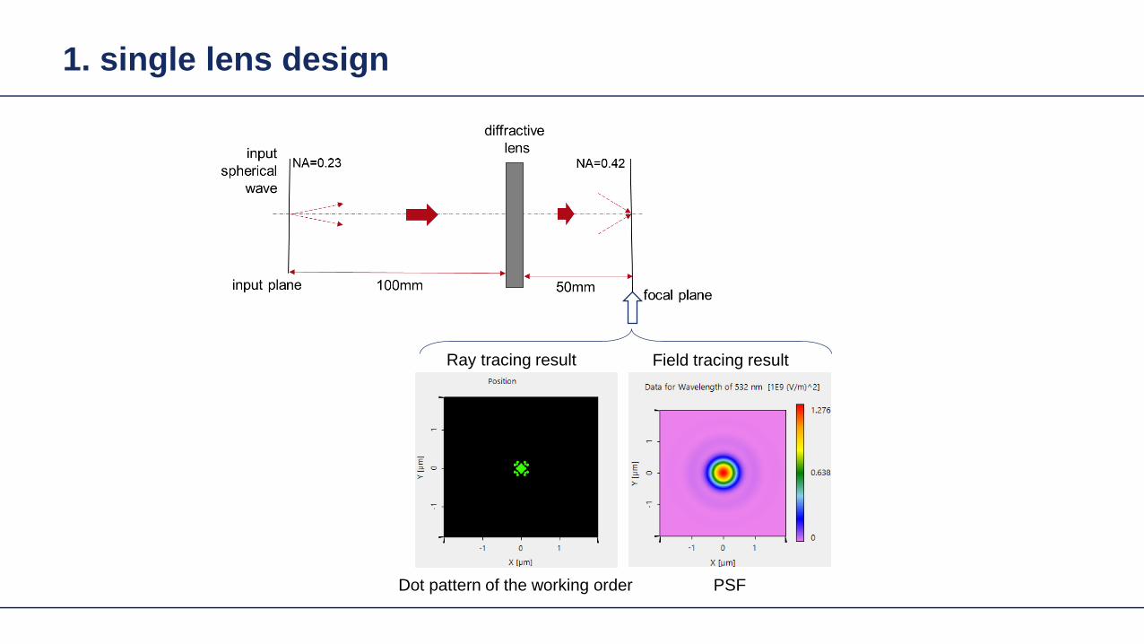

Example Focusing Lens wo Freeform
Size = 4227120583120583m
dot diagram PSF
Design Concept HOE and Freeform
Lens system 1
Target plane
SourceLens system
2
Signal field
FreeformHOE
Wavefront transformation (Aberration control)
Design Concept HOE and Freeform
Lens system 1
Target plane
SourceLens system
2
Signal fieldDesign step 1 Design in the functional embodimentbull Determination of phase in shaper plane Design step 2 Design in structural embodimentbull Design of HOE or refractive surface in order to
obtain the required phase change
FreeformHOE
Freeform Design Algorithm Example
Lens system 1
SourceLens system
2
Design step 1 Design in the functional embodimentInverse bull field propagation approach
Design step 2 Design in structural embodimentFast recursive design of freeform surface using bullspline interpolation approach based on full phase information (no parametric optimization)
FreeformTarget plane
Signal field
Example Focusing Lens wo Freeform
Size = 4227120583120583m
dot diagram PSF
Example Focusing Lens w Freeform
dot diagram
Size = 208120583120583m
PSFdot diagram PSF
Height Profile(3D view) Height Profile
(2D view)
Direct calculation without optimization in a few seconds
Result without correction with freeform surface
Example Focusing Lens Off-Axis
Freeform surface
3D view 2D view
Size = 076120583120583m
Size = 1279120583120583m
Result without correction with freeform surface
Example Focusing Lens Off-Axis
Freeform surface
3D view 2D view
dot diagram
Size = 076120583120583m
Size = 1279120583120583m
PSF
Direct calculation without optimization in a few seconds
Light Shaping Tasks Geometric Zones Only
Target in geometric field zone bull(GFZ)
bull Shaper in geometric field zone (GFZ)
Shaper Target
Light Shaping Tasks Geometric Zones Only
bull Functional designminus Propagation of field from DFZ into GFZminus Energy conservation leads to identity of
intergal over irradiances in shaper and target planes
minus Together with GFZ assumption phase can be designed
Light Shaping Tasks Geometric Zones Only
Functional designbullPropagation of field from DFZ into GFZminusEnergy conservation leads to identity of minusintergal over irradiances in shaper and target planes Together with GFZ assumption phase minuscan be designed
Light Shaping Tasks Geometric Zones Only
Functional designbullPropagation of field from DFZ into GFZminusEnergy conservation leads to identity of minusintergal over irradiances in shaper and target planes Together with GFZ assumption phase minuscan be designed
Light Shaping Tasks Geometric Zones Only
bull Functional designminus Propagation of field from DFZ into GFZminus Energy conservation leads to identity of
intergal over irradiances in shaper and target planes
minus Together with GFZ assumption phase can be designed
Proc SPIE 1998
Light Shaping Tasks Geometric Zones Only
bull Functional designminus Propagation of field from DFZ into GFZminus Energy conservation leads to identity of
intergal over irradiances in shaper and target planes
minus Together with GFZ assumption phase can be designed
2011
Gaussian to Top-Hat (Non-paraxial)
Gaussian wavehigh NA (001)
input plane
reference plane
target plane
target irradiance
30mm
35mm
35mm2m
m
2mm
20mm
the output NA asymp 04
The Rayleigh lengths of the input Gaussian is 5556microm
Gaussian to Top-Hat (Non-paraxial) Phase Design via Meshes
mesh on reference plane
2mm
2mm
30m
m
30mm
mesh on target plane
Gaussian wavehigh NA (001)
input plane
reference plane
target plane
30mm2mm
2mm
20mm
Gaussian to Top-Hat (Non-paraxial) Functional Embodiment
irradiance at target plane
cross-section (normalized)
Gaussian wavehigh NA (001)
input plane
functional embodiment
target plane
30mm2mm
2mm
20mm
irradiance before the component
irradiance after the component
Gaussian to Top-Hat (Non-paraxial) Functional Embodiment
irradiance at target plane
cross-section (normalized)
Gaussian wavehigh NA (001)
input plane
functional embodiment
target plane
30mm2mm
2mm
20mm
irradiance before the component
irradiance after the component
Resolution of pattern limited by GFZ assumption and NA of system
Light Shaping Tasks Geometric Zones Only
Structural design altrnativesbullFreeform surface design (convergent minusiterative algorithm)HOE design (direct design)minus
bull Functional designminus Propagation of field from DFZ into GFZminus Energy conservation leads to identity of
intergal over irradiances in shaper and target planes
minus Together with GFZ assumption phase can be designed
Gaussian to Top-Hat (Non-paraxial) Freeform Surface
irradiance behind the surface
irradiance at target planeGaussian wavehigh NA (001)
freeform element
target plane
30mm2mm
2mm
20mm
cross-section (normalized)
Height Profile(2D Contour line)
Elliptical Gaussian to Top-Hat (Non-paraxial) Freeform Surface
irradiance behind the surface
irradiance at target planeGaussian wavehigh NA (001)
input plane target
plane
30mm2mm
2mm
20mm
freeform element
cross-section (normalized)
Height Profile(2D Contour line)
Plane Wave to Far Field Pattern (Non-paraxial)
plane wave
input plane
optical element
target plane
target irradiance distribution
100mm
150mm
150mm
14mm
Plane Wave to Far Field Pattern (Non-paraxial) Functional Design
-75
0
-150
75
150mm
-75 0-150 75 150mm
0
-15
15mm
0-15 15mm
mesh on input plane
mesh on target plane
plane wave
input plane
referenceplane
target plane
100mm14mm
Plane Wave to Far Field Pattern (Non-paraxial) Functional
irradiance at target plane(normalized)
error from target irradiance
plane wave
input plane
functional component
target plane
100mm14mm
Resolution of pattern limited by GFZ assumption
Plane Wave to Far Field Pattern (Non-paraxial) Freeform Surface
ray tracing
irradiance at target plane(normalized)
error from target irradianceHeight Profile
(2D Contour line)
Gaussian to Top-Hat (Paraxial) Freeform Surface
Gaussian wavehigh NA (001)
input plane target
plane
300mm
2mm
2mm
20mm
freeformelement
irradiance behind the surface
irradiance at target plane
cross-section (normalized)
Height Profile(2D Contour line)
Field is in slow diffractive field zone
Gaussian to Top-Hat (Paraxial) Freeform Surface
bull Because of paraxial field (slow beams) shaper is in DFZ and not GFZ
bull That results in slight diffractive effects which are not included in design
bull By subsequent iterative Fourier transform algorithm which takes DFZ into account that can be corrected
Gaussian to Top-Hat (Non-paraxial) HOE
Gaussian wavehigh NA (001) HOE
target plane
30mm2mm
2mm
20mm
-1order 0 order +1order
irradiance behind HOE
the output NA asymp 04
Gaussian to Top-Hat (Non-paraxial) HOE
ray tracing result with HOE (with the working order of -1 order)
HOEinputplane
target plane
-1 order
HOEinputplane
target plane
0 order
HOEinputplane
target plane
+1 order
Investigate Rayleigh Coefficient
-1order 0 order +1order
Ex Component behind HOE
cross-section profile result from Grating Toolbox
-1 o
rder
0 or
der
+1 o
rder
the Rayleight coefficient along the cross-section is compared with the result from Grating Toolbox
Modeling with Fourier Modal Method (FMM)
Gaussian to Top-Hat (Non-paraxial) HOE
Gaussian wavehigh NA (001) HOE
target plane
30mm2mm
2mm
20mm
-1order 0 order +1order
irradiance on target plane
Gaussian to Top-Hat (Non-paraxial) Lens + HOE
Gaussian wavehigh NA (001)
HOE target plane
30mm2mm
2mm
20mm
sphericallens
Gaussian to Top-Hat (Non-paraxial) Lens + HOE
Gaussian wavehigh NA (001)
HOE target plane
30mm2mm
2mm
20mm
sphericallens
wavefront behind spherical lens
the Peak-to-Valley wavefront error is 3583120582120582
wavefront error with respect to spherical wavefront
Gaussian to Top-Hat (Non-paraxial) Lens + HOE
The result irradiance on target plane is compared with the previous case without the lens
-1order 0 order +1order
without the lens
with the lens
Light Shaping Tasks Cases
Target in geometric field zone bull(GFZ)
bull Shaper in geometric field zone (GFZ)
Shaper Target
Light Shaping Tasks Gaussian to RingmodeShaper Target
Gaussian to Ringmode Refractive Approach (GFZ)Shaper Target
Gaussian to Ringmode Refractive Approach (GFZ)Shaper Target
Gaussian to Ringmode Diffractive Approach (DFZ)Vortex + Lens Target
DFZ
Gaussian to Ringmode Diffractive Approach (DFZ)Vortex + Lens Target
Diffractive light shaping by coherent superposition
Diffractive beam splitter and diffuser
Shaping by ldquoBeam ScanningrdquoTarget
Basic source mode eg Gaussian
Shaping by ldquoBeam Scanningrdquo
bull Beam splits at shaperbull Field behind shaper is in diffractive field zonebull Shaper is grating DOE
Shaper Target
Target pattern is ldquowrittenrdquo by scanned beam in target plane
Illustration of Deflection
Phase of transmission Intensity in target
Illustration of Deflection
Phase of transmission Intensity in target
Illustration of Deflection
Phase of transmission Intensity in target
Illustration of Deflection
Phase of transmission Intensity in target
Illustration of Deflection
Phase of transmission Intensity in target
Illustration of Deflection Sum
Phase of transmission Intensity in target
Basic Design Situations Splitting
bull Spots overlap in target patten diffractive diffuser
bull Spots in target pattern do not overlap diffractive beam splitter
Basic Design Situations Splitting
bull Spots overlap in target patten diffractive diffuser
Spots in target pattern do not bulloverlap diffractive beam splitter
Shaping by ldquoBeam Scanningrdquo
Amplitude Phase
Iterative Fourier Transform Algorithm
Advanced diffractive optics design techniques
Design technique (IFTA) implemented in VirtualLabtrade
Micro-structured surface profile
Fabricated at IAP University of Jena
Feature Sizes of Element
Feature sizeabout 400 nm
4 height levels
Optical Experiment
Jenaacutes sbquoSkylinelsquo
Comments on Diffuser Technology
Very flexible in light pattern generationbullRobust against adjustment problems bullCoherent light leads to speckle patternbullSize of speckle features can be adjusted by focusing systembullDiffusers work for partially coherent beams bullPartially coherent beams smooth the speckle pattern effect can be simulated bullwith VirtualLabtrade
Diffractive Optics Pattern Generation
Diffuser technology
Diffractive Optics Pattern Generation
Diffuser technology Design very chromatic
Source RGB
Solution by Integrated Diffractive Optics
wwwLightTranscom112
Far Field Propagation
Source Plane Wave RGB Transmission Regions
Waveguide Component
High NA Beam Splitter by Two DOElsquos
Parameter Value amp Unitnumber of orders 11 x 11order separation 1 x 1 degperiod 3035 x 3035 micrompixel size 690 x 690 nmdiscrete height levels 8material fused silica
surfaceprofile
paraxial beam splitter
Specification Second Beam Splitter
Parameter Value amp Unitnumber of orders 5 x 5order separation 11 x 11 degperiod 273 x 273 micrompixel size 130 x 130 nmdiscrete height levels 8material fused silica
surfaceprofile
high-NA beam splitter
Results Spot Diagram
spot diagram
combination of both beam splitter generate 55 x 55 order with 55x 55deg full
opening spread
a
Results Output Evaluation with FMM
Light shaping by lateral decomposition
Elementary cell array components
Array of Deflectors
Array of Deflectors
Deflection can be done by gratings prisms mirrors
TaskSystem Illustration
Cell Array Element
spherical wave(point source)
cell array structurebuilt up withbull prismsbull gratingsbull mirrors
Parameter Description Value amp Unittype RGB LEDemitter size 100 x 100 micromwavelength (473 532 635) nmpolarization right circularly polarized lightnumber of lateral modes 3 x 3Total number of lateral andspectral modes
27
Specification Light Source
Specification Cell Array
Parameter Value amp Unitnumber of cells 100 x 100cell size 125 x 125 micromarray aperture 125 x 125 mm
Results 3D System Ray Tracing
Results Grating Cells Array
spot
dia
gram
inte
nsity
pat
tern
(re
al c
olor
vie
w)
for grating cells array strong dispersion
effects occur
Results Prism Cells Array
spot
dia
gram
inte
nsity
pat
tern
(re
al c
olor
vie
w)
the dispersion is significantly reduced by
using prisms
Results Mirror Cells Array
spot
dia
gram
inte
nsity
pat
tern
(re
al c
olor
vie
w)
due to reflective approach no dispersion
effects occur
Light shaping by lateral decomposition
Lens and freeform array components
Array of Micro-optical Components
Lateral combination of elementary light shaping solutions
TaskSystem Illustration
50 mm Angular Spectrum (Far Field)
LED + collimation optic
aperiodic refractive beam shaper array (aBSA)
camera detector
Specs Light Source
spectrum model
fast and accurate modeling of a white bulllight LEDdesign and analysis an aperiodic bullrefractive beam shaper array to optimize a top hat intensity pattern
Highlightshere
Results Intensity Pattern (real color view)
aperiodic beam shaper array periodic microlens array
a
Summary
Introduction of a geometric branch of physical optics bullwith the help of the geometric Fourier transform Refractive and diffractive light shaping concepts bullfollow a unified theory in physical optics Classification of light shaping concepts dependent of bullpositions of shaper(s) and target in field zones Elementary shaping concepts can be combinedbull
Superposition in same area eg beam splitterminusLaterally combined eg cell arrayminus -type components
Further investigations on the basis of the unified bulltheory will reveal further concepts and deeper understanding of light shaping
bull Designs and simulations done with VirtualLab Fusion software

Design Concept HOE and Freeform
Lens system 1
Target plane
SourceLens system
2
Signal field
FreeformHOE
Wavefront transformation (Aberration control)
Design Concept HOE and Freeform
Lens system 1
Target plane
SourceLens system
2
Signal fieldDesign step 1 Design in the functional embodimentbull Determination of phase in shaper plane Design step 2 Design in structural embodimentbull Design of HOE or refractive surface in order to
obtain the required phase change
FreeformHOE
Freeform Design Algorithm Example
Lens system 1
SourceLens system
2
Design step 1 Design in the functional embodimentInverse bull field propagation approach
Design step 2 Design in structural embodimentFast recursive design of freeform surface using bullspline interpolation approach based on full phase information (no parametric optimization)
FreeformTarget plane
Signal field
Example Focusing Lens wo Freeform
Size = 4227120583120583m
dot diagram PSF
Example Focusing Lens w Freeform
dot diagram
Size = 208120583120583m
PSFdot diagram PSF
Height Profile(3D view) Height Profile
(2D view)
Direct calculation without optimization in a few seconds
Result without correction with freeform surface
Example Focusing Lens Off-Axis
Freeform surface
3D view 2D view
Size = 076120583120583m
Size = 1279120583120583m
Result without correction with freeform surface
Example Focusing Lens Off-Axis
Freeform surface
3D view 2D view
dot diagram
Size = 076120583120583m
Size = 1279120583120583m
PSF
Direct calculation without optimization in a few seconds
Light Shaping Tasks Geometric Zones Only
Target in geometric field zone bull(GFZ)
bull Shaper in geometric field zone (GFZ)
Shaper Target
Light Shaping Tasks Geometric Zones Only
bull Functional designminus Propagation of field from DFZ into GFZminus Energy conservation leads to identity of
intergal over irradiances in shaper and target planes
minus Together with GFZ assumption phase can be designed
Light Shaping Tasks Geometric Zones Only
Functional designbullPropagation of field from DFZ into GFZminusEnergy conservation leads to identity of minusintergal over irradiances in shaper and target planes Together with GFZ assumption phase minuscan be designed
Light Shaping Tasks Geometric Zones Only
Functional designbullPropagation of field from DFZ into GFZminusEnergy conservation leads to identity of minusintergal over irradiances in shaper and target planes Together with GFZ assumption phase minuscan be designed
Light Shaping Tasks Geometric Zones Only
bull Functional designminus Propagation of field from DFZ into GFZminus Energy conservation leads to identity of
intergal over irradiances in shaper and target planes
minus Together with GFZ assumption phase can be designed
Proc SPIE 1998
Light Shaping Tasks Geometric Zones Only
bull Functional designminus Propagation of field from DFZ into GFZminus Energy conservation leads to identity of
intergal over irradiances in shaper and target planes
minus Together with GFZ assumption phase can be designed
2011
Gaussian to Top-Hat (Non-paraxial)
Gaussian wavehigh NA (001)
input plane
reference plane
target plane
target irradiance
30mm
35mm
35mm2m
m
2mm
20mm
the output NA asymp 04
The Rayleigh lengths of the input Gaussian is 5556microm
Gaussian to Top-Hat (Non-paraxial) Phase Design via Meshes
mesh on reference plane
2mm
2mm
30m
m
30mm
mesh on target plane
Gaussian wavehigh NA (001)
input plane
reference plane
target plane
30mm2mm
2mm
20mm
Gaussian to Top-Hat (Non-paraxial) Functional Embodiment
irradiance at target plane
cross-section (normalized)
Gaussian wavehigh NA (001)
input plane
functional embodiment
target plane
30mm2mm
2mm
20mm
irradiance before the component
irradiance after the component
Gaussian to Top-Hat (Non-paraxial) Functional Embodiment
irradiance at target plane
cross-section (normalized)
Gaussian wavehigh NA (001)
input plane
functional embodiment
target plane
30mm2mm
2mm
20mm
irradiance before the component
irradiance after the component
Resolution of pattern limited by GFZ assumption and NA of system
Light Shaping Tasks Geometric Zones Only
Structural design altrnativesbullFreeform surface design (convergent minusiterative algorithm)HOE design (direct design)minus
bull Functional designminus Propagation of field from DFZ into GFZminus Energy conservation leads to identity of
intergal over irradiances in shaper and target planes
minus Together with GFZ assumption phase can be designed
Gaussian to Top-Hat (Non-paraxial) Freeform Surface
irradiance behind the surface
irradiance at target planeGaussian wavehigh NA (001)
freeform element
target plane
30mm2mm
2mm
20mm
cross-section (normalized)
Height Profile(2D Contour line)
Elliptical Gaussian to Top-Hat (Non-paraxial) Freeform Surface
irradiance behind the surface
irradiance at target planeGaussian wavehigh NA (001)
input plane target
plane
30mm2mm
2mm
20mm
freeform element
cross-section (normalized)
Height Profile(2D Contour line)
Plane Wave to Far Field Pattern (Non-paraxial)
plane wave
input plane
optical element
target plane
target irradiance distribution
100mm
150mm
150mm
14mm
Plane Wave to Far Field Pattern (Non-paraxial) Functional Design
-75
0
-150
75
150mm
-75 0-150 75 150mm
0
-15
15mm
0-15 15mm
mesh on input plane
mesh on target plane
plane wave
input plane
referenceplane
target plane
100mm14mm
Plane Wave to Far Field Pattern (Non-paraxial) Functional
irradiance at target plane(normalized)
error from target irradiance
plane wave
input plane
functional component
target plane
100mm14mm
Resolution of pattern limited by GFZ assumption
Plane Wave to Far Field Pattern (Non-paraxial) Freeform Surface
ray tracing
irradiance at target plane(normalized)
error from target irradianceHeight Profile
(2D Contour line)
Gaussian to Top-Hat (Paraxial) Freeform Surface
Gaussian wavehigh NA (001)
input plane target
plane
300mm
2mm
2mm
20mm
freeformelement
irradiance behind the surface
irradiance at target plane
cross-section (normalized)
Height Profile(2D Contour line)
Field is in slow diffractive field zone
Gaussian to Top-Hat (Paraxial) Freeform Surface
bull Because of paraxial field (slow beams) shaper is in DFZ and not GFZ
bull That results in slight diffractive effects which are not included in design
bull By subsequent iterative Fourier transform algorithm which takes DFZ into account that can be corrected
Gaussian to Top-Hat (Non-paraxial) HOE
Gaussian wavehigh NA (001) HOE
target plane
30mm2mm
2mm
20mm
-1order 0 order +1order
irradiance behind HOE
the output NA asymp 04
Gaussian to Top-Hat (Non-paraxial) HOE
ray tracing result with HOE (with the working order of -1 order)
HOEinputplane
target plane
-1 order
HOEinputplane
target plane
0 order
HOEinputplane
target plane
+1 order
Investigate Rayleigh Coefficient
-1order 0 order +1order
Ex Component behind HOE
cross-section profile result from Grating Toolbox
-1 o
rder
0 or
der
+1 o
rder
the Rayleight coefficient along the cross-section is compared with the result from Grating Toolbox
Modeling with Fourier Modal Method (FMM)
Gaussian to Top-Hat (Non-paraxial) HOE
Gaussian wavehigh NA (001) HOE
target plane
30mm2mm
2mm
20mm
-1order 0 order +1order
irradiance on target plane
Gaussian to Top-Hat (Non-paraxial) Lens + HOE
Gaussian wavehigh NA (001)
HOE target plane
30mm2mm
2mm
20mm
sphericallens
Gaussian to Top-Hat (Non-paraxial) Lens + HOE
Gaussian wavehigh NA (001)
HOE target plane
30mm2mm
2mm
20mm
sphericallens
wavefront behind spherical lens
the Peak-to-Valley wavefront error is 3583120582120582
wavefront error with respect to spherical wavefront
Gaussian to Top-Hat (Non-paraxial) Lens + HOE
The result irradiance on target plane is compared with the previous case without the lens
-1order 0 order +1order
without the lens
with the lens
Light Shaping Tasks Cases
Target in geometric field zone bull(GFZ)
bull Shaper in geometric field zone (GFZ)
Shaper Target
Light Shaping Tasks Gaussian to RingmodeShaper Target
Gaussian to Ringmode Refractive Approach (GFZ)Shaper Target
Gaussian to Ringmode Refractive Approach (GFZ)Shaper Target
Gaussian to Ringmode Diffractive Approach (DFZ)Vortex + Lens Target
DFZ
Gaussian to Ringmode Diffractive Approach (DFZ)Vortex + Lens Target
Diffractive light shaping by coherent superposition
Diffractive beam splitter and diffuser
Shaping by ldquoBeam ScanningrdquoTarget
Basic source mode eg Gaussian
Shaping by ldquoBeam Scanningrdquo
bull Beam splits at shaperbull Field behind shaper is in diffractive field zonebull Shaper is grating DOE
Shaper Target
Target pattern is ldquowrittenrdquo by scanned beam in target plane
Illustration of Deflection
Phase of transmission Intensity in target
Illustration of Deflection
Phase of transmission Intensity in target
Illustration of Deflection
Phase of transmission Intensity in target
Illustration of Deflection
Phase of transmission Intensity in target
Illustration of Deflection
Phase of transmission Intensity in target
Illustration of Deflection Sum
Phase of transmission Intensity in target
Basic Design Situations Splitting
bull Spots overlap in target patten diffractive diffuser
bull Spots in target pattern do not overlap diffractive beam splitter
Basic Design Situations Splitting
bull Spots overlap in target patten diffractive diffuser
Spots in target pattern do not bulloverlap diffractive beam splitter
Shaping by ldquoBeam Scanningrdquo
Amplitude Phase
Iterative Fourier Transform Algorithm
Advanced diffractive optics design techniques
Design technique (IFTA) implemented in VirtualLabtrade
Micro-structured surface profile
Fabricated at IAP University of Jena
Feature Sizes of Element
Feature sizeabout 400 nm
4 height levels
Optical Experiment
Jenaacutes sbquoSkylinelsquo
Comments on Diffuser Technology
Very flexible in light pattern generationbullRobust against adjustment problems bullCoherent light leads to speckle patternbullSize of speckle features can be adjusted by focusing systembullDiffusers work for partially coherent beams bullPartially coherent beams smooth the speckle pattern effect can be simulated bullwith VirtualLabtrade
Diffractive Optics Pattern Generation
Diffuser technology
Diffractive Optics Pattern Generation
Diffuser technology Design very chromatic
Source RGB
Solution by Integrated Diffractive Optics
wwwLightTranscom112
Far Field Propagation
Source Plane Wave RGB Transmission Regions
Waveguide Component
High NA Beam Splitter by Two DOElsquos
Parameter Value amp Unitnumber of orders 11 x 11order separation 1 x 1 degperiod 3035 x 3035 micrompixel size 690 x 690 nmdiscrete height levels 8material fused silica
surfaceprofile
paraxial beam splitter
Specification Second Beam Splitter
Parameter Value amp Unitnumber of orders 5 x 5order separation 11 x 11 degperiod 273 x 273 micrompixel size 130 x 130 nmdiscrete height levels 8material fused silica
surfaceprofile
high-NA beam splitter
Results Spot Diagram
spot diagram
combination of both beam splitter generate 55 x 55 order with 55x 55deg full
opening spread
a
Results Output Evaluation with FMM
Light shaping by lateral decomposition
Elementary cell array components
Array of Deflectors
Array of Deflectors
Deflection can be done by gratings prisms mirrors
TaskSystem Illustration
Cell Array Element
spherical wave(point source)
cell array structurebuilt up withbull prismsbull gratingsbull mirrors
Parameter Description Value amp Unittype RGB LEDemitter size 100 x 100 micromwavelength (473 532 635) nmpolarization right circularly polarized lightnumber of lateral modes 3 x 3Total number of lateral andspectral modes
27
Specification Light Source
Specification Cell Array
Parameter Value amp Unitnumber of cells 100 x 100cell size 125 x 125 micromarray aperture 125 x 125 mm
Results 3D System Ray Tracing
Results Grating Cells Array
spot
dia
gram
inte
nsity
pat
tern
(re
al c
olor
vie
w)
for grating cells array strong dispersion
effects occur
Results Prism Cells Array
spot
dia
gram
inte
nsity
pat
tern
(re
al c
olor
vie
w)
the dispersion is significantly reduced by
using prisms
Results Mirror Cells Array
spot
dia
gram
inte
nsity
pat
tern
(re
al c
olor
vie
w)
due to reflective approach no dispersion
effects occur
Light shaping by lateral decomposition
Lens and freeform array components
Array of Micro-optical Components
Lateral combination of elementary light shaping solutions
TaskSystem Illustration
50 mm Angular Spectrum (Far Field)
LED + collimation optic
aperiodic refractive beam shaper array (aBSA)
camera detector
Specs Light Source
spectrum model
fast and accurate modeling of a white bulllight LEDdesign and analysis an aperiodic bullrefractive beam shaper array to optimize a top hat intensity pattern
Highlightshere
Results Intensity Pattern (real color view)
aperiodic beam shaper array periodic microlens array
a
Summary
Introduction of a geometric branch of physical optics bullwith the help of the geometric Fourier transform Refractive and diffractive light shaping concepts bullfollow a unified theory in physical optics Classification of light shaping concepts dependent of bullpositions of shaper(s) and target in field zones Elementary shaping concepts can be combinedbull
Superposition in same area eg beam splitterminusLaterally combined eg cell arrayminus -type components
Further investigations on the basis of the unified bulltheory will reveal further concepts and deeper understanding of light shaping
bull Designs and simulations done with VirtualLab Fusion software

Design Concept HOE and Freeform
Lens system 1
Target plane
SourceLens system
2
Signal fieldDesign step 1 Design in the functional embodimentbull Determination of phase in shaper plane Design step 2 Design in structural embodimentbull Design of HOE or refractive surface in order to
obtain the required phase change
FreeformHOE
Freeform Design Algorithm Example
Lens system 1
SourceLens system
2
Design step 1 Design in the functional embodimentInverse bull field propagation approach
Design step 2 Design in structural embodimentFast recursive design of freeform surface using bullspline interpolation approach based on full phase information (no parametric optimization)
FreeformTarget plane
Signal field
Example Focusing Lens wo Freeform
Size = 4227120583120583m
dot diagram PSF
Example Focusing Lens w Freeform
dot diagram
Size = 208120583120583m
PSFdot diagram PSF
Height Profile(3D view) Height Profile
(2D view)
Direct calculation without optimization in a few seconds
Result without correction with freeform surface
Example Focusing Lens Off-Axis
Freeform surface
3D view 2D view
Size = 076120583120583m
Size = 1279120583120583m
Result without correction with freeform surface
Example Focusing Lens Off-Axis
Freeform surface
3D view 2D view
dot diagram
Size = 076120583120583m
Size = 1279120583120583m
PSF
Direct calculation without optimization in a few seconds
Light Shaping Tasks Geometric Zones Only
Target in geometric field zone bull(GFZ)
bull Shaper in geometric field zone (GFZ)
Shaper Target
Light Shaping Tasks Geometric Zones Only
bull Functional designminus Propagation of field from DFZ into GFZminus Energy conservation leads to identity of
intergal over irradiances in shaper and target planes
minus Together with GFZ assumption phase can be designed
Light Shaping Tasks Geometric Zones Only
Functional designbullPropagation of field from DFZ into GFZminusEnergy conservation leads to identity of minusintergal over irradiances in shaper and target planes Together with GFZ assumption phase minuscan be designed
Light Shaping Tasks Geometric Zones Only
Functional designbullPropagation of field from DFZ into GFZminusEnergy conservation leads to identity of minusintergal over irradiances in shaper and target planes Together with GFZ assumption phase minuscan be designed
Light Shaping Tasks Geometric Zones Only
bull Functional designminus Propagation of field from DFZ into GFZminus Energy conservation leads to identity of
intergal over irradiances in shaper and target planes
minus Together with GFZ assumption phase can be designed
Proc SPIE 1998
Light Shaping Tasks Geometric Zones Only
bull Functional designminus Propagation of field from DFZ into GFZminus Energy conservation leads to identity of
intergal over irradiances in shaper and target planes
minus Together with GFZ assumption phase can be designed
2011
Gaussian to Top-Hat (Non-paraxial)
Gaussian wavehigh NA (001)
input plane
reference plane
target plane
target irradiance
30mm
35mm
35mm2m
m
2mm
20mm
the output NA asymp 04
The Rayleigh lengths of the input Gaussian is 5556microm
Gaussian to Top-Hat (Non-paraxial) Phase Design via Meshes
mesh on reference plane
2mm
2mm
30m
m
30mm
mesh on target plane
Gaussian wavehigh NA (001)
input plane
reference plane
target plane
30mm2mm
2mm
20mm
Gaussian to Top-Hat (Non-paraxial) Functional Embodiment
irradiance at target plane
cross-section (normalized)
Gaussian wavehigh NA (001)
input plane
functional embodiment
target plane
30mm2mm
2mm
20mm
irradiance before the component
irradiance after the component
Gaussian to Top-Hat (Non-paraxial) Functional Embodiment
irradiance at target plane
cross-section (normalized)
Gaussian wavehigh NA (001)
input plane
functional embodiment
target plane
30mm2mm
2mm
20mm
irradiance before the component
irradiance after the component
Resolution of pattern limited by GFZ assumption and NA of system
Light Shaping Tasks Geometric Zones Only
Structural design altrnativesbullFreeform surface design (convergent minusiterative algorithm)HOE design (direct design)minus
bull Functional designminus Propagation of field from DFZ into GFZminus Energy conservation leads to identity of
intergal over irradiances in shaper and target planes
minus Together with GFZ assumption phase can be designed
Gaussian to Top-Hat (Non-paraxial) Freeform Surface
irradiance behind the surface
irradiance at target planeGaussian wavehigh NA (001)
freeform element
target plane
30mm2mm
2mm
20mm
cross-section (normalized)
Height Profile(2D Contour line)
Elliptical Gaussian to Top-Hat (Non-paraxial) Freeform Surface
irradiance behind the surface
irradiance at target planeGaussian wavehigh NA (001)
input plane target
plane
30mm2mm
2mm
20mm
freeform element
cross-section (normalized)
Height Profile(2D Contour line)
Plane Wave to Far Field Pattern (Non-paraxial)
plane wave
input plane
optical element
target plane
target irradiance distribution
100mm
150mm
150mm
14mm
Plane Wave to Far Field Pattern (Non-paraxial) Functional Design
-75
0
-150
75
150mm
-75 0-150 75 150mm
0
-15
15mm
0-15 15mm
mesh on input plane
mesh on target plane
plane wave
input plane
referenceplane
target plane
100mm14mm
Plane Wave to Far Field Pattern (Non-paraxial) Functional
irradiance at target plane(normalized)
error from target irradiance
plane wave
input plane
functional component
target plane
100mm14mm
Resolution of pattern limited by GFZ assumption
Plane Wave to Far Field Pattern (Non-paraxial) Freeform Surface
ray tracing
irradiance at target plane(normalized)
error from target irradianceHeight Profile
(2D Contour line)
Gaussian to Top-Hat (Paraxial) Freeform Surface
Gaussian wavehigh NA (001)
input plane target
plane
300mm
2mm
2mm
20mm
freeformelement
irradiance behind the surface
irradiance at target plane
cross-section (normalized)
Height Profile(2D Contour line)
Field is in slow diffractive field zone
Gaussian to Top-Hat (Paraxial) Freeform Surface
bull Because of paraxial field (slow beams) shaper is in DFZ and not GFZ
bull That results in slight diffractive effects which are not included in design
bull By subsequent iterative Fourier transform algorithm which takes DFZ into account that can be corrected
Gaussian to Top-Hat (Non-paraxial) HOE
Gaussian wavehigh NA (001) HOE
target plane
30mm2mm
2mm
20mm
-1order 0 order +1order
irradiance behind HOE
the output NA asymp 04
Gaussian to Top-Hat (Non-paraxial) HOE
ray tracing result with HOE (with the working order of -1 order)
HOEinputplane
target plane
-1 order
HOEinputplane
target plane
0 order
HOEinputplane
target plane
+1 order
Investigate Rayleigh Coefficient
-1order 0 order +1order
Ex Component behind HOE
cross-section profile result from Grating Toolbox
-1 o
rder
0 or
der
+1 o
rder
the Rayleight coefficient along the cross-section is compared with the result from Grating Toolbox
Modeling with Fourier Modal Method (FMM)
Gaussian to Top-Hat (Non-paraxial) HOE
Gaussian wavehigh NA (001) HOE
target plane
30mm2mm
2mm
20mm
-1order 0 order +1order
irradiance on target plane
Gaussian to Top-Hat (Non-paraxial) Lens + HOE
Gaussian wavehigh NA (001)
HOE target plane
30mm2mm
2mm
20mm
sphericallens
Gaussian to Top-Hat (Non-paraxial) Lens + HOE
Gaussian wavehigh NA (001)
HOE target plane
30mm2mm
2mm
20mm
sphericallens
wavefront behind spherical lens
the Peak-to-Valley wavefront error is 3583120582120582
wavefront error with respect to spherical wavefront
Gaussian to Top-Hat (Non-paraxial) Lens + HOE
The result irradiance on target plane is compared with the previous case without the lens
-1order 0 order +1order
without the lens
with the lens
Light Shaping Tasks Cases
Target in geometric field zone bull(GFZ)
bull Shaper in geometric field zone (GFZ)
Shaper Target
Light Shaping Tasks Gaussian to RingmodeShaper Target
Gaussian to Ringmode Refractive Approach (GFZ)Shaper Target
Gaussian to Ringmode Refractive Approach (GFZ)Shaper Target
Gaussian to Ringmode Diffractive Approach (DFZ)Vortex + Lens Target
DFZ
Gaussian to Ringmode Diffractive Approach (DFZ)Vortex + Lens Target
Diffractive light shaping by coherent superposition
Diffractive beam splitter and diffuser
Shaping by ldquoBeam ScanningrdquoTarget
Basic source mode eg Gaussian
Shaping by ldquoBeam Scanningrdquo
bull Beam splits at shaperbull Field behind shaper is in diffractive field zonebull Shaper is grating DOE
Shaper Target
Target pattern is ldquowrittenrdquo by scanned beam in target plane
Illustration of Deflection
Phase of transmission Intensity in target
Illustration of Deflection
Phase of transmission Intensity in target
Illustration of Deflection
Phase of transmission Intensity in target
Illustration of Deflection
Phase of transmission Intensity in target
Illustration of Deflection
Phase of transmission Intensity in target
Illustration of Deflection Sum
Phase of transmission Intensity in target
Basic Design Situations Splitting
bull Spots overlap in target patten diffractive diffuser
bull Spots in target pattern do not overlap diffractive beam splitter
Basic Design Situations Splitting
bull Spots overlap in target patten diffractive diffuser
Spots in target pattern do not bulloverlap diffractive beam splitter
Shaping by ldquoBeam Scanningrdquo
Amplitude Phase
Iterative Fourier Transform Algorithm
Advanced diffractive optics design techniques
Design technique (IFTA) implemented in VirtualLabtrade
Micro-structured surface profile
Fabricated at IAP University of Jena
Feature Sizes of Element
Feature sizeabout 400 nm
4 height levels
Optical Experiment
Jenaacutes sbquoSkylinelsquo
Comments on Diffuser Technology
Very flexible in light pattern generationbullRobust against adjustment problems bullCoherent light leads to speckle patternbullSize of speckle features can be adjusted by focusing systembullDiffusers work for partially coherent beams bullPartially coherent beams smooth the speckle pattern effect can be simulated bullwith VirtualLabtrade
Diffractive Optics Pattern Generation
Diffuser technology
Diffractive Optics Pattern Generation
Diffuser technology Design very chromatic
Source RGB
Solution by Integrated Diffractive Optics
wwwLightTranscom112
Far Field Propagation
Source Plane Wave RGB Transmission Regions
Waveguide Component
High NA Beam Splitter by Two DOElsquos
Parameter Value amp Unitnumber of orders 11 x 11order separation 1 x 1 degperiod 3035 x 3035 micrompixel size 690 x 690 nmdiscrete height levels 8material fused silica
surfaceprofile
paraxial beam splitter
Specification Second Beam Splitter
Parameter Value amp Unitnumber of orders 5 x 5order separation 11 x 11 degperiod 273 x 273 micrompixel size 130 x 130 nmdiscrete height levels 8material fused silica
surfaceprofile
high-NA beam splitter
Results Spot Diagram
spot diagram
combination of both beam splitter generate 55 x 55 order with 55x 55deg full
opening spread
a
Results Output Evaluation with FMM
Light shaping by lateral decomposition
Elementary cell array components
Array of Deflectors
Array of Deflectors
Deflection can be done by gratings prisms mirrors
TaskSystem Illustration
Cell Array Element
spherical wave(point source)
cell array structurebuilt up withbull prismsbull gratingsbull mirrors
Parameter Description Value amp Unittype RGB LEDemitter size 100 x 100 micromwavelength (473 532 635) nmpolarization right circularly polarized lightnumber of lateral modes 3 x 3Total number of lateral andspectral modes
27
Specification Light Source
Specification Cell Array
Parameter Value amp Unitnumber of cells 100 x 100cell size 125 x 125 micromarray aperture 125 x 125 mm
Results 3D System Ray Tracing
Results Grating Cells Array
spot
dia
gram
inte
nsity
pat
tern
(re
al c
olor
vie
w)
for grating cells array strong dispersion
effects occur
Results Prism Cells Array
spot
dia
gram
inte
nsity
pat
tern
(re
al c
olor
vie
w)
the dispersion is significantly reduced by
using prisms
Results Mirror Cells Array
spot
dia
gram
inte
nsity
pat
tern
(re
al c
olor
vie
w)
due to reflective approach no dispersion
effects occur
Light shaping by lateral decomposition
Lens and freeform array components
Array of Micro-optical Components
Lateral combination of elementary light shaping solutions
TaskSystem Illustration
50 mm Angular Spectrum (Far Field)
LED + collimation optic
aperiodic refractive beam shaper array (aBSA)
camera detector
Specs Light Source
spectrum model
fast and accurate modeling of a white bulllight LEDdesign and analysis an aperiodic bullrefractive beam shaper array to optimize a top hat intensity pattern
Highlightshere
Results Intensity Pattern (real color view)
aperiodic beam shaper array periodic microlens array
a
Summary
Introduction of a geometric branch of physical optics bullwith the help of the geometric Fourier transform Refractive and diffractive light shaping concepts bullfollow a unified theory in physical optics Classification of light shaping concepts dependent of bullpositions of shaper(s) and target in field zones Elementary shaping concepts can be combinedbull
Superposition in same area eg beam splitterminusLaterally combined eg cell arrayminus -type components
Further investigations on the basis of the unified bulltheory will reveal further concepts and deeper understanding of light shaping
bull Designs and simulations done with VirtualLab Fusion software

Example Focusing Lens Off-Axis
Freeform surface
3D view 2D view
Size = 076120583120583m
Size = 1279120583120583m
Result without correction with freeform surface
Example Focusing Lens Off-Axis
Freeform surface
3D view 2D view
dot diagram
Size = 076120583120583m
Size = 1279120583120583m
PSF
Direct calculation without optimization in a few seconds
Light Shaping Tasks Geometric Zones Only
Target in geometric field zone bull(GFZ)
bull Shaper in geometric field zone (GFZ)
Shaper Target
Light Shaping Tasks Geometric Zones Only
bull Functional designminus Propagation of field from DFZ into GFZminus Energy conservation leads to identity of
intergal over irradiances in shaper and target planes
minus Together with GFZ assumption phase can be designed
Light Shaping Tasks Geometric Zones Only
Functional designbullPropagation of field from DFZ into GFZminusEnergy conservation leads to identity of minusintergal over irradiances in shaper and target planes Together with GFZ assumption phase minuscan be designed
Light Shaping Tasks Geometric Zones Only
Functional designbullPropagation of field from DFZ into GFZminusEnergy conservation leads to identity of minusintergal over irradiances in shaper and target planes Together with GFZ assumption phase minuscan be designed
Light Shaping Tasks Geometric Zones Only
bull Functional designminus Propagation of field from DFZ into GFZminus Energy conservation leads to identity of
intergal over irradiances in shaper and target planes
minus Together with GFZ assumption phase can be designed
Proc SPIE 1998
Light Shaping Tasks Geometric Zones Only
bull Functional designminus Propagation of field from DFZ into GFZminus Energy conservation leads to identity of
intergal over irradiances in shaper and target planes
minus Together with GFZ assumption phase can be designed
2011
Gaussian to Top-Hat (Non-paraxial)
Gaussian wavehigh NA (001)
input plane
reference plane
target plane
target irradiance
30mm
35mm
35mm2m
m
2mm
20mm
the output NA asymp 04
The Rayleigh lengths of the input Gaussian is 5556microm
Gaussian to Top-Hat (Non-paraxial) Phase Design via Meshes
mesh on reference plane
2mm
2mm
30m
m
30mm
mesh on target plane
Gaussian wavehigh NA (001)
input plane
reference plane
target plane
30mm2mm
2mm
20mm
Gaussian to Top-Hat (Non-paraxial) Functional Embodiment
irradiance at target plane
cross-section (normalized)
Gaussian wavehigh NA (001)
input plane
functional embodiment
target plane
30mm2mm
2mm
20mm
irradiance before the component
irradiance after the component
Gaussian to Top-Hat (Non-paraxial) Functional Embodiment
irradiance at target plane
cross-section (normalized)
Gaussian wavehigh NA (001)
input plane
functional embodiment
target plane
30mm2mm
2mm
20mm
irradiance before the component
irradiance after the component
Resolution of pattern limited by GFZ assumption and NA of system
Light Shaping Tasks Geometric Zones Only
Structural design altrnativesbullFreeform surface design (convergent minusiterative algorithm)HOE design (direct design)minus
bull Functional designminus Propagation of field from DFZ into GFZminus Energy conservation leads to identity of
intergal over irradiances in shaper and target planes
minus Together with GFZ assumption phase can be designed
Gaussian to Top-Hat (Non-paraxial) Freeform Surface
irradiance behind the surface
irradiance at target planeGaussian wavehigh NA (001)
freeform element
target plane
30mm2mm
2mm
20mm
cross-section (normalized)
Height Profile(2D Contour line)
Elliptical Gaussian to Top-Hat (Non-paraxial) Freeform Surface
irradiance behind the surface
irradiance at target planeGaussian wavehigh NA (001)
input plane target
plane
30mm2mm
2mm
20mm
freeform element
cross-section (normalized)
Height Profile(2D Contour line)
Plane Wave to Far Field Pattern (Non-paraxial)
plane wave
input plane
optical element
target plane
target irradiance distribution
100mm
150mm
150mm
14mm
Plane Wave to Far Field Pattern (Non-paraxial) Functional Design
-75
0
-150
75
150mm
-75 0-150 75 150mm
0
-15
15mm
0-15 15mm
mesh on input plane
mesh on target plane
plane wave
input plane
referenceplane
target plane
100mm14mm
Plane Wave to Far Field Pattern (Non-paraxial) Functional
irradiance at target plane(normalized)
error from target irradiance
plane wave
input plane
functional component
target plane
100mm14mm
Resolution of pattern limited by GFZ assumption
Plane Wave to Far Field Pattern (Non-paraxial) Freeform Surface
ray tracing
irradiance at target plane(normalized)
error from target irradianceHeight Profile
(2D Contour line)
Gaussian to Top-Hat (Paraxial) Freeform Surface
Gaussian wavehigh NA (001)
input plane target
plane
300mm
2mm
2mm
20mm
freeformelement
irradiance behind the surface
irradiance at target plane
cross-section (normalized)
Height Profile(2D Contour line)
Field is in slow diffractive field zone
Gaussian to Top-Hat (Paraxial) Freeform Surface
bull Because of paraxial field (slow beams) shaper is in DFZ and not GFZ
bull That results in slight diffractive effects which are not included in design
bull By subsequent iterative Fourier transform algorithm which takes DFZ into account that can be corrected
Gaussian to Top-Hat (Non-paraxial) HOE
Gaussian wavehigh NA (001) HOE
target plane
30mm2mm
2mm
20mm
-1order 0 order +1order
irradiance behind HOE
the output NA asymp 04
Gaussian to Top-Hat (Non-paraxial) HOE
ray tracing result with HOE (with the working order of -1 order)
HOEinputplane
target plane
-1 order
HOEinputplane
target plane
0 order
HOEinputplane
target plane
+1 order
Investigate Rayleigh Coefficient
-1order 0 order +1order
Ex Component behind HOE
cross-section profile result from Grating Toolbox
-1 o
rder
0 or
der
+1 o
rder
the Rayleight coefficient along the cross-section is compared with the result from Grating Toolbox
Modeling with Fourier Modal Method (FMM)
Gaussian to Top-Hat (Non-paraxial) HOE
Gaussian wavehigh NA (001) HOE
target plane
30mm2mm
2mm
20mm
-1order 0 order +1order
irradiance on target plane
Gaussian to Top-Hat (Non-paraxial) Lens + HOE
Gaussian wavehigh NA (001)
HOE target plane
30mm2mm
2mm
20mm
sphericallens
Gaussian to Top-Hat (Non-paraxial) Lens + HOE
Gaussian wavehigh NA (001)
HOE target plane
30mm2mm
2mm
20mm
sphericallens
wavefront behind spherical lens
the Peak-to-Valley wavefront error is 3583120582120582
wavefront error with respect to spherical wavefront
Gaussian to Top-Hat (Non-paraxial) Lens + HOE
The result irradiance on target plane is compared with the previous case without the lens
-1order 0 order +1order
without the lens
with the lens
Light Shaping Tasks Cases
Target in geometric field zone bull(GFZ)
bull Shaper in geometric field zone (GFZ)
Shaper Target
Light Shaping Tasks Gaussian to RingmodeShaper Target
Gaussian to Ringmode Refractive Approach (GFZ)Shaper Target
Gaussian to Ringmode Refractive Approach (GFZ)Shaper Target
Gaussian to Ringmode Diffractive Approach (DFZ)Vortex + Lens Target
DFZ
Gaussian to Ringmode Diffractive Approach (DFZ)Vortex + Lens Target
Diffractive light shaping by coherent superposition
Diffractive beam splitter and diffuser
Shaping by ldquoBeam ScanningrdquoTarget
Basic source mode eg Gaussian
Shaping by ldquoBeam Scanningrdquo
bull Beam splits at shaperbull Field behind shaper is in diffractive field zonebull Shaper is grating DOE
Shaper Target
Target pattern is ldquowrittenrdquo by scanned beam in target plane
Illustration of Deflection
Phase of transmission Intensity in target
Illustration of Deflection
Phase of transmission Intensity in target
Illustration of Deflection
Phase of transmission Intensity in target
Illustration of Deflection
Phase of transmission Intensity in target
Illustration of Deflection
Phase of transmission Intensity in target
Illustration of Deflection Sum
Phase of transmission Intensity in target
Basic Design Situations Splitting
bull Spots overlap in target patten diffractive diffuser
bull Spots in target pattern do not overlap diffractive beam splitter
Basic Design Situations Splitting
bull Spots overlap in target patten diffractive diffuser
Spots in target pattern do not bulloverlap diffractive beam splitter
Shaping by ldquoBeam Scanningrdquo
Amplitude Phase
Iterative Fourier Transform Algorithm
Advanced diffractive optics design techniques
Design technique (IFTA) implemented in VirtualLabtrade
Micro-structured surface profile
Fabricated at IAP University of Jena
Feature Sizes of Element
Feature sizeabout 400 nm
4 height levels
Optical Experiment
Jenaacutes sbquoSkylinelsquo
Comments on Diffuser Technology
Very flexible in light pattern generationbullRobust against adjustment problems bullCoherent light leads to speckle patternbullSize of speckle features can be adjusted by focusing systembullDiffusers work for partially coherent beams bullPartially coherent beams smooth the speckle pattern effect can be simulated bullwith VirtualLabtrade
Diffractive Optics Pattern Generation
Diffuser technology
Diffractive Optics Pattern Generation
Diffuser technology Design very chromatic
Source RGB
Solution by Integrated Diffractive Optics
wwwLightTranscom112
Far Field Propagation
Source Plane Wave RGB Transmission Regions
Waveguide Component
High NA Beam Splitter by Two DOElsquos
Parameter Value amp Unitnumber of orders 11 x 11order separation 1 x 1 degperiod 3035 x 3035 micrompixel size 690 x 690 nmdiscrete height levels 8material fused silica
surfaceprofile
paraxial beam splitter
Specification Second Beam Splitter
Parameter Value amp Unitnumber of orders 5 x 5order separation 11 x 11 degperiod 273 x 273 micrompixel size 130 x 130 nmdiscrete height levels 8material fused silica
surfaceprofile
high-NA beam splitter
Results Spot Diagram
spot diagram
combination of both beam splitter generate 55 x 55 order with 55x 55deg full
opening spread
a
Results Output Evaluation with FMM
Light shaping by lateral decomposition
Elementary cell array components
Array of Deflectors
Array of Deflectors
Deflection can be done by gratings prisms mirrors
TaskSystem Illustration
Cell Array Element
spherical wave(point source)
cell array structurebuilt up withbull prismsbull gratingsbull mirrors
Parameter Description Value amp Unittype RGB LEDemitter size 100 x 100 micromwavelength (473 532 635) nmpolarization right circularly polarized lightnumber of lateral modes 3 x 3Total number of lateral andspectral modes
27
Specification Light Source
Specification Cell Array
Parameter Value amp Unitnumber of cells 100 x 100cell size 125 x 125 micromarray aperture 125 x 125 mm
Results 3D System Ray Tracing
Results Grating Cells Array
spot
dia
gram
inte
nsity
pat
tern
(re
al c
olor
vie
w)
for grating cells array strong dispersion
effects occur
Results Prism Cells Array
spot
dia
gram
inte
nsity
pat
tern
(re
al c
olor
vie
w)
the dispersion is significantly reduced by
using prisms
Results Mirror Cells Array
spot
dia
gram
inte
nsity
pat
tern
(re
al c
olor
vie
w)
due to reflective approach no dispersion
effects occur
Light shaping by lateral decomposition
Lens and freeform array components
Array of Micro-optical Components
Lateral combination of elementary light shaping solutions
TaskSystem Illustration
50 mm Angular Spectrum (Far Field)
LED + collimation optic
aperiodic refractive beam shaper array (aBSA)
camera detector
Specs Light Source
spectrum model
fast and accurate modeling of a white bulllight LEDdesign and analysis an aperiodic bullrefractive beam shaper array to optimize a top hat intensity pattern
Highlightshere
Results Intensity Pattern (real color view)
aperiodic beam shaper array periodic microlens array
a
Summary
Introduction of a geometric branch of physical optics bullwith the help of the geometric Fourier transform Refractive and diffractive light shaping concepts bullfollow a unified theory in physical optics Classification of light shaping concepts dependent of bullpositions of shaper(s) and target in field zones Elementary shaping concepts can be combinedbull
Superposition in same area eg beam splitterminusLaterally combined eg cell arrayminus -type components
Further investigations on the basis of the unified bulltheory will reveal further concepts and deeper understanding of light shaping
bull Designs and simulations done with VirtualLab Fusion software
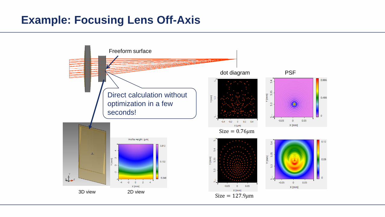
Example Focusing Lens Off-Axis
Freeform surface
3D view 2D view
dot diagram
Size = 076120583120583m
Size = 1279120583120583m
PSF
Direct calculation without optimization in a few seconds
Light Shaping Tasks Geometric Zones Only
Target in geometric field zone bull(GFZ)
bull Shaper in geometric field zone (GFZ)
Shaper Target
Light Shaping Tasks Geometric Zones Only
bull Functional designminus Propagation of field from DFZ into GFZminus Energy conservation leads to identity of
intergal over irradiances in shaper and target planes
minus Together with GFZ assumption phase can be designed
Light Shaping Tasks Geometric Zones Only
Functional designbullPropagation of field from DFZ into GFZminusEnergy conservation leads to identity of minusintergal over irradiances in shaper and target planes Together with GFZ assumption phase minuscan be designed
Light Shaping Tasks Geometric Zones Only
Functional designbullPropagation of field from DFZ into GFZminusEnergy conservation leads to identity of minusintergal over irradiances in shaper and target planes Together with GFZ assumption phase minuscan be designed
Light Shaping Tasks Geometric Zones Only
bull Functional designminus Propagation of field from DFZ into GFZminus Energy conservation leads to identity of
intergal over irradiances in shaper and target planes
minus Together with GFZ assumption phase can be designed
Proc SPIE 1998
Light Shaping Tasks Geometric Zones Only
bull Functional designminus Propagation of field from DFZ into GFZminus Energy conservation leads to identity of
intergal over irradiances in shaper and target planes
minus Together with GFZ assumption phase can be designed
2011
Gaussian to Top-Hat (Non-paraxial)
Gaussian wavehigh NA (001)
input plane
reference plane
target plane
target irradiance
30mm
35mm
35mm2m
m
2mm
20mm
the output NA asymp 04
The Rayleigh lengths of the input Gaussian is 5556microm
Gaussian to Top-Hat (Non-paraxial) Phase Design via Meshes
mesh on reference plane
2mm
2mm
30m
m
30mm
mesh on target plane
Gaussian wavehigh NA (001)
input plane
reference plane
target plane
30mm2mm
2mm
20mm
Gaussian to Top-Hat (Non-paraxial) Functional Embodiment
irradiance at target plane
cross-section (normalized)
Gaussian wavehigh NA (001)
input plane
functional embodiment
target plane
30mm2mm
2mm
20mm
irradiance before the component
irradiance after the component
Gaussian to Top-Hat (Non-paraxial) Functional Embodiment
irradiance at target plane
cross-section (normalized)
Gaussian wavehigh NA (001)
input plane
functional embodiment
target plane
30mm2mm
2mm
20mm
irradiance before the component
irradiance after the component
Resolution of pattern limited by GFZ assumption and NA of system
Light Shaping Tasks Geometric Zones Only
Structural design altrnativesbullFreeform surface design (convergent minusiterative algorithm)HOE design (direct design)minus
bull Functional designminus Propagation of field from DFZ into GFZminus Energy conservation leads to identity of
intergal over irradiances in shaper and target planes
minus Together with GFZ assumption phase can be designed
Gaussian to Top-Hat (Non-paraxial) Freeform Surface
irradiance behind the surface
irradiance at target planeGaussian wavehigh NA (001)
freeform element
target plane
30mm2mm
2mm
20mm
cross-section (normalized)
Height Profile(2D Contour line)
Elliptical Gaussian to Top-Hat (Non-paraxial) Freeform Surface
irradiance behind the surface
irradiance at target planeGaussian wavehigh NA (001)
input plane target
plane
30mm2mm
2mm
20mm
freeform element
cross-section (normalized)
Height Profile(2D Contour line)
Plane Wave to Far Field Pattern (Non-paraxial)
plane wave
input plane
optical element
target plane
target irradiance distribution
100mm
150mm
150mm
14mm
Plane Wave to Far Field Pattern (Non-paraxial) Functional Design
-75
0
-150
75
150mm
-75 0-150 75 150mm
0
-15
15mm
0-15 15mm
mesh on input plane
mesh on target plane
plane wave
input plane
referenceplane
target plane
100mm14mm
Plane Wave to Far Field Pattern (Non-paraxial) Functional
irradiance at target plane(normalized)
error from target irradiance
plane wave
input plane
functional component
target plane
100mm14mm
Resolution of pattern limited by GFZ assumption
Plane Wave to Far Field Pattern (Non-paraxial) Freeform Surface
ray tracing
irradiance at target plane(normalized)
error from target irradianceHeight Profile
(2D Contour line)
Gaussian to Top-Hat (Paraxial) Freeform Surface
Gaussian wavehigh NA (001)
input plane target
plane
300mm
2mm
2mm
20mm
freeformelement
irradiance behind the surface
irradiance at target plane
cross-section (normalized)
Height Profile(2D Contour line)
Field is in slow diffractive field zone
Gaussian to Top-Hat (Paraxial) Freeform Surface
bull Because of paraxial field (slow beams) shaper is in DFZ and not GFZ
bull That results in slight diffractive effects which are not included in design
bull By subsequent iterative Fourier transform algorithm which takes DFZ into account that can be corrected
Gaussian to Top-Hat (Non-paraxial) HOE
Gaussian wavehigh NA (001) HOE
target plane
30mm2mm
2mm
20mm
-1order 0 order +1order
irradiance behind HOE
the output NA asymp 04
Gaussian to Top-Hat (Non-paraxial) HOE
ray tracing result with HOE (with the working order of -1 order)
HOEinputplane
target plane
-1 order
HOEinputplane
target plane
0 order
HOEinputplane
target plane
+1 order
Investigate Rayleigh Coefficient
-1order 0 order +1order
Ex Component behind HOE
cross-section profile result from Grating Toolbox
-1 o
rder
0 or
der
+1 o
rder
the Rayleight coefficient along the cross-section is compared with the result from Grating Toolbox
Modeling with Fourier Modal Method (FMM)
Gaussian to Top-Hat (Non-paraxial) HOE
Gaussian wavehigh NA (001) HOE
target plane
30mm2mm
2mm
20mm
-1order 0 order +1order
irradiance on target plane
Gaussian to Top-Hat (Non-paraxial) Lens + HOE
Gaussian wavehigh NA (001)
HOE target plane
30mm2mm
2mm
20mm
sphericallens
Gaussian to Top-Hat (Non-paraxial) Lens + HOE
Gaussian wavehigh NA (001)
HOE target plane
30mm2mm
2mm
20mm
sphericallens
wavefront behind spherical lens
the Peak-to-Valley wavefront error is 3583120582120582
wavefront error with respect to spherical wavefront
Gaussian to Top-Hat (Non-paraxial) Lens + HOE
The result irradiance on target plane is compared with the previous case without the lens
-1order 0 order +1order
without the lens
with the lens
Light Shaping Tasks Cases
Target in geometric field zone bull(GFZ)
bull Shaper in geometric field zone (GFZ)
Shaper Target
Light Shaping Tasks Gaussian to RingmodeShaper Target
Gaussian to Ringmode Refractive Approach (GFZ)Shaper Target
Gaussian to Ringmode Refractive Approach (GFZ)Shaper Target
Gaussian to Ringmode Diffractive Approach (DFZ)Vortex + Lens Target
DFZ
Gaussian to Ringmode Diffractive Approach (DFZ)Vortex + Lens Target
Diffractive light shaping by coherent superposition
Diffractive beam splitter and diffuser
Shaping by ldquoBeam ScanningrdquoTarget
Basic source mode eg Gaussian
Shaping by ldquoBeam Scanningrdquo
bull Beam splits at shaperbull Field behind shaper is in diffractive field zonebull Shaper is grating DOE
Shaper Target
Target pattern is ldquowrittenrdquo by scanned beam in target plane
Illustration of Deflection
Phase of transmission Intensity in target
Illustration of Deflection
Phase of transmission Intensity in target
Illustration of Deflection
Phase of transmission Intensity in target
Illustration of Deflection
Phase of transmission Intensity in target
Illustration of Deflection
Phase of transmission Intensity in target
Illustration of Deflection Sum
Phase of transmission Intensity in target
Basic Design Situations Splitting
bull Spots overlap in target patten diffractive diffuser
bull Spots in target pattern do not overlap diffractive beam splitter
Basic Design Situations Splitting
bull Spots overlap in target patten diffractive diffuser
Spots in target pattern do not bulloverlap diffractive beam splitter
Shaping by ldquoBeam Scanningrdquo
Amplitude Phase
Iterative Fourier Transform Algorithm
Advanced diffractive optics design techniques
Design technique (IFTA) implemented in VirtualLabtrade
Micro-structured surface profile
Fabricated at IAP University of Jena
Feature Sizes of Element
Feature sizeabout 400 nm
4 height levels
Optical Experiment
Jenaacutes sbquoSkylinelsquo
Comments on Diffuser Technology
Very flexible in light pattern generationbullRobust against adjustment problems bullCoherent light leads to speckle patternbullSize of speckle features can be adjusted by focusing systembullDiffusers work for partially coherent beams bullPartially coherent beams smooth the speckle pattern effect can be simulated bullwith VirtualLabtrade
Diffractive Optics Pattern Generation
Diffuser technology
Diffractive Optics Pattern Generation
Diffuser technology Design very chromatic
Source RGB
Solution by Integrated Diffractive Optics
wwwLightTranscom112
Far Field Propagation
Source Plane Wave RGB Transmission Regions
Waveguide Component
High NA Beam Splitter by Two DOElsquos
Parameter Value amp Unitnumber of orders 11 x 11order separation 1 x 1 degperiod 3035 x 3035 micrompixel size 690 x 690 nmdiscrete height levels 8material fused silica
surfaceprofile
paraxial beam splitter
Specification Second Beam Splitter
Parameter Value amp Unitnumber of orders 5 x 5order separation 11 x 11 degperiod 273 x 273 micrompixel size 130 x 130 nmdiscrete height levels 8material fused silica
surfaceprofile
high-NA beam splitter
Results Spot Diagram
spot diagram
combination of both beam splitter generate 55 x 55 order with 55x 55deg full
opening spread
a
Results Output Evaluation with FMM
Light shaping by lateral decomposition
Elementary cell array components
Array of Deflectors
Array of Deflectors
Deflection can be done by gratings prisms mirrors
TaskSystem Illustration
Cell Array Element
spherical wave(point source)
cell array structurebuilt up withbull prismsbull gratingsbull mirrors
Parameter Description Value amp Unittype RGB LEDemitter size 100 x 100 micromwavelength (473 532 635) nmpolarization right circularly polarized lightnumber of lateral modes 3 x 3Total number of lateral andspectral modes
27
Specification Light Source
Specification Cell Array
Parameter Value amp Unitnumber of cells 100 x 100cell size 125 x 125 micromarray aperture 125 x 125 mm
Results 3D System Ray Tracing
Results Grating Cells Array
spot
dia
gram
inte
nsity
pat
tern
(re
al c
olor
vie
w)
for grating cells array strong dispersion
effects occur
Results Prism Cells Array
spot
dia
gram
inte
nsity
pat
tern
(re
al c
olor
vie
w)
the dispersion is significantly reduced by
using prisms
Results Mirror Cells Array
spot
dia
gram
inte
nsity
pat
tern
(re
al c
olor
vie
w)
due to reflective approach no dispersion
effects occur
Light shaping by lateral decomposition
Lens and freeform array components
Array of Micro-optical Components
Lateral combination of elementary light shaping solutions
TaskSystem Illustration
50 mm Angular Spectrum (Far Field)
LED + collimation optic
aperiodic refractive beam shaper array (aBSA)
camera detector
Specs Light Source
spectrum model
fast and accurate modeling of a white bulllight LEDdesign and analysis an aperiodic bullrefractive beam shaper array to optimize a top hat intensity pattern
Highlightshere
Results Intensity Pattern (real color view)
aperiodic beam shaper array periodic microlens array
a
Summary
Introduction of a geometric branch of physical optics bullwith the help of the geometric Fourier transform Refractive and diffractive light shaping concepts bullfollow a unified theory in physical optics Classification of light shaping concepts dependent of bullpositions of shaper(s) and target in field zones Elementary shaping concepts can be combinedbull
Superposition in same area eg beam splitterminusLaterally combined eg cell arrayminus -type components
Further investigations on the basis of the unified bulltheory will reveal further concepts and deeper understanding of light shaping
bull Designs and simulations done with VirtualLab Fusion software

Light Shaping Tasks Geometric Zones Only
Target in geometric field zone bull(GFZ)
bull Shaper in geometric field zone (GFZ)
Shaper Target
Light Shaping Tasks Geometric Zones Only
bull Functional designminus Propagation of field from DFZ into GFZminus Energy conservation leads to identity of
intergal over irradiances in shaper and target planes
minus Together with GFZ assumption phase can be designed
Light Shaping Tasks Geometric Zones Only
Functional designbullPropagation of field from DFZ into GFZminusEnergy conservation leads to identity of minusintergal over irradiances in shaper and target planes Together with GFZ assumption phase minuscan be designed
Light Shaping Tasks Geometric Zones Only
Functional designbullPropagation of field from DFZ into GFZminusEnergy conservation leads to identity of minusintergal over irradiances in shaper and target planes Together with GFZ assumption phase minuscan be designed
Light Shaping Tasks Geometric Zones Only
bull Functional designminus Propagation of field from DFZ into GFZminus Energy conservation leads to identity of
intergal over irradiances in shaper and target planes
minus Together with GFZ assumption phase can be designed
Proc SPIE 1998
Light Shaping Tasks Geometric Zones Only
bull Functional designminus Propagation of field from DFZ into GFZminus Energy conservation leads to identity of
intergal over irradiances in shaper and target planes
minus Together with GFZ assumption phase can be designed
2011
Gaussian to Top-Hat (Non-paraxial)
Gaussian wavehigh NA (001)
input plane
reference plane
target plane
target irradiance
30mm
35mm
35mm2m
m
2mm
20mm
the output NA asymp 04
The Rayleigh lengths of the input Gaussian is 5556microm
Gaussian to Top-Hat (Non-paraxial) Phase Design via Meshes
mesh on reference plane
2mm
2mm
30m
m
30mm
mesh on target plane
Gaussian wavehigh NA (001)
input plane
reference plane
target plane
30mm2mm
2mm
20mm
Gaussian to Top-Hat (Non-paraxial) Functional Embodiment
irradiance at target plane
cross-section (normalized)
Gaussian wavehigh NA (001)
input plane
functional embodiment
target plane
30mm2mm
2mm
20mm
irradiance before the component
irradiance after the component
Gaussian to Top-Hat (Non-paraxial) Functional Embodiment
irradiance at target plane
cross-section (normalized)
Gaussian wavehigh NA (001)
input plane
functional embodiment
target plane
30mm2mm
2mm
20mm
irradiance before the component
irradiance after the component
Resolution of pattern limited by GFZ assumption and NA of system
Light Shaping Tasks Geometric Zones Only
Structural design altrnativesbullFreeform surface design (convergent minusiterative algorithm)HOE design (direct design)minus
bull Functional designminus Propagation of field from DFZ into GFZminus Energy conservation leads to identity of
intergal over irradiances in shaper and target planes
minus Together with GFZ assumption phase can be designed
Gaussian to Top-Hat (Non-paraxial) Freeform Surface
irradiance behind the surface
irradiance at target planeGaussian wavehigh NA (001)
freeform element
target plane
30mm2mm
2mm
20mm
cross-section (normalized)
Height Profile(2D Contour line)
Elliptical Gaussian to Top-Hat (Non-paraxial) Freeform Surface
irradiance behind the surface
irradiance at target planeGaussian wavehigh NA (001)
input plane target
plane
30mm2mm
2mm
20mm
freeform element
cross-section (normalized)
Height Profile(2D Contour line)
Plane Wave to Far Field Pattern (Non-paraxial)
plane wave
input plane
optical element
target plane
target irradiance distribution
100mm
150mm
150mm
14mm
Plane Wave to Far Field Pattern (Non-paraxial) Functional Design
-75
0
-150
75
150mm
-75 0-150 75 150mm
0
-15
15mm
0-15 15mm
mesh on input plane
mesh on target plane
plane wave
input plane
referenceplane
target plane
100mm14mm
Plane Wave to Far Field Pattern (Non-paraxial) Functional
irradiance at target plane(normalized)
error from target irradiance
plane wave
input plane
functional component
target plane
100mm14mm
Resolution of pattern limited by GFZ assumption
Plane Wave to Far Field Pattern (Non-paraxial) Freeform Surface
ray tracing
irradiance at target plane(normalized)
error from target irradianceHeight Profile
(2D Contour line)
Gaussian to Top-Hat (Paraxial) Freeform Surface
Gaussian wavehigh NA (001)
input plane target
plane
300mm
2mm
2mm
20mm
freeformelement
irradiance behind the surface
irradiance at target plane
cross-section (normalized)
Height Profile(2D Contour line)
Field is in slow diffractive field zone
Gaussian to Top-Hat (Paraxial) Freeform Surface
bull Because of paraxial field (slow beams) shaper is in DFZ and not GFZ
bull That results in slight diffractive effects which are not included in design
bull By subsequent iterative Fourier transform algorithm which takes DFZ into account that can be corrected
Gaussian to Top-Hat (Non-paraxial) HOE
Gaussian wavehigh NA (001) HOE
target plane
30mm2mm
2mm
20mm
-1order 0 order +1order
irradiance behind HOE
the output NA asymp 04
Gaussian to Top-Hat (Non-paraxial) HOE
ray tracing result with HOE (with the working order of -1 order)
HOEinputplane
target plane
-1 order
HOEinputplane
target plane
0 order
HOEinputplane
target plane
+1 order
Investigate Rayleigh Coefficient
-1order 0 order +1order
Ex Component behind HOE
cross-section profile result from Grating Toolbox
-1 o
rder
0 or
der
+1 o
rder
the Rayleight coefficient along the cross-section is compared with the result from Grating Toolbox
Modeling with Fourier Modal Method (FMM)
Gaussian to Top-Hat (Non-paraxial) HOE
Gaussian wavehigh NA (001) HOE
target plane
30mm2mm
2mm
20mm
-1order 0 order +1order
irradiance on target plane
Gaussian to Top-Hat (Non-paraxial) Lens + HOE
Gaussian wavehigh NA (001)
HOE target plane
30mm2mm
2mm
20mm
sphericallens
Gaussian to Top-Hat (Non-paraxial) Lens + HOE
Gaussian wavehigh NA (001)
HOE target plane
30mm2mm
2mm
20mm
sphericallens
wavefront behind spherical lens
the Peak-to-Valley wavefront error is 3583120582120582
wavefront error with respect to spherical wavefront
Gaussian to Top-Hat (Non-paraxial) Lens + HOE
The result irradiance on target plane is compared with the previous case without the lens
-1order 0 order +1order
without the lens
with the lens
Light Shaping Tasks Cases
Target in geometric field zone bull(GFZ)
bull Shaper in geometric field zone (GFZ)
Shaper Target
Light Shaping Tasks Gaussian to RingmodeShaper Target
Gaussian to Ringmode Refractive Approach (GFZ)Shaper Target
Gaussian to Ringmode Refractive Approach (GFZ)Shaper Target
Gaussian to Ringmode Diffractive Approach (DFZ)Vortex + Lens Target
DFZ
Gaussian to Ringmode Diffractive Approach (DFZ)Vortex + Lens Target
Diffractive light shaping by coherent superposition
Diffractive beam splitter and diffuser
Shaping by ldquoBeam ScanningrdquoTarget
Basic source mode eg Gaussian
Shaping by ldquoBeam Scanningrdquo
bull Beam splits at shaperbull Field behind shaper is in diffractive field zonebull Shaper is grating DOE
Shaper Target
Target pattern is ldquowrittenrdquo by scanned beam in target plane
Illustration of Deflection
Phase of transmission Intensity in target
Illustration of Deflection
Phase of transmission Intensity in target
Illustration of Deflection
Phase of transmission Intensity in target
Illustration of Deflection
Phase of transmission Intensity in target
Illustration of Deflection
Phase of transmission Intensity in target
Illustration of Deflection Sum
Phase of transmission Intensity in target
Basic Design Situations Splitting
bull Spots overlap in target patten diffractive diffuser
bull Spots in target pattern do not overlap diffractive beam splitter
Basic Design Situations Splitting
bull Spots overlap in target patten diffractive diffuser
Spots in target pattern do not bulloverlap diffractive beam splitter
Shaping by ldquoBeam Scanningrdquo
Amplitude Phase
Iterative Fourier Transform Algorithm
Advanced diffractive optics design techniques
Design technique (IFTA) implemented in VirtualLabtrade
Micro-structured surface profile
Fabricated at IAP University of Jena
Feature Sizes of Element
Feature sizeabout 400 nm
4 height levels
Optical Experiment
Jenaacutes sbquoSkylinelsquo
Comments on Diffuser Technology
Very flexible in light pattern generationbullRobust against adjustment problems bullCoherent light leads to speckle patternbullSize of speckle features can be adjusted by focusing systembullDiffusers work for partially coherent beams bullPartially coherent beams smooth the speckle pattern effect can be simulated bullwith VirtualLabtrade
Diffractive Optics Pattern Generation
Diffuser technology
Diffractive Optics Pattern Generation
Diffuser technology Design very chromatic
Source RGB
Solution by Integrated Diffractive Optics
wwwLightTranscom112
Far Field Propagation
Source Plane Wave RGB Transmission Regions
Waveguide Component
High NA Beam Splitter by Two DOElsquos
Parameter Value amp Unitnumber of orders 11 x 11order separation 1 x 1 degperiod 3035 x 3035 micrompixel size 690 x 690 nmdiscrete height levels 8material fused silica
surfaceprofile
paraxial beam splitter
Specification Second Beam Splitter
Parameter Value amp Unitnumber of orders 5 x 5order separation 11 x 11 degperiod 273 x 273 micrompixel size 130 x 130 nmdiscrete height levels 8material fused silica
surfaceprofile
high-NA beam splitter
Results Spot Diagram
spot diagram
combination of both beam splitter generate 55 x 55 order with 55x 55deg full
opening spread
a
Results Output Evaluation with FMM
Light shaping by lateral decomposition
Elementary cell array components
Array of Deflectors
Array of Deflectors
Deflection can be done by gratings prisms mirrors
TaskSystem Illustration
Cell Array Element
spherical wave(point source)
cell array structurebuilt up withbull prismsbull gratingsbull mirrors
Parameter Description Value amp Unittype RGB LEDemitter size 100 x 100 micromwavelength (473 532 635) nmpolarization right circularly polarized lightnumber of lateral modes 3 x 3Total number of lateral andspectral modes
27
Specification Light Source
Specification Cell Array
Parameter Value amp Unitnumber of cells 100 x 100cell size 125 x 125 micromarray aperture 125 x 125 mm
Results 3D System Ray Tracing
Results Grating Cells Array
spot
dia
gram
inte
nsity
pat
tern
(re
al c
olor
vie
w)
for grating cells array strong dispersion
effects occur
Results Prism Cells Array
spot
dia
gram
inte
nsity
pat
tern
(re
al c
olor
vie
w)
the dispersion is significantly reduced by
using prisms
Results Mirror Cells Array
spot
dia
gram
inte
nsity
pat
tern
(re
al c
olor
vie
w)
due to reflective approach no dispersion
effects occur
Light shaping by lateral decomposition
Lens and freeform array components
Array of Micro-optical Components
Lateral combination of elementary light shaping solutions
TaskSystem Illustration
50 mm Angular Spectrum (Far Field)
LED + collimation optic
aperiodic refractive beam shaper array (aBSA)
camera detector
Specs Light Source
spectrum model
fast and accurate modeling of a white bulllight LEDdesign and analysis an aperiodic bullrefractive beam shaper array to optimize a top hat intensity pattern
Highlightshere
Results Intensity Pattern (real color view)
aperiodic beam shaper array periodic microlens array
a
Summary
Introduction of a geometric branch of physical optics bullwith the help of the geometric Fourier transform Refractive and diffractive light shaping concepts bullfollow a unified theory in physical optics Classification of light shaping concepts dependent of bullpositions of shaper(s) and target in field zones Elementary shaping concepts can be combinedbull
Superposition in same area eg beam splitterminusLaterally combined eg cell arrayminus -type components
Further investigations on the basis of the unified bulltheory will reveal further concepts and deeper understanding of light shaping
bull Designs and simulations done with VirtualLab Fusion software

Light Shaping Tasks Geometric Zones Only
bull Functional designminus Propagation of field from DFZ into GFZminus Energy conservation leads to identity of
intergal over irradiances in shaper and target planes
minus Together with GFZ assumption phase can be designed
Light Shaping Tasks Geometric Zones Only
Functional designbullPropagation of field from DFZ into GFZminusEnergy conservation leads to identity of minusintergal over irradiances in shaper and target planes Together with GFZ assumption phase minuscan be designed
Light Shaping Tasks Geometric Zones Only
Functional designbullPropagation of field from DFZ into GFZminusEnergy conservation leads to identity of minusintergal over irradiances in shaper and target planes Together with GFZ assumption phase minuscan be designed
Light Shaping Tasks Geometric Zones Only
bull Functional designminus Propagation of field from DFZ into GFZminus Energy conservation leads to identity of
intergal over irradiances in shaper and target planes
minus Together with GFZ assumption phase can be designed
Proc SPIE 1998
Light Shaping Tasks Geometric Zones Only
bull Functional designminus Propagation of field from DFZ into GFZminus Energy conservation leads to identity of
intergal over irradiances in shaper and target planes
minus Together with GFZ assumption phase can be designed
2011
Gaussian to Top-Hat (Non-paraxial)
Gaussian wavehigh NA (001)
input plane
reference plane
target plane
target irradiance
30mm
35mm
35mm2m
m
2mm
20mm
the output NA asymp 04
The Rayleigh lengths of the input Gaussian is 5556microm
Gaussian to Top-Hat (Non-paraxial) Phase Design via Meshes
mesh on reference plane
2mm
2mm
30m
m
30mm
mesh on target plane
Gaussian wavehigh NA (001)
input plane
reference plane
target plane
30mm2mm
2mm
20mm
Gaussian to Top-Hat (Non-paraxial) Functional Embodiment
irradiance at target plane
cross-section (normalized)
Gaussian wavehigh NA (001)
input plane
functional embodiment
target plane
30mm2mm
2mm
20mm
irradiance before the component
irradiance after the component
Gaussian to Top-Hat (Non-paraxial) Functional Embodiment
irradiance at target plane
cross-section (normalized)
Gaussian wavehigh NA (001)
input plane
functional embodiment
target plane
30mm2mm
2mm
20mm
irradiance before the component
irradiance after the component
Resolution of pattern limited by GFZ assumption and NA of system
Light Shaping Tasks Geometric Zones Only
Structural design altrnativesbullFreeform surface design (convergent minusiterative algorithm)HOE design (direct design)minus
bull Functional designminus Propagation of field from DFZ into GFZminus Energy conservation leads to identity of
intergal over irradiances in shaper and target planes
minus Together with GFZ assumption phase can be designed
Gaussian to Top-Hat (Non-paraxial) Freeform Surface
irradiance behind the surface
irradiance at target planeGaussian wavehigh NA (001)
freeform element
target plane
30mm2mm
2mm
20mm
cross-section (normalized)
Height Profile(2D Contour line)
Elliptical Gaussian to Top-Hat (Non-paraxial) Freeform Surface
irradiance behind the surface
irradiance at target planeGaussian wavehigh NA (001)
input plane target
plane
30mm2mm
2mm
20mm
freeform element
cross-section (normalized)
Height Profile(2D Contour line)
Plane Wave to Far Field Pattern (Non-paraxial)
plane wave
input plane
optical element
target plane
target irradiance distribution
100mm
150mm
150mm
14mm
Plane Wave to Far Field Pattern (Non-paraxial) Functional Design
-75
0
-150
75
150mm
-75 0-150 75 150mm
0
-15
15mm
0-15 15mm
mesh on input plane
mesh on target plane
plane wave
input plane
referenceplane
target plane
100mm14mm
Plane Wave to Far Field Pattern (Non-paraxial) Functional
irradiance at target plane(normalized)
error from target irradiance
plane wave
input plane
functional component
target plane
100mm14mm
Resolution of pattern limited by GFZ assumption
Plane Wave to Far Field Pattern (Non-paraxial) Freeform Surface
ray tracing
irradiance at target plane(normalized)
error from target irradianceHeight Profile
(2D Contour line)
Gaussian to Top-Hat (Paraxial) Freeform Surface
Gaussian wavehigh NA (001)
input plane target
plane
300mm
2mm
2mm
20mm
freeformelement
irradiance behind the surface
irradiance at target plane
cross-section (normalized)
Height Profile(2D Contour line)
Field is in slow diffractive field zone
Gaussian to Top-Hat (Paraxial) Freeform Surface
bull Because of paraxial field (slow beams) shaper is in DFZ and not GFZ
bull That results in slight diffractive effects which are not included in design
bull By subsequent iterative Fourier transform algorithm which takes DFZ into account that can be corrected
Gaussian to Top-Hat (Non-paraxial) HOE
Gaussian wavehigh NA (001) HOE
target plane
30mm2mm
2mm
20mm
-1order 0 order +1order
irradiance behind HOE
the output NA asymp 04
Gaussian to Top-Hat (Non-paraxial) HOE
ray tracing result with HOE (with the working order of -1 order)
HOEinputplane
target plane
-1 order
HOEinputplane
target plane
0 order
HOEinputplane
target plane
+1 order
Investigate Rayleigh Coefficient
-1order 0 order +1order
Ex Component behind HOE
cross-section profile result from Grating Toolbox
-1 o
rder
0 or
der
+1 o
rder
the Rayleight coefficient along the cross-section is compared with the result from Grating Toolbox
Modeling with Fourier Modal Method (FMM)
Gaussian to Top-Hat (Non-paraxial) HOE
Gaussian wavehigh NA (001) HOE
target plane
30mm2mm
2mm
20mm
-1order 0 order +1order
irradiance on target plane
Gaussian to Top-Hat (Non-paraxial) Lens + HOE
Gaussian wavehigh NA (001)
HOE target plane
30mm2mm
2mm
20mm
sphericallens
Gaussian to Top-Hat (Non-paraxial) Lens + HOE
Gaussian wavehigh NA (001)
HOE target plane
30mm2mm
2mm
20mm
sphericallens
wavefront behind spherical lens
the Peak-to-Valley wavefront error is 3583120582120582
wavefront error with respect to spherical wavefront
Gaussian to Top-Hat (Non-paraxial) Lens + HOE
The result irradiance on target plane is compared with the previous case without the lens
-1order 0 order +1order
without the lens
with the lens
Light Shaping Tasks Cases
Target in geometric field zone bull(GFZ)
bull Shaper in geometric field zone (GFZ)
Shaper Target
Light Shaping Tasks Gaussian to RingmodeShaper Target
Gaussian to Ringmode Refractive Approach (GFZ)Shaper Target
Gaussian to Ringmode Refractive Approach (GFZ)Shaper Target
Gaussian to Ringmode Diffractive Approach (DFZ)Vortex + Lens Target
DFZ
Gaussian to Ringmode Diffractive Approach (DFZ)Vortex + Lens Target
Diffractive light shaping by coherent superposition
Diffractive beam splitter and diffuser
Shaping by ldquoBeam ScanningrdquoTarget
Basic source mode eg Gaussian
Shaping by ldquoBeam Scanningrdquo
bull Beam splits at shaperbull Field behind shaper is in diffractive field zonebull Shaper is grating DOE
Shaper Target
Target pattern is ldquowrittenrdquo by scanned beam in target plane
Illustration of Deflection
Phase of transmission Intensity in target
Illustration of Deflection
Phase of transmission Intensity in target
Illustration of Deflection
Phase of transmission Intensity in target
Illustration of Deflection
Phase of transmission Intensity in target
Illustration of Deflection
Phase of transmission Intensity in target
Illustration of Deflection Sum
Phase of transmission Intensity in target
Basic Design Situations Splitting
bull Spots overlap in target patten diffractive diffuser
bull Spots in target pattern do not overlap diffractive beam splitter
Basic Design Situations Splitting
bull Spots overlap in target patten diffractive diffuser
Spots in target pattern do not bulloverlap diffractive beam splitter
Shaping by ldquoBeam Scanningrdquo
Amplitude Phase
Iterative Fourier Transform Algorithm
Advanced diffractive optics design techniques
Design technique (IFTA) implemented in VirtualLabtrade
Micro-structured surface profile
Fabricated at IAP University of Jena
Feature Sizes of Element
Feature sizeabout 400 nm
4 height levels
Optical Experiment
Jenaacutes sbquoSkylinelsquo
Comments on Diffuser Technology
Very flexible in light pattern generationbullRobust against adjustment problems bullCoherent light leads to speckle patternbullSize of speckle features can be adjusted by focusing systembullDiffusers work for partially coherent beams bullPartially coherent beams smooth the speckle pattern effect can be simulated bullwith VirtualLabtrade
Diffractive Optics Pattern Generation
Diffuser technology
Diffractive Optics Pattern Generation
Diffuser technology Design very chromatic
Source RGB
Solution by Integrated Diffractive Optics
wwwLightTranscom112
Far Field Propagation
Source Plane Wave RGB Transmission Regions
Waveguide Component
High NA Beam Splitter by Two DOElsquos
Parameter Value amp Unitnumber of orders 11 x 11order separation 1 x 1 degperiod 3035 x 3035 micrompixel size 690 x 690 nmdiscrete height levels 8material fused silica
surfaceprofile
paraxial beam splitter
Specification Second Beam Splitter
Parameter Value amp Unitnumber of orders 5 x 5order separation 11 x 11 degperiod 273 x 273 micrompixel size 130 x 130 nmdiscrete height levels 8material fused silica
surfaceprofile
high-NA beam splitter
Results Spot Diagram
spot diagram
combination of both beam splitter generate 55 x 55 order with 55x 55deg full
opening spread
a
Results Output Evaluation with FMM
Light shaping by lateral decomposition
Elementary cell array components
Array of Deflectors
Array of Deflectors
Deflection can be done by gratings prisms mirrors
TaskSystem Illustration
Cell Array Element
spherical wave(point source)
cell array structurebuilt up withbull prismsbull gratingsbull mirrors
Parameter Description Value amp Unittype RGB LEDemitter size 100 x 100 micromwavelength (473 532 635) nmpolarization right circularly polarized lightnumber of lateral modes 3 x 3Total number of lateral andspectral modes
27
Specification Light Source
Specification Cell Array
Parameter Value amp Unitnumber of cells 100 x 100cell size 125 x 125 micromarray aperture 125 x 125 mm
Results 3D System Ray Tracing
Results Grating Cells Array
spot
dia
gram
inte
nsity
pat
tern
(re
al c
olor
vie
w)
for grating cells array strong dispersion
effects occur
Results Prism Cells Array
spot
dia
gram
inte
nsity
pat
tern
(re
al c
olor
vie
w)
the dispersion is significantly reduced by
using prisms
Results Mirror Cells Array
spot
dia
gram
inte
nsity
pat
tern
(re
al c
olor
vie
w)
due to reflective approach no dispersion
effects occur
Light shaping by lateral decomposition
Lens and freeform array components
Array of Micro-optical Components
Lateral combination of elementary light shaping solutions
TaskSystem Illustration
50 mm Angular Spectrum (Far Field)
LED + collimation optic
aperiodic refractive beam shaper array (aBSA)
camera detector
Specs Light Source
spectrum model
fast and accurate modeling of a white bulllight LEDdesign and analysis an aperiodic bullrefractive beam shaper array to optimize a top hat intensity pattern
Highlightshere
Results Intensity Pattern (real color view)
aperiodic beam shaper array periodic microlens array
a
Summary
Introduction of a geometric branch of physical optics bullwith the help of the geometric Fourier transform Refractive and diffractive light shaping concepts bullfollow a unified theory in physical optics Classification of light shaping concepts dependent of bullpositions of shaper(s) and target in field zones Elementary shaping concepts can be combinedbull
Superposition in same area eg beam splitterminusLaterally combined eg cell arrayminus -type components
Further investigations on the basis of the unified bulltheory will reveal further concepts and deeper understanding of light shaping
bull Designs and simulations done with VirtualLab Fusion software
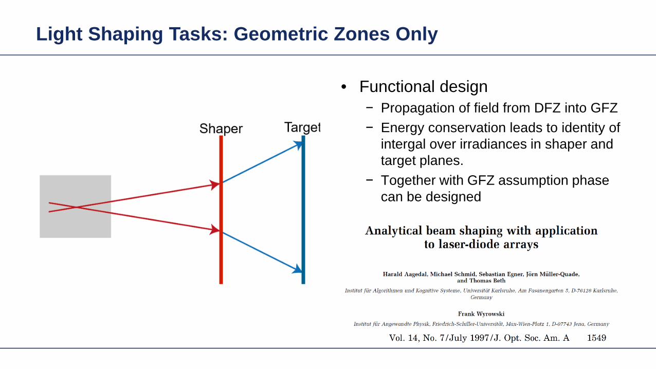
Light Shaping Tasks Geometric Zones Only
Functional designbullPropagation of field from DFZ into GFZminusEnergy conservation leads to identity of minusintergal over irradiances in shaper and target planes Together with GFZ assumption phase minuscan be designed
Light Shaping Tasks Geometric Zones Only
Functional designbullPropagation of field from DFZ into GFZminusEnergy conservation leads to identity of minusintergal over irradiances in shaper and target planes Together with GFZ assumption phase minuscan be designed
Light Shaping Tasks Geometric Zones Only
bull Functional designminus Propagation of field from DFZ into GFZminus Energy conservation leads to identity of
intergal over irradiances in shaper and target planes
minus Together with GFZ assumption phase can be designed
Proc SPIE 1998
Light Shaping Tasks Geometric Zones Only
bull Functional designminus Propagation of field from DFZ into GFZminus Energy conservation leads to identity of
intergal over irradiances in shaper and target planes
minus Together with GFZ assumption phase can be designed
2011
Gaussian to Top-Hat (Non-paraxial)
Gaussian wavehigh NA (001)
input plane
reference plane
target plane
target irradiance
30mm
35mm
35mm2m
m
2mm
20mm
the output NA asymp 04
The Rayleigh lengths of the input Gaussian is 5556microm
Gaussian to Top-Hat (Non-paraxial) Phase Design via Meshes
mesh on reference plane
2mm
2mm
30m
m
30mm
mesh on target plane
Gaussian wavehigh NA (001)
input plane
reference plane
target plane
30mm2mm
2mm
20mm
Gaussian to Top-Hat (Non-paraxial) Functional Embodiment
irradiance at target plane
cross-section (normalized)
Gaussian wavehigh NA (001)
input plane
functional embodiment
target plane
30mm2mm
2mm
20mm
irradiance before the component
irradiance after the component
Gaussian to Top-Hat (Non-paraxial) Functional Embodiment
irradiance at target plane
cross-section (normalized)
Gaussian wavehigh NA (001)
input plane
functional embodiment
target plane
30mm2mm
2mm
20mm
irradiance before the component
irradiance after the component
Resolution of pattern limited by GFZ assumption and NA of system
Light Shaping Tasks Geometric Zones Only
Structural design altrnativesbullFreeform surface design (convergent minusiterative algorithm)HOE design (direct design)minus
bull Functional designminus Propagation of field from DFZ into GFZminus Energy conservation leads to identity of
intergal over irradiances in shaper and target planes
minus Together with GFZ assumption phase can be designed
Gaussian to Top-Hat (Non-paraxial) Freeform Surface
irradiance behind the surface
irradiance at target planeGaussian wavehigh NA (001)
freeform element
target plane
30mm2mm
2mm
20mm
cross-section (normalized)
Height Profile(2D Contour line)
Elliptical Gaussian to Top-Hat (Non-paraxial) Freeform Surface
irradiance behind the surface
irradiance at target planeGaussian wavehigh NA (001)
input plane target
plane
30mm2mm
2mm
20mm
freeform element
cross-section (normalized)
Height Profile(2D Contour line)
Plane Wave to Far Field Pattern (Non-paraxial)
plane wave
input plane
optical element
target plane
target irradiance distribution
100mm
150mm
150mm
14mm
Plane Wave to Far Field Pattern (Non-paraxial) Functional Design
-75
0
-150
75
150mm
-75 0-150 75 150mm
0
-15
15mm
0-15 15mm
mesh on input plane
mesh on target plane
plane wave
input plane
referenceplane
target plane
100mm14mm
Plane Wave to Far Field Pattern (Non-paraxial) Functional
irradiance at target plane(normalized)
error from target irradiance
plane wave
input plane
functional component
target plane
100mm14mm
Resolution of pattern limited by GFZ assumption
Plane Wave to Far Field Pattern (Non-paraxial) Freeform Surface
ray tracing
irradiance at target plane(normalized)
error from target irradianceHeight Profile
(2D Contour line)
Gaussian to Top-Hat (Paraxial) Freeform Surface
Gaussian wavehigh NA (001)
input plane target
plane
300mm
2mm
2mm
20mm
freeformelement
irradiance behind the surface
irradiance at target plane
cross-section (normalized)
Height Profile(2D Contour line)
Field is in slow diffractive field zone
Gaussian to Top-Hat (Paraxial) Freeform Surface
bull Because of paraxial field (slow beams) shaper is in DFZ and not GFZ
bull That results in slight diffractive effects which are not included in design
bull By subsequent iterative Fourier transform algorithm which takes DFZ into account that can be corrected
Gaussian to Top-Hat (Non-paraxial) HOE
Gaussian wavehigh NA (001) HOE
target plane
30mm2mm
2mm
20mm
-1order 0 order +1order
irradiance behind HOE
the output NA asymp 04
Gaussian to Top-Hat (Non-paraxial) HOE
ray tracing result with HOE (with the working order of -1 order)
HOEinputplane
target plane
-1 order
HOEinputplane
target plane
0 order
HOEinputplane
target plane
+1 order
Investigate Rayleigh Coefficient
-1order 0 order +1order
Ex Component behind HOE
cross-section profile result from Grating Toolbox
-1 o
rder
0 or
der
+1 o
rder
the Rayleight coefficient along the cross-section is compared with the result from Grating Toolbox
Modeling with Fourier Modal Method (FMM)
Gaussian to Top-Hat (Non-paraxial) HOE
Gaussian wavehigh NA (001) HOE
target plane
30mm2mm
2mm
20mm
-1order 0 order +1order
irradiance on target plane
Gaussian to Top-Hat (Non-paraxial) Lens + HOE
Gaussian wavehigh NA (001)
HOE target plane
30mm2mm
2mm
20mm
sphericallens
Gaussian to Top-Hat (Non-paraxial) Lens + HOE
Gaussian wavehigh NA (001)
HOE target plane
30mm2mm
2mm
20mm
sphericallens
wavefront behind spherical lens
the Peak-to-Valley wavefront error is 3583120582120582
wavefront error with respect to spherical wavefront
Gaussian to Top-Hat (Non-paraxial) Lens + HOE
The result irradiance on target plane is compared with the previous case without the lens
-1order 0 order +1order
without the lens
with the lens
Light Shaping Tasks Cases
Target in geometric field zone bull(GFZ)
bull Shaper in geometric field zone (GFZ)
Shaper Target
Light Shaping Tasks Gaussian to RingmodeShaper Target
Gaussian to Ringmode Refractive Approach (GFZ)Shaper Target
Gaussian to Ringmode Refractive Approach (GFZ)Shaper Target
Gaussian to Ringmode Diffractive Approach (DFZ)Vortex + Lens Target
DFZ
Gaussian to Ringmode Diffractive Approach (DFZ)Vortex + Lens Target
Diffractive light shaping by coherent superposition
Diffractive beam splitter and diffuser
Shaping by ldquoBeam ScanningrdquoTarget
Basic source mode eg Gaussian
Shaping by ldquoBeam Scanningrdquo
bull Beam splits at shaperbull Field behind shaper is in diffractive field zonebull Shaper is grating DOE
Shaper Target
Target pattern is ldquowrittenrdquo by scanned beam in target plane
Illustration of Deflection
Phase of transmission Intensity in target
Illustration of Deflection
Phase of transmission Intensity in target
Illustration of Deflection
Phase of transmission Intensity in target
Illustration of Deflection
Phase of transmission Intensity in target
Illustration of Deflection
Phase of transmission Intensity in target
Illustration of Deflection Sum
Phase of transmission Intensity in target
Basic Design Situations Splitting
bull Spots overlap in target patten diffractive diffuser
bull Spots in target pattern do not overlap diffractive beam splitter
Basic Design Situations Splitting
bull Spots overlap in target patten diffractive diffuser
Spots in target pattern do not bulloverlap diffractive beam splitter
Shaping by ldquoBeam Scanningrdquo
Amplitude Phase
Iterative Fourier Transform Algorithm
Advanced diffractive optics design techniques
Design technique (IFTA) implemented in VirtualLabtrade
Micro-structured surface profile
Fabricated at IAP University of Jena
Feature Sizes of Element
Feature sizeabout 400 nm
4 height levels
Optical Experiment
Jenaacutes sbquoSkylinelsquo
Comments on Diffuser Technology
Very flexible in light pattern generationbullRobust against adjustment problems bullCoherent light leads to speckle patternbullSize of speckle features can be adjusted by focusing systembullDiffusers work for partially coherent beams bullPartially coherent beams smooth the speckle pattern effect can be simulated bullwith VirtualLabtrade
Diffractive Optics Pattern Generation
Diffuser technology
Diffractive Optics Pattern Generation
Diffuser technology Design very chromatic
Source RGB
Solution by Integrated Diffractive Optics
wwwLightTranscom112
Far Field Propagation
Source Plane Wave RGB Transmission Regions
Waveguide Component
High NA Beam Splitter by Two DOElsquos
Parameter Value amp Unitnumber of orders 11 x 11order separation 1 x 1 degperiod 3035 x 3035 micrompixel size 690 x 690 nmdiscrete height levels 8material fused silica
surfaceprofile
paraxial beam splitter
Specification Second Beam Splitter
Parameter Value amp Unitnumber of orders 5 x 5order separation 11 x 11 degperiod 273 x 273 micrompixel size 130 x 130 nmdiscrete height levels 8material fused silica
surfaceprofile
high-NA beam splitter
Results Spot Diagram
spot diagram
combination of both beam splitter generate 55 x 55 order with 55x 55deg full
opening spread
a
Results Output Evaluation with FMM
Light shaping by lateral decomposition
Elementary cell array components
Array of Deflectors
Array of Deflectors
Deflection can be done by gratings prisms mirrors
TaskSystem Illustration
Cell Array Element
spherical wave(point source)
cell array structurebuilt up withbull prismsbull gratingsbull mirrors
Parameter Description Value amp Unittype RGB LEDemitter size 100 x 100 micromwavelength (473 532 635) nmpolarization right circularly polarized lightnumber of lateral modes 3 x 3Total number of lateral andspectral modes
27
Specification Light Source
Specification Cell Array
Parameter Value amp Unitnumber of cells 100 x 100cell size 125 x 125 micromarray aperture 125 x 125 mm
Results 3D System Ray Tracing
Results Grating Cells Array
spot
dia
gram
inte
nsity
pat
tern
(re
al c
olor
vie
w)
for grating cells array strong dispersion
effects occur
Results Prism Cells Array
spot
dia
gram
inte
nsity
pat
tern
(re
al c
olor
vie
w)
the dispersion is significantly reduced by
using prisms
Results Mirror Cells Array
spot
dia
gram
inte
nsity
pat
tern
(re
al c
olor
vie
w)
due to reflective approach no dispersion
effects occur
Light shaping by lateral decomposition
Lens and freeform array components
Array of Micro-optical Components
Lateral combination of elementary light shaping solutions
TaskSystem Illustration
50 mm Angular Spectrum (Far Field)
LED + collimation optic
aperiodic refractive beam shaper array (aBSA)
camera detector
Specs Light Source
spectrum model
fast and accurate modeling of a white bulllight LEDdesign and analysis an aperiodic bullrefractive beam shaper array to optimize a top hat intensity pattern
Highlightshere
Results Intensity Pattern (real color view)
aperiodic beam shaper array periodic microlens array
a
Summary
Introduction of a geometric branch of physical optics bullwith the help of the geometric Fourier transform Refractive and diffractive light shaping concepts bullfollow a unified theory in physical optics Classification of light shaping concepts dependent of bullpositions of shaper(s) and target in field zones Elementary shaping concepts can be combinedbull
Superposition in same area eg beam splitterminusLaterally combined eg cell arrayminus -type components
Further investigations on the basis of the unified bulltheory will reveal further concepts and deeper understanding of light shaping
bull Designs and simulations done with VirtualLab Fusion software
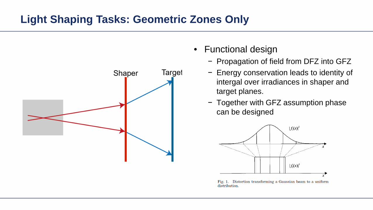
Light Shaping Tasks Geometric Zones Only
Functional designbullPropagation of field from DFZ into GFZminusEnergy conservation leads to identity of minusintergal over irradiances in shaper and target planes Together with GFZ assumption phase minuscan be designed
Light Shaping Tasks Geometric Zones Only
bull Functional designminus Propagation of field from DFZ into GFZminus Energy conservation leads to identity of
intergal over irradiances in shaper and target planes
minus Together with GFZ assumption phase can be designed
Proc SPIE 1998
Light Shaping Tasks Geometric Zones Only
bull Functional designminus Propagation of field from DFZ into GFZminus Energy conservation leads to identity of
intergal over irradiances in shaper and target planes
minus Together with GFZ assumption phase can be designed
2011
Gaussian to Top-Hat (Non-paraxial)
Gaussian wavehigh NA (001)
input plane
reference plane
target plane
target irradiance
30mm
35mm
35mm2m
m
2mm
20mm
the output NA asymp 04
The Rayleigh lengths of the input Gaussian is 5556microm
Gaussian to Top-Hat (Non-paraxial) Phase Design via Meshes
mesh on reference plane
2mm
2mm
30m
m
30mm
mesh on target plane
Gaussian wavehigh NA (001)
input plane
reference plane
target plane
30mm2mm
2mm
20mm
Gaussian to Top-Hat (Non-paraxial) Functional Embodiment
irradiance at target plane
cross-section (normalized)
Gaussian wavehigh NA (001)
input plane
functional embodiment
target plane
30mm2mm
2mm
20mm
irradiance before the component
irradiance after the component
Gaussian to Top-Hat (Non-paraxial) Functional Embodiment
irradiance at target plane
cross-section (normalized)
Gaussian wavehigh NA (001)
input plane
functional embodiment
target plane
30mm2mm
2mm
20mm
irradiance before the component
irradiance after the component
Resolution of pattern limited by GFZ assumption and NA of system
Light Shaping Tasks Geometric Zones Only
Structural design altrnativesbullFreeform surface design (convergent minusiterative algorithm)HOE design (direct design)minus
bull Functional designminus Propagation of field from DFZ into GFZminus Energy conservation leads to identity of
intergal over irradiances in shaper and target planes
minus Together with GFZ assumption phase can be designed
Gaussian to Top-Hat (Non-paraxial) Freeform Surface
irradiance behind the surface
irradiance at target planeGaussian wavehigh NA (001)
freeform element
target plane
30mm2mm
2mm
20mm
cross-section (normalized)
Height Profile(2D Contour line)
Elliptical Gaussian to Top-Hat (Non-paraxial) Freeform Surface
irradiance behind the surface
irradiance at target planeGaussian wavehigh NA (001)
input plane target
plane
30mm2mm
2mm
20mm
freeform element
cross-section (normalized)
Height Profile(2D Contour line)
Plane Wave to Far Field Pattern (Non-paraxial)
plane wave
input plane
optical element
target plane
target irradiance distribution
100mm
150mm
150mm
14mm
Plane Wave to Far Field Pattern (Non-paraxial) Functional Design
-75
0
-150
75
150mm
-75 0-150 75 150mm
0
-15
15mm
0-15 15mm
mesh on input plane
mesh on target plane
plane wave
input plane
referenceplane
target plane
100mm14mm
Plane Wave to Far Field Pattern (Non-paraxial) Functional
irradiance at target plane(normalized)
error from target irradiance
plane wave
input plane
functional component
target plane
100mm14mm
Resolution of pattern limited by GFZ assumption
Plane Wave to Far Field Pattern (Non-paraxial) Freeform Surface
ray tracing
irradiance at target plane(normalized)
error from target irradianceHeight Profile
(2D Contour line)
Gaussian to Top-Hat (Paraxial) Freeform Surface
Gaussian wavehigh NA (001)
input plane target
plane
300mm
2mm
2mm
20mm
freeformelement
irradiance behind the surface
irradiance at target plane
cross-section (normalized)
Height Profile(2D Contour line)
Field is in slow diffractive field zone
Gaussian to Top-Hat (Paraxial) Freeform Surface
bull Because of paraxial field (slow beams) shaper is in DFZ and not GFZ
bull That results in slight diffractive effects which are not included in design
bull By subsequent iterative Fourier transform algorithm which takes DFZ into account that can be corrected
Gaussian to Top-Hat (Non-paraxial) HOE
Gaussian wavehigh NA (001) HOE
target plane
30mm2mm
2mm
20mm
-1order 0 order +1order
irradiance behind HOE
the output NA asymp 04
Gaussian to Top-Hat (Non-paraxial) HOE
ray tracing result with HOE (with the working order of -1 order)
HOEinputplane
target plane
-1 order
HOEinputplane
target plane
0 order
HOEinputplane
target plane
+1 order
Investigate Rayleigh Coefficient
-1order 0 order +1order
Ex Component behind HOE
cross-section profile result from Grating Toolbox
-1 o
rder
0 or
der
+1 o
rder
the Rayleight coefficient along the cross-section is compared with the result from Grating Toolbox
Modeling with Fourier Modal Method (FMM)
Gaussian to Top-Hat (Non-paraxial) HOE
Gaussian wavehigh NA (001) HOE
target plane
30mm2mm
2mm
20mm
-1order 0 order +1order
irradiance on target plane
Gaussian to Top-Hat (Non-paraxial) Lens + HOE
Gaussian wavehigh NA (001)
HOE target plane
30mm2mm
2mm
20mm
sphericallens
Gaussian to Top-Hat (Non-paraxial) Lens + HOE
Gaussian wavehigh NA (001)
HOE target plane
30mm2mm
2mm
20mm
sphericallens
wavefront behind spherical lens
the Peak-to-Valley wavefront error is 3583120582120582
wavefront error with respect to spherical wavefront
Gaussian to Top-Hat (Non-paraxial) Lens + HOE
The result irradiance on target plane is compared with the previous case without the lens
-1order 0 order +1order
without the lens
with the lens
Light Shaping Tasks Cases
Target in geometric field zone bull(GFZ)
bull Shaper in geometric field zone (GFZ)
Shaper Target
Light Shaping Tasks Gaussian to RingmodeShaper Target
Gaussian to Ringmode Refractive Approach (GFZ)Shaper Target
Gaussian to Ringmode Refractive Approach (GFZ)Shaper Target
Gaussian to Ringmode Diffractive Approach (DFZ)Vortex + Lens Target
DFZ
Gaussian to Ringmode Diffractive Approach (DFZ)Vortex + Lens Target
Diffractive light shaping by coherent superposition
Diffractive beam splitter and diffuser
Shaping by ldquoBeam ScanningrdquoTarget
Basic source mode eg Gaussian
Shaping by ldquoBeam Scanningrdquo
bull Beam splits at shaperbull Field behind shaper is in diffractive field zonebull Shaper is grating DOE
Shaper Target
Target pattern is ldquowrittenrdquo by scanned beam in target plane
Illustration of Deflection
Phase of transmission Intensity in target
Illustration of Deflection
Phase of transmission Intensity in target
Illustration of Deflection
Phase of transmission Intensity in target
Illustration of Deflection
Phase of transmission Intensity in target
Illustration of Deflection
Phase of transmission Intensity in target
Illustration of Deflection Sum
Phase of transmission Intensity in target
Basic Design Situations Splitting
bull Spots overlap in target patten diffractive diffuser
bull Spots in target pattern do not overlap diffractive beam splitter
Basic Design Situations Splitting
bull Spots overlap in target patten diffractive diffuser
Spots in target pattern do not bulloverlap diffractive beam splitter
Shaping by ldquoBeam Scanningrdquo
Amplitude Phase
Iterative Fourier Transform Algorithm
Advanced diffractive optics design techniques
Design technique (IFTA) implemented in VirtualLabtrade
Micro-structured surface profile
Fabricated at IAP University of Jena
Feature Sizes of Element
Feature sizeabout 400 nm
4 height levels
Optical Experiment
Jenaacutes sbquoSkylinelsquo
Comments on Diffuser Technology
Very flexible in light pattern generationbullRobust against adjustment problems bullCoherent light leads to speckle patternbullSize of speckle features can be adjusted by focusing systembullDiffusers work for partially coherent beams bullPartially coherent beams smooth the speckle pattern effect can be simulated bullwith VirtualLabtrade
Diffractive Optics Pattern Generation
Diffuser technology
Diffractive Optics Pattern Generation
Diffuser technology Design very chromatic
Source RGB
Solution by Integrated Diffractive Optics
wwwLightTranscom112
Far Field Propagation
Source Plane Wave RGB Transmission Regions
Waveguide Component
High NA Beam Splitter by Two DOElsquos
Parameter Value amp Unitnumber of orders 11 x 11order separation 1 x 1 degperiod 3035 x 3035 micrompixel size 690 x 690 nmdiscrete height levels 8material fused silica
surfaceprofile
paraxial beam splitter
Specification Second Beam Splitter
Parameter Value amp Unitnumber of orders 5 x 5order separation 11 x 11 degperiod 273 x 273 micrompixel size 130 x 130 nmdiscrete height levels 8material fused silica
surfaceprofile
high-NA beam splitter
Results Spot Diagram
spot diagram
combination of both beam splitter generate 55 x 55 order with 55x 55deg full
opening spread
a
Results Output Evaluation with FMM
Light shaping by lateral decomposition
Elementary cell array components
Array of Deflectors
Array of Deflectors
Deflection can be done by gratings prisms mirrors
TaskSystem Illustration
Cell Array Element
spherical wave(point source)
cell array structurebuilt up withbull prismsbull gratingsbull mirrors
Parameter Description Value amp Unittype RGB LEDemitter size 100 x 100 micromwavelength (473 532 635) nmpolarization right circularly polarized lightnumber of lateral modes 3 x 3Total number of lateral andspectral modes
27
Specification Light Source
Specification Cell Array
Parameter Value amp Unitnumber of cells 100 x 100cell size 125 x 125 micromarray aperture 125 x 125 mm
Results 3D System Ray Tracing
Results Grating Cells Array
spot
dia
gram
inte
nsity
pat
tern
(re
al c
olor
vie
w)
for grating cells array strong dispersion
effects occur
Results Prism Cells Array
spot
dia
gram
inte
nsity
pat
tern
(re
al c
olor
vie
w)
the dispersion is significantly reduced by
using prisms
Results Mirror Cells Array
spot
dia
gram
inte
nsity
pat
tern
(re
al c
olor
vie
w)
due to reflective approach no dispersion
effects occur
Light shaping by lateral decomposition
Lens and freeform array components
Array of Micro-optical Components
Lateral combination of elementary light shaping solutions
TaskSystem Illustration
50 mm Angular Spectrum (Far Field)
LED + collimation optic
aperiodic refractive beam shaper array (aBSA)
camera detector
Specs Light Source
spectrum model
fast and accurate modeling of a white bulllight LEDdesign and analysis an aperiodic bullrefractive beam shaper array to optimize a top hat intensity pattern
Highlightshere
Results Intensity Pattern (real color view)
aperiodic beam shaper array periodic microlens array
a
Summary
Introduction of a geometric branch of physical optics bullwith the help of the geometric Fourier transform Refractive and diffractive light shaping concepts bullfollow a unified theory in physical optics Classification of light shaping concepts dependent of bullpositions of shaper(s) and target in field zones Elementary shaping concepts can be combinedbull
Superposition in same area eg beam splitterminusLaterally combined eg cell arrayminus -type components
Further investigations on the basis of the unified bulltheory will reveal further concepts and deeper understanding of light shaping
bull Designs and simulations done with VirtualLab Fusion software
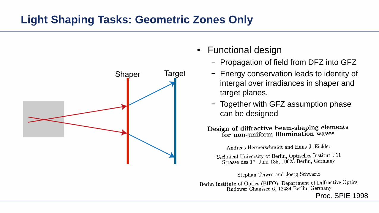
Light Shaping Tasks Geometric Zones Only
bull Functional designminus Propagation of field from DFZ into GFZminus Energy conservation leads to identity of
intergal over irradiances in shaper and target planes
minus Together with GFZ assumption phase can be designed
Proc SPIE 1998
Light Shaping Tasks Geometric Zones Only
bull Functional designminus Propagation of field from DFZ into GFZminus Energy conservation leads to identity of
intergal over irradiances in shaper and target planes
minus Together with GFZ assumption phase can be designed
2011
Gaussian to Top-Hat (Non-paraxial)
Gaussian wavehigh NA (001)
input plane
reference plane
target plane
target irradiance
30mm
35mm
35mm2m
m
2mm
20mm
the output NA asymp 04
The Rayleigh lengths of the input Gaussian is 5556microm
Gaussian to Top-Hat (Non-paraxial) Phase Design via Meshes
mesh on reference plane
2mm
2mm
30m
m
30mm
mesh on target plane
Gaussian wavehigh NA (001)
input plane
reference plane
target plane
30mm2mm
2mm
20mm
Gaussian to Top-Hat (Non-paraxial) Functional Embodiment
irradiance at target plane
cross-section (normalized)
Gaussian wavehigh NA (001)
input plane
functional embodiment
target plane
30mm2mm
2mm
20mm
irradiance before the component
irradiance after the component
Gaussian to Top-Hat (Non-paraxial) Functional Embodiment
irradiance at target plane
cross-section (normalized)
Gaussian wavehigh NA (001)
input plane
functional embodiment
target plane
30mm2mm
2mm
20mm
irradiance before the component
irradiance after the component
Resolution of pattern limited by GFZ assumption and NA of system
Light Shaping Tasks Geometric Zones Only
Structural design altrnativesbullFreeform surface design (convergent minusiterative algorithm)HOE design (direct design)minus
bull Functional designminus Propagation of field from DFZ into GFZminus Energy conservation leads to identity of
intergal over irradiances in shaper and target planes
minus Together with GFZ assumption phase can be designed
Gaussian to Top-Hat (Non-paraxial) Freeform Surface
irradiance behind the surface
irradiance at target planeGaussian wavehigh NA (001)
freeform element
target plane
30mm2mm
2mm
20mm
cross-section (normalized)
Height Profile(2D Contour line)
Elliptical Gaussian to Top-Hat (Non-paraxial) Freeform Surface
irradiance behind the surface
irradiance at target planeGaussian wavehigh NA (001)
input plane target
plane
30mm2mm
2mm
20mm
freeform element
cross-section (normalized)
Height Profile(2D Contour line)
Plane Wave to Far Field Pattern (Non-paraxial)
plane wave
input plane
optical element
target plane
target irradiance distribution
100mm
150mm
150mm
14mm
Plane Wave to Far Field Pattern (Non-paraxial) Functional Design
-75
0
-150
75
150mm
-75 0-150 75 150mm
0
-15
15mm
0-15 15mm
mesh on input plane
mesh on target plane
plane wave
input plane
referenceplane
target plane
100mm14mm
Plane Wave to Far Field Pattern (Non-paraxial) Functional
irradiance at target plane(normalized)
error from target irradiance
plane wave
input plane
functional component
target plane
100mm14mm
Resolution of pattern limited by GFZ assumption
Plane Wave to Far Field Pattern (Non-paraxial) Freeform Surface
ray tracing
irradiance at target plane(normalized)
error from target irradianceHeight Profile
(2D Contour line)
Gaussian to Top-Hat (Paraxial) Freeform Surface
Gaussian wavehigh NA (001)
input plane target
plane
300mm
2mm
2mm
20mm
freeformelement
irradiance behind the surface
irradiance at target plane
cross-section (normalized)
Height Profile(2D Contour line)
Field is in slow diffractive field zone
Gaussian to Top-Hat (Paraxial) Freeform Surface
bull Because of paraxial field (slow beams) shaper is in DFZ and not GFZ
bull That results in slight diffractive effects which are not included in design
bull By subsequent iterative Fourier transform algorithm which takes DFZ into account that can be corrected
Gaussian to Top-Hat (Non-paraxial) HOE
Gaussian wavehigh NA (001) HOE
target plane
30mm2mm
2mm
20mm
-1order 0 order +1order
irradiance behind HOE
the output NA asymp 04
Gaussian to Top-Hat (Non-paraxial) HOE
ray tracing result with HOE (with the working order of -1 order)
HOEinputplane
target plane
-1 order
HOEinputplane
target plane
0 order
HOEinputplane
target plane
+1 order
Investigate Rayleigh Coefficient
-1order 0 order +1order
Ex Component behind HOE
cross-section profile result from Grating Toolbox
-1 o
rder
0 or
der
+1 o
rder
the Rayleight coefficient along the cross-section is compared with the result from Grating Toolbox
Modeling with Fourier Modal Method (FMM)
Gaussian to Top-Hat (Non-paraxial) HOE
Gaussian wavehigh NA (001) HOE
target plane
30mm2mm
2mm
20mm
-1order 0 order +1order
irradiance on target plane
Gaussian to Top-Hat (Non-paraxial) Lens + HOE
Gaussian wavehigh NA (001)
HOE target plane
30mm2mm
2mm
20mm
sphericallens
Gaussian to Top-Hat (Non-paraxial) Lens + HOE
Gaussian wavehigh NA (001)
HOE target plane
30mm2mm
2mm
20mm
sphericallens
wavefront behind spherical lens
the Peak-to-Valley wavefront error is 3583120582120582
wavefront error with respect to spherical wavefront
Gaussian to Top-Hat (Non-paraxial) Lens + HOE
The result irradiance on target plane is compared with the previous case without the lens
-1order 0 order +1order
without the lens
with the lens
Light Shaping Tasks Cases
Target in geometric field zone bull(GFZ)
bull Shaper in geometric field zone (GFZ)
Shaper Target
Light Shaping Tasks Gaussian to RingmodeShaper Target
Gaussian to Ringmode Refractive Approach (GFZ)Shaper Target
Gaussian to Ringmode Refractive Approach (GFZ)Shaper Target
Gaussian to Ringmode Diffractive Approach (DFZ)Vortex + Lens Target
DFZ
Gaussian to Ringmode Diffractive Approach (DFZ)Vortex + Lens Target
Diffractive light shaping by coherent superposition
Diffractive beam splitter and diffuser
Shaping by ldquoBeam ScanningrdquoTarget
Basic source mode eg Gaussian
Shaping by ldquoBeam Scanningrdquo
bull Beam splits at shaperbull Field behind shaper is in diffractive field zonebull Shaper is grating DOE
Shaper Target
Target pattern is ldquowrittenrdquo by scanned beam in target plane
Illustration of Deflection
Phase of transmission Intensity in target
Illustration of Deflection
Phase of transmission Intensity in target
Illustration of Deflection
Phase of transmission Intensity in target
Illustration of Deflection
Phase of transmission Intensity in target
Illustration of Deflection
Phase of transmission Intensity in target
Illustration of Deflection Sum
Phase of transmission Intensity in target
Basic Design Situations Splitting
bull Spots overlap in target patten diffractive diffuser
bull Spots in target pattern do not overlap diffractive beam splitter
Basic Design Situations Splitting
bull Spots overlap in target patten diffractive diffuser
Spots in target pattern do not bulloverlap diffractive beam splitter
Shaping by ldquoBeam Scanningrdquo
Amplitude Phase
Iterative Fourier Transform Algorithm
Advanced diffractive optics design techniques
Design technique (IFTA) implemented in VirtualLabtrade
Micro-structured surface profile
Fabricated at IAP University of Jena
Feature Sizes of Element
Feature sizeabout 400 nm
4 height levels
Optical Experiment
Jenaacutes sbquoSkylinelsquo
Comments on Diffuser Technology
Very flexible in light pattern generationbullRobust against adjustment problems bullCoherent light leads to speckle patternbullSize of speckle features can be adjusted by focusing systembullDiffusers work for partially coherent beams bullPartially coherent beams smooth the speckle pattern effect can be simulated bullwith VirtualLabtrade
Diffractive Optics Pattern Generation
Diffuser technology
Diffractive Optics Pattern Generation
Diffuser technology Design very chromatic
Source RGB
Solution by Integrated Diffractive Optics
wwwLightTranscom112
Far Field Propagation
Source Plane Wave RGB Transmission Regions
Waveguide Component
High NA Beam Splitter by Two DOElsquos
Parameter Value amp Unitnumber of orders 11 x 11order separation 1 x 1 degperiod 3035 x 3035 micrompixel size 690 x 690 nmdiscrete height levels 8material fused silica
surfaceprofile
paraxial beam splitter
Specification Second Beam Splitter
Parameter Value amp Unitnumber of orders 5 x 5order separation 11 x 11 degperiod 273 x 273 micrompixel size 130 x 130 nmdiscrete height levels 8material fused silica
surfaceprofile
high-NA beam splitter
Results Spot Diagram
spot diagram
combination of both beam splitter generate 55 x 55 order with 55x 55deg full
opening spread
a
Results Output Evaluation with FMM
Light shaping by lateral decomposition
Elementary cell array components
Array of Deflectors
Array of Deflectors
Deflection can be done by gratings prisms mirrors
TaskSystem Illustration
Cell Array Element
spherical wave(point source)
cell array structurebuilt up withbull prismsbull gratingsbull mirrors
Parameter Description Value amp Unittype RGB LEDemitter size 100 x 100 micromwavelength (473 532 635) nmpolarization right circularly polarized lightnumber of lateral modes 3 x 3Total number of lateral andspectral modes
27
Specification Light Source
Specification Cell Array
Parameter Value amp Unitnumber of cells 100 x 100cell size 125 x 125 micromarray aperture 125 x 125 mm
Results 3D System Ray Tracing
Results Grating Cells Array
spot
dia
gram
inte
nsity
pat
tern
(re
al c
olor
vie
w)
for grating cells array strong dispersion
effects occur
Results Prism Cells Array
spot
dia
gram
inte
nsity
pat
tern
(re
al c
olor
vie
w)
the dispersion is significantly reduced by
using prisms
Results Mirror Cells Array
spot
dia
gram
inte
nsity
pat
tern
(re
al c
olor
vie
w)
due to reflective approach no dispersion
effects occur
Light shaping by lateral decomposition
Lens and freeform array components
Array of Micro-optical Components
Lateral combination of elementary light shaping solutions
TaskSystem Illustration
50 mm Angular Spectrum (Far Field)
LED + collimation optic
aperiodic refractive beam shaper array (aBSA)
camera detector
Specs Light Source
spectrum model
fast and accurate modeling of a white bulllight LEDdesign and analysis an aperiodic bullrefractive beam shaper array to optimize a top hat intensity pattern
Highlightshere
Results Intensity Pattern (real color view)
aperiodic beam shaper array periodic microlens array
a
Summary
Introduction of a geometric branch of physical optics bullwith the help of the geometric Fourier transform Refractive and diffractive light shaping concepts bullfollow a unified theory in physical optics Classification of light shaping concepts dependent of bullpositions of shaper(s) and target in field zones Elementary shaping concepts can be combinedbull
Superposition in same area eg beam splitterminusLaterally combined eg cell arrayminus -type components
Further investigations on the basis of the unified bulltheory will reveal further concepts and deeper understanding of light shaping
bull Designs and simulations done with VirtualLab Fusion software
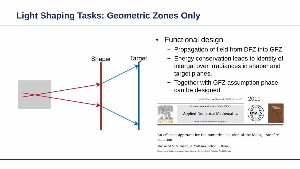
Light Shaping Tasks Geometric Zones Only
bull Functional designminus Propagation of field from DFZ into GFZminus Energy conservation leads to identity of
intergal over irradiances in shaper and target planes
minus Together with GFZ assumption phase can be designed
2011
Gaussian to Top-Hat (Non-paraxial)
Gaussian wavehigh NA (001)
input plane
reference plane
target plane
target irradiance
30mm
35mm
35mm2m
m
2mm
20mm
the output NA asymp 04
The Rayleigh lengths of the input Gaussian is 5556microm
Gaussian to Top-Hat (Non-paraxial) Phase Design via Meshes
mesh on reference plane
2mm
2mm
30m
m
30mm
mesh on target plane
Gaussian wavehigh NA (001)
input plane
reference plane
target plane
30mm2mm
2mm
20mm
Gaussian to Top-Hat (Non-paraxial) Functional Embodiment
irradiance at target plane
cross-section (normalized)
Gaussian wavehigh NA (001)
input plane
functional embodiment
target plane
30mm2mm
2mm
20mm
irradiance before the component
irradiance after the component
Gaussian to Top-Hat (Non-paraxial) Functional Embodiment
irradiance at target plane
cross-section (normalized)
Gaussian wavehigh NA (001)
input plane
functional embodiment
target plane
30mm2mm
2mm
20mm
irradiance before the component
irradiance after the component
Resolution of pattern limited by GFZ assumption and NA of system
Light Shaping Tasks Geometric Zones Only
Structural design altrnativesbullFreeform surface design (convergent minusiterative algorithm)HOE design (direct design)minus
bull Functional designminus Propagation of field from DFZ into GFZminus Energy conservation leads to identity of
intergal over irradiances in shaper and target planes
minus Together with GFZ assumption phase can be designed
Gaussian to Top-Hat (Non-paraxial) Freeform Surface
irradiance behind the surface
irradiance at target planeGaussian wavehigh NA (001)
freeform element
target plane
30mm2mm
2mm
20mm
cross-section (normalized)
Height Profile(2D Contour line)
Elliptical Gaussian to Top-Hat (Non-paraxial) Freeform Surface
irradiance behind the surface
irradiance at target planeGaussian wavehigh NA (001)
input plane target
plane
30mm2mm
2mm
20mm
freeform element
cross-section (normalized)
Height Profile(2D Contour line)
Plane Wave to Far Field Pattern (Non-paraxial)
plane wave
input plane
optical element
target plane
target irradiance distribution
100mm
150mm
150mm
14mm
Plane Wave to Far Field Pattern (Non-paraxial) Functional Design
-75
0
-150
75
150mm
-75 0-150 75 150mm
0
-15
15mm
0-15 15mm
mesh on input plane
mesh on target plane
plane wave
input plane
referenceplane
target plane
100mm14mm
Plane Wave to Far Field Pattern (Non-paraxial) Functional
irradiance at target plane(normalized)
error from target irradiance
plane wave
input plane
functional component
target plane
100mm14mm
Resolution of pattern limited by GFZ assumption
Plane Wave to Far Field Pattern (Non-paraxial) Freeform Surface
ray tracing
irradiance at target plane(normalized)
error from target irradianceHeight Profile
(2D Contour line)
Gaussian to Top-Hat (Paraxial) Freeform Surface
Gaussian wavehigh NA (001)
input plane target
plane
300mm
2mm
2mm
20mm
freeformelement
irradiance behind the surface
irradiance at target plane
cross-section (normalized)
Height Profile(2D Contour line)
Field is in slow diffractive field zone
Gaussian to Top-Hat (Paraxial) Freeform Surface
bull Because of paraxial field (slow beams) shaper is in DFZ and not GFZ
bull That results in slight diffractive effects which are not included in design
bull By subsequent iterative Fourier transform algorithm which takes DFZ into account that can be corrected
Gaussian to Top-Hat (Non-paraxial) HOE
Gaussian wavehigh NA (001) HOE
target plane
30mm2mm
2mm
20mm
-1order 0 order +1order
irradiance behind HOE
the output NA asymp 04
Gaussian to Top-Hat (Non-paraxial) HOE
ray tracing result with HOE (with the working order of -1 order)
HOEinputplane
target plane
-1 order
HOEinputplane
target plane
0 order
HOEinputplane
target plane
+1 order
Investigate Rayleigh Coefficient
-1order 0 order +1order
Ex Component behind HOE
cross-section profile result from Grating Toolbox
-1 o
rder
0 or
der
+1 o
rder
the Rayleight coefficient along the cross-section is compared with the result from Grating Toolbox
Modeling with Fourier Modal Method (FMM)
Gaussian to Top-Hat (Non-paraxial) HOE
Gaussian wavehigh NA (001) HOE
target plane
30mm2mm
2mm
20mm
-1order 0 order +1order
irradiance on target plane
Gaussian to Top-Hat (Non-paraxial) Lens + HOE
Gaussian wavehigh NA (001)
HOE target plane
30mm2mm
2mm
20mm
sphericallens
Gaussian to Top-Hat (Non-paraxial) Lens + HOE
Gaussian wavehigh NA (001)
HOE target plane
30mm2mm
2mm
20mm
sphericallens
wavefront behind spherical lens
the Peak-to-Valley wavefront error is 3583120582120582
wavefront error with respect to spherical wavefront
Gaussian to Top-Hat (Non-paraxial) Lens + HOE
The result irradiance on target plane is compared with the previous case without the lens
-1order 0 order +1order
without the lens
with the lens
Light Shaping Tasks Cases
Target in geometric field zone bull(GFZ)
bull Shaper in geometric field zone (GFZ)
Shaper Target
Light Shaping Tasks Gaussian to RingmodeShaper Target
Gaussian to Ringmode Refractive Approach (GFZ)Shaper Target
Gaussian to Ringmode Refractive Approach (GFZ)Shaper Target
Gaussian to Ringmode Diffractive Approach (DFZ)Vortex + Lens Target
DFZ
Gaussian to Ringmode Diffractive Approach (DFZ)Vortex + Lens Target
Diffractive light shaping by coherent superposition
Diffractive beam splitter and diffuser
Shaping by ldquoBeam ScanningrdquoTarget
Basic source mode eg Gaussian
Shaping by ldquoBeam Scanningrdquo
bull Beam splits at shaperbull Field behind shaper is in diffractive field zonebull Shaper is grating DOE
Shaper Target
Target pattern is ldquowrittenrdquo by scanned beam in target plane
Illustration of Deflection
Phase of transmission Intensity in target
Illustration of Deflection
Phase of transmission Intensity in target
Illustration of Deflection
Phase of transmission Intensity in target
Illustration of Deflection
Phase of transmission Intensity in target
Illustration of Deflection
Phase of transmission Intensity in target
Illustration of Deflection Sum
Phase of transmission Intensity in target
Basic Design Situations Splitting
bull Spots overlap in target patten diffractive diffuser
bull Spots in target pattern do not overlap diffractive beam splitter
Basic Design Situations Splitting
bull Spots overlap in target patten diffractive diffuser
Spots in target pattern do not bulloverlap diffractive beam splitter
Shaping by ldquoBeam Scanningrdquo
Amplitude Phase
Iterative Fourier Transform Algorithm
Advanced diffractive optics design techniques
Design technique (IFTA) implemented in VirtualLabtrade
Micro-structured surface profile
Fabricated at IAP University of Jena
Feature Sizes of Element
Feature sizeabout 400 nm
4 height levels
Optical Experiment
Jenaacutes sbquoSkylinelsquo
Comments on Diffuser Technology
Very flexible in light pattern generationbullRobust against adjustment problems bullCoherent light leads to speckle patternbullSize of speckle features can be adjusted by focusing systembullDiffusers work for partially coherent beams bullPartially coherent beams smooth the speckle pattern effect can be simulated bullwith VirtualLabtrade
Diffractive Optics Pattern Generation
Diffuser technology
Diffractive Optics Pattern Generation
Diffuser technology Design very chromatic
Source RGB
Solution by Integrated Diffractive Optics
wwwLightTranscom112
Far Field Propagation
Source Plane Wave RGB Transmission Regions
Waveguide Component
High NA Beam Splitter by Two DOElsquos
Parameter Value amp Unitnumber of orders 11 x 11order separation 1 x 1 degperiod 3035 x 3035 micrompixel size 690 x 690 nmdiscrete height levels 8material fused silica
surfaceprofile
paraxial beam splitter
Specification Second Beam Splitter
Parameter Value amp Unitnumber of orders 5 x 5order separation 11 x 11 degperiod 273 x 273 micrompixel size 130 x 130 nmdiscrete height levels 8material fused silica
surfaceprofile
high-NA beam splitter
Results Spot Diagram
spot diagram
combination of both beam splitter generate 55 x 55 order with 55x 55deg full
opening spread
a
Results Output Evaluation with FMM
Light shaping by lateral decomposition
Elementary cell array components
Array of Deflectors
Array of Deflectors
Deflection can be done by gratings prisms mirrors
TaskSystem Illustration
Cell Array Element
spherical wave(point source)
cell array structurebuilt up withbull prismsbull gratingsbull mirrors
Parameter Description Value amp Unittype RGB LEDemitter size 100 x 100 micromwavelength (473 532 635) nmpolarization right circularly polarized lightnumber of lateral modes 3 x 3Total number of lateral andspectral modes
27
Specification Light Source
Specification Cell Array
Parameter Value amp Unitnumber of cells 100 x 100cell size 125 x 125 micromarray aperture 125 x 125 mm
Results 3D System Ray Tracing
Results Grating Cells Array
spot
dia
gram
inte
nsity
pat
tern
(re
al c
olor
vie
w)
for grating cells array strong dispersion
effects occur
Results Prism Cells Array
spot
dia
gram
inte
nsity
pat
tern
(re
al c
olor
vie
w)
the dispersion is significantly reduced by
using prisms
Results Mirror Cells Array
spot
dia
gram
inte
nsity
pat
tern
(re
al c
olor
vie
w)
due to reflective approach no dispersion
effects occur
Light shaping by lateral decomposition
Lens and freeform array components
Array of Micro-optical Components
Lateral combination of elementary light shaping solutions
TaskSystem Illustration
50 mm Angular Spectrum (Far Field)
LED + collimation optic
aperiodic refractive beam shaper array (aBSA)
camera detector
Specs Light Source
spectrum model
fast and accurate modeling of a white bulllight LEDdesign and analysis an aperiodic bullrefractive beam shaper array to optimize a top hat intensity pattern
Highlightshere
Results Intensity Pattern (real color view)
aperiodic beam shaper array periodic microlens array
a
Summary
Introduction of a geometric branch of physical optics bullwith the help of the geometric Fourier transform Refractive and diffractive light shaping concepts bullfollow a unified theory in physical optics Classification of light shaping concepts dependent of bullpositions of shaper(s) and target in field zones Elementary shaping concepts can be combinedbull
Superposition in same area eg beam splitterminusLaterally combined eg cell arrayminus -type components
Further investigations on the basis of the unified bulltheory will reveal further concepts and deeper understanding of light shaping
bull Designs and simulations done with VirtualLab Fusion software

Gaussian to Top-Hat (Non-paraxial) Functional Embodiment
irradiance at target plane
cross-section (normalized)
Gaussian wavehigh NA (001)
input plane
functional embodiment
target plane
30mm2mm
2mm
20mm
irradiance before the component
irradiance after the component
Gaussian to Top-Hat (Non-paraxial) Functional Embodiment
irradiance at target plane
cross-section (normalized)
Gaussian wavehigh NA (001)
input plane
functional embodiment
target plane
30mm2mm
2mm
20mm
irradiance before the component
irradiance after the component
Resolution of pattern limited by GFZ assumption and NA of system
Light Shaping Tasks Geometric Zones Only
Structural design altrnativesbullFreeform surface design (convergent minusiterative algorithm)HOE design (direct design)minus
bull Functional designminus Propagation of field from DFZ into GFZminus Energy conservation leads to identity of
intergal over irradiances in shaper and target planes
minus Together with GFZ assumption phase can be designed
Gaussian to Top-Hat (Non-paraxial) Freeform Surface
irradiance behind the surface
irradiance at target planeGaussian wavehigh NA (001)
freeform element
target plane
30mm2mm
2mm
20mm
cross-section (normalized)
Height Profile(2D Contour line)
Elliptical Gaussian to Top-Hat (Non-paraxial) Freeform Surface
irradiance behind the surface
irradiance at target planeGaussian wavehigh NA (001)
input plane target
plane
30mm2mm
2mm
20mm
freeform element
cross-section (normalized)
Height Profile(2D Contour line)
Plane Wave to Far Field Pattern (Non-paraxial)
plane wave
input plane
optical element
target plane
target irradiance distribution
100mm
150mm
150mm
14mm
Plane Wave to Far Field Pattern (Non-paraxial) Functional Design
-75
0
-150
75
150mm
-75 0-150 75 150mm
0
-15
15mm
0-15 15mm
mesh on input plane
mesh on target plane
plane wave
input plane
referenceplane
target plane
100mm14mm
Plane Wave to Far Field Pattern (Non-paraxial) Functional
irradiance at target plane(normalized)
error from target irradiance
plane wave
input plane
functional component
target plane
100mm14mm
Resolution of pattern limited by GFZ assumption
Plane Wave to Far Field Pattern (Non-paraxial) Freeform Surface
ray tracing
irradiance at target plane(normalized)
error from target irradianceHeight Profile
(2D Contour line)
Gaussian to Top-Hat (Paraxial) Freeform Surface
Gaussian wavehigh NA (001)
input plane target
plane
300mm
2mm
2mm
20mm
freeformelement
irradiance behind the surface
irradiance at target plane
cross-section (normalized)
Height Profile(2D Contour line)
Field is in slow diffractive field zone
Gaussian to Top-Hat (Paraxial) Freeform Surface
bull Because of paraxial field (slow beams) shaper is in DFZ and not GFZ
bull That results in slight diffractive effects which are not included in design
bull By subsequent iterative Fourier transform algorithm which takes DFZ into account that can be corrected
Gaussian to Top-Hat (Non-paraxial) HOE
Gaussian wavehigh NA (001) HOE
target plane
30mm2mm
2mm
20mm
-1order 0 order +1order
irradiance behind HOE
the output NA asymp 04
Gaussian to Top-Hat (Non-paraxial) HOE
ray tracing result with HOE (with the working order of -1 order)
HOEinputplane
target plane
-1 order
HOEinputplane
target plane
0 order
HOEinputplane
target plane
+1 order
Investigate Rayleigh Coefficient
-1order 0 order +1order
Ex Component behind HOE
cross-section profile result from Grating Toolbox
-1 o
rder
0 or
der
+1 o
rder
the Rayleight coefficient along the cross-section is compared with the result from Grating Toolbox
Modeling with Fourier Modal Method (FMM)
Gaussian to Top-Hat (Non-paraxial) HOE
Gaussian wavehigh NA (001) HOE
target plane
30mm2mm
2mm
20mm
-1order 0 order +1order
irradiance on target plane
Gaussian to Top-Hat (Non-paraxial) Lens + HOE
Gaussian wavehigh NA (001)
HOE target plane
30mm2mm
2mm
20mm
sphericallens
Gaussian to Top-Hat (Non-paraxial) Lens + HOE
Gaussian wavehigh NA (001)
HOE target plane
30mm2mm
2mm
20mm
sphericallens
wavefront behind spherical lens
the Peak-to-Valley wavefront error is 3583120582120582
wavefront error with respect to spherical wavefront
Gaussian to Top-Hat (Non-paraxial) Lens + HOE
The result irradiance on target plane is compared with the previous case without the lens
-1order 0 order +1order
without the lens
with the lens
Light Shaping Tasks Cases
Target in geometric field zone bull(GFZ)
bull Shaper in geometric field zone (GFZ)
Shaper Target
Light Shaping Tasks Gaussian to RingmodeShaper Target
Gaussian to Ringmode Refractive Approach (GFZ)Shaper Target
Gaussian to Ringmode Refractive Approach (GFZ)Shaper Target
Gaussian to Ringmode Diffractive Approach (DFZ)Vortex + Lens Target
DFZ
Gaussian to Ringmode Diffractive Approach (DFZ)Vortex + Lens Target
Diffractive light shaping by coherent superposition
Diffractive beam splitter and diffuser
Shaping by ldquoBeam ScanningrdquoTarget
Basic source mode eg Gaussian
Shaping by ldquoBeam Scanningrdquo
bull Beam splits at shaperbull Field behind shaper is in diffractive field zonebull Shaper is grating DOE
Shaper Target
Target pattern is ldquowrittenrdquo by scanned beam in target plane
Illustration of Deflection
Phase of transmission Intensity in target
Illustration of Deflection
Phase of transmission Intensity in target
Illustration of Deflection
Phase of transmission Intensity in target
Illustration of Deflection
Phase of transmission Intensity in target
Illustration of Deflection
Phase of transmission Intensity in target
Illustration of Deflection Sum
Phase of transmission Intensity in target
Basic Design Situations Splitting
bull Spots overlap in target patten diffractive diffuser
bull Spots in target pattern do not overlap diffractive beam splitter
Basic Design Situations Splitting
bull Spots overlap in target patten diffractive diffuser
Spots in target pattern do not bulloverlap diffractive beam splitter
Shaping by ldquoBeam Scanningrdquo
Amplitude Phase
Iterative Fourier Transform Algorithm
Advanced diffractive optics design techniques
Design technique (IFTA) implemented in VirtualLabtrade
Micro-structured surface profile
Fabricated at IAP University of Jena
Feature Sizes of Element
Feature sizeabout 400 nm
4 height levels
Optical Experiment
Jenaacutes sbquoSkylinelsquo
Comments on Diffuser Technology
Very flexible in light pattern generationbullRobust against adjustment problems bullCoherent light leads to speckle patternbullSize of speckle features can be adjusted by focusing systembullDiffusers work for partially coherent beams bullPartially coherent beams smooth the speckle pattern effect can be simulated bullwith VirtualLabtrade
Diffractive Optics Pattern Generation
Diffuser technology
Diffractive Optics Pattern Generation
Diffuser technology Design very chromatic
Source RGB
Solution by Integrated Diffractive Optics
wwwLightTranscom112
Far Field Propagation
Source Plane Wave RGB Transmission Regions
Waveguide Component
High NA Beam Splitter by Two DOElsquos
Parameter Value amp Unitnumber of orders 11 x 11order separation 1 x 1 degperiod 3035 x 3035 micrompixel size 690 x 690 nmdiscrete height levels 8material fused silica
surfaceprofile
paraxial beam splitter
Specification Second Beam Splitter
Parameter Value amp Unitnumber of orders 5 x 5order separation 11 x 11 degperiod 273 x 273 micrompixel size 130 x 130 nmdiscrete height levels 8material fused silica
surfaceprofile
high-NA beam splitter
Results Spot Diagram
spot diagram
combination of both beam splitter generate 55 x 55 order with 55x 55deg full
opening spread
a
Results Output Evaluation with FMM
Light shaping by lateral decomposition
Elementary cell array components
Array of Deflectors
Array of Deflectors
Deflection can be done by gratings prisms mirrors
TaskSystem Illustration
Cell Array Element
spherical wave(point source)
cell array structurebuilt up withbull prismsbull gratingsbull mirrors
Parameter Description Value amp Unittype RGB LEDemitter size 100 x 100 micromwavelength (473 532 635) nmpolarization right circularly polarized lightnumber of lateral modes 3 x 3Total number of lateral andspectral modes
27
Specification Light Source
Specification Cell Array
Parameter Value amp Unitnumber of cells 100 x 100cell size 125 x 125 micromarray aperture 125 x 125 mm
Results 3D System Ray Tracing
Results Grating Cells Array
spot
dia
gram
inte
nsity
pat
tern
(re
al c
olor
vie
w)
for grating cells array strong dispersion
effects occur
Results Prism Cells Array
spot
dia
gram
inte
nsity
pat
tern
(re
al c
olor
vie
w)
the dispersion is significantly reduced by
using prisms
Results Mirror Cells Array
spot
dia
gram
inte
nsity
pat
tern
(re
al c
olor
vie
w)
due to reflective approach no dispersion
effects occur
Light shaping by lateral decomposition
Lens and freeform array components
Array of Micro-optical Components
Lateral combination of elementary light shaping solutions
TaskSystem Illustration
50 mm Angular Spectrum (Far Field)
LED + collimation optic
aperiodic refractive beam shaper array (aBSA)
camera detector
Specs Light Source
spectrum model
fast and accurate modeling of a white bulllight LEDdesign and analysis an aperiodic bullrefractive beam shaper array to optimize a top hat intensity pattern
Highlightshere
Results Intensity Pattern (real color view)
aperiodic beam shaper array periodic microlens array
a
Summary
Introduction of a geometric branch of physical optics bullwith the help of the geometric Fourier transform Refractive and diffractive light shaping concepts bullfollow a unified theory in physical optics Classification of light shaping concepts dependent of bullpositions of shaper(s) and target in field zones Elementary shaping concepts can be combinedbull
Superposition in same area eg beam splitterminusLaterally combined eg cell arrayminus -type components
Further investigations on the basis of the unified bulltheory will reveal further concepts and deeper understanding of light shaping
bull Designs and simulations done with VirtualLab Fusion software

Gaussian to Top-Hat (Non-paraxial) Functional Embodiment
irradiance at target plane
cross-section (normalized)
Gaussian wavehigh NA (001)
input plane
functional embodiment
target plane
30mm2mm
2mm
20mm
irradiance before the component
irradiance after the component
Resolution of pattern limited by GFZ assumption and NA of system
Light Shaping Tasks Geometric Zones Only
Structural design altrnativesbullFreeform surface design (convergent minusiterative algorithm)HOE design (direct design)minus
bull Functional designminus Propagation of field from DFZ into GFZminus Energy conservation leads to identity of
intergal over irradiances in shaper and target planes
minus Together with GFZ assumption phase can be designed
Gaussian to Top-Hat (Non-paraxial) Freeform Surface
irradiance behind the surface
irradiance at target planeGaussian wavehigh NA (001)
freeform element
target plane
30mm2mm
2mm
20mm
cross-section (normalized)
Height Profile(2D Contour line)
Elliptical Gaussian to Top-Hat (Non-paraxial) Freeform Surface
irradiance behind the surface
irradiance at target planeGaussian wavehigh NA (001)
input plane target
plane
30mm2mm
2mm
20mm
freeform element
cross-section (normalized)
Height Profile(2D Contour line)
Plane Wave to Far Field Pattern (Non-paraxial)
plane wave
input plane
optical element
target plane
target irradiance distribution
100mm
150mm
150mm
14mm
Plane Wave to Far Field Pattern (Non-paraxial) Functional Design
-75
0
-150
75
150mm
-75 0-150 75 150mm
0
-15
15mm
0-15 15mm
mesh on input plane
mesh on target plane
plane wave
input plane
referenceplane
target plane
100mm14mm
Plane Wave to Far Field Pattern (Non-paraxial) Functional
irradiance at target plane(normalized)
error from target irradiance
plane wave
input plane
functional component
target plane
100mm14mm
Resolution of pattern limited by GFZ assumption
Plane Wave to Far Field Pattern (Non-paraxial) Freeform Surface
ray tracing
irradiance at target plane(normalized)
error from target irradianceHeight Profile
(2D Contour line)
Gaussian to Top-Hat (Paraxial) Freeform Surface
Gaussian wavehigh NA (001)
input plane target
plane
300mm
2mm
2mm
20mm
freeformelement
irradiance behind the surface
irradiance at target plane
cross-section (normalized)
Height Profile(2D Contour line)
Field is in slow diffractive field zone
Gaussian to Top-Hat (Paraxial) Freeform Surface
bull Because of paraxial field (slow beams) shaper is in DFZ and not GFZ
bull That results in slight diffractive effects which are not included in design
bull By subsequent iterative Fourier transform algorithm which takes DFZ into account that can be corrected
Gaussian to Top-Hat (Non-paraxial) HOE
Gaussian wavehigh NA (001) HOE
target plane
30mm2mm
2mm
20mm
-1order 0 order +1order
irradiance behind HOE
the output NA asymp 04
Gaussian to Top-Hat (Non-paraxial) HOE
ray tracing result with HOE (with the working order of -1 order)
HOEinputplane
target plane
-1 order
HOEinputplane
target plane
0 order
HOEinputplane
target plane
+1 order
Investigate Rayleigh Coefficient
-1order 0 order +1order
Ex Component behind HOE
cross-section profile result from Grating Toolbox
-1 o
rder
0 or
der
+1 o
rder
the Rayleight coefficient along the cross-section is compared with the result from Grating Toolbox
Modeling with Fourier Modal Method (FMM)
Gaussian to Top-Hat (Non-paraxial) HOE
Gaussian wavehigh NA (001) HOE
target plane
30mm2mm
2mm
20mm
-1order 0 order +1order
irradiance on target plane
Gaussian to Top-Hat (Non-paraxial) Lens + HOE
Gaussian wavehigh NA (001)
HOE target plane
30mm2mm
2mm
20mm
sphericallens
Gaussian to Top-Hat (Non-paraxial) Lens + HOE
Gaussian wavehigh NA (001)
HOE target plane
30mm2mm
2mm
20mm
sphericallens
wavefront behind spherical lens
the Peak-to-Valley wavefront error is 3583120582120582
wavefront error with respect to spherical wavefront
Gaussian to Top-Hat (Non-paraxial) Lens + HOE
The result irradiance on target plane is compared with the previous case without the lens
-1order 0 order +1order
without the lens
with the lens
Light Shaping Tasks Cases
Target in geometric field zone bull(GFZ)
bull Shaper in geometric field zone (GFZ)
Shaper Target
Light Shaping Tasks Gaussian to RingmodeShaper Target
Gaussian to Ringmode Refractive Approach (GFZ)Shaper Target
Gaussian to Ringmode Refractive Approach (GFZ)Shaper Target
Gaussian to Ringmode Diffractive Approach (DFZ)Vortex + Lens Target
DFZ
Gaussian to Ringmode Diffractive Approach (DFZ)Vortex + Lens Target
Diffractive light shaping by coherent superposition
Diffractive beam splitter and diffuser
Shaping by ldquoBeam ScanningrdquoTarget
Basic source mode eg Gaussian
Shaping by ldquoBeam Scanningrdquo
bull Beam splits at shaperbull Field behind shaper is in diffractive field zonebull Shaper is grating DOE
Shaper Target
Target pattern is ldquowrittenrdquo by scanned beam in target plane
Illustration of Deflection
Phase of transmission Intensity in target
Illustration of Deflection
Phase of transmission Intensity in target
Illustration of Deflection
Phase of transmission Intensity in target
Illustration of Deflection
Phase of transmission Intensity in target
Illustration of Deflection
Phase of transmission Intensity in target
Illustration of Deflection Sum
Phase of transmission Intensity in target
Basic Design Situations Splitting
bull Spots overlap in target patten diffractive diffuser
bull Spots in target pattern do not overlap diffractive beam splitter
Basic Design Situations Splitting
bull Spots overlap in target patten diffractive diffuser
Spots in target pattern do not bulloverlap diffractive beam splitter
Shaping by ldquoBeam Scanningrdquo
Amplitude Phase
Iterative Fourier Transform Algorithm
Advanced diffractive optics design techniques
Design technique (IFTA) implemented in VirtualLabtrade
Micro-structured surface profile
Fabricated at IAP University of Jena
Feature Sizes of Element
Feature sizeabout 400 nm
4 height levels
Optical Experiment
Jenaacutes sbquoSkylinelsquo
Comments on Diffuser Technology
Very flexible in light pattern generationbullRobust against adjustment problems bullCoherent light leads to speckle patternbullSize of speckle features can be adjusted by focusing systembullDiffusers work for partially coherent beams bullPartially coherent beams smooth the speckle pattern effect can be simulated bullwith VirtualLabtrade
Diffractive Optics Pattern Generation
Diffuser technology
Diffractive Optics Pattern Generation
Diffuser technology Design very chromatic
Source RGB
Solution by Integrated Diffractive Optics
wwwLightTranscom112
Far Field Propagation
Source Plane Wave RGB Transmission Regions
Waveguide Component
High NA Beam Splitter by Two DOElsquos
Parameter Value amp Unitnumber of orders 11 x 11order separation 1 x 1 degperiod 3035 x 3035 micrompixel size 690 x 690 nmdiscrete height levels 8material fused silica
surfaceprofile
paraxial beam splitter
Specification Second Beam Splitter
Parameter Value amp Unitnumber of orders 5 x 5order separation 11 x 11 degperiod 273 x 273 micrompixel size 130 x 130 nmdiscrete height levels 8material fused silica
surfaceprofile
high-NA beam splitter
Results Spot Diagram
spot diagram
combination of both beam splitter generate 55 x 55 order with 55x 55deg full
opening spread
a
Results Output Evaluation with FMM
Light shaping by lateral decomposition
Elementary cell array components
Array of Deflectors
Array of Deflectors
Deflection can be done by gratings prisms mirrors
TaskSystem Illustration
Cell Array Element
spherical wave(point source)
cell array structurebuilt up withbull prismsbull gratingsbull mirrors
Parameter Description Value amp Unittype RGB LEDemitter size 100 x 100 micromwavelength (473 532 635) nmpolarization right circularly polarized lightnumber of lateral modes 3 x 3Total number of lateral andspectral modes
27
Specification Light Source
Specification Cell Array
Parameter Value amp Unitnumber of cells 100 x 100cell size 125 x 125 micromarray aperture 125 x 125 mm
Results 3D System Ray Tracing
Results Grating Cells Array
spot
dia
gram
inte
nsity
pat
tern
(re
al c
olor
vie
w)
for grating cells array strong dispersion
effects occur
Results Prism Cells Array
spot
dia
gram
inte
nsity
pat
tern
(re
al c
olor
vie
w)
the dispersion is significantly reduced by
using prisms
Results Mirror Cells Array
spot
dia
gram
inte
nsity
pat
tern
(re
al c
olor
vie
w)
due to reflective approach no dispersion
effects occur
Light shaping by lateral decomposition
Lens and freeform array components
Array of Micro-optical Components
Lateral combination of elementary light shaping solutions
TaskSystem Illustration
50 mm Angular Spectrum (Far Field)
LED + collimation optic
aperiodic refractive beam shaper array (aBSA)
camera detector
Specs Light Source
spectrum model
fast and accurate modeling of a white bulllight LEDdesign and analysis an aperiodic bullrefractive beam shaper array to optimize a top hat intensity pattern
Highlightshere
Results Intensity Pattern (real color view)
aperiodic beam shaper array periodic microlens array
a
Summary
Introduction of a geometric branch of physical optics bullwith the help of the geometric Fourier transform Refractive and diffractive light shaping concepts bullfollow a unified theory in physical optics Classification of light shaping concepts dependent of bullpositions of shaper(s) and target in field zones Elementary shaping concepts can be combinedbull
Superposition in same area eg beam splitterminusLaterally combined eg cell arrayminus -type components
Further investigations on the basis of the unified bulltheory will reveal further concepts and deeper understanding of light shaping
bull Designs and simulations done with VirtualLab Fusion software
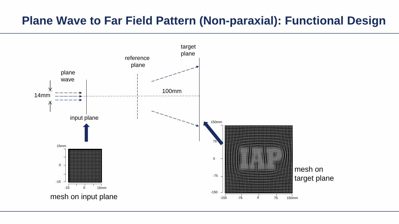

Gaussian to Top-Hat (Paraxial) Freeform Surface
Gaussian wavehigh NA (001)
input plane target
plane
300mm
2mm
2mm
20mm
freeformelement
irradiance behind the surface
irradiance at target plane
cross-section (normalized)
Height Profile(2D Contour line)
Field is in slow diffractive field zone
Gaussian to Top-Hat (Paraxial) Freeform Surface
bull Because of paraxial field (slow beams) shaper is in DFZ and not GFZ
bull That results in slight diffractive effects which are not included in design
bull By subsequent iterative Fourier transform algorithm which takes DFZ into account that can be corrected
Gaussian to Top-Hat (Non-paraxial) HOE
Gaussian wavehigh NA (001) HOE
target plane
30mm2mm
2mm
20mm
-1order 0 order +1order
irradiance behind HOE
the output NA asymp 04
Gaussian to Top-Hat (Non-paraxial) HOE
ray tracing result with HOE (with the working order of -1 order)
HOEinputplane
target plane
-1 order
HOEinputplane
target plane
0 order
HOEinputplane
target plane
+1 order
Investigate Rayleigh Coefficient
-1order 0 order +1order
Ex Component behind HOE
cross-section profile result from Grating Toolbox
-1 o
rder
0 or
der
+1 o
rder
the Rayleight coefficient along the cross-section is compared with the result from Grating Toolbox
Modeling with Fourier Modal Method (FMM)
Gaussian to Top-Hat (Non-paraxial) HOE
Gaussian wavehigh NA (001) HOE
target plane
30mm2mm
2mm
20mm
-1order 0 order +1order
irradiance on target plane
Gaussian to Top-Hat (Non-paraxial) Lens + HOE
Gaussian wavehigh NA (001)
HOE target plane
30mm2mm
2mm
20mm
sphericallens
Gaussian to Top-Hat (Non-paraxial) Lens + HOE
Gaussian wavehigh NA (001)
HOE target plane
30mm2mm
2mm
20mm
sphericallens
wavefront behind spherical lens
the Peak-to-Valley wavefront error is 3583120582120582
wavefront error with respect to spherical wavefront
Gaussian to Top-Hat (Non-paraxial) Lens + HOE
The result irradiance on target plane is compared with the previous case without the lens
-1order 0 order +1order
without the lens
with the lens
Light Shaping Tasks Cases
Target in geometric field zone bull(GFZ)
bull Shaper in geometric field zone (GFZ)
Shaper Target
Light Shaping Tasks Gaussian to RingmodeShaper Target
Gaussian to Ringmode Refractive Approach (GFZ)Shaper Target
Gaussian to Ringmode Refractive Approach (GFZ)Shaper Target
Gaussian to Ringmode Diffractive Approach (DFZ)Vortex + Lens Target
DFZ
Gaussian to Ringmode Diffractive Approach (DFZ)Vortex + Lens Target
Diffractive light shaping by coherent superposition
Diffractive beam splitter and diffuser
Shaping by ldquoBeam ScanningrdquoTarget
Basic source mode eg Gaussian
Shaping by ldquoBeam Scanningrdquo
bull Beam splits at shaperbull Field behind shaper is in diffractive field zonebull Shaper is grating DOE
Shaper Target
Target pattern is ldquowrittenrdquo by scanned beam in target plane
Illustration of Deflection
Phase of transmission Intensity in target
Illustration of Deflection
Phase of transmission Intensity in target
Illustration of Deflection
Phase of transmission Intensity in target
Illustration of Deflection
Phase of transmission Intensity in target
Illustration of Deflection
Phase of transmission Intensity in target
Illustration of Deflection Sum
Phase of transmission Intensity in target
Basic Design Situations Splitting
bull Spots overlap in target patten diffractive diffuser
bull Spots in target pattern do not overlap diffractive beam splitter
Basic Design Situations Splitting
bull Spots overlap in target patten diffractive diffuser
Spots in target pattern do not bulloverlap diffractive beam splitter
Shaping by ldquoBeam Scanningrdquo
Amplitude Phase
Iterative Fourier Transform Algorithm
Advanced diffractive optics design techniques
Design technique (IFTA) implemented in VirtualLabtrade
Micro-structured surface profile
Fabricated at IAP University of Jena
Feature Sizes of Element
Feature sizeabout 400 nm
4 height levels
Optical Experiment
Jenaacutes sbquoSkylinelsquo
Comments on Diffuser Technology
Very flexible in light pattern generationbullRobust against adjustment problems bullCoherent light leads to speckle patternbullSize of speckle features can be adjusted by focusing systembullDiffusers work for partially coherent beams bullPartially coherent beams smooth the speckle pattern effect can be simulated bullwith VirtualLabtrade
Diffractive Optics Pattern Generation
Diffuser technology
Diffractive Optics Pattern Generation
Diffuser technology Design very chromatic
Source RGB
Solution by Integrated Diffractive Optics
wwwLightTranscom112
Far Field Propagation
Source Plane Wave RGB Transmission Regions
Waveguide Component
High NA Beam Splitter by Two DOElsquos
Parameter Value amp Unitnumber of orders 11 x 11order separation 1 x 1 degperiod 3035 x 3035 micrompixel size 690 x 690 nmdiscrete height levels 8material fused silica
surfaceprofile
paraxial beam splitter
Specification Second Beam Splitter
Parameter Value amp Unitnumber of orders 5 x 5order separation 11 x 11 degperiod 273 x 273 micrompixel size 130 x 130 nmdiscrete height levels 8material fused silica
surfaceprofile
high-NA beam splitter
Results Spot Diagram
spot diagram
combination of both beam splitter generate 55 x 55 order with 55x 55deg full
opening spread
a
Results Output Evaluation with FMM
Light shaping by lateral decomposition
Elementary cell array components
Array of Deflectors
Array of Deflectors
Deflection can be done by gratings prisms mirrors
TaskSystem Illustration
Cell Array Element
spherical wave(point source)
cell array structurebuilt up withbull prismsbull gratingsbull mirrors
Parameter Description Value amp Unittype RGB LEDemitter size 100 x 100 micromwavelength (473 532 635) nmpolarization right circularly polarized lightnumber of lateral modes 3 x 3Total number of lateral andspectral modes
27
Specification Light Source
Specification Cell Array
Parameter Value amp Unitnumber of cells 100 x 100cell size 125 x 125 micromarray aperture 125 x 125 mm
Results 3D System Ray Tracing
Results Grating Cells Array
spot
dia
gram
inte
nsity
pat
tern
(re
al c
olor
vie
w)
for grating cells array strong dispersion
effects occur
Results Prism Cells Array
spot
dia
gram
inte
nsity
pat
tern
(re
al c
olor
vie
w)
the dispersion is significantly reduced by
using prisms
Results Mirror Cells Array
spot
dia
gram
inte
nsity
pat
tern
(re
al c
olor
vie
w)
due to reflective approach no dispersion
effects occur
Light shaping by lateral decomposition
Lens and freeform array components
Array of Micro-optical Components
Lateral combination of elementary light shaping solutions
TaskSystem Illustration
50 mm Angular Spectrum (Far Field)
LED + collimation optic
aperiodic refractive beam shaper array (aBSA)
camera detector
Specs Light Source
spectrum model
fast and accurate modeling of a white bulllight LEDdesign and analysis an aperiodic bullrefractive beam shaper array to optimize a top hat intensity pattern
Highlightshere
Results Intensity Pattern (real color view)
aperiodic beam shaper array periodic microlens array
a
Summary
Introduction of a geometric branch of physical optics bullwith the help of the geometric Fourier transform Refractive and diffractive light shaping concepts bullfollow a unified theory in physical optics Classification of light shaping concepts dependent of bullpositions of shaper(s) and target in field zones Elementary shaping concepts can be combinedbull
Superposition in same area eg beam splitterminusLaterally combined eg cell arrayminus -type components
Further investigations on the basis of the unified bulltheory will reveal further concepts and deeper understanding of light shaping
bull Designs and simulations done with VirtualLab Fusion software

Gaussian to Top-Hat (Paraxial) Freeform Surface
bull Because of paraxial field (slow beams) shaper is in DFZ and not GFZ
bull That results in slight diffractive effects which are not included in design
bull By subsequent iterative Fourier transform algorithm which takes DFZ into account that can be corrected
Gaussian to Top-Hat (Non-paraxial) HOE
Gaussian wavehigh NA (001) HOE
target plane
30mm2mm
2mm
20mm
-1order 0 order +1order
irradiance behind HOE
the output NA asymp 04
Gaussian to Top-Hat (Non-paraxial) HOE
ray tracing result with HOE (with the working order of -1 order)
HOEinputplane
target plane
-1 order
HOEinputplane
target plane
0 order
HOEinputplane
target plane
+1 order
Investigate Rayleigh Coefficient
-1order 0 order +1order
Ex Component behind HOE
cross-section profile result from Grating Toolbox
-1 o
rder
0 or
der
+1 o
rder
the Rayleight coefficient along the cross-section is compared with the result from Grating Toolbox
Modeling with Fourier Modal Method (FMM)
Gaussian to Top-Hat (Non-paraxial) HOE
Gaussian wavehigh NA (001) HOE
target plane
30mm2mm
2mm
20mm
-1order 0 order +1order
irradiance on target plane
Gaussian to Top-Hat (Non-paraxial) Lens + HOE
Gaussian wavehigh NA (001)
HOE target plane
30mm2mm
2mm
20mm
sphericallens
Gaussian to Top-Hat (Non-paraxial) Lens + HOE
Gaussian wavehigh NA (001)
HOE target plane
30mm2mm
2mm
20mm
sphericallens
wavefront behind spherical lens
the Peak-to-Valley wavefront error is 3583120582120582
wavefront error with respect to spherical wavefront
Gaussian to Top-Hat (Non-paraxial) Lens + HOE
The result irradiance on target plane is compared with the previous case without the lens
-1order 0 order +1order
without the lens
with the lens
Light Shaping Tasks Cases
Target in geometric field zone bull(GFZ)
bull Shaper in geometric field zone (GFZ)
Shaper Target
Light Shaping Tasks Gaussian to RingmodeShaper Target
Gaussian to Ringmode Refractive Approach (GFZ)Shaper Target
Gaussian to Ringmode Refractive Approach (GFZ)Shaper Target
Gaussian to Ringmode Diffractive Approach (DFZ)Vortex + Lens Target
DFZ
Gaussian to Ringmode Diffractive Approach (DFZ)Vortex + Lens Target
Diffractive light shaping by coherent superposition
Diffractive beam splitter and diffuser
Shaping by ldquoBeam ScanningrdquoTarget
Basic source mode eg Gaussian
Shaping by ldquoBeam Scanningrdquo
bull Beam splits at shaperbull Field behind shaper is in diffractive field zonebull Shaper is grating DOE
Shaper Target
Target pattern is ldquowrittenrdquo by scanned beam in target plane
Illustration of Deflection
Phase of transmission Intensity in target
Illustration of Deflection
Phase of transmission Intensity in target
Illustration of Deflection
Phase of transmission Intensity in target
Illustration of Deflection
Phase of transmission Intensity in target
Illustration of Deflection
Phase of transmission Intensity in target
Illustration of Deflection Sum
Phase of transmission Intensity in target
Basic Design Situations Splitting
bull Spots overlap in target patten diffractive diffuser
bull Spots in target pattern do not overlap diffractive beam splitter
Basic Design Situations Splitting
bull Spots overlap in target patten diffractive diffuser
Spots in target pattern do not bulloverlap diffractive beam splitter
Shaping by ldquoBeam Scanningrdquo
Amplitude Phase
Iterative Fourier Transform Algorithm
Advanced diffractive optics design techniques
Design technique (IFTA) implemented in VirtualLabtrade
Micro-structured surface profile
Fabricated at IAP University of Jena
Feature Sizes of Element
Feature sizeabout 400 nm
4 height levels
Optical Experiment
Jenaacutes sbquoSkylinelsquo
Comments on Diffuser Technology
Very flexible in light pattern generationbullRobust against adjustment problems bullCoherent light leads to speckle patternbullSize of speckle features can be adjusted by focusing systembullDiffusers work for partially coherent beams bullPartially coherent beams smooth the speckle pattern effect can be simulated bullwith VirtualLabtrade
Diffractive Optics Pattern Generation
Diffuser technology
Diffractive Optics Pattern Generation
Diffuser technology Design very chromatic
Source RGB
Solution by Integrated Diffractive Optics
wwwLightTranscom112
Far Field Propagation
Source Plane Wave RGB Transmission Regions
Waveguide Component
High NA Beam Splitter by Two DOElsquos
Parameter Value amp Unitnumber of orders 11 x 11order separation 1 x 1 degperiod 3035 x 3035 micrompixel size 690 x 690 nmdiscrete height levels 8material fused silica
surfaceprofile
paraxial beam splitter
Specification Second Beam Splitter
Parameter Value amp Unitnumber of orders 5 x 5order separation 11 x 11 degperiod 273 x 273 micrompixel size 130 x 130 nmdiscrete height levels 8material fused silica
surfaceprofile
high-NA beam splitter
Results Spot Diagram
spot diagram
combination of both beam splitter generate 55 x 55 order with 55x 55deg full
opening spread
a
Results Output Evaluation with FMM
Light shaping by lateral decomposition
Elementary cell array components
Array of Deflectors
Array of Deflectors
Deflection can be done by gratings prisms mirrors
TaskSystem Illustration
Cell Array Element
spherical wave(point source)
cell array structurebuilt up withbull prismsbull gratingsbull mirrors
Parameter Description Value amp Unittype RGB LEDemitter size 100 x 100 micromwavelength (473 532 635) nmpolarization right circularly polarized lightnumber of lateral modes 3 x 3Total number of lateral andspectral modes
27
Specification Light Source
Specification Cell Array
Parameter Value amp Unitnumber of cells 100 x 100cell size 125 x 125 micromarray aperture 125 x 125 mm
Results 3D System Ray Tracing
Results Grating Cells Array
spot
dia
gram
inte
nsity
pat
tern
(re
al c
olor
vie
w)
for grating cells array strong dispersion
effects occur
Results Prism Cells Array
spot
dia
gram
inte
nsity
pat
tern
(re
al c
olor
vie
w)
the dispersion is significantly reduced by
using prisms
Results Mirror Cells Array
spot
dia
gram
inte
nsity
pat
tern
(re
al c
olor
vie
w)
due to reflective approach no dispersion
effects occur
Light shaping by lateral decomposition
Lens and freeform array components
Array of Micro-optical Components
Lateral combination of elementary light shaping solutions
TaskSystem Illustration
50 mm Angular Spectrum (Far Field)
LED + collimation optic
aperiodic refractive beam shaper array (aBSA)
camera detector
Specs Light Source
spectrum model
fast and accurate modeling of a white bulllight LEDdesign and analysis an aperiodic bullrefractive beam shaper array to optimize a top hat intensity pattern
Highlightshere
Results Intensity Pattern (real color view)
aperiodic beam shaper array periodic microlens array
a
Summary
Introduction of a geometric branch of physical optics bullwith the help of the geometric Fourier transform Refractive and diffractive light shaping concepts bullfollow a unified theory in physical optics Classification of light shaping concepts dependent of bullpositions of shaper(s) and target in field zones Elementary shaping concepts can be combinedbull
Superposition in same area eg beam splitterminusLaterally combined eg cell arrayminus -type components
Further investigations on the basis of the unified bulltheory will reveal further concepts and deeper understanding of light shaping
bull Designs and simulations done with VirtualLab Fusion software

Gaussian to Top-Hat (Non-paraxial) HOE
Gaussian wavehigh NA (001) HOE
target plane
30mm2mm
2mm
20mm
-1order 0 order +1order
irradiance behind HOE
the output NA asymp 04
Gaussian to Top-Hat (Non-paraxial) HOE
ray tracing result with HOE (with the working order of -1 order)
HOEinputplane
target plane
-1 order
HOEinputplane
target plane
0 order
HOEinputplane
target plane
+1 order
Investigate Rayleigh Coefficient
-1order 0 order +1order
Ex Component behind HOE
cross-section profile result from Grating Toolbox
-1 o
rder
0 or
der
+1 o
rder
the Rayleight coefficient along the cross-section is compared with the result from Grating Toolbox
Modeling with Fourier Modal Method (FMM)
Gaussian to Top-Hat (Non-paraxial) HOE
Gaussian wavehigh NA (001) HOE
target plane
30mm2mm
2mm
20mm
-1order 0 order +1order
irradiance on target plane
Gaussian to Top-Hat (Non-paraxial) Lens + HOE
Gaussian wavehigh NA (001)
HOE target plane
30mm2mm
2mm
20mm
sphericallens
Gaussian to Top-Hat (Non-paraxial) Lens + HOE
Gaussian wavehigh NA (001)
HOE target plane
30mm2mm
2mm
20mm
sphericallens
wavefront behind spherical lens
the Peak-to-Valley wavefront error is 3583120582120582
wavefront error with respect to spherical wavefront
Gaussian to Top-Hat (Non-paraxial) Lens + HOE
The result irradiance on target plane is compared with the previous case without the lens
-1order 0 order +1order
without the lens
with the lens
Light Shaping Tasks Cases
Target in geometric field zone bull(GFZ)
bull Shaper in geometric field zone (GFZ)
Shaper Target
Light Shaping Tasks Gaussian to RingmodeShaper Target
Gaussian to Ringmode Refractive Approach (GFZ)Shaper Target
Gaussian to Ringmode Refractive Approach (GFZ)Shaper Target
Gaussian to Ringmode Diffractive Approach (DFZ)Vortex + Lens Target
DFZ
Gaussian to Ringmode Diffractive Approach (DFZ)Vortex + Lens Target
Diffractive light shaping by coherent superposition
Diffractive beam splitter and diffuser
Shaping by ldquoBeam ScanningrdquoTarget
Basic source mode eg Gaussian
Shaping by ldquoBeam Scanningrdquo
bull Beam splits at shaperbull Field behind shaper is in diffractive field zonebull Shaper is grating DOE
Shaper Target
Target pattern is ldquowrittenrdquo by scanned beam in target plane
Illustration of Deflection
Phase of transmission Intensity in target
Illustration of Deflection
Phase of transmission Intensity in target
Illustration of Deflection
Phase of transmission Intensity in target
Illustration of Deflection
Phase of transmission Intensity in target
Illustration of Deflection
Phase of transmission Intensity in target
Illustration of Deflection Sum
Phase of transmission Intensity in target
Basic Design Situations Splitting
bull Spots overlap in target patten diffractive diffuser
bull Spots in target pattern do not overlap diffractive beam splitter
Basic Design Situations Splitting
bull Spots overlap in target patten diffractive diffuser
Spots in target pattern do not bulloverlap diffractive beam splitter
Shaping by ldquoBeam Scanningrdquo
Amplitude Phase
Iterative Fourier Transform Algorithm
Advanced diffractive optics design techniques
Design technique (IFTA) implemented in VirtualLabtrade
Micro-structured surface profile
Fabricated at IAP University of Jena
Feature Sizes of Element
Feature sizeabout 400 nm
4 height levels
Optical Experiment
Jenaacutes sbquoSkylinelsquo
Comments on Diffuser Technology
Very flexible in light pattern generationbullRobust against adjustment problems bullCoherent light leads to speckle patternbullSize of speckle features can be adjusted by focusing systembullDiffusers work for partially coherent beams bullPartially coherent beams smooth the speckle pattern effect can be simulated bullwith VirtualLabtrade
Diffractive Optics Pattern Generation
Diffuser technology
Diffractive Optics Pattern Generation
Diffuser technology Design very chromatic
Source RGB
Solution by Integrated Diffractive Optics
wwwLightTranscom112
Far Field Propagation
Source Plane Wave RGB Transmission Regions
Waveguide Component
High NA Beam Splitter by Two DOElsquos
Parameter Value amp Unitnumber of orders 11 x 11order separation 1 x 1 degperiod 3035 x 3035 micrompixel size 690 x 690 nmdiscrete height levels 8material fused silica
surfaceprofile
paraxial beam splitter
Specification Second Beam Splitter
Parameter Value amp Unitnumber of orders 5 x 5order separation 11 x 11 degperiod 273 x 273 micrompixel size 130 x 130 nmdiscrete height levels 8material fused silica
surfaceprofile
high-NA beam splitter
Results Spot Diagram
spot diagram
combination of both beam splitter generate 55 x 55 order with 55x 55deg full
opening spread
a
Results Output Evaluation with FMM
Light shaping by lateral decomposition
Elementary cell array components
Array of Deflectors
Array of Deflectors
Deflection can be done by gratings prisms mirrors
TaskSystem Illustration
Cell Array Element
spherical wave(point source)
cell array structurebuilt up withbull prismsbull gratingsbull mirrors
Parameter Description Value amp Unittype RGB LEDemitter size 100 x 100 micromwavelength (473 532 635) nmpolarization right circularly polarized lightnumber of lateral modes 3 x 3Total number of lateral andspectral modes
27
Specification Light Source
Specification Cell Array
Parameter Value amp Unitnumber of cells 100 x 100cell size 125 x 125 micromarray aperture 125 x 125 mm
Results 3D System Ray Tracing
Results Grating Cells Array
spot
dia
gram
inte
nsity
pat
tern
(re
al c
olor
vie
w)
for grating cells array strong dispersion
effects occur
Results Prism Cells Array
spot
dia
gram
inte
nsity
pat
tern
(re
al c
olor
vie
w)
the dispersion is significantly reduced by
using prisms
Results Mirror Cells Array
spot
dia
gram
inte
nsity
pat
tern
(re
al c
olor
vie
w)
due to reflective approach no dispersion
effects occur
Light shaping by lateral decomposition
Lens and freeform array components
Array of Micro-optical Components
Lateral combination of elementary light shaping solutions
TaskSystem Illustration
50 mm Angular Spectrum (Far Field)
LED + collimation optic
aperiodic refractive beam shaper array (aBSA)
camera detector
Specs Light Source
spectrum model
fast and accurate modeling of a white bulllight LEDdesign and analysis an aperiodic bullrefractive beam shaper array to optimize a top hat intensity pattern
Highlightshere
Results Intensity Pattern (real color view)
aperiodic beam shaper array periodic microlens array
a
Summary
Introduction of a geometric branch of physical optics bullwith the help of the geometric Fourier transform Refractive and diffractive light shaping concepts bullfollow a unified theory in physical optics Classification of light shaping concepts dependent of bullpositions of shaper(s) and target in field zones Elementary shaping concepts can be combinedbull
Superposition in same area eg beam splitterminusLaterally combined eg cell arrayminus -type components
Further investigations on the basis of the unified bulltheory will reveal further concepts and deeper understanding of light shaping
bull Designs and simulations done with VirtualLab Fusion software

Gaussian to Top-Hat (Non-paraxial) HOE
ray tracing result with HOE (with the working order of -1 order)
HOEinputplane
target plane
-1 order
HOEinputplane
target plane
0 order
HOEinputplane
target plane
+1 order
Investigate Rayleigh Coefficient
-1order 0 order +1order
Ex Component behind HOE
cross-section profile result from Grating Toolbox
-1 o
rder
0 or
der
+1 o
rder
the Rayleight coefficient along the cross-section is compared with the result from Grating Toolbox
Modeling with Fourier Modal Method (FMM)
Gaussian to Top-Hat (Non-paraxial) HOE
Gaussian wavehigh NA (001) HOE
target plane
30mm2mm
2mm
20mm
-1order 0 order +1order
irradiance on target plane
Gaussian to Top-Hat (Non-paraxial) Lens + HOE
Gaussian wavehigh NA (001)
HOE target plane
30mm2mm
2mm
20mm
sphericallens
Gaussian to Top-Hat (Non-paraxial) Lens + HOE
Gaussian wavehigh NA (001)
HOE target plane
30mm2mm
2mm
20mm
sphericallens
wavefront behind spherical lens
the Peak-to-Valley wavefront error is 3583120582120582
wavefront error with respect to spherical wavefront
Gaussian to Top-Hat (Non-paraxial) Lens + HOE
The result irradiance on target plane is compared with the previous case without the lens
-1order 0 order +1order
without the lens
with the lens
Light Shaping Tasks Cases
Target in geometric field zone bull(GFZ)
bull Shaper in geometric field zone (GFZ)
Shaper Target
Light Shaping Tasks Gaussian to RingmodeShaper Target
Gaussian to Ringmode Refractive Approach (GFZ)Shaper Target
Gaussian to Ringmode Refractive Approach (GFZ)Shaper Target
Gaussian to Ringmode Diffractive Approach (DFZ)Vortex + Lens Target
DFZ
Gaussian to Ringmode Diffractive Approach (DFZ)Vortex + Lens Target
Diffractive light shaping by coherent superposition
Diffractive beam splitter and diffuser
Shaping by ldquoBeam ScanningrdquoTarget
Basic source mode eg Gaussian
Shaping by ldquoBeam Scanningrdquo
bull Beam splits at shaperbull Field behind shaper is in diffractive field zonebull Shaper is grating DOE
Shaper Target
Target pattern is ldquowrittenrdquo by scanned beam in target plane
Illustration of Deflection
Phase of transmission Intensity in target
Illustration of Deflection
Phase of transmission Intensity in target
Illustration of Deflection
Phase of transmission Intensity in target
Illustration of Deflection
Phase of transmission Intensity in target
Illustration of Deflection
Phase of transmission Intensity in target
Illustration of Deflection Sum
Phase of transmission Intensity in target
Basic Design Situations Splitting
bull Spots overlap in target patten diffractive diffuser
bull Spots in target pattern do not overlap diffractive beam splitter
Basic Design Situations Splitting
bull Spots overlap in target patten diffractive diffuser
Spots in target pattern do not bulloverlap diffractive beam splitter
Shaping by ldquoBeam Scanningrdquo
Amplitude Phase
Iterative Fourier Transform Algorithm
Advanced diffractive optics design techniques
Design technique (IFTA) implemented in VirtualLabtrade
Micro-structured surface profile
Fabricated at IAP University of Jena
Feature Sizes of Element
Feature sizeabout 400 nm
4 height levels
Optical Experiment
Jenaacutes sbquoSkylinelsquo
Comments on Diffuser Technology
Very flexible in light pattern generationbullRobust against adjustment problems bullCoherent light leads to speckle patternbullSize of speckle features can be adjusted by focusing systembullDiffusers work for partially coherent beams bullPartially coherent beams smooth the speckle pattern effect can be simulated bullwith VirtualLabtrade
Diffractive Optics Pattern Generation
Diffuser technology
Diffractive Optics Pattern Generation
Diffuser technology Design very chromatic
Source RGB
Solution by Integrated Diffractive Optics
wwwLightTranscom112
Far Field Propagation
Source Plane Wave RGB Transmission Regions
Waveguide Component
High NA Beam Splitter by Two DOElsquos
Parameter Value amp Unitnumber of orders 11 x 11order separation 1 x 1 degperiod 3035 x 3035 micrompixel size 690 x 690 nmdiscrete height levels 8material fused silica
surfaceprofile
paraxial beam splitter
Specification Second Beam Splitter
Parameter Value amp Unitnumber of orders 5 x 5order separation 11 x 11 degperiod 273 x 273 micrompixel size 130 x 130 nmdiscrete height levels 8material fused silica
surfaceprofile
high-NA beam splitter
Results Spot Diagram
spot diagram
combination of both beam splitter generate 55 x 55 order with 55x 55deg full
opening spread
a
Results Output Evaluation with FMM
Light shaping by lateral decomposition
Elementary cell array components
Array of Deflectors
Array of Deflectors
Deflection can be done by gratings prisms mirrors
TaskSystem Illustration
Cell Array Element
spherical wave(point source)
cell array structurebuilt up withbull prismsbull gratingsbull mirrors
Parameter Description Value amp Unittype RGB LEDemitter size 100 x 100 micromwavelength (473 532 635) nmpolarization right circularly polarized lightnumber of lateral modes 3 x 3Total number of lateral andspectral modes
27
Specification Light Source
Specification Cell Array
Parameter Value amp Unitnumber of cells 100 x 100cell size 125 x 125 micromarray aperture 125 x 125 mm
Results 3D System Ray Tracing
Results Grating Cells Array
spot
dia
gram
inte
nsity
pat
tern
(re
al c
olor
vie
w)
for grating cells array strong dispersion
effects occur
Results Prism Cells Array
spot
dia
gram
inte
nsity
pat
tern
(re
al c
olor
vie
w)
the dispersion is significantly reduced by
using prisms
Results Mirror Cells Array
spot
dia
gram
inte
nsity
pat
tern
(re
al c
olor
vie
w)
due to reflective approach no dispersion
effects occur
Light shaping by lateral decomposition
Lens and freeform array components
Array of Micro-optical Components
Lateral combination of elementary light shaping solutions
TaskSystem Illustration
50 mm Angular Spectrum (Far Field)
LED + collimation optic
aperiodic refractive beam shaper array (aBSA)
camera detector
Specs Light Source
spectrum model
fast and accurate modeling of a white bulllight LEDdesign and analysis an aperiodic bullrefractive beam shaper array to optimize a top hat intensity pattern
Highlightshere
Results Intensity Pattern (real color view)
aperiodic beam shaper array periodic microlens array
a
Summary
Introduction of a geometric branch of physical optics bullwith the help of the geometric Fourier transform Refractive and diffractive light shaping concepts bullfollow a unified theory in physical optics Classification of light shaping concepts dependent of bullpositions of shaper(s) and target in field zones Elementary shaping concepts can be combinedbull
Superposition in same area eg beam splitterminusLaterally combined eg cell arrayminus -type components
Further investigations on the basis of the unified bulltheory will reveal further concepts and deeper understanding of light shaping
bull Designs and simulations done with VirtualLab Fusion software
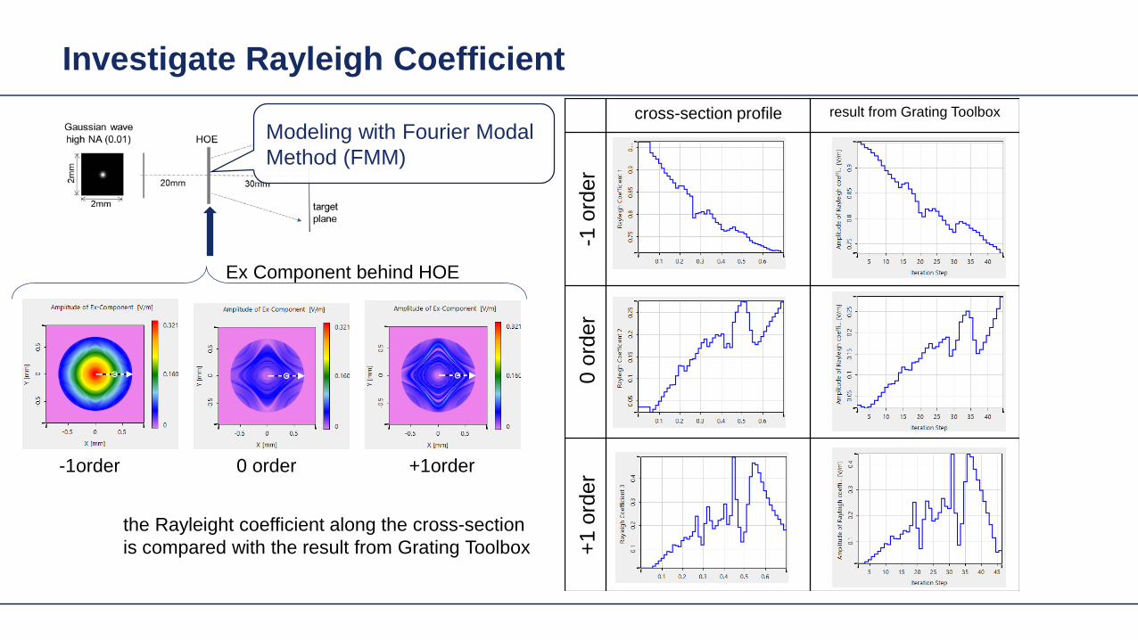

Gaussian to Top-Hat (Non-paraxial) Lens + HOE
Gaussian wavehigh NA (001)
HOE target plane
30mm2mm
2mm
20mm
sphericallens
Gaussian to Top-Hat (Non-paraxial) Lens + HOE
Gaussian wavehigh NA (001)
HOE target plane
30mm2mm
2mm
20mm
sphericallens
wavefront behind spherical lens
the Peak-to-Valley wavefront error is 3583120582120582
wavefront error with respect to spherical wavefront
Gaussian to Top-Hat (Non-paraxial) Lens + HOE
The result irradiance on target plane is compared with the previous case without the lens
-1order 0 order +1order
without the lens
with the lens
Light Shaping Tasks Cases
Target in geometric field zone bull(GFZ)
bull Shaper in geometric field zone (GFZ)
Shaper Target
Light Shaping Tasks Gaussian to RingmodeShaper Target
Gaussian to Ringmode Refractive Approach (GFZ)Shaper Target
Gaussian to Ringmode Refractive Approach (GFZ)Shaper Target
Gaussian to Ringmode Diffractive Approach (DFZ)Vortex + Lens Target
DFZ
Gaussian to Ringmode Diffractive Approach (DFZ)Vortex + Lens Target
Diffractive light shaping by coherent superposition
Diffractive beam splitter and diffuser
Shaping by ldquoBeam ScanningrdquoTarget
Basic source mode eg Gaussian
Shaping by ldquoBeam Scanningrdquo
bull Beam splits at shaperbull Field behind shaper is in diffractive field zonebull Shaper is grating DOE
Shaper Target
Target pattern is ldquowrittenrdquo by scanned beam in target plane
Illustration of Deflection
Phase of transmission Intensity in target
Illustration of Deflection
Phase of transmission Intensity in target
Illustration of Deflection
Phase of transmission Intensity in target
Illustration of Deflection
Phase of transmission Intensity in target
Illustration of Deflection
Phase of transmission Intensity in target
Illustration of Deflection Sum
Phase of transmission Intensity in target
Basic Design Situations Splitting
bull Spots overlap in target patten diffractive diffuser
bull Spots in target pattern do not overlap diffractive beam splitter
Basic Design Situations Splitting
bull Spots overlap in target patten diffractive diffuser
Spots in target pattern do not bulloverlap diffractive beam splitter
Shaping by ldquoBeam Scanningrdquo
Amplitude Phase
Iterative Fourier Transform Algorithm
Advanced diffractive optics design techniques
Design technique (IFTA) implemented in VirtualLabtrade
Micro-structured surface profile
Fabricated at IAP University of Jena
Feature Sizes of Element
Feature sizeabout 400 nm
4 height levels
Optical Experiment
Jenaacutes sbquoSkylinelsquo
Comments on Diffuser Technology
Very flexible in light pattern generationbullRobust against adjustment problems bullCoherent light leads to speckle patternbullSize of speckle features can be adjusted by focusing systembullDiffusers work for partially coherent beams bullPartially coherent beams smooth the speckle pattern effect can be simulated bullwith VirtualLabtrade
Diffractive Optics Pattern Generation
Diffuser technology
Diffractive Optics Pattern Generation
Diffuser technology Design very chromatic
Source RGB
Solution by Integrated Diffractive Optics
wwwLightTranscom112
Far Field Propagation
Source Plane Wave RGB Transmission Regions
Waveguide Component
High NA Beam Splitter by Two DOElsquos
Parameter Value amp Unitnumber of orders 11 x 11order separation 1 x 1 degperiod 3035 x 3035 micrompixel size 690 x 690 nmdiscrete height levels 8material fused silica
surfaceprofile
paraxial beam splitter
Specification Second Beam Splitter
Parameter Value amp Unitnumber of orders 5 x 5order separation 11 x 11 degperiod 273 x 273 micrompixel size 130 x 130 nmdiscrete height levels 8material fused silica
surfaceprofile
high-NA beam splitter
Results Spot Diagram
spot diagram
combination of both beam splitter generate 55 x 55 order with 55x 55deg full
opening spread
a
Results Output Evaluation with FMM
Light shaping by lateral decomposition
Elementary cell array components
Array of Deflectors
Array of Deflectors
Deflection can be done by gratings prisms mirrors
TaskSystem Illustration
Cell Array Element
spherical wave(point source)
cell array structurebuilt up withbull prismsbull gratingsbull mirrors
Parameter Description Value amp Unittype RGB LEDemitter size 100 x 100 micromwavelength (473 532 635) nmpolarization right circularly polarized lightnumber of lateral modes 3 x 3Total number of lateral andspectral modes
27
Specification Light Source
Specification Cell Array
Parameter Value amp Unitnumber of cells 100 x 100cell size 125 x 125 micromarray aperture 125 x 125 mm
Results 3D System Ray Tracing
Results Grating Cells Array
spot
dia
gram
inte
nsity
pat
tern
(re
al c
olor
vie
w)
for grating cells array strong dispersion
effects occur
Results Prism Cells Array
spot
dia
gram
inte
nsity
pat
tern
(re
al c
olor
vie
w)
the dispersion is significantly reduced by
using prisms
Results Mirror Cells Array
spot
dia
gram
inte
nsity
pat
tern
(re
al c
olor
vie
w)
due to reflective approach no dispersion
effects occur
Light shaping by lateral decomposition
Lens and freeform array components
Array of Micro-optical Components
Lateral combination of elementary light shaping solutions
TaskSystem Illustration
50 mm Angular Spectrum (Far Field)
LED + collimation optic
aperiodic refractive beam shaper array (aBSA)
camera detector
Specs Light Source
spectrum model
fast and accurate modeling of a white bulllight LEDdesign and analysis an aperiodic bullrefractive beam shaper array to optimize a top hat intensity pattern
Highlightshere
Results Intensity Pattern (real color view)
aperiodic beam shaper array periodic microlens array
a
Summary
Introduction of a geometric branch of physical optics bullwith the help of the geometric Fourier transform Refractive and diffractive light shaping concepts bullfollow a unified theory in physical optics Classification of light shaping concepts dependent of bullpositions of shaper(s) and target in field zones Elementary shaping concepts can be combinedbull
Superposition in same area eg beam splitterminusLaterally combined eg cell arrayminus -type components
Further investigations on the basis of the unified bulltheory will reveal further concepts and deeper understanding of light shaping
bull Designs and simulations done with VirtualLab Fusion software
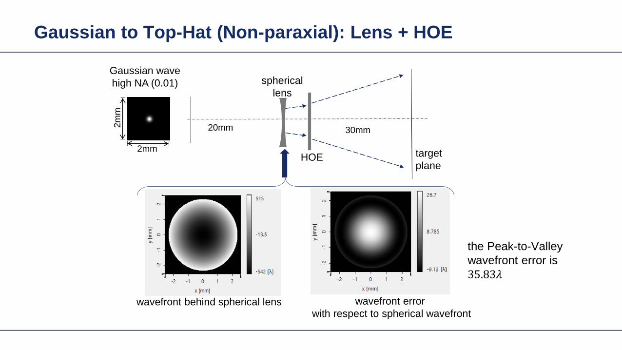
Gaussian to Top-Hat (Non-paraxial) Lens + HOE
Gaussian wavehigh NA (001)
HOE target plane
30mm2mm
2mm
20mm
sphericallens
wavefront behind spherical lens
the Peak-to-Valley wavefront error is 3583120582120582
wavefront error with respect to spherical wavefront
Gaussian to Top-Hat (Non-paraxial) Lens + HOE
The result irradiance on target plane is compared with the previous case without the lens
-1order 0 order +1order
without the lens
with the lens
Light Shaping Tasks Cases
Target in geometric field zone bull(GFZ)
bull Shaper in geometric field zone (GFZ)
Shaper Target
Light Shaping Tasks Gaussian to RingmodeShaper Target
Gaussian to Ringmode Refractive Approach (GFZ)Shaper Target
Gaussian to Ringmode Refractive Approach (GFZ)Shaper Target
Gaussian to Ringmode Diffractive Approach (DFZ)Vortex + Lens Target
DFZ
Gaussian to Ringmode Diffractive Approach (DFZ)Vortex + Lens Target
Diffractive light shaping by coherent superposition
Diffractive beam splitter and diffuser
Shaping by ldquoBeam ScanningrdquoTarget
Basic source mode eg Gaussian
Shaping by ldquoBeam Scanningrdquo
bull Beam splits at shaperbull Field behind shaper is in diffractive field zonebull Shaper is grating DOE
Shaper Target
Target pattern is ldquowrittenrdquo by scanned beam in target plane
Illustration of Deflection
Phase of transmission Intensity in target
Illustration of Deflection
Phase of transmission Intensity in target
Illustration of Deflection
Phase of transmission Intensity in target
Illustration of Deflection
Phase of transmission Intensity in target
Illustration of Deflection
Phase of transmission Intensity in target
Illustration of Deflection Sum
Phase of transmission Intensity in target
Basic Design Situations Splitting
bull Spots overlap in target patten diffractive diffuser
bull Spots in target pattern do not overlap diffractive beam splitter
Basic Design Situations Splitting
bull Spots overlap in target patten diffractive diffuser
Spots in target pattern do not bulloverlap diffractive beam splitter
Shaping by ldquoBeam Scanningrdquo
Amplitude Phase
Iterative Fourier Transform Algorithm
Advanced diffractive optics design techniques
Design technique (IFTA) implemented in VirtualLabtrade
Micro-structured surface profile
Fabricated at IAP University of Jena
Feature Sizes of Element
Feature sizeabout 400 nm
4 height levels
Optical Experiment
Jenaacutes sbquoSkylinelsquo
Comments on Diffuser Technology
Very flexible in light pattern generationbullRobust against adjustment problems bullCoherent light leads to speckle patternbullSize of speckle features can be adjusted by focusing systembullDiffusers work for partially coherent beams bullPartially coherent beams smooth the speckle pattern effect can be simulated bullwith VirtualLabtrade
Diffractive Optics Pattern Generation
Diffuser technology
Diffractive Optics Pattern Generation
Diffuser technology Design very chromatic
Source RGB
Solution by Integrated Diffractive Optics
wwwLightTranscom112
Far Field Propagation
Source Plane Wave RGB Transmission Regions
Waveguide Component
High NA Beam Splitter by Two DOElsquos
Parameter Value amp Unitnumber of orders 11 x 11order separation 1 x 1 degperiod 3035 x 3035 micrompixel size 690 x 690 nmdiscrete height levels 8material fused silica
surfaceprofile
paraxial beam splitter
Specification Second Beam Splitter
Parameter Value amp Unitnumber of orders 5 x 5order separation 11 x 11 degperiod 273 x 273 micrompixel size 130 x 130 nmdiscrete height levels 8material fused silica
surfaceprofile
high-NA beam splitter
Results Spot Diagram
spot diagram
combination of both beam splitter generate 55 x 55 order with 55x 55deg full
opening spread
a
Results Output Evaluation with FMM
Light shaping by lateral decomposition
Elementary cell array components
Array of Deflectors
Array of Deflectors
Deflection can be done by gratings prisms mirrors
TaskSystem Illustration
Cell Array Element
spherical wave(point source)
cell array structurebuilt up withbull prismsbull gratingsbull mirrors
Parameter Description Value amp Unittype RGB LEDemitter size 100 x 100 micromwavelength (473 532 635) nmpolarization right circularly polarized lightnumber of lateral modes 3 x 3Total number of lateral andspectral modes
27
Specification Light Source
Specification Cell Array
Parameter Value amp Unitnumber of cells 100 x 100cell size 125 x 125 micromarray aperture 125 x 125 mm
Results 3D System Ray Tracing
Results Grating Cells Array
spot
dia
gram
inte
nsity
pat
tern
(re
al c
olor
vie
w)
for grating cells array strong dispersion
effects occur
Results Prism Cells Array
spot
dia
gram
inte
nsity
pat
tern
(re
al c
olor
vie
w)
the dispersion is significantly reduced by
using prisms
Results Mirror Cells Array
spot
dia
gram
inte
nsity
pat
tern
(re
al c
olor
vie
w)
due to reflective approach no dispersion
effects occur
Light shaping by lateral decomposition
Lens and freeform array components
Array of Micro-optical Components
Lateral combination of elementary light shaping solutions
TaskSystem Illustration
50 mm Angular Spectrum (Far Field)
LED + collimation optic
aperiodic refractive beam shaper array (aBSA)
camera detector
Specs Light Source
spectrum model
fast and accurate modeling of a white bulllight LEDdesign and analysis an aperiodic bullrefractive beam shaper array to optimize a top hat intensity pattern
Highlightshere
Results Intensity Pattern (real color view)
aperiodic beam shaper array periodic microlens array
a
Summary
Introduction of a geometric branch of physical optics bullwith the help of the geometric Fourier transform Refractive and diffractive light shaping concepts bullfollow a unified theory in physical optics Classification of light shaping concepts dependent of bullpositions of shaper(s) and target in field zones Elementary shaping concepts can be combinedbull
Superposition in same area eg beam splitterminusLaterally combined eg cell arrayminus -type components
Further investigations on the basis of the unified bulltheory will reveal further concepts and deeper understanding of light shaping
bull Designs and simulations done with VirtualLab Fusion software

Gaussian to Top-Hat (Non-paraxial) Lens + HOE
The result irradiance on target plane is compared with the previous case without the lens
-1order 0 order +1order
without the lens
with the lens
Light Shaping Tasks Cases
Target in geometric field zone bull(GFZ)
bull Shaper in geometric field zone (GFZ)
Shaper Target
Light Shaping Tasks Gaussian to RingmodeShaper Target
Gaussian to Ringmode Refractive Approach (GFZ)Shaper Target
Gaussian to Ringmode Refractive Approach (GFZ)Shaper Target
Gaussian to Ringmode Diffractive Approach (DFZ)Vortex + Lens Target
DFZ
Gaussian to Ringmode Diffractive Approach (DFZ)Vortex + Lens Target
Diffractive light shaping by coherent superposition
Diffractive beam splitter and diffuser
Shaping by ldquoBeam ScanningrdquoTarget
Basic source mode eg Gaussian
Shaping by ldquoBeam Scanningrdquo
bull Beam splits at shaperbull Field behind shaper is in diffractive field zonebull Shaper is grating DOE
Shaper Target
Target pattern is ldquowrittenrdquo by scanned beam in target plane
Illustration of Deflection
Phase of transmission Intensity in target
Illustration of Deflection
Phase of transmission Intensity in target
Illustration of Deflection
Phase of transmission Intensity in target
Illustration of Deflection
Phase of transmission Intensity in target
Illustration of Deflection
Phase of transmission Intensity in target
Illustration of Deflection Sum
Phase of transmission Intensity in target
Basic Design Situations Splitting
bull Spots overlap in target patten diffractive diffuser
bull Spots in target pattern do not overlap diffractive beam splitter
Basic Design Situations Splitting
bull Spots overlap in target patten diffractive diffuser
Spots in target pattern do not bulloverlap diffractive beam splitter
Shaping by ldquoBeam Scanningrdquo
Amplitude Phase
Iterative Fourier Transform Algorithm
Advanced diffractive optics design techniques
Design technique (IFTA) implemented in VirtualLabtrade
Micro-structured surface profile
Fabricated at IAP University of Jena
Feature Sizes of Element
Feature sizeabout 400 nm
4 height levels
Optical Experiment
Jenaacutes sbquoSkylinelsquo
Comments on Diffuser Technology
Very flexible in light pattern generationbullRobust against adjustment problems bullCoherent light leads to speckle patternbullSize of speckle features can be adjusted by focusing systembullDiffusers work for partially coherent beams bullPartially coherent beams smooth the speckle pattern effect can be simulated bullwith VirtualLabtrade
Diffractive Optics Pattern Generation
Diffuser technology
Diffractive Optics Pattern Generation
Diffuser technology Design very chromatic
Source RGB
Solution by Integrated Diffractive Optics
wwwLightTranscom112
Far Field Propagation
Source Plane Wave RGB Transmission Regions
Waveguide Component
High NA Beam Splitter by Two DOElsquos
Parameter Value amp Unitnumber of orders 11 x 11order separation 1 x 1 degperiod 3035 x 3035 micrompixel size 690 x 690 nmdiscrete height levels 8material fused silica
surfaceprofile
paraxial beam splitter
Specification Second Beam Splitter
Parameter Value amp Unitnumber of orders 5 x 5order separation 11 x 11 degperiod 273 x 273 micrompixel size 130 x 130 nmdiscrete height levels 8material fused silica
surfaceprofile
high-NA beam splitter
Results Spot Diagram
spot diagram
combination of both beam splitter generate 55 x 55 order with 55x 55deg full
opening spread
a
Results Output Evaluation with FMM
Light shaping by lateral decomposition
Elementary cell array components
Array of Deflectors
Array of Deflectors
Deflection can be done by gratings prisms mirrors
TaskSystem Illustration
Cell Array Element
spherical wave(point source)
cell array structurebuilt up withbull prismsbull gratingsbull mirrors
Parameter Description Value amp Unittype RGB LEDemitter size 100 x 100 micromwavelength (473 532 635) nmpolarization right circularly polarized lightnumber of lateral modes 3 x 3Total number of lateral andspectral modes
27
Specification Light Source
Specification Cell Array
Parameter Value amp Unitnumber of cells 100 x 100cell size 125 x 125 micromarray aperture 125 x 125 mm
Results 3D System Ray Tracing
Results Grating Cells Array
spot
dia
gram
inte
nsity
pat
tern
(re
al c
olor
vie
w)
for grating cells array strong dispersion
effects occur
Results Prism Cells Array
spot
dia
gram
inte
nsity
pat
tern
(re
al c
olor
vie
w)
the dispersion is significantly reduced by
using prisms
Results Mirror Cells Array
spot
dia
gram
inte
nsity
pat
tern
(re
al c
olor
vie
w)
due to reflective approach no dispersion
effects occur
Light shaping by lateral decomposition
Lens and freeform array components
Array of Micro-optical Components
Lateral combination of elementary light shaping solutions
TaskSystem Illustration
50 mm Angular Spectrum (Far Field)
LED + collimation optic
aperiodic refractive beam shaper array (aBSA)
camera detector
Specs Light Source
spectrum model
fast and accurate modeling of a white bulllight LEDdesign and analysis an aperiodic bullrefractive beam shaper array to optimize a top hat intensity pattern
Highlightshere
Results Intensity Pattern (real color view)
aperiodic beam shaper array periodic microlens array
a
Summary
Introduction of a geometric branch of physical optics bullwith the help of the geometric Fourier transform Refractive and diffractive light shaping concepts bullfollow a unified theory in physical optics Classification of light shaping concepts dependent of bullpositions of shaper(s) and target in field zones Elementary shaping concepts can be combinedbull
Superposition in same area eg beam splitterminusLaterally combined eg cell arrayminus -type components
Further investigations on the basis of the unified bulltheory will reveal further concepts and deeper understanding of light shaping
bull Designs and simulations done with VirtualLab Fusion software
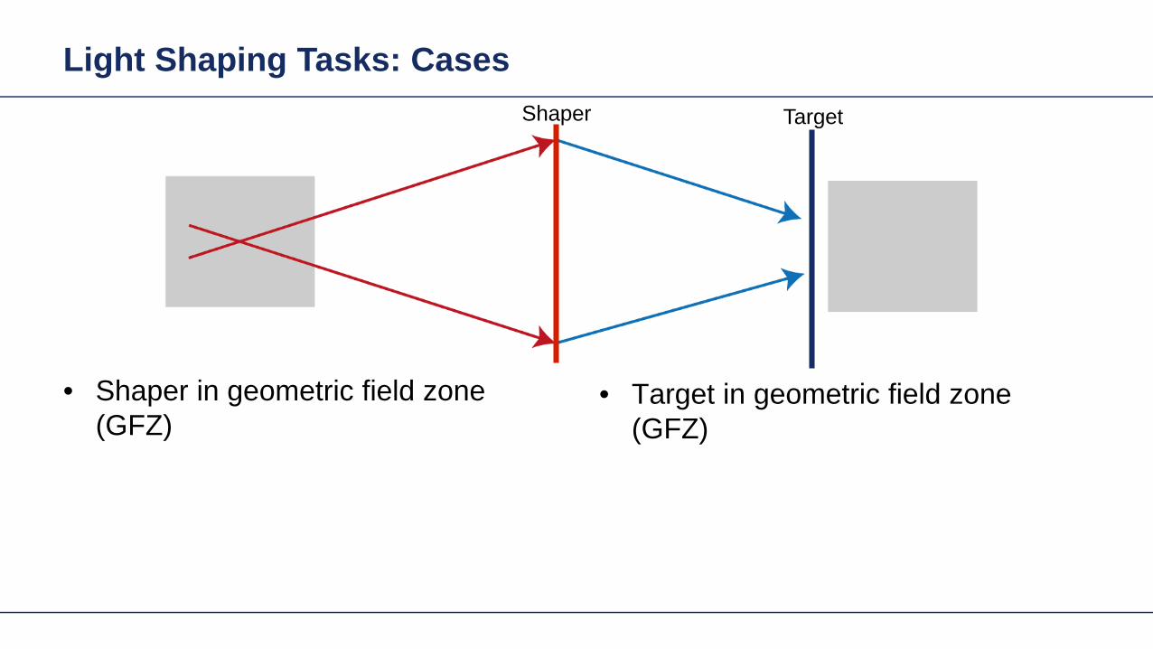

Gaussian to Ringmode Refractive Approach (GFZ)Shaper Target
Gaussian to Ringmode Refractive Approach (GFZ)Shaper Target
Gaussian to Ringmode Diffractive Approach (DFZ)Vortex + Lens Target
DFZ
Gaussian to Ringmode Diffractive Approach (DFZ)Vortex + Lens Target
Diffractive light shaping by coherent superposition
Diffractive beam splitter and diffuser
Shaping by ldquoBeam ScanningrdquoTarget
Basic source mode eg Gaussian
Shaping by ldquoBeam Scanningrdquo
bull Beam splits at shaperbull Field behind shaper is in diffractive field zonebull Shaper is grating DOE
Shaper Target
Target pattern is ldquowrittenrdquo by scanned beam in target plane
Illustration of Deflection
Phase of transmission Intensity in target
Illustration of Deflection
Phase of transmission Intensity in target
Illustration of Deflection
Phase of transmission Intensity in target
Illustration of Deflection
Phase of transmission Intensity in target
Illustration of Deflection
Phase of transmission Intensity in target
Illustration of Deflection Sum
Phase of transmission Intensity in target
Basic Design Situations Splitting
bull Spots overlap in target patten diffractive diffuser
bull Spots in target pattern do not overlap diffractive beam splitter
Basic Design Situations Splitting
bull Spots overlap in target patten diffractive diffuser
Spots in target pattern do not bulloverlap diffractive beam splitter
Shaping by ldquoBeam Scanningrdquo
Amplitude Phase
Iterative Fourier Transform Algorithm
Advanced diffractive optics design techniques
Design technique (IFTA) implemented in VirtualLabtrade
Micro-structured surface profile
Fabricated at IAP University of Jena
Feature Sizes of Element
Feature sizeabout 400 nm
4 height levels
Optical Experiment
Jenaacutes sbquoSkylinelsquo
Comments on Diffuser Technology
Very flexible in light pattern generationbullRobust against adjustment problems bullCoherent light leads to speckle patternbullSize of speckle features can be adjusted by focusing systembullDiffusers work for partially coherent beams bullPartially coherent beams smooth the speckle pattern effect can be simulated bullwith VirtualLabtrade
Diffractive Optics Pattern Generation
Diffuser technology
Diffractive Optics Pattern Generation
Diffuser technology Design very chromatic
Source RGB
Solution by Integrated Diffractive Optics
wwwLightTranscom112
Far Field Propagation
Source Plane Wave RGB Transmission Regions
Waveguide Component
High NA Beam Splitter by Two DOElsquos
Parameter Value amp Unitnumber of orders 11 x 11order separation 1 x 1 degperiod 3035 x 3035 micrompixel size 690 x 690 nmdiscrete height levels 8material fused silica
surfaceprofile
paraxial beam splitter
Specification Second Beam Splitter
Parameter Value amp Unitnumber of orders 5 x 5order separation 11 x 11 degperiod 273 x 273 micrompixel size 130 x 130 nmdiscrete height levels 8material fused silica
surfaceprofile
high-NA beam splitter
Results Spot Diagram
spot diagram
combination of both beam splitter generate 55 x 55 order with 55x 55deg full
opening spread
a
Results Output Evaluation with FMM
Light shaping by lateral decomposition
Elementary cell array components
Array of Deflectors
Array of Deflectors
Deflection can be done by gratings prisms mirrors
TaskSystem Illustration
Cell Array Element
spherical wave(point source)
cell array structurebuilt up withbull prismsbull gratingsbull mirrors
Parameter Description Value amp Unittype RGB LEDemitter size 100 x 100 micromwavelength (473 532 635) nmpolarization right circularly polarized lightnumber of lateral modes 3 x 3Total number of lateral andspectral modes
27
Specification Light Source
Specification Cell Array
Parameter Value amp Unitnumber of cells 100 x 100cell size 125 x 125 micromarray aperture 125 x 125 mm
Results 3D System Ray Tracing
Results Grating Cells Array
spot
dia
gram
inte
nsity
pat
tern
(re
al c
olor
vie
w)
for grating cells array strong dispersion
effects occur
Results Prism Cells Array
spot
dia
gram
inte
nsity
pat
tern
(re
al c
olor
vie
w)
the dispersion is significantly reduced by
using prisms
Results Mirror Cells Array
spot
dia
gram
inte
nsity
pat
tern
(re
al c
olor
vie
w)
due to reflective approach no dispersion
effects occur
Light shaping by lateral decomposition
Lens and freeform array components
Array of Micro-optical Components
Lateral combination of elementary light shaping solutions
TaskSystem Illustration
50 mm Angular Spectrum (Far Field)
LED + collimation optic
aperiodic refractive beam shaper array (aBSA)
camera detector
Specs Light Source
spectrum model
fast and accurate modeling of a white bulllight LEDdesign and analysis an aperiodic bullrefractive beam shaper array to optimize a top hat intensity pattern
Highlightshere
Results Intensity Pattern (real color view)
aperiodic beam shaper array periodic microlens array
a
Summary
Introduction of a geometric branch of physical optics bullwith the help of the geometric Fourier transform Refractive and diffractive light shaping concepts bullfollow a unified theory in physical optics Classification of light shaping concepts dependent of bullpositions of shaper(s) and target in field zones Elementary shaping concepts can be combinedbull
Superposition in same area eg beam splitterminusLaterally combined eg cell arrayminus -type components
Further investigations on the basis of the unified bulltheory will reveal further concepts and deeper understanding of light shaping
bull Designs and simulations done with VirtualLab Fusion software

Gaussian to Ringmode Refractive Approach (GFZ)Shaper Target
Gaussian to Ringmode Diffractive Approach (DFZ)Vortex + Lens Target
DFZ
Gaussian to Ringmode Diffractive Approach (DFZ)Vortex + Lens Target
Diffractive light shaping by coherent superposition
Diffractive beam splitter and diffuser
Shaping by ldquoBeam ScanningrdquoTarget
Basic source mode eg Gaussian
Shaping by ldquoBeam Scanningrdquo
bull Beam splits at shaperbull Field behind shaper is in diffractive field zonebull Shaper is grating DOE
Shaper Target
Target pattern is ldquowrittenrdquo by scanned beam in target plane
Illustration of Deflection
Phase of transmission Intensity in target
Illustration of Deflection
Phase of transmission Intensity in target
Illustration of Deflection
Phase of transmission Intensity in target
Illustration of Deflection
Phase of transmission Intensity in target
Illustration of Deflection
Phase of transmission Intensity in target
Illustration of Deflection Sum
Phase of transmission Intensity in target
Basic Design Situations Splitting
bull Spots overlap in target patten diffractive diffuser
bull Spots in target pattern do not overlap diffractive beam splitter
Basic Design Situations Splitting
bull Spots overlap in target patten diffractive diffuser
Spots in target pattern do not bulloverlap diffractive beam splitter
Shaping by ldquoBeam Scanningrdquo
Amplitude Phase
Iterative Fourier Transform Algorithm
Advanced diffractive optics design techniques
Design technique (IFTA) implemented in VirtualLabtrade
Micro-structured surface profile
Fabricated at IAP University of Jena
Feature Sizes of Element
Feature sizeabout 400 nm
4 height levels
Optical Experiment
Jenaacutes sbquoSkylinelsquo
Comments on Diffuser Technology
Very flexible in light pattern generationbullRobust against adjustment problems bullCoherent light leads to speckle patternbullSize of speckle features can be adjusted by focusing systembullDiffusers work for partially coherent beams bullPartially coherent beams smooth the speckle pattern effect can be simulated bullwith VirtualLabtrade
Diffractive Optics Pattern Generation
Diffuser technology
Diffractive Optics Pattern Generation
Diffuser technology Design very chromatic
Source RGB
Solution by Integrated Diffractive Optics
wwwLightTranscom112
Far Field Propagation
Source Plane Wave RGB Transmission Regions
Waveguide Component
High NA Beam Splitter by Two DOElsquos
Parameter Value amp Unitnumber of orders 11 x 11order separation 1 x 1 degperiod 3035 x 3035 micrompixel size 690 x 690 nmdiscrete height levels 8material fused silica
surfaceprofile
paraxial beam splitter
Specification Second Beam Splitter
Parameter Value amp Unitnumber of orders 5 x 5order separation 11 x 11 degperiod 273 x 273 micrompixel size 130 x 130 nmdiscrete height levels 8material fused silica
surfaceprofile
high-NA beam splitter
Results Spot Diagram
spot diagram
combination of both beam splitter generate 55 x 55 order with 55x 55deg full
opening spread
a
Results Output Evaluation with FMM
Light shaping by lateral decomposition
Elementary cell array components
Array of Deflectors
Array of Deflectors
Deflection can be done by gratings prisms mirrors
TaskSystem Illustration
Cell Array Element
spherical wave(point source)
cell array structurebuilt up withbull prismsbull gratingsbull mirrors
Parameter Description Value amp Unittype RGB LEDemitter size 100 x 100 micromwavelength (473 532 635) nmpolarization right circularly polarized lightnumber of lateral modes 3 x 3Total number of lateral andspectral modes
27
Specification Light Source
Specification Cell Array
Parameter Value amp Unitnumber of cells 100 x 100cell size 125 x 125 micromarray aperture 125 x 125 mm
Results 3D System Ray Tracing
Results Grating Cells Array
spot
dia
gram
inte
nsity
pat
tern
(re
al c
olor
vie
w)
for grating cells array strong dispersion
effects occur
Results Prism Cells Array
spot
dia
gram
inte
nsity
pat
tern
(re
al c
olor
vie
w)
the dispersion is significantly reduced by
using prisms
Results Mirror Cells Array
spot
dia
gram
inte
nsity
pat
tern
(re
al c
olor
vie
w)
due to reflective approach no dispersion
effects occur
Light shaping by lateral decomposition
Lens and freeform array components
Array of Micro-optical Components
Lateral combination of elementary light shaping solutions
TaskSystem Illustration
50 mm Angular Spectrum (Far Field)
LED + collimation optic
aperiodic refractive beam shaper array (aBSA)
camera detector
Specs Light Source
spectrum model
fast and accurate modeling of a white bulllight LEDdesign and analysis an aperiodic bullrefractive beam shaper array to optimize a top hat intensity pattern
Highlightshere
Results Intensity Pattern (real color view)
aperiodic beam shaper array periodic microlens array
a
Summary
Introduction of a geometric branch of physical optics bullwith the help of the geometric Fourier transform Refractive and diffractive light shaping concepts bullfollow a unified theory in physical optics Classification of light shaping concepts dependent of bullpositions of shaper(s) and target in field zones Elementary shaping concepts can be combinedbull
Superposition in same area eg beam splitterminusLaterally combined eg cell arrayminus -type components
Further investigations on the basis of the unified bulltheory will reveal further concepts and deeper understanding of light shaping
bull Designs and simulations done with VirtualLab Fusion software
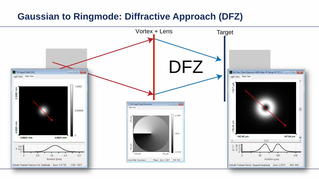
Gaussian to Ringmode Diffractive Approach (DFZ)Vortex + Lens Target
Diffractive light shaping by coherent superposition
Diffractive beam splitter and diffuser
Shaping by ldquoBeam ScanningrdquoTarget
Basic source mode eg Gaussian
Shaping by ldquoBeam Scanningrdquo
bull Beam splits at shaperbull Field behind shaper is in diffractive field zonebull Shaper is grating DOE
Shaper Target
Target pattern is ldquowrittenrdquo by scanned beam in target plane
Illustration of Deflection
Phase of transmission Intensity in target
Illustration of Deflection
Phase of transmission Intensity in target
Illustration of Deflection
Phase of transmission Intensity in target
Illustration of Deflection
Phase of transmission Intensity in target
Illustration of Deflection
Phase of transmission Intensity in target
Illustration of Deflection Sum
Phase of transmission Intensity in target
Basic Design Situations Splitting
bull Spots overlap in target patten diffractive diffuser
bull Spots in target pattern do not overlap diffractive beam splitter
Basic Design Situations Splitting
bull Spots overlap in target patten diffractive diffuser
Spots in target pattern do not bulloverlap diffractive beam splitter
Shaping by ldquoBeam Scanningrdquo
Amplitude Phase
Iterative Fourier Transform Algorithm
Advanced diffractive optics design techniques
Design technique (IFTA) implemented in VirtualLabtrade
Micro-structured surface profile
Fabricated at IAP University of Jena
Feature Sizes of Element
Feature sizeabout 400 nm
4 height levels
Optical Experiment
Jenaacutes sbquoSkylinelsquo
Comments on Diffuser Technology
Very flexible in light pattern generationbullRobust against adjustment problems bullCoherent light leads to speckle patternbullSize of speckle features can be adjusted by focusing systembullDiffusers work for partially coherent beams bullPartially coherent beams smooth the speckle pattern effect can be simulated bullwith VirtualLabtrade
Diffractive Optics Pattern Generation
Diffuser technology
Diffractive Optics Pattern Generation
Diffuser technology Design very chromatic
Source RGB
Solution by Integrated Diffractive Optics
wwwLightTranscom112
Far Field Propagation
Source Plane Wave RGB Transmission Regions
Waveguide Component
High NA Beam Splitter by Two DOElsquos
Parameter Value amp Unitnumber of orders 11 x 11order separation 1 x 1 degperiod 3035 x 3035 micrompixel size 690 x 690 nmdiscrete height levels 8material fused silica
surfaceprofile
paraxial beam splitter
Specification Second Beam Splitter
Parameter Value amp Unitnumber of orders 5 x 5order separation 11 x 11 degperiod 273 x 273 micrompixel size 130 x 130 nmdiscrete height levels 8material fused silica
surfaceprofile
high-NA beam splitter
Results Spot Diagram
spot diagram
combination of both beam splitter generate 55 x 55 order with 55x 55deg full
opening spread
a
Results Output Evaluation with FMM
Light shaping by lateral decomposition
Elementary cell array components
Array of Deflectors
Array of Deflectors
Deflection can be done by gratings prisms mirrors
TaskSystem Illustration
Cell Array Element
spherical wave(point source)
cell array structurebuilt up withbull prismsbull gratingsbull mirrors
Parameter Description Value amp Unittype RGB LEDemitter size 100 x 100 micromwavelength (473 532 635) nmpolarization right circularly polarized lightnumber of lateral modes 3 x 3Total number of lateral andspectral modes
27
Specification Light Source
Specification Cell Array
Parameter Value amp Unitnumber of cells 100 x 100cell size 125 x 125 micromarray aperture 125 x 125 mm
Results 3D System Ray Tracing
Results Grating Cells Array
spot
dia
gram
inte
nsity
pat
tern
(re
al c
olor
vie
w)
for grating cells array strong dispersion
effects occur
Results Prism Cells Array
spot
dia
gram
inte
nsity
pat
tern
(re
al c
olor
vie
w)
the dispersion is significantly reduced by
using prisms
Results Mirror Cells Array
spot
dia
gram
inte
nsity
pat
tern
(re
al c
olor
vie
w)
due to reflective approach no dispersion
effects occur
Light shaping by lateral decomposition
Lens and freeform array components
Array of Micro-optical Components
Lateral combination of elementary light shaping solutions
TaskSystem Illustration
50 mm Angular Spectrum (Far Field)
LED + collimation optic
aperiodic refractive beam shaper array (aBSA)
camera detector
Specs Light Source
spectrum model
fast and accurate modeling of a white bulllight LEDdesign and analysis an aperiodic bullrefractive beam shaper array to optimize a top hat intensity pattern
Highlightshere
Results Intensity Pattern (real color view)
aperiodic beam shaper array periodic microlens array
a
Summary
Introduction of a geometric branch of physical optics bullwith the help of the geometric Fourier transform Refractive and diffractive light shaping concepts bullfollow a unified theory in physical optics Classification of light shaping concepts dependent of bullpositions of shaper(s) and target in field zones Elementary shaping concepts can be combinedbull
Superposition in same area eg beam splitterminusLaterally combined eg cell arrayminus -type components
Further investigations on the basis of the unified bulltheory will reveal further concepts and deeper understanding of light shaping
bull Designs and simulations done with VirtualLab Fusion software
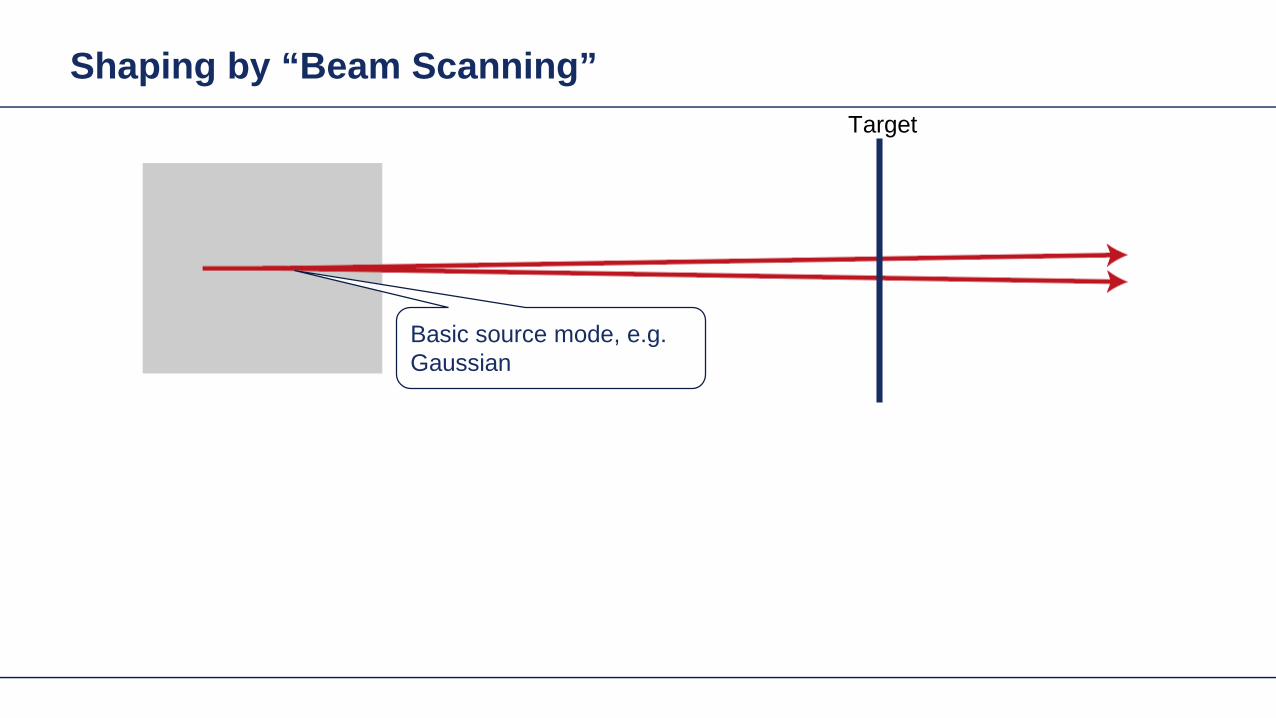
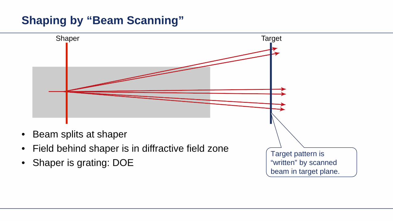
Shaping by ldquoBeam Scanningrdquo
bull Beam splits at shaperbull Field behind shaper is in diffractive field zonebull Shaper is grating DOE
Shaper Target
Target pattern is ldquowrittenrdquo by scanned beam in target plane
Illustration of Deflection
Phase of transmission Intensity in target
Illustration of Deflection
Phase of transmission Intensity in target
Illustration of Deflection
Phase of transmission Intensity in target
Illustration of Deflection
Phase of transmission Intensity in target
Illustration of Deflection
Phase of transmission Intensity in target
Illustration of Deflection Sum
Phase of transmission Intensity in target
Basic Design Situations Splitting
bull Spots overlap in target patten diffractive diffuser
bull Spots in target pattern do not overlap diffractive beam splitter
Basic Design Situations Splitting
bull Spots overlap in target patten diffractive diffuser
Spots in target pattern do not bulloverlap diffractive beam splitter
Shaping by ldquoBeam Scanningrdquo
Amplitude Phase
Iterative Fourier Transform Algorithm
Advanced diffractive optics design techniques
Design technique (IFTA) implemented in VirtualLabtrade
Micro-structured surface profile
Fabricated at IAP University of Jena
Feature Sizes of Element
Feature sizeabout 400 nm
4 height levels
Optical Experiment
Jenaacutes sbquoSkylinelsquo
Comments on Diffuser Technology
Very flexible in light pattern generationbullRobust against adjustment problems bullCoherent light leads to speckle patternbullSize of speckle features can be adjusted by focusing systembullDiffusers work for partially coherent beams bullPartially coherent beams smooth the speckle pattern effect can be simulated bullwith VirtualLabtrade
Diffractive Optics Pattern Generation
Diffuser technology
Diffractive Optics Pattern Generation
Diffuser technology Design very chromatic
Source RGB
Solution by Integrated Diffractive Optics
wwwLightTranscom112
Far Field Propagation
Source Plane Wave RGB Transmission Regions
Waveguide Component
High NA Beam Splitter by Two DOElsquos
Parameter Value amp Unitnumber of orders 11 x 11order separation 1 x 1 degperiod 3035 x 3035 micrompixel size 690 x 690 nmdiscrete height levels 8material fused silica
surfaceprofile
paraxial beam splitter
Specification Second Beam Splitter
Parameter Value amp Unitnumber of orders 5 x 5order separation 11 x 11 degperiod 273 x 273 micrompixel size 130 x 130 nmdiscrete height levels 8material fused silica
surfaceprofile
high-NA beam splitter
Results Spot Diagram
spot diagram
combination of both beam splitter generate 55 x 55 order with 55x 55deg full
opening spread
a
Results Output Evaluation with FMM
Light shaping by lateral decomposition
Elementary cell array components
Array of Deflectors
Array of Deflectors
Deflection can be done by gratings prisms mirrors
TaskSystem Illustration
Cell Array Element
spherical wave(point source)
cell array structurebuilt up withbull prismsbull gratingsbull mirrors
Parameter Description Value amp Unittype RGB LEDemitter size 100 x 100 micromwavelength (473 532 635) nmpolarization right circularly polarized lightnumber of lateral modes 3 x 3Total number of lateral andspectral modes
27
Specification Light Source
Specification Cell Array
Parameter Value amp Unitnumber of cells 100 x 100cell size 125 x 125 micromarray aperture 125 x 125 mm
Results 3D System Ray Tracing
Results Grating Cells Array
spot
dia
gram
inte
nsity
pat
tern
(re
al c
olor
vie
w)
for grating cells array strong dispersion
effects occur
Results Prism Cells Array
spot
dia
gram
inte
nsity
pat
tern
(re
al c
olor
vie
w)
the dispersion is significantly reduced by
using prisms
Results Mirror Cells Array
spot
dia
gram
inte
nsity
pat
tern
(re
al c
olor
vie
w)
due to reflective approach no dispersion
effects occur
Light shaping by lateral decomposition
Lens and freeform array components
Array of Micro-optical Components
Lateral combination of elementary light shaping solutions
TaskSystem Illustration
50 mm Angular Spectrum (Far Field)
LED + collimation optic
aperiodic refractive beam shaper array (aBSA)
camera detector
Specs Light Source
spectrum model
fast and accurate modeling of a white bulllight LEDdesign and analysis an aperiodic bullrefractive beam shaper array to optimize a top hat intensity pattern
Highlightshere
Results Intensity Pattern (real color view)
aperiodic beam shaper array periodic microlens array
a
Summary
Introduction of a geometric branch of physical optics bullwith the help of the geometric Fourier transform Refractive and diffractive light shaping concepts bullfollow a unified theory in physical optics Classification of light shaping concepts dependent of bullpositions of shaper(s) and target in field zones Elementary shaping concepts can be combinedbull
Superposition in same area eg beam splitterminusLaterally combined eg cell arrayminus -type components
Further investigations on the basis of the unified bulltheory will reveal further concepts and deeper understanding of light shaping
bull Designs and simulations done with VirtualLab Fusion software

Illustration of Deflection
Phase of transmission Intensity in target
Illustration of Deflection
Phase of transmission Intensity in target
Illustration of Deflection
Phase of transmission Intensity in target
Illustration of Deflection
Phase of transmission Intensity in target
Illustration of Deflection
Phase of transmission Intensity in target
Illustration of Deflection Sum
Phase of transmission Intensity in target
Basic Design Situations Splitting
bull Spots overlap in target patten diffractive diffuser
bull Spots in target pattern do not overlap diffractive beam splitter
Basic Design Situations Splitting
bull Spots overlap in target patten diffractive diffuser
Spots in target pattern do not bulloverlap diffractive beam splitter
Shaping by ldquoBeam Scanningrdquo
Amplitude Phase
Iterative Fourier Transform Algorithm
Advanced diffractive optics design techniques
Design technique (IFTA) implemented in VirtualLabtrade
Micro-structured surface profile
Fabricated at IAP University of Jena
Feature Sizes of Element
Feature sizeabout 400 nm
4 height levels
Optical Experiment
Jenaacutes sbquoSkylinelsquo
Comments on Diffuser Technology
Very flexible in light pattern generationbullRobust against adjustment problems bullCoherent light leads to speckle patternbullSize of speckle features can be adjusted by focusing systembullDiffusers work for partially coherent beams bullPartially coherent beams smooth the speckle pattern effect can be simulated bullwith VirtualLabtrade
Diffractive Optics Pattern Generation
Diffuser technology
Diffractive Optics Pattern Generation
Diffuser technology Design very chromatic
Source RGB
Solution by Integrated Diffractive Optics
wwwLightTranscom112
Far Field Propagation
Source Plane Wave RGB Transmission Regions
Waveguide Component
High NA Beam Splitter by Two DOElsquos
Parameter Value amp Unitnumber of orders 11 x 11order separation 1 x 1 degperiod 3035 x 3035 micrompixel size 690 x 690 nmdiscrete height levels 8material fused silica
surfaceprofile
paraxial beam splitter
Specification Second Beam Splitter
Parameter Value amp Unitnumber of orders 5 x 5order separation 11 x 11 degperiod 273 x 273 micrompixel size 130 x 130 nmdiscrete height levels 8material fused silica
surfaceprofile
high-NA beam splitter
Results Spot Diagram
spot diagram
combination of both beam splitter generate 55 x 55 order with 55x 55deg full
opening spread
a
Results Output Evaluation with FMM
Light shaping by lateral decomposition
Elementary cell array components
Array of Deflectors
Array of Deflectors
Deflection can be done by gratings prisms mirrors
TaskSystem Illustration
Cell Array Element
spherical wave(point source)
cell array structurebuilt up withbull prismsbull gratingsbull mirrors
Parameter Description Value amp Unittype RGB LEDemitter size 100 x 100 micromwavelength (473 532 635) nmpolarization right circularly polarized lightnumber of lateral modes 3 x 3Total number of lateral andspectral modes
27
Specification Light Source
Specification Cell Array
Parameter Value amp Unitnumber of cells 100 x 100cell size 125 x 125 micromarray aperture 125 x 125 mm
Results 3D System Ray Tracing
Results Grating Cells Array
spot
dia
gram
inte
nsity
pat
tern
(re
al c
olor
vie
w)
for grating cells array strong dispersion
effects occur
Results Prism Cells Array
spot
dia
gram
inte
nsity
pat
tern
(re
al c
olor
vie
w)
the dispersion is significantly reduced by
using prisms
Results Mirror Cells Array
spot
dia
gram
inte
nsity
pat
tern
(re
al c
olor
vie
w)
due to reflective approach no dispersion
effects occur
Light shaping by lateral decomposition
Lens and freeform array components
Array of Micro-optical Components
Lateral combination of elementary light shaping solutions
TaskSystem Illustration
50 mm Angular Spectrum (Far Field)
LED + collimation optic
aperiodic refractive beam shaper array (aBSA)
camera detector
Specs Light Source
spectrum model
fast and accurate modeling of a white bulllight LEDdesign and analysis an aperiodic bullrefractive beam shaper array to optimize a top hat intensity pattern
Highlightshere
Results Intensity Pattern (real color view)
aperiodic beam shaper array periodic microlens array
a
Summary
Introduction of a geometric branch of physical optics bullwith the help of the geometric Fourier transform Refractive and diffractive light shaping concepts bullfollow a unified theory in physical optics Classification of light shaping concepts dependent of bullpositions of shaper(s) and target in field zones Elementary shaping concepts can be combinedbull
Superposition in same area eg beam splitterminusLaterally combined eg cell arrayminus -type components
Further investigations on the basis of the unified bulltheory will reveal further concepts and deeper understanding of light shaping
bull Designs and simulations done with VirtualLab Fusion software

Illustration of Deflection
Phase of transmission Intensity in target
Illustration of Deflection
Phase of transmission Intensity in target
Illustration of Deflection
Phase of transmission Intensity in target
Illustration of Deflection
Phase of transmission Intensity in target
Illustration of Deflection Sum
Phase of transmission Intensity in target
Basic Design Situations Splitting
bull Spots overlap in target patten diffractive diffuser
bull Spots in target pattern do not overlap diffractive beam splitter
Basic Design Situations Splitting
bull Spots overlap in target patten diffractive diffuser
Spots in target pattern do not bulloverlap diffractive beam splitter
Shaping by ldquoBeam Scanningrdquo
Amplitude Phase
Iterative Fourier Transform Algorithm
Advanced diffractive optics design techniques
Design technique (IFTA) implemented in VirtualLabtrade
Micro-structured surface profile
Fabricated at IAP University of Jena
Feature Sizes of Element
Feature sizeabout 400 nm
4 height levels
Optical Experiment
Jenaacutes sbquoSkylinelsquo
Comments on Diffuser Technology
Very flexible in light pattern generationbullRobust against adjustment problems bullCoherent light leads to speckle patternbullSize of speckle features can be adjusted by focusing systembullDiffusers work for partially coherent beams bullPartially coherent beams smooth the speckle pattern effect can be simulated bullwith VirtualLabtrade
Diffractive Optics Pattern Generation
Diffuser technology
Diffractive Optics Pattern Generation
Diffuser technology Design very chromatic
Source RGB
Solution by Integrated Diffractive Optics
wwwLightTranscom112
Far Field Propagation
Source Plane Wave RGB Transmission Regions
Waveguide Component
High NA Beam Splitter by Two DOElsquos
Parameter Value amp Unitnumber of orders 11 x 11order separation 1 x 1 degperiod 3035 x 3035 micrompixel size 690 x 690 nmdiscrete height levels 8material fused silica
surfaceprofile
paraxial beam splitter
Specification Second Beam Splitter
Parameter Value amp Unitnumber of orders 5 x 5order separation 11 x 11 degperiod 273 x 273 micrompixel size 130 x 130 nmdiscrete height levels 8material fused silica
surfaceprofile
high-NA beam splitter
Results Spot Diagram
spot diagram
combination of both beam splitter generate 55 x 55 order with 55x 55deg full
opening spread
a
Results Output Evaluation with FMM
Light shaping by lateral decomposition
Elementary cell array components
Array of Deflectors
Array of Deflectors
Deflection can be done by gratings prisms mirrors
TaskSystem Illustration
Cell Array Element
spherical wave(point source)
cell array structurebuilt up withbull prismsbull gratingsbull mirrors
Parameter Description Value amp Unittype RGB LEDemitter size 100 x 100 micromwavelength (473 532 635) nmpolarization right circularly polarized lightnumber of lateral modes 3 x 3Total number of lateral andspectral modes
27
Specification Light Source
Specification Cell Array
Parameter Value amp Unitnumber of cells 100 x 100cell size 125 x 125 micromarray aperture 125 x 125 mm
Results 3D System Ray Tracing
Results Grating Cells Array
spot
dia
gram
inte
nsity
pat
tern
(re
al c
olor
vie
w)
for grating cells array strong dispersion
effects occur
Results Prism Cells Array
spot
dia
gram
inte
nsity
pat
tern
(re
al c
olor
vie
w)
the dispersion is significantly reduced by
using prisms
Results Mirror Cells Array
spot
dia
gram
inte
nsity
pat
tern
(re
al c
olor
vie
w)
due to reflective approach no dispersion
effects occur
Light shaping by lateral decomposition
Lens and freeform array components
Array of Micro-optical Components
Lateral combination of elementary light shaping solutions
TaskSystem Illustration
50 mm Angular Spectrum (Far Field)
LED + collimation optic
aperiodic refractive beam shaper array (aBSA)
camera detector
Specs Light Source
spectrum model
fast and accurate modeling of a white bulllight LEDdesign and analysis an aperiodic bullrefractive beam shaper array to optimize a top hat intensity pattern
Highlightshere
Results Intensity Pattern (real color view)
aperiodic beam shaper array periodic microlens array
a
Summary
Introduction of a geometric branch of physical optics bullwith the help of the geometric Fourier transform Refractive and diffractive light shaping concepts bullfollow a unified theory in physical optics Classification of light shaping concepts dependent of bullpositions of shaper(s) and target in field zones Elementary shaping concepts can be combinedbull
Superposition in same area eg beam splitterminusLaterally combined eg cell arrayminus -type components
Further investigations on the basis of the unified bulltheory will reveal further concepts and deeper understanding of light shaping
bull Designs and simulations done with VirtualLab Fusion software
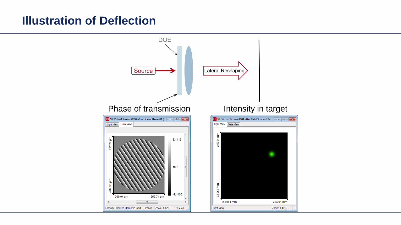
Illustration of Deflection
Phase of transmission Intensity in target
Illustration of Deflection
Phase of transmission Intensity in target
Illustration of Deflection
Phase of transmission Intensity in target
Illustration of Deflection Sum
Phase of transmission Intensity in target
Basic Design Situations Splitting
bull Spots overlap in target patten diffractive diffuser
bull Spots in target pattern do not overlap diffractive beam splitter
Basic Design Situations Splitting
bull Spots overlap in target patten diffractive diffuser
Spots in target pattern do not bulloverlap diffractive beam splitter
Shaping by ldquoBeam Scanningrdquo
Amplitude Phase
Iterative Fourier Transform Algorithm
Advanced diffractive optics design techniques
Design technique (IFTA) implemented in VirtualLabtrade
Micro-structured surface profile
Fabricated at IAP University of Jena
Feature Sizes of Element
Feature sizeabout 400 nm
4 height levels
Optical Experiment
Jenaacutes sbquoSkylinelsquo
Comments on Diffuser Technology
Very flexible in light pattern generationbullRobust against adjustment problems bullCoherent light leads to speckle patternbullSize of speckle features can be adjusted by focusing systembullDiffusers work for partially coherent beams bullPartially coherent beams smooth the speckle pattern effect can be simulated bullwith VirtualLabtrade
Diffractive Optics Pattern Generation
Diffuser technology
Diffractive Optics Pattern Generation
Diffuser technology Design very chromatic
Source RGB
Solution by Integrated Diffractive Optics
wwwLightTranscom112
Far Field Propagation
Source Plane Wave RGB Transmission Regions
Waveguide Component
High NA Beam Splitter by Two DOElsquos
Parameter Value amp Unitnumber of orders 11 x 11order separation 1 x 1 degperiod 3035 x 3035 micrompixel size 690 x 690 nmdiscrete height levels 8material fused silica
surfaceprofile
paraxial beam splitter
Specification Second Beam Splitter
Parameter Value amp Unitnumber of orders 5 x 5order separation 11 x 11 degperiod 273 x 273 micrompixel size 130 x 130 nmdiscrete height levels 8material fused silica
surfaceprofile
high-NA beam splitter
Results Spot Diagram
spot diagram
combination of both beam splitter generate 55 x 55 order with 55x 55deg full
opening spread
a
Results Output Evaluation with FMM
Light shaping by lateral decomposition
Elementary cell array components
Array of Deflectors
Array of Deflectors
Deflection can be done by gratings prisms mirrors
TaskSystem Illustration
Cell Array Element
spherical wave(point source)
cell array structurebuilt up withbull prismsbull gratingsbull mirrors
Parameter Description Value amp Unittype RGB LEDemitter size 100 x 100 micromwavelength (473 532 635) nmpolarization right circularly polarized lightnumber of lateral modes 3 x 3Total number of lateral andspectral modes
27
Specification Light Source
Specification Cell Array
Parameter Value amp Unitnumber of cells 100 x 100cell size 125 x 125 micromarray aperture 125 x 125 mm
Results 3D System Ray Tracing
Results Grating Cells Array
spot
dia
gram
inte
nsity
pat
tern
(re
al c
olor
vie
w)
for grating cells array strong dispersion
effects occur
Results Prism Cells Array
spot
dia
gram
inte
nsity
pat
tern
(re
al c
olor
vie
w)
the dispersion is significantly reduced by
using prisms
Results Mirror Cells Array
spot
dia
gram
inte
nsity
pat
tern
(re
al c
olor
vie
w)
due to reflective approach no dispersion
effects occur
Light shaping by lateral decomposition
Lens and freeform array components
Array of Micro-optical Components
Lateral combination of elementary light shaping solutions
TaskSystem Illustration
50 mm Angular Spectrum (Far Field)
LED + collimation optic
aperiodic refractive beam shaper array (aBSA)
camera detector
Specs Light Source
spectrum model
fast and accurate modeling of a white bulllight LEDdesign and analysis an aperiodic bullrefractive beam shaper array to optimize a top hat intensity pattern
Highlightshere
Results Intensity Pattern (real color view)
aperiodic beam shaper array periodic microlens array
a
Summary
Introduction of a geometric branch of physical optics bullwith the help of the geometric Fourier transform Refractive and diffractive light shaping concepts bullfollow a unified theory in physical optics Classification of light shaping concepts dependent of bullpositions of shaper(s) and target in field zones Elementary shaping concepts can be combinedbull
Superposition in same area eg beam splitterminusLaterally combined eg cell arrayminus -type components
Further investigations on the basis of the unified bulltheory will reveal further concepts and deeper understanding of light shaping
bull Designs and simulations done with VirtualLab Fusion software

Illustration of Deflection
Phase of transmission Intensity in target
Illustration of Deflection
Phase of transmission Intensity in target
Illustration of Deflection Sum
Phase of transmission Intensity in target
Basic Design Situations Splitting
bull Spots overlap in target patten diffractive diffuser
bull Spots in target pattern do not overlap diffractive beam splitter
Basic Design Situations Splitting
bull Spots overlap in target patten diffractive diffuser
Spots in target pattern do not bulloverlap diffractive beam splitter
Shaping by ldquoBeam Scanningrdquo
Amplitude Phase
Iterative Fourier Transform Algorithm
Advanced diffractive optics design techniques
Design technique (IFTA) implemented in VirtualLabtrade
Micro-structured surface profile
Fabricated at IAP University of Jena
Feature Sizes of Element
Feature sizeabout 400 nm
4 height levels
Optical Experiment
Jenaacutes sbquoSkylinelsquo
Comments on Diffuser Technology
Very flexible in light pattern generationbullRobust against adjustment problems bullCoherent light leads to speckle patternbullSize of speckle features can be adjusted by focusing systembullDiffusers work for partially coherent beams bullPartially coherent beams smooth the speckle pattern effect can be simulated bullwith VirtualLabtrade
Diffractive Optics Pattern Generation
Diffuser technology
Diffractive Optics Pattern Generation
Diffuser technology Design very chromatic
Source RGB
Solution by Integrated Diffractive Optics
wwwLightTranscom112
Far Field Propagation
Source Plane Wave RGB Transmission Regions
Waveguide Component
High NA Beam Splitter by Two DOElsquos
Parameter Value amp Unitnumber of orders 11 x 11order separation 1 x 1 degperiod 3035 x 3035 micrompixel size 690 x 690 nmdiscrete height levels 8material fused silica
surfaceprofile
paraxial beam splitter
Specification Second Beam Splitter
Parameter Value amp Unitnumber of orders 5 x 5order separation 11 x 11 degperiod 273 x 273 micrompixel size 130 x 130 nmdiscrete height levels 8material fused silica
surfaceprofile
high-NA beam splitter
Results Spot Diagram
spot diagram
combination of both beam splitter generate 55 x 55 order with 55x 55deg full
opening spread
a
Results Output Evaluation with FMM
Light shaping by lateral decomposition
Elementary cell array components
Array of Deflectors
Array of Deflectors
Deflection can be done by gratings prisms mirrors
TaskSystem Illustration
Cell Array Element
spherical wave(point source)
cell array structurebuilt up withbull prismsbull gratingsbull mirrors
Parameter Description Value amp Unittype RGB LEDemitter size 100 x 100 micromwavelength (473 532 635) nmpolarization right circularly polarized lightnumber of lateral modes 3 x 3Total number of lateral andspectral modes
27
Specification Light Source
Specification Cell Array
Parameter Value amp Unitnumber of cells 100 x 100cell size 125 x 125 micromarray aperture 125 x 125 mm
Results 3D System Ray Tracing
Results Grating Cells Array
spot
dia
gram
inte
nsity
pat
tern
(re
al c
olor
vie
w)
for grating cells array strong dispersion
effects occur
Results Prism Cells Array
spot
dia
gram
inte
nsity
pat
tern
(re
al c
olor
vie
w)
the dispersion is significantly reduced by
using prisms
Results Mirror Cells Array
spot
dia
gram
inte
nsity
pat
tern
(re
al c
olor
vie
w)
due to reflective approach no dispersion
effects occur
Light shaping by lateral decomposition
Lens and freeform array components
Array of Micro-optical Components
Lateral combination of elementary light shaping solutions
TaskSystem Illustration
50 mm Angular Spectrum (Far Field)
LED + collimation optic
aperiodic refractive beam shaper array (aBSA)
camera detector
Specs Light Source
spectrum model
fast and accurate modeling of a white bulllight LEDdesign and analysis an aperiodic bullrefractive beam shaper array to optimize a top hat intensity pattern
Highlightshere
Results Intensity Pattern (real color view)
aperiodic beam shaper array periodic microlens array
a
Summary
Introduction of a geometric branch of physical optics bullwith the help of the geometric Fourier transform Refractive and diffractive light shaping concepts bullfollow a unified theory in physical optics Classification of light shaping concepts dependent of bullpositions of shaper(s) and target in field zones Elementary shaping concepts can be combinedbull
Superposition in same area eg beam splitterminusLaterally combined eg cell arrayminus -type components
Further investigations on the basis of the unified bulltheory will reveal further concepts and deeper understanding of light shaping
bull Designs and simulations done with VirtualLab Fusion software

Illustration of Deflection
Phase of transmission Intensity in target
Illustration of Deflection Sum
Phase of transmission Intensity in target
Basic Design Situations Splitting
bull Spots overlap in target patten diffractive diffuser
bull Spots in target pattern do not overlap diffractive beam splitter
Basic Design Situations Splitting
bull Spots overlap in target patten diffractive diffuser
Spots in target pattern do not bulloverlap diffractive beam splitter
Shaping by ldquoBeam Scanningrdquo
Amplitude Phase
Iterative Fourier Transform Algorithm
Advanced diffractive optics design techniques
Design technique (IFTA) implemented in VirtualLabtrade
Micro-structured surface profile
Fabricated at IAP University of Jena
Feature Sizes of Element
Feature sizeabout 400 nm
4 height levels
Optical Experiment
Jenaacutes sbquoSkylinelsquo
Comments on Diffuser Technology
Very flexible in light pattern generationbullRobust against adjustment problems bullCoherent light leads to speckle patternbullSize of speckle features can be adjusted by focusing systembullDiffusers work for partially coherent beams bullPartially coherent beams smooth the speckle pattern effect can be simulated bullwith VirtualLabtrade
Diffractive Optics Pattern Generation
Diffuser technology
Diffractive Optics Pattern Generation
Diffuser technology Design very chromatic
Source RGB
Solution by Integrated Diffractive Optics
wwwLightTranscom112
Far Field Propagation
Source Plane Wave RGB Transmission Regions
Waveguide Component
High NA Beam Splitter by Two DOElsquos
Parameter Value amp Unitnumber of orders 11 x 11order separation 1 x 1 degperiod 3035 x 3035 micrompixel size 690 x 690 nmdiscrete height levels 8material fused silica
surfaceprofile
paraxial beam splitter
Specification Second Beam Splitter
Parameter Value amp Unitnumber of orders 5 x 5order separation 11 x 11 degperiod 273 x 273 micrompixel size 130 x 130 nmdiscrete height levels 8material fused silica
surfaceprofile
high-NA beam splitter
Results Spot Diagram
spot diagram
combination of both beam splitter generate 55 x 55 order with 55x 55deg full
opening spread
a
Results Output Evaluation with FMM
Light shaping by lateral decomposition
Elementary cell array components
Array of Deflectors
Array of Deflectors
Deflection can be done by gratings prisms mirrors
TaskSystem Illustration
Cell Array Element
spherical wave(point source)
cell array structurebuilt up withbull prismsbull gratingsbull mirrors
Parameter Description Value amp Unittype RGB LEDemitter size 100 x 100 micromwavelength (473 532 635) nmpolarization right circularly polarized lightnumber of lateral modes 3 x 3Total number of lateral andspectral modes
27
Specification Light Source
Specification Cell Array
Parameter Value amp Unitnumber of cells 100 x 100cell size 125 x 125 micromarray aperture 125 x 125 mm
Results 3D System Ray Tracing
Results Grating Cells Array
spot
dia
gram
inte
nsity
pat
tern
(re
al c
olor
vie
w)
for grating cells array strong dispersion
effects occur
Results Prism Cells Array
spot
dia
gram
inte
nsity
pat
tern
(re
al c
olor
vie
w)
the dispersion is significantly reduced by
using prisms
Results Mirror Cells Array
spot
dia
gram
inte
nsity
pat
tern
(re
al c
olor
vie
w)
due to reflective approach no dispersion
effects occur
Light shaping by lateral decomposition
Lens and freeform array components
Array of Micro-optical Components
Lateral combination of elementary light shaping solutions
TaskSystem Illustration
50 mm Angular Spectrum (Far Field)
LED + collimation optic
aperiodic refractive beam shaper array (aBSA)
camera detector
Specs Light Source
spectrum model
fast and accurate modeling of a white bulllight LEDdesign and analysis an aperiodic bullrefractive beam shaper array to optimize a top hat intensity pattern
Highlightshere
Results Intensity Pattern (real color view)
aperiodic beam shaper array periodic microlens array
a
Summary
Introduction of a geometric branch of physical optics bullwith the help of the geometric Fourier transform Refractive and diffractive light shaping concepts bullfollow a unified theory in physical optics Classification of light shaping concepts dependent of bullpositions of shaper(s) and target in field zones Elementary shaping concepts can be combinedbull
Superposition in same area eg beam splitterminusLaterally combined eg cell arrayminus -type components
Further investigations on the basis of the unified bulltheory will reveal further concepts and deeper understanding of light shaping
bull Designs and simulations done with VirtualLab Fusion software
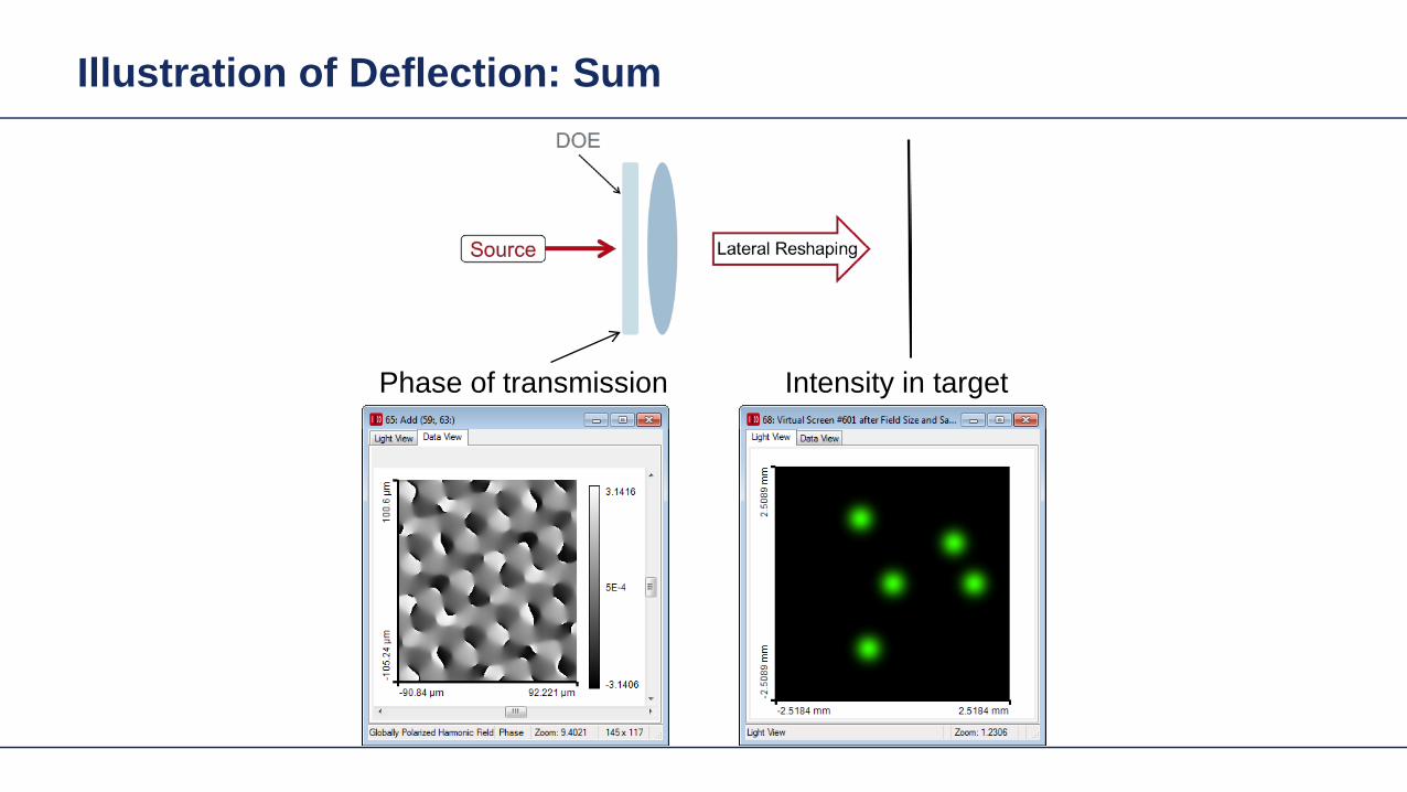

Basic Design Situations Splitting
bull Spots overlap in target patten diffractive diffuser
Spots in target pattern do not bulloverlap diffractive beam splitter
Shaping by ldquoBeam Scanningrdquo
Amplitude Phase
Iterative Fourier Transform Algorithm
Advanced diffractive optics design techniques
Design technique (IFTA) implemented in VirtualLabtrade
Micro-structured surface profile
Fabricated at IAP University of Jena
Feature Sizes of Element
Feature sizeabout 400 nm
4 height levels
Optical Experiment
Jenaacutes sbquoSkylinelsquo
Comments on Diffuser Technology
Very flexible in light pattern generationbullRobust against adjustment problems bullCoherent light leads to speckle patternbullSize of speckle features can be adjusted by focusing systembullDiffusers work for partially coherent beams bullPartially coherent beams smooth the speckle pattern effect can be simulated bullwith VirtualLabtrade
Diffractive Optics Pattern Generation
Diffuser technology
Diffractive Optics Pattern Generation
Diffuser technology Design very chromatic
Source RGB
Solution by Integrated Diffractive Optics
wwwLightTranscom112
Far Field Propagation
Source Plane Wave RGB Transmission Regions
Waveguide Component
High NA Beam Splitter by Two DOElsquos
Parameter Value amp Unitnumber of orders 11 x 11order separation 1 x 1 degperiod 3035 x 3035 micrompixel size 690 x 690 nmdiscrete height levels 8material fused silica
surfaceprofile
paraxial beam splitter
Specification Second Beam Splitter
Parameter Value amp Unitnumber of orders 5 x 5order separation 11 x 11 degperiod 273 x 273 micrompixel size 130 x 130 nmdiscrete height levels 8material fused silica
surfaceprofile
high-NA beam splitter
Results Spot Diagram
spot diagram
combination of both beam splitter generate 55 x 55 order with 55x 55deg full
opening spread
a
Results Output Evaluation with FMM
Light shaping by lateral decomposition
Elementary cell array components
Array of Deflectors
Array of Deflectors
Deflection can be done by gratings prisms mirrors
TaskSystem Illustration
Cell Array Element
spherical wave(point source)
cell array structurebuilt up withbull prismsbull gratingsbull mirrors
Parameter Description Value amp Unittype RGB LEDemitter size 100 x 100 micromwavelength (473 532 635) nmpolarization right circularly polarized lightnumber of lateral modes 3 x 3Total number of lateral andspectral modes
27
Specification Light Source
Specification Cell Array
Parameter Value amp Unitnumber of cells 100 x 100cell size 125 x 125 micromarray aperture 125 x 125 mm
Results 3D System Ray Tracing
Results Grating Cells Array
spot
dia
gram
inte
nsity
pat
tern
(re
al c
olor
vie
w)
for grating cells array strong dispersion
effects occur
Results Prism Cells Array
spot
dia
gram
inte
nsity
pat
tern
(re
al c
olor
vie
w)
the dispersion is significantly reduced by
using prisms
Results Mirror Cells Array
spot
dia
gram
inte
nsity
pat
tern
(re
al c
olor
vie
w)
due to reflective approach no dispersion
effects occur
Light shaping by lateral decomposition
Lens and freeform array components
Array of Micro-optical Components
Lateral combination of elementary light shaping solutions
TaskSystem Illustration
50 mm Angular Spectrum (Far Field)
LED + collimation optic
aperiodic refractive beam shaper array (aBSA)
camera detector
Specs Light Source
spectrum model
fast and accurate modeling of a white bulllight LEDdesign and analysis an aperiodic bullrefractive beam shaper array to optimize a top hat intensity pattern
Highlightshere
Results Intensity Pattern (real color view)
aperiodic beam shaper array periodic microlens array
a
Summary
Introduction of a geometric branch of physical optics bullwith the help of the geometric Fourier transform Refractive and diffractive light shaping concepts bullfollow a unified theory in physical optics Classification of light shaping concepts dependent of bullpositions of shaper(s) and target in field zones Elementary shaping concepts can be combinedbull
Superposition in same area eg beam splitterminusLaterally combined eg cell arrayminus -type components
Further investigations on the basis of the unified bulltheory will reveal further concepts and deeper understanding of light shaping
bull Designs and simulations done with VirtualLab Fusion software
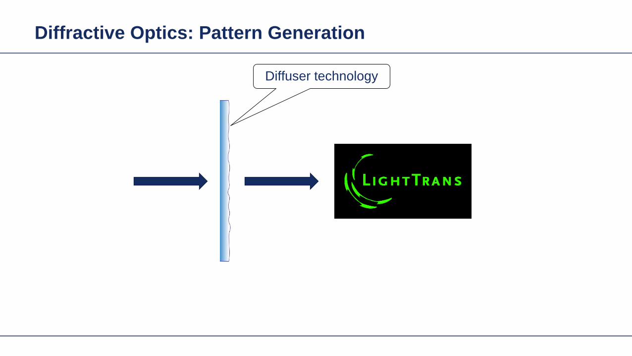
Diffractive Optics Pattern Generation
Diffuser technology Design very chromatic
Source RGB
Solution by Integrated Diffractive Optics
wwwLightTranscom112
Far Field Propagation
Source Plane Wave RGB Transmission Regions
Waveguide Component
High NA Beam Splitter by Two DOElsquos
Parameter Value amp Unitnumber of orders 11 x 11order separation 1 x 1 degperiod 3035 x 3035 micrompixel size 690 x 690 nmdiscrete height levels 8material fused silica
surfaceprofile
paraxial beam splitter
Specification Second Beam Splitter
Parameter Value amp Unitnumber of orders 5 x 5order separation 11 x 11 degperiod 273 x 273 micrompixel size 130 x 130 nmdiscrete height levels 8material fused silica
surfaceprofile
high-NA beam splitter
Results Spot Diagram
spot diagram
combination of both beam splitter generate 55 x 55 order with 55x 55deg full
opening spread
a
Results Output Evaluation with FMM
Light shaping by lateral decomposition
Elementary cell array components
Array of Deflectors
Array of Deflectors
Deflection can be done by gratings prisms mirrors
TaskSystem Illustration
Cell Array Element
spherical wave(point source)
cell array structurebuilt up withbull prismsbull gratingsbull mirrors
Parameter Description Value amp Unittype RGB LEDemitter size 100 x 100 micromwavelength (473 532 635) nmpolarization right circularly polarized lightnumber of lateral modes 3 x 3Total number of lateral andspectral modes
27
Specification Light Source
Specification Cell Array
Parameter Value amp Unitnumber of cells 100 x 100cell size 125 x 125 micromarray aperture 125 x 125 mm
Results 3D System Ray Tracing
Results Grating Cells Array
spot
dia
gram
inte
nsity
pat
tern
(re
al c
olor
vie
w)
for grating cells array strong dispersion
effects occur
Results Prism Cells Array
spot
dia
gram
inte
nsity
pat
tern
(re
al c
olor
vie
w)
the dispersion is significantly reduced by
using prisms
Results Mirror Cells Array
spot
dia
gram
inte
nsity
pat
tern
(re
al c
olor
vie
w)
due to reflective approach no dispersion
effects occur
Light shaping by lateral decomposition
Lens and freeform array components
Array of Micro-optical Components
Lateral combination of elementary light shaping solutions
TaskSystem Illustration
50 mm Angular Spectrum (Far Field)
LED + collimation optic
aperiodic refractive beam shaper array (aBSA)
camera detector
Specs Light Source
spectrum model
fast and accurate modeling of a white bulllight LEDdesign and analysis an aperiodic bullrefractive beam shaper array to optimize a top hat intensity pattern
Highlightshere
Results Intensity Pattern (real color view)
aperiodic beam shaper array periodic microlens array
a
Summary
Introduction of a geometric branch of physical optics bullwith the help of the geometric Fourier transform Refractive and diffractive light shaping concepts bullfollow a unified theory in physical optics Classification of light shaping concepts dependent of bullpositions of shaper(s) and target in field zones Elementary shaping concepts can be combinedbull
Superposition in same area eg beam splitterminusLaterally combined eg cell arrayminus -type components
Further investigations on the basis of the unified bulltheory will reveal further concepts and deeper understanding of light shaping
bull Designs and simulations done with VirtualLab Fusion software

Light shaping by lateral decomposition
Elementary cell array components
Array of Deflectors
Array of Deflectors
Deflection can be done by gratings prisms mirrors
TaskSystem Illustration
Cell Array Element
spherical wave(point source)
cell array structurebuilt up withbull prismsbull gratingsbull mirrors
Parameter Description Value amp Unittype RGB LEDemitter size 100 x 100 micromwavelength (473 532 635) nmpolarization right circularly polarized lightnumber of lateral modes 3 x 3Total number of lateral andspectral modes
27
Specification Light Source
Specification Cell Array
Parameter Value amp Unitnumber of cells 100 x 100cell size 125 x 125 micromarray aperture 125 x 125 mm
Results 3D System Ray Tracing
Results Grating Cells Array
spot
dia
gram
inte
nsity
pat
tern
(re
al c
olor
vie
w)
for grating cells array strong dispersion
effects occur
Results Prism Cells Array
spot
dia
gram
inte
nsity
pat
tern
(re
al c
olor
vie
w)
the dispersion is significantly reduced by
using prisms
Results Mirror Cells Array
spot
dia
gram
inte
nsity
pat
tern
(re
al c
olor
vie
w)
due to reflective approach no dispersion
effects occur
Light shaping by lateral decomposition
Lens and freeform array components
Array of Micro-optical Components
Lateral combination of elementary light shaping solutions
TaskSystem Illustration
50 mm Angular Spectrum (Far Field)
LED + collimation optic
aperiodic refractive beam shaper array (aBSA)
camera detector
Specs Light Source
spectrum model
fast and accurate modeling of a white bulllight LEDdesign and analysis an aperiodic bullrefractive beam shaper array to optimize a top hat intensity pattern
Highlightshere
Results Intensity Pattern (real color view)
aperiodic beam shaper array periodic microlens array
a
Summary
Introduction of a geometric branch of physical optics bullwith the help of the geometric Fourier transform Refractive and diffractive light shaping concepts bullfollow a unified theory in physical optics Classification of light shaping concepts dependent of bullpositions of shaper(s) and target in field zones Elementary shaping concepts can be combinedbull
Superposition in same area eg beam splitterminusLaterally combined eg cell arrayminus -type components
Further investigations on the basis of the unified bulltheory will reveal further concepts and deeper understanding of light shaping
bull Designs and simulations done with VirtualLab Fusion software

Array of Deflectors
Array of Deflectors
Deflection can be done by gratings prisms mirrors
TaskSystem Illustration
Cell Array Element
spherical wave(point source)
cell array structurebuilt up withbull prismsbull gratingsbull mirrors
Parameter Description Value amp Unittype RGB LEDemitter size 100 x 100 micromwavelength (473 532 635) nmpolarization right circularly polarized lightnumber of lateral modes 3 x 3Total number of lateral andspectral modes
27
Specification Light Source
Specification Cell Array
Parameter Value amp Unitnumber of cells 100 x 100cell size 125 x 125 micromarray aperture 125 x 125 mm
Results 3D System Ray Tracing
Results Grating Cells Array
spot
dia
gram
inte
nsity
pat
tern
(re
al c
olor
vie
w)
for grating cells array strong dispersion
effects occur
Results Prism Cells Array
spot
dia
gram
inte
nsity
pat
tern
(re
al c
olor
vie
w)
the dispersion is significantly reduced by
using prisms
Results Mirror Cells Array
spot
dia
gram
inte
nsity
pat
tern
(re
al c
olor
vie
w)
due to reflective approach no dispersion
effects occur
Light shaping by lateral decomposition
Lens and freeform array components
Array of Micro-optical Components
Lateral combination of elementary light shaping solutions
TaskSystem Illustration
50 mm Angular Spectrum (Far Field)
LED + collimation optic
aperiodic refractive beam shaper array (aBSA)
camera detector
Specs Light Source
spectrum model
fast and accurate modeling of a white bulllight LEDdesign and analysis an aperiodic bullrefractive beam shaper array to optimize a top hat intensity pattern
Highlightshere
Results Intensity Pattern (real color view)
aperiodic beam shaper array periodic microlens array
a
Summary
Introduction of a geometric branch of physical optics bullwith the help of the geometric Fourier transform Refractive and diffractive light shaping concepts bullfollow a unified theory in physical optics Classification of light shaping concepts dependent of bullpositions of shaper(s) and target in field zones Elementary shaping concepts can be combinedbull
Superposition in same area eg beam splitterminusLaterally combined eg cell arrayminus -type components
Further investigations on the basis of the unified bulltheory will reveal further concepts and deeper understanding of light shaping
bull Designs and simulations done with VirtualLab Fusion software

Array of Deflectors
Deflection can be done by gratings prisms mirrors
TaskSystem Illustration
Cell Array Element
spherical wave(point source)
cell array structurebuilt up withbull prismsbull gratingsbull mirrors
Parameter Description Value amp Unittype RGB LEDemitter size 100 x 100 micromwavelength (473 532 635) nmpolarization right circularly polarized lightnumber of lateral modes 3 x 3Total number of lateral andspectral modes
27
Specification Light Source
Specification Cell Array
Parameter Value amp Unitnumber of cells 100 x 100cell size 125 x 125 micromarray aperture 125 x 125 mm
Results 3D System Ray Tracing
Results Grating Cells Array
spot
dia
gram
inte
nsity
pat
tern
(re
al c
olor
vie
w)
for grating cells array strong dispersion
effects occur
Results Prism Cells Array
spot
dia
gram
inte
nsity
pat
tern
(re
al c
olor
vie
w)
the dispersion is significantly reduced by
using prisms
Results Mirror Cells Array
spot
dia
gram
inte
nsity
pat
tern
(re
al c
olor
vie
w)
due to reflective approach no dispersion
effects occur
Light shaping by lateral decomposition
Lens and freeform array components
Array of Micro-optical Components
Lateral combination of elementary light shaping solutions
TaskSystem Illustration
50 mm Angular Spectrum (Far Field)
LED + collimation optic
aperiodic refractive beam shaper array (aBSA)
camera detector
Specs Light Source
spectrum model
fast and accurate modeling of a white bulllight LEDdesign and analysis an aperiodic bullrefractive beam shaper array to optimize a top hat intensity pattern
Highlightshere
Results Intensity Pattern (real color view)
aperiodic beam shaper array periodic microlens array
a
Summary
Introduction of a geometric branch of physical optics bullwith the help of the geometric Fourier transform Refractive and diffractive light shaping concepts bullfollow a unified theory in physical optics Classification of light shaping concepts dependent of bullpositions of shaper(s) and target in field zones Elementary shaping concepts can be combinedbull
Superposition in same area eg beam splitterminusLaterally combined eg cell arrayminus -type components
Further investigations on the basis of the unified bulltheory will reveal further concepts and deeper understanding of light shaping
bull Designs and simulations done with VirtualLab Fusion software

TaskSystem Illustration
Cell Array Element
spherical wave(point source)
cell array structurebuilt up withbull prismsbull gratingsbull mirrors
Parameter Description Value amp Unittype RGB LEDemitter size 100 x 100 micromwavelength (473 532 635) nmpolarization right circularly polarized lightnumber of lateral modes 3 x 3Total number of lateral andspectral modes
27
Specification Light Source
Specification Cell Array
Parameter Value amp Unitnumber of cells 100 x 100cell size 125 x 125 micromarray aperture 125 x 125 mm
Results 3D System Ray Tracing
Results Grating Cells Array
spot
dia
gram
inte
nsity
pat
tern
(re
al c
olor
vie
w)
for grating cells array strong dispersion
effects occur
Results Prism Cells Array
spot
dia
gram
inte
nsity
pat
tern
(re
al c
olor
vie
w)
the dispersion is significantly reduced by
using prisms
Results Mirror Cells Array
spot
dia
gram
inte
nsity
pat
tern
(re
al c
olor
vie
w)
due to reflective approach no dispersion
effects occur
Light shaping by lateral decomposition
Lens and freeform array components
Array of Micro-optical Components
Lateral combination of elementary light shaping solutions
TaskSystem Illustration
50 mm Angular Spectrum (Far Field)
LED + collimation optic
aperiodic refractive beam shaper array (aBSA)
camera detector
Specs Light Source
spectrum model
fast and accurate modeling of a white bulllight LEDdesign and analysis an aperiodic bullrefractive beam shaper array to optimize a top hat intensity pattern
Highlightshere
Results Intensity Pattern (real color view)
aperiodic beam shaper array periodic microlens array
a
Summary
Introduction of a geometric branch of physical optics bullwith the help of the geometric Fourier transform Refractive and diffractive light shaping concepts bullfollow a unified theory in physical optics Classification of light shaping concepts dependent of bullpositions of shaper(s) and target in field zones Elementary shaping concepts can be combinedbull
Superposition in same area eg beam splitterminusLaterally combined eg cell arrayminus -type components
Further investigations on the basis of the unified bulltheory will reveal further concepts and deeper understanding of light shaping
bull Designs and simulations done with VirtualLab Fusion software
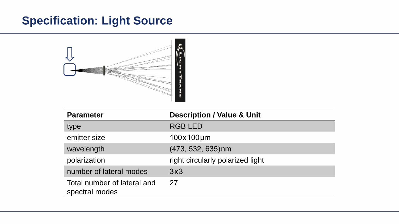
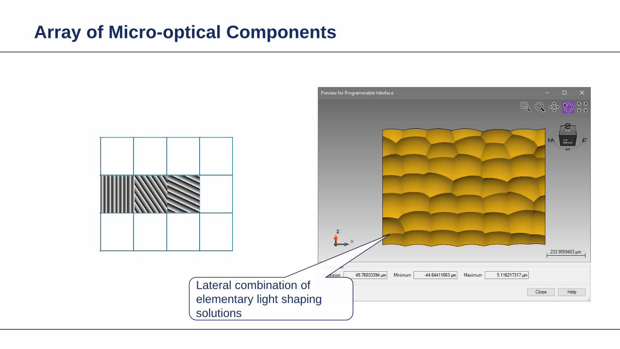
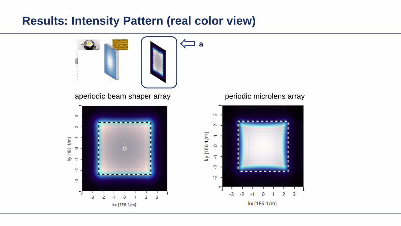