Embed Size (px)
Citation preview
A PHOTOGRAMMETRIC PIPELINE FOR THE 3D RECONSTRUCTION OF CASSIS
IMAGES ON BOARD EXOMARS TGO
E. Simioni a, *, C. Re b, T. Mudric b, A. Pommerol c, N. Thomas c, G. Cremonese b
a CNR-Institute for Photonics and Nanotechnologies, Padova LUXOR, Padova, Italy - [email protected] b INAF-Astronomical Observatory Padova, Padova, Italy (cristina.re, teo.mudric, gabriel.cremonese)@oapd.inaf.it
c University of Bern, Physikalisches Institut, Space Research and Planetology Division, Bern,
Switzerland (antoine.pommerol, nicolas.thomas)@space.unibe.ch
Commission VI, WG VI/4
KEY WORDS: Image Processing, Satellite Images, Software, Digital Photogrammetry
ABSTRACT:
CaSSIS (Colour and Stereo Surface Imaging System) is the stereo imaging system onboard the European Space Agency and
ROSCOSMOS ExoMars Trace Gas Orbiter (TGO) that has been launched on 14 March 2016 and entered a Mars elliptical orbit on 19
October 2016. During the first bounded orbits, CaSSIS returned its first multiband images taken on 22 and 26 November 2016. The
telescope acquired 11 images, each composed by 30 framelets, of the Martian surface near Hebes Chasma and Noctis Labyrithus
regions reaching at closest approach at a distance of 250 km from the surface. Despite of the eccentricity of this first orbit, CaSSIS
has provided one stereo pair with a mean ground resolution of 6 m from a mean distance of 520 km. The team at the Astronomical
Observatory of Padova (OAPD-INAF) is involved into different stereo oriented missions and it is realizing a software for the generation
of Digital Terrain Models from the CaSSIS images. The SW will be then adapted also for other projects involving stereo camera
systems. To compute accurate 3D models, several sequential methods and tools have been developed. The preliminary pipeline
provides: the generation of rectified images from the CaSSIS framelets, a matching core and post-processing methods. The software
includes in particular: an automatic tie points detection by the Speeded Up Robust Features (SURF) operator, an initial search for the
correspondences through Normalize Cross Correlation (NCC) algorithm and the Adaptive Least Square Matching (LSM) algorithm in
a hierarchical approach. This work will show a preliminary DTM generated by the first CaSSIS stereo images.
1. INTRODUCTION
This paper aims at introducing the stereo processing chain
defined by research group located at the Astronomical
Observatory of Padova (OAPD-INAF) for the 3D reconstruction
of planetary surfaces. The group has been involved in the design
of the stereo camera STC [1] for the BepiColombo mission to
Mercury whose launch will be in 2018. Since one of the main
task is the global stereo coverage of the planet surface; the
generation of the global DTM has been the motivation for the
development of an ad hoc software for the DTM generation.
The group has been involved even in the realization of CaSSIS,
based on the push-frame stereo acquisition, as STC, and having
the same detector.
An overview of the CaSSIS telescope is presented in Section 2.
Section 3 describes the pipeline (oriented to push-frame
cameras).
Two different tests, to validate the stereo chain, are shown in
Section 4 while the stereo pipeline applied to the images acquired
by CaSSIS during the first orbit around Mars is presented in
Section 5.
2. CASSIS
The stereo camera CASSIS will acquire nominally, in the next
years, images and stereo pairs of the Martian surface.
* Corresponding author. This is useful to know for communication with the appropriate person in cases with more than one author.
2.1 Instrument overview
The telescope, a 4-aspheric mirror system, will realize target
oriented observations with an on-ground pixel of 4.6 m from a
distance of 400 km.
Thanks to an inclination of 74° of the orbit, CaSSIS will monitor
the daily and seasonal surface changes of the planet.
CaSSIS telescope [2] is mounted on a rotational unit (RU) stage,
with an angle respect to the nadir direction of 10°. The RU allows
a rotation of 180°.
This configuration allows the instrument to acquire images in the
forward and backward direction. CaSSIS is a frame oriented
device. This means that the actual 2D images of the planet surface
are acquired, then buffered while the spacecraft moves. Only
when the on-ground image acquired has shifted along track by an
amount corresponding to the FoV of the filter, another image is
acquired. A set of thirty framelets are acquired consecutively
with an overlapping between 5 and 15%. After these operations,
the rotator turns the telescope and a new set of framelets is
acquired (see Figure 1). The images composed by framelets have
a cross track swat of 9.5 km and 40 km along track in the nominal
case.
The International Archives of the Photogrammetry, Remote Sensing and Spatial Information Sciences, Volume XLII-3/W1, 2017 2017 International Symposium on Planetary Remote Sensing and Mapping, 13–16 August 2017, Hong Kong
This contribution has been peer-reviewed. https://doi.org/10.5194/isprs-archives-XLII-3-W1-133-2017 | © Authors 2017. CC BY 4.0 License. 133
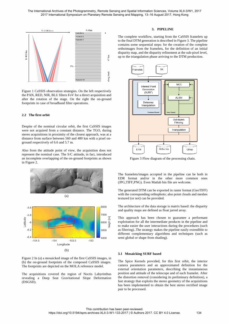
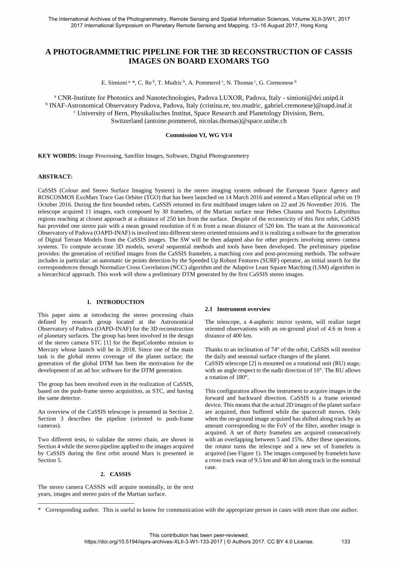
Figure 1 CaSSIS observation strategies. On the left respectively
the PAN, RED, NIR, BLU filters FoV for a direct acquisition and
after the rotation of the stage. On the right the on-ground
footprints in case of broadband filter operations.
2.2 The first orbit
Despite of the nominal circular orbit, the first CaSSIS images
were not acquired from a constant distance. The TGO, during
stereo acquisitions in proximity of the closest approach, was at a
distance from surface between 560 and 480 km with a pixel on-
ground respectively of 6.6 and 5.7 m.
Also from the attitude point of view, the acquisition does not
represent the nominal case. The S/C attitude, in fact, introduced
an incomplete overlapping of the on-ground footprints as shown
in Figure 2.
(a)
(b)
Figure 2 In (a) a mosaicked image of the first CaSSIS images, in
(b) the on-ground footprints of the composed CaSSIS images.
The footprints are depicted on the MOLA reference model.
The acquisitions covered the region of Noctis Labyrinthus
revealing a Deep Seat Gravitational Slope Deformation
(DSGSD).
3. PIPELINE
The complete workflow, starting from the CaSSIS framelets up
to the final DTM generation is described in Figure 3. The pipeline
contains some sequential steps: for the creation of the complete
orthoimages from the framelets, for the definition of an initial
disparity map, and the disparity refinement at the sub-pixel level,
up to the triangulation phase arriving to the DTM production.
Figure 3 Flow diagram of the processing chain.
The framelets/images accepted in the pipeline can be both in
EDR format and/or in the other more common ones
(JPG,TIFF,PNG). Even Matlab bin file are welcome.
The generated DTM can be exported in raster format (GeoTIFF)
with the corresponding orthophoto; also point clouds and meshes
textured (or not) can be provided.
The architecture of the data storage is matrix based: the disparity
and quality maps are defined as float jarred array.
This approach has been chosen to guarantee a performant
exploitation for all the intermediate products in the pipeline and
to make easier the user interactions during the procedures (such
as filtering)..The strategy makes the pipeline easily extendible to
different complementary algorithms and techniques (such as
semi global or shape from shading).
3.1 Mosaicking SURF based
The Spice Kernels provided, for this first orbit, the interior
camera parameters and an approximated definition for the
external orientation parameters, describing the instantaneous
position and attitude of the telescope and of each framelet. After
the distortion removal (considering its preliminary definition), a
fast strategy that exploits the stereo geometry of the acquisitions
has been implemented to obtain the best stereo rectified image
pair to be processed.
The International Archives of the Photogrammetry, Remote Sensing and Spatial Information Sciences, Volume XLII-3/W1, 2017 2017 International Symposium on Planetary Remote Sensing and Mapping, 13–16 August 2017, Hong Kong
This contribution has been peer-reviewed. https://doi.org/10.5194/isprs-archives-XLII-3-W1-133-2017 | © Authors 2017. CC BY 4.0 License.
134
Images have been rectified projecting them on a plane at a height
identified by the triangulation process of a set of tie points
extracted thanks to the SURF [[4] interest operator.
The process is as follows:
(i) calculation of the mean surface height H with respect to the
orbit by using the Spice Kernels.
(ii) projection of the framelets on a plane at the distance H.
(iii) definition of a set of tie-points (correlated) on both the
images by using the SURF operator
(iv) estimation of the actual mean height H from the triangulation
of the tie points
(v) iteration of the point coordinates extraction until H achieve a
stable value.
This bundle adjustment strategy allows to obtain the best
mosaicked images avoiding misalignments along track between
framelets which can achieve 1 pixel in case the height of the
projection surface differs of 2.2 km with respect to the real
position of the target.
The images are resampled through a bilinear interpolation. In the
overlapping regions (Figure 4) where the parallax error is
minimized, the intensity values correspond to a weighted mean
between the overlapping framelets. The weight factor changes
according to a r-cosine function from 1 to 0 in the along-track
direction (Figure 4.b).
(a)
(b)
Figure 4 In (a) mosaicking from CaSSIS first stereo framelets. In
(b) the Laplacian filter applied to an overlapping zone mosaicked
for consecutive repetitions of the procedure described, the best
alignment is reached at third iteration.
3.2 Matching phase
The pipeline proposed for the CASSIS images include three
fundamental stages:
(i) a feature based extraction of the seed points for the definition
of a starting location of the homologous points.
(ii) a parabola fitting normalized cross correlation for the initial
search for the correspondences
(iii) a Least Squares Matching [5],[6] subpixel refinement.
The workflow starts considering a number of seed (tie) points.
Through the Delaunay triangulation [[7] and the consequent
interpolation, the starting location of the corresponding points on
the slave image are determined and an approximate parallax field
is defined.
Then, an initial search for the correspondences through NCC
algorithm (accelerated using summing tables [8]) is performed
starting from the previous parallax values. Then the disparity map
is refined by the LSM.
A 2D parabola fitting of the matching cost is applied to reduce
the pixel locking effect.
The resulting disparity map is then improved using a ALSM to
achieve the sub-pixel accuracy.
A pyramidal structure is defined allowing to apply the NCC and
the ALSM algorithms at the different resolution levels.
The code is implemented in order to define through the MAtrix
User Interface (MAUI) different parameters such as: window
template dimension, search area dimension, number of pyramidal
levels, similarity functions, outlier thresholds, ALSM iterations
number.
The same MAUI allows to have a statistical and visual
representation of all the intermediate data as matrix structures:
the images, the corresponding statistical indexes (local standard
deviation, local contrast, or gradients), the disparity maps as well
as the quality maps (described by the similarity function).
3.3 Outliers rejection
Since the correlation process can encounter difficulties, the final
results can be affected by a number of mismatches and blunders.
The outliers can be detected in different ways:
- the thresholds on the NCC
- the statistical bound on the disparity maps and on its gradient
- threshold on the distance from the local mean (to avoid spike
effect)
These user-defined methods allow at each stage of the pipeline to
define the fail matching regions and preserve the continuity on
the surface.
4. TESTS
The Pipeline was tested on the first stereo pair acquired by
CaSSIS. Furthermore, two more tests were performed for
validation:
(i) HERSHEL_CRATER: based on a pair of synthetic images
generated by using the HiRISE Texturized DTM.
(ii) STC_SVS: based on a couple of images acquired during
SIMBIO-SYS STC stereo calibration on-ground phase.
Main details and results of the tests are described in the following
subsections.
The International Archives of the Photogrammetry, Remote Sensing and Spatial Information Sciences, Volume XLII-3/W1, 2017 2017 International Symposium on Planetary Remote Sensing and Mapping, 13–16 August 2017, Hong Kong
This contribution has been peer-reviewed. https://doi.org/10.5194/isprs-archives-XLII-3-W1-133-2017 | © Authors 2017. CC BY 4.0 License.
135
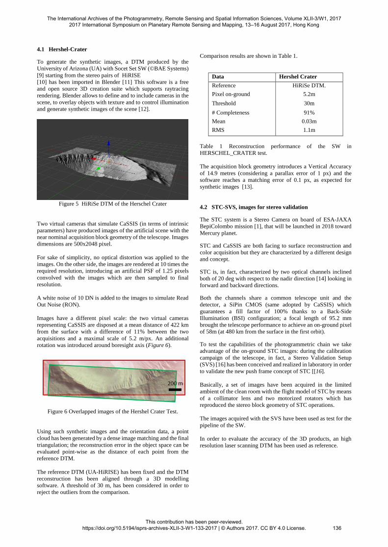
4.1 Hershel-Crater
To generate the synthetic images, a DTM produced by the
University of Arizona (UA) with Socet Set SW (©BAE Systems)
[9] starting from the stereo pairs of HiRISE
[10] has been imported in Blender [11] This software is a free
and open source 3D creation suite which supports raytracing
rendering. Blender allows to define and to include cameras in the
scene, to overlay objects with texture and to control illumination
and generate synthetic images of the scene [12].
Figure 5 HiRiSe DTM of the Herschel Crater
Two virtual cameras that simulate CaSSIS (in terms of intrinsic
parameters) have produced images of the artificial scene with the
near nominal acquisition block geometry of the telescope. Images
dimensions are 500x2048 pixel.
For sake of simplicity, no optical distortion was applied to the
images. On the other side, the images are rendered at 10 times the
required resolution, introducing an artificial PSF of 1.25 pixels
convolved with the images which are then sampled to final
resolution.
A white noise of 10 DN is added to the images to simulate Read
Out Noise (RON).
Images have a different pixel scale: the two virtual cameras
representing CaSSIS are disposed at a mean distance of 422 km
from the surface with a difference of 11% between the two
acquisitions and a maximal scale of 5.2 m/px. An additional
rotation was introduced around boresight axis (Figure 6).
Figure 6 Overlapped images of the Hershel Crater Test.
Using such synthetic images and the orientation data, a point
cloud has been generated by a dense image matching and the final
triangulation; the reconstruction error in the object space can be
evaluated point-wise as the distance of each point from the
reference DTM.
The reference DTM (UA-HiRISE) has been fixed and the DTM
reconstruction has been aligned through a 3D modelling
software. A threshold of 30 m, has been considered in order to
reject the outliers from the comparison.
Comparison results are shown in Table 1.
Data Hershel Crater
Reference HiRiSe DTM.
Pixel on-ground 5.2m
Threshold 30m
# Completeness 91%
Mean 0.03m
RMS 1.1m
Table 1 Reconstruction performance of the SW in
HERSCHEL_CRATER test.
The acquisition block geometry introduces a Vertical Accuracy
of 14.9 metres (considering a parallax error of 1 px) and the
software reaches a matching error of 0.1 px, as expected for
synthetic images [13].
4.2 STC-SVS, images for stereo validation
The STC system is a Stereo Camera on board of ESA-JAXA
BepiColombo mission [1], that will be launched in 2018 toward
Mercury planet.
STC and CaSSIS are both facing to surface reconstruction and
color acquisition but they are characterized by a different design
and concept.
STC is, in fact, characterized by two optical channels inclined
both of 20 deg with respect to the nadir direction [14] looking in
forward and backward directions.
Both the channels share a common telescope unit and the
detector, a SiPin CMOS (same adopted by CaSSIS) which
guarantees a fill factor of 100% thanks to a Back-Side
Illumination (BSI) configuration; a focal length of 95.2 mm
brought the telescope performance to achieve an on-ground pixel
of 58m (at 480 km from the surface in the first orbit).
To test the capabilities of the photogrammetric chain we take
advantage of the on-ground STC images: during the calibration
campaign of the telescope, in fact, a Stereo Validation Setup
(SVS) [16] has been conceived and realized in laboratory in order
to validate the new push frame concept of STC [[16].
Basically, a set of images have been acquired in the limited
ambient of the clean room with the flight model of STC by means
of a collimator lens and two motorized rotators which has
reproduced the stereo block geometry of STC operations.
The images acquired with the SVS have been used as test for the
pipeline of the SW.
In order to evaluate the accuracy of the 3D products, an high
resolution laser scanning DTM has been used as reference.
The International Archives of the Photogrammetry, Remote Sensing and Spatial Information Sciences, Volume XLII-3/W1, 2017 2017 International Symposium on Planetary Remote Sensing and Mapping, 13–16 August 2017, Hong Kong
This contribution has been peer-reviewed. https://doi.org/10.5194/isprs-archives-XLII-3-W1-133-2017 | © Authors 2017. CC BY 4.0 License.
136
(a)
(b)
(c)
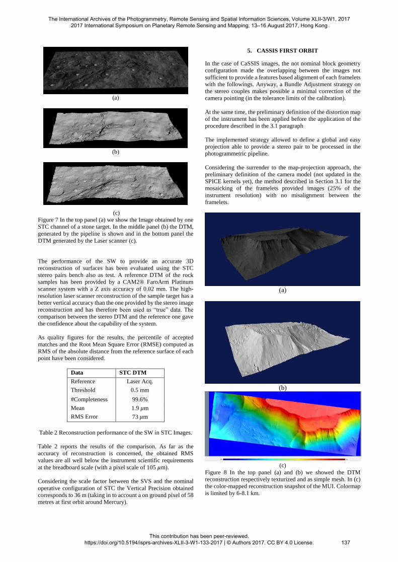
Figure 7 In the top panel (a) we show the Image obtained by one
STC channel of a stone target. In the middle panel (b) the DTM,
generated by the pipeline is shown and in the bottom panel the
DTM generated by the Laser scanner (c).
The performance of the SW to provide an accurate 3D
reconstruction of surfaces has been evaluated using the STC
stereo pairs bench also as test. A reference DTM of the rock
samples has been provided by a CAM2® FaroArm Platinum
scanner system with a Z axis accuracy of 0.02 mm. The high-
resolution laser scanner reconstruction of the sample target has a
better vertical accuracy than the one provided by the stereo image
reconstruction and has therefore been used as “true” data. The
comparison between the stereo DTM and the reference one gave
the confidence about the capability of the system.
As quality figures for the results, the percentile of accepted
matches and the Root Mean Square Error (RMSE) computed as
RMS of the absolute distance from the reference surface of each
point have been considered.
Data STC DTM
Reference Laser Acq.
Threshold 0.5 mm
#Completeness 99.6%
Mean 1.9 𝜇m
RMS Error 73 𝜇m
Table 2 Reconstruction performance of the SW in STC Images.
Table 2 reports the results of the comparison. As far as the
accuracy of reconstruction is concerned, the obtained RMS
values are all well below the instrument scientific requirements
at the breadboard scale (with a pixel scale of 105 𝜇m).
Considering the scale factor between the SVS and the nominal
operative configuration of STC the Vertical Precision obtained
corresponds to 36 m (taking in to account a on ground pixel of 58
metres at first orbit around Mercury).
5. CASSIS FIRST ORBIT
In the case of CaSSIS images, the not nominal block geometry
configuration made the overlapping between the images not
sufficient to provide a features based alignment of each framelets
with the followings. Anyway, a Bundle Adjustment strategy on
the stereo couples makes possible a minimal correction of the
camera pointing (in the tolerance limits of the calibration).
At the same time, the preliminary definition of the distortion map
of the instrument has been applied before the application of the
procedure described in the 3.1 paragraph
The implemented strategy allowed to define a global and easy
projection able to provide a stereo pair to be processed in the
photogrammetric pipeline.
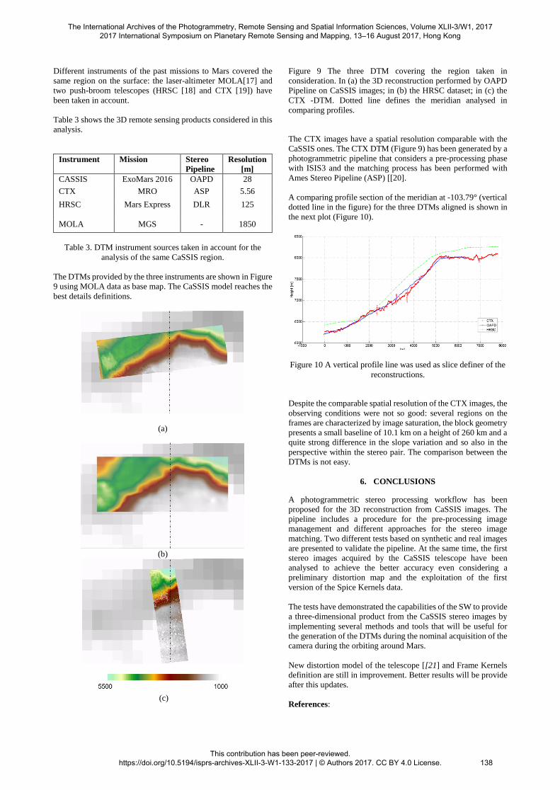
Considering the surrender to the map-projection approach, the
preliminary definition of the camera model (not updated in the
SPICE kernels yet), the method described in Section 3.1 for the
mosaicking of the framelets provided images (25% of the
instrument resolution) with no misalignment between the
framelets.
(a)
(b)
(c)
Figure 8 In the top panel (a) and (b) we showed the DTM
reconstruction respectively texturized and as simple mesh. In (c)
the color-mapped reconstruction snapshot of the MUI. Colormap
is limited by 6-8.1 km.
The International Archives of the Photogrammetry, Remote Sensing and Spatial Information Sciences, Volume XLII-3/W1, 2017 2017 International Symposium on Planetary Remote Sensing and Mapping, 13–16 August 2017, Hong Kong
This contribution has been peer-reviewed. https://doi.org/10.5194/isprs-archives-XLII-3-W1-133-2017 | © Authors 2017. CC BY 4.0 License.
137
Different instruments of the past missions to Mars covered the
same region on the surface: the laser-altimeter MOLA[17] and
two push-broom telescopes (HRSC [18] and CTX [19]) have
been taken in account.
Table 3 shows the 3D remote sensing products considered in this
analysis.
Instrument Mission Stereo
Pipeline
Resolution
[m]
CASSIS ExoMars 2016 OAPD 28
CTX MRO ASP 5.56
HRSC Mars Express DLR 125
MOLA MGS - 1850
Table 3. DTM instrument sources taken in account for the
analysis of the same CaSSIS region.
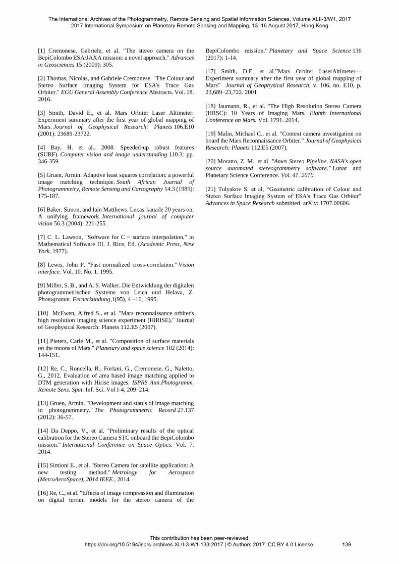
The DTMs provided by the three instruments are shown in Figure
9 using MOLA data as base map. The CaSSIS model reaches the
best details definitions.
(a)
(b)
(c)
Figure 9 The three DTM covering the region taken in
consideration. In (a) the 3D reconstruction performed by OAPD
Pipeline on CaSSIS images; in (b) the HRSC dataset; in (c) the
CTX -DTM. Dotted line defines the meridian analysed in
comparing profiles.
The CTX images have a spatial resolution comparable with the
CaSSIS ones. The CTX DTM (Figure 9) has been generated by a
photogrammetric pipeline that considers a pre-processing phase
with ISIS3 and the matching process has been performed with
Ames Stereo Pipeline (ASP) [[20].
A comparing profile section of the meridian at -103.79° (vertical
dotted line in the figure) for the three DTMs aligned is shown in
the next plot (Figure 10).
Figure 10 A vertical profile line was used as slice definer of the
reconstructions.
Despite the comparable spatial resolution of the CTX images, the
observing conditions were not so good: several regions on the
frames are characterized by image saturation, the block geometry
presents a small baseline of 10.1 km on a height of 260 km and a
quite strong difference in the slope variation and so also in the
perspective within the stereo pair. The comparison between the
DTMs is not easy.
6. CONCLUSIONS
A photogrammetric stereo processing workflow has been
proposed for the 3D reconstruction from CaSSIS images. The
pipeline includes a procedure for the pre-processing image
management and different approaches for the stereo image
matching. Two different tests based on synthetic and real images
are presented to validate the pipeline. At the same time, the first
stereo images acquired by the CaSSIS telescope have been
analysed to achieve the better accuracy even considering a
preliminary distortion map and the exploitation of the first
version of the Spice Kernels data.
The tests have demonstrated the capabilities of the SW to provide
a three-dimensional product from the CaSSIS stereo images by
implementing several methods and tools that will be useful for
the generation of the DTMs during the nominal acquisition of the
camera during the orbiting around Mars.
New distortion model of the telescope [[21] and Frame Kernels
definition are still in improvement. Better results will be provide
after this updates.
References:
The International Archives of the Photogrammetry, Remote Sensing and Spatial Information Sciences, Volume XLII-3/W1, 2017 2017 International Symposium on Planetary Remote Sensing and Mapping, 13–16 August 2017, Hong Kong
This contribution has been peer-reviewed. https://doi.org/10.5194/isprs-archives-XLII-3-W1-133-2017 | © Authors 2017. CC BY 4.0 License.
138
[1] Cremonese, Gabriele, et al. "The stereo camera on the
BepiColombo ESA/JAXA mission: a novel approach." Advances
in Geosciences 15 (2009): 305.
[2] Thomas, Nicolas, and Gabriele Cremonese. "The Colour and
Stereo Surface Imaging System for ESA's Trace Gas
Orbiter." EGU General Assembly Conference Abstracts. Vol. 18.
2016.
[3] Smith, David E., et al. Mars Orbiter Laser Altimeter:
Experiment summary after the first year of global mapping of
Mars. Journal of Geophysical Research: Planets 106.E10
(2001): 23689-23722.
[4] Bay, H. et al., 2008. Speeded-up robust features
(SURF). Computer vision and image understanding 110.3: pp.
346-359.
[5] Gruen, Armin. Adaptive least squares correlation: a powerful
image matching technique. South African Journal of
Photogrammetry, Remote Sensing and Cartography 14.3 (1985):
175-187.
[6] Baker, Simon, and Iain Matthews. Lucas-kanade 20 years on:
A unifying framework. International journal of computer
vision 56.3 (2004): 221-255.
[7] C. L. Lawson, "Software for C ~ surface interpolation," in
Mathematical Software III, J. Rice, Ed. (Academic Press, New
York, 1977).
[8] Lewis, John P. "Fast normalized cross-correlation." Vision
interface. Vol. 10. No. 1. 1995.
[9] Miller, S. B., and A. S. Walker, Die Entwicklung der digitalen
photogrammetrischen Systeme von Leica und Helava, Z.
Photogramm. Fernerkundung,1(95), 4 –16, 1995.
[10] McEwen, Alfred S., et al. "Mars reconnaissance orbiter's
high resolution imaging science experiment (HiRISE)." Journal
of Geophysical Research: Planets 112.E5 (2007).
[11] Pieters, Carle M., et al. "Composition of surface materials
on the moons of Mars." Planetary and space science 102 (2014):
144-151.
[12] Re, C., Roncella, R., Forlani, G., Cremonese, G., Naletto,
G., 2012. Evaluation of area based image matching applied to
DTM generation with Hirise images. ISPRS Ann.Photogramm.
Remote Sens. Spat. Inf. Sci. Vol I-4, 209–214.
[13] Gruen, Armin. "Development and status of image matching
in photogrammetry." The Photogrammetric Record 27.137
(2012): 36-57.
[14] Da Deppo, V., et al. "Preliminary results of the optical
calibration for the Stereo Camera STC onboard the BepiColombo
mission." International Conference on Space Optics. Vol. 7.
2014.
[15] Simioni E., et al. "Stereo Camera for satellite application: A
new testing method." Metrology for Aerospace
(MetroAeroSpace), 2014 IEEE., 2014.
[16] Re, C., et al. "Effects of image compression and illumination
on digital terrain models for the stereo camera of the
BepiColombo mission." Planetary and Space Science 136
(2017): 1-14.
[17] Smith, D.E. et al.”Mars Orbiter LaserAltimeter—
Experiment summary after the first year of global mapping of
Mars” Journal of Geophysical Research, v. 106, no. E10, p.
23,689–23,722. 2001
[18] Jaumann, R., et al. "The High Resolution Stereo Camera
(HRSC): 10 Years of Imaging Mars. Eighth International
Conference on Mars. Vol. 1791. 2014.
[19] Malin, Michael C., et al. "Context camera investigation on
board the Mars Reconnaissance Orbiter." Journal of Geophysical
Research: Planets 112.E5 (2007).
[20] Moratto, Z. M., et al. "Ames Stereo Pipeline, NASA's open
source automated stereogrammetry software." Lunar and
Planetary Science Conference. Vol. 41. 2010.
[21] Tulyakov S. et al, “Geometric calibration of Colour and
Stereo Surface Imaging System of ESA's Trace Gas Orbiter”
Advances in Space Research submitted arXiv: 1707.00606.
The International Archives of the Photogrammetry, Remote Sensing and Spatial Information Sciences, Volume XLII-3/W1, 2017 2017 International Symposium on Planetary Remote Sensing and Mapping, 13–16 August 2017, Hong Kong
This contribution has been peer-reviewed. https://doi.org/10.5194/isprs-archives-XLII-3-W1-133-2017 | © Authors 2017. CC BY 4.0 License. 139