Embed Size (px)
Citation preview

A Perspective on On-line Partial Discharge Testing of Stator Windings
Greg Stone Iris Power – Qualitrol
Outline
• Insulation deterioration processes accompanied by PD
• Early on-line PD detection in motors and generators
• Credibility issues
• Opportunities to improve test reliability

PD is a Symptom or a Cause of Several Gradual Deterioration Processes
• Loose coils/bars in the stator slot • Delamination due to thermal aging • Tracking due to partly conductive contamination • Groundwall insulation voids due to poor impregnation
with epoxy • Poor manufacture of PD suppression coatings • Inadequate spacing between bars/coils in the
endwinding On-line PD is not a symptom of endwinding vibration,
water leaks, metallic debris away from HV coils/bars, insulation problems away from high voltage coils
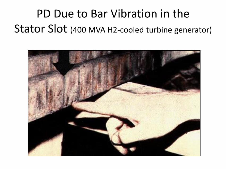
PD Due to Bar Vibration in the Stator Slot (400 MVA H2-cooled turbine generator)

PD Due to Insufficient Spacing

Electrical Tracking due to Partly Conductive Contamination

Early On-line PD Detection in Motors and Generators
• First English language reference by Johnson and Warren in 1951
• Needed on-line test to detect “slot discharges” due to loose coils in the stator slot –which tend to produce significant PD only when under load
• Used an RFCT on the generator neutral to detect PD pulse currents
• Soon after other researchers used HV capacitors on the generator output leads

Early On-line PD Detection in Motors and Generators
• PD pulses displayed on an oscilloscope or a tunable “RIV” monitor
• It was hard to permanently record the PD activity – even high speed Polaroid film was inadequate
• Experts tried to estimate PD magnitudes from a scope screen – very subjective
• Eventually solved with pulse height analyzers and phase resolved PD analyzers

The Problem of Electrical Interference
• In on-line testing, the machine is connected to the power system – and thus power system noise
• Typical plants have many sources of sparking interference (power tools, overhead cranes, electrostatic precipitators, and poor electrical connections) – most of which are normal or harmless
• Noise obscured the stator PD and made the test even more subjective, especially in hydrogen-cooled machines

The Problem of Electrical Interference
- 1 5 0
- 1 0 0
- 5 0
0
5 0
1 0 0
1 5 0
- 1 5 0
- 1 0 0
- 5 0
0
5 0
1 0 0
1 5 0
- 2 2 5 - 1 8 0 - 1 3 5 - 9 0 - 4 5 0 4 5 9 0
P u l s e D e n s i t y L i n e a r P l o tB i p o l a r M a c h i n e P D
Pu
ls
e
Ma
gn
it
ud
e
[m
V]
P h a s e A n g le [ d e g ]
0 t o 3 . 1 6 p p s 3 . 1 6 t o 1 0 p p s 1 0 t o 3 1 . 6 p p s 3 1 . 6 t o 1 0 0 p p s
1 0 0 t o 3 1 6 p p s 3 1 6 t o 1 0 0 0 p p s > 1 0 0 0 p p s
- 1 5 0
- 1 0 0
- 5 0
0
5 0
1 0 0
1 5 0
- 1 5 0
- 1 0 0
- 5 0
0
5 0
1 0 0
1 5 0
- 2 2 5 - 1 8 0 - 1 3 5 - 9 0 - 4 5 0 4 5 9 0
P u l s e D e n s i t y L i n e a r P l o tB i p o l a r T o t a l S y s t e m N o i s e
Pu
ls
e
Ma
gn
it
ud
e
[m
V]
P h a s e A n g le [ d e g ]
0 t o 3 . 1 6 p p s 3 . 1 6 t o 1 0 p p s 1 0 t o 3 1 . 6 p p s 3 1 . 6 t o 1 0 0 p p s
1 0 0 t o 3 1 6 p p s 3 1 6 t o 1 0 0 0 p p s > 1 0 0 0 p p s

The Problem of Electrical Interference
• Result is that only experienced experts could obtain correct assessments of insulation condition
• A high probability of false positives and false negatives resulted
• In late 1980s an EPRI program manager called on-line PD testing of stators “witchcraft” – and many utilities agreed
• Improved noise separation was needed to improve credibility

The Problem of Electrical Interference
Great progress has been made to make separation of PD from noise more objective:
• Move to VHF and UHF PD detection • Using time of flight to ensure signals within the
windings • Distinguishing PD from noise based on the shape of the
pulse (risetime, degree of oscillations) • Time-frequency mapping • Wavelet denoising But there were other causes of poor credibility with on-
line PD testing …….

Over claiming
Such as:
• PD can find all stator insulation problems
• That a new test is effective based on early research tests on few machines in narrow circumstances
Need more extensive testing of measurement methods with “blind” evaluation

What is “High PD”
• Unlike other apparatus, all air-cooled stators >3 kV operate with continuous PD and can tolerate it due to mica
• To assess winding condition we need to know when is the PD “too high” for the insulation system
• A single “limit” is probably not valid for all deterioration mechanisms
• For example low magnitude PD can lead to failure of the turn insulation, while high magnitude PD from stress relief coatings may never cause failure

What is “High PD”
• There is still a belief that pC as measured in machines is an absolute indicator of PD intensity and thus damage – in spite of the inductive-capacitive resonance problem and all the discussion on this in IEC and IEEE standards
• We have noted that even the trend can be problematic – PD can be initially high in new stators, and a high PD level tends to level off (or even decrease) in aged insulation even as it continues to deteriorate
Determining which machines need maintenance still needs improvement

Typical Trend in PD over Winding Life

Estimating Remaining Life
• A related topic is can we predict remaining life of the winding?
• Every machine owner wants to know this
• Many commercial claims that this is possible (although usually not using PD alone)
• Such claims should be vetted by blind testing and/or third parties

Identifying the Wrong Failure Mechanism
• Main purpose of PD testing is to identify the stators with advanced aging
• But often can also infer most likely failure process (and thus possible corrective actions and the time lines)
• If predict the wrong mechanism, the wrong repairs may be performed

Identifying the Wrong Failure Mechanism
Good progress has been made using both old and newer methods:
• Pulse polarity effect (assuming PD is in the slot) • AC phase position • Effect of load, temperature and humidity on PD activity • Phase-resolved patterns (and automated pattern
recognition) • Frequency content (with EMI) However, if there are multiple concurrent failure
processes, accurate identification is elusive
Sensor Reliability
• It is really bad if a motor or generator trips because a PD sensor fails!
• Efforts are needed to prove that PD sensors will not lead to a forced outage – IEC 60034-27-2 and IEEE 1434 has guidelines
• HFCTs and UHF antenna sensors have an advantage since not connected to the high voltage terminals

Opportunities to Improve Credibility
• Sensors not galvanically connected to the stator
• Continued research in pattern recognition both for noise separation and failure mechanism identification (but verified by third parties)
• Development of “high PD Levels” for each major failure process
• Innovation of PD quantities that better relate to the risk of stator insulation failure

Conclusion
• On-line PD monitoring is approaching a level of maturity for stator windings – more than 15,000 motors and generators are equipped
• But it has been a 60 year transition and test result credibility is still an issue


![Experience on Off-line Partial Discharge Measurement for ... · PDF fileExperience on Off-line Partial Discharge Measurement for Hydrogenerator with Capacity ... and IEC 60034-27 [2]](https://img.pdfslide.us/doc/110x75/5a9097967f8b9adb648e651c/experience-on-off-line-partial-discharge-measurement-for-experience-on-off-line.jpg)