Embed Size (px)
Citation preview


Summary New network technologies have changed the ways how people interact and collaborate over a distance. The understanding of such interaction is, however, still limited. This thesis discusses how new groupware applications can be built that support such networked groups. The main focus thereby is not on how to support application specific tasks – which is in many aspects comparable to single user support – but on the group specific aspects like group formation and group maintenance. The approach presented in this thesis sheds light on the problem of groupware development by taking a closer look at theoretic approaches to design. Especially, the situatedness of design as it is propagated by the philosopher Martin Heidegger and the architect Christopher Alexander motivate that groupware development has to pay special attention to the group's situation. Empowering the end-users to express their needs in a specific group situation is therefore crucial to any groupware development. The Oregon Software Development Process presented in this thesis reflects these ideas. It fosters the communication and interaction between developers and end-users during all phases of software development and ensures that end-user involvement and end-user tailorability is achieved. Groupware patterns serve as an educational means for empowering end-users to behave like groupware development experts. They describe how to design social interaction in groupware systems as well as technical aspects of groupware systems. A selection of groupware patterns is presented in this thesis. The approach is validated through analyzing its impact in different case studies: the first case is a two year development project of the collaborative learning system CURE involving six developers and a large user community; the second case describes the application in three smaller student projects. About the Author Till Schümmer, born 1973 in Frankfurt/Main, Germany, studied computer science at the Darmstadt University of Technology from 1994 to 1999 finishing with a diploma in computer science. From 1999 to 2002, he participated in the DFG supported PhD program "Infrastructures for Electronic Commerce" at the Darmstadt University of Technology. During his years in Darmstadt, Till collaborated with the CONCERT division of the Fraunhofer IPSI institute where he participated in the development of the COAST groupware framework and several applications for supporting group interaction in work settings and in e-commerce contexts. In 2002, he moved to the FernUniversität in Hagen, where he developed groupware applications that support distributed students in their learning process. His insights of 10 years of groupware development are captured in this thesis for which Till received a Dr. rer. nat. in computer science in July 2005.


Preface
Groupware is becoming increasingly important as a means for supporting collabo-rative work in distributed organizations. Although we find a plethora of groupwaresystems in the research domain, only few groupware application are widely used.One reason for this deficit may be the problem of matching the ever-changing end-users’ needs with the characteristics of a groupware system. Researchers proposeseveral approaches to this problem: from customized development to end-user tai-loring. However, no adequate approach has yet been demonstrated.
This book presents a solution that allows end-users to actively participate ingroupware development. The resulting groupware meets the initial requirements ofthe users and can be tailored as requirements and practices will inevitably changeduring later use. The solution is rooted in both, agile software development processesand pattern languages. Based on an in-depth review of existing theories on designand problem solving, an approach consisting of two components is constructed:Firstly, an adapted agile software development process, called the Oregon process,is presented, which combines end-user participation with rapid, iterative softwaredevelopment. Secondly, a pattern language is presented, which enables end-usersto understand and participate in the design of the groupware. Together, thesecomponents facilitate communication between end-users and developers, and enableend-users to drive the development process.
The approach is validated through a detailed case study. The case shows that theapproach was successfully used in a 2 years larger groupware development projectat a distance learning university.
The book provides the reader, who is interested in successful groupware develop-ment, with a description of the process and the pattern language. The case study andmany examples help the reader to appropriate the method to other usage contexts.
Hagen, July 2005
Prof. Joerg M. Haake
v

vi

Abstract
The development of groupware applications is still a difficult task. One main reasonis that both developers and end-users are not aware of possible solutions for sup-porting group interaction. A second aspect is that group interaction involves manyusers, which makes the definition of requirements difficult.
Developers and end-users thus need to be supported in the requirements elici-tation and the design of tools that help to satisfy these requirements. This thesisdiscusses groupware development processes from three perspectives: (1) the abstractview on development that is not bound to the specific nature of the developed ar-tifact, (2) the software development perspective that focuses on processes and toolsfor the development of software, and (3) the groupware development perspective,which brings together software development aspects with social aspects and thusaddresses the task of groupware development from a socio-technical view.
We first derive requirements from the abstract view on development that ismainly influenced by the theories of the architect Christopher Alexander. Thesetheories suggest that end-users should be in control over the development process.To reach this level of control, they have to be educated regarding possible good prac-tices – the patterns – for reshaping their environment. The goal is that end-usersshape their environment in structure-preserving transformations that are modifi-cations that help to increase the set of satisfied requirements by keeping existingstructures intact or whole, as Alexander would call it.
These core requirements are then related to current software and groupware de-velopment processes. A special focus is put on evolutionary processes, agile methods,and participatory design approaches. We will show that these processes, methodsand approaches solve specific aspects of the requirements, but that there is still theneed for a process that supports groupware development in a way so that end-userscan construct structure-preserving transformations.
To fill this gap, we propose a new development process, the Oregon SoftwareDevelopment Process. It fosters end-user participation, evolutionary growth, andreuse and exchange of design knowledge. This process supports development ac-tivities so that the different steps in the development lead to structure preservingtransformations. This process advocates the use of end-user centered patterns asthe most important artifacts during the development of socio-technical systems.
To illustrate the application of the process we first present a small set of patternsfrom a pattern language for group formation based on enhanced group awareness.It addresses a small subset of problems in groupware development (the group for-
vii

viii ABSTRACT
mation phase). The application of these and other patterns from a larger groupwarepattern language is demonstrated for the development of the collaborative learningenvironment CURE. We will discuss the different levels of participation and themeans for educating end-users in the design of collaborative systems. Experiencesfrom this project show how the iterative application of groupware patterns leadsto a coherent design of a collaborative application through a sequence of structurepreserving transformations. The educative support of the patterns is further investi-gated by reporting on student projects in which students that were not familiar withgroupware development designed systems for supporting different types of groups.
Finally, the main contributions of this thesis are summarized. They are
– the introduction of the Oregon Software Development Process that fosters end-user participation,
– a new format for design patterns that is especially focussed on end-users,
– a pattern language for group formation based on enhanced group awarenessand the presentation of selected patterns in an elaborated format,
– a collection of thumbnails of additional patterns from a pattern language forgroupware development,
– a case study of applying the process and the patterns in a participatory designprocess of the collaborative learning platform CURE, and
– the evaluation of pattern languages regarding the role of structure preservingtransformation in the context of the CURE project.

Zusammenfassung
Die Entwicklung von kooperativen Systemen ist nach wie vor eine anspruchsvolleAufgabe. Einer der Grunde hierfur ist, dass sowohl Anwender als auch Entwicklerhaufig keinen umfassenden Uberblick uber den Stand der Forschung im Bereich derEntwicklung kooperativer Anwendungen besitzen. Insbesondere haben weder An-wender noch Entwickler ausgiebige Erfahrungen mit dem Einsatz kooperativer Sys-teme und mit deren Auswirkungen auf die Interaktion in der Gruppe. Neben diesemMangel an Erfahrungen tragt ein weiterer Aspekt zur Komplexitat bei: Muss bei derEntwicklung von Einbenutzeranwendungen lediglich die Interaktion eines Benutzersmit einem Computersystem betrachtet werden (HCI), so haben wir es bei koope-rativen Systemen immer mit einer Gruppe von Benutzern zu tun, die mittels desSystems miteinander interagieren mochten. Es geht also sowohl darum, die Interakti-on eines Benutzers mit dem Computersystem zu strukturieren, als auch darum, denGruppenprozess zu definieren und zu unterstutzen. Neben der Mensch-Maschine-Interaktion (HCI) muss also auch die Mensch-Maschine-Mensch-Interaktion (HCHI)betrachtet werden. Alle diese Faktoren machen die Definition von Anforderungenschwierig, was das Hauptproblem fur Entwickler und Anwender bei der Erstellungkooperativer Systeme ist.
Es bedarf deshalb eines Ansatzes, der Entwickler und Anwender beim Auffindender Anforderungen und bei der Entwicklung von Werkzeugen, die diese Anforde-rungen erfullen, unterstutzt. Im Rahmen dieser Dissertation werden als Reaktionauf diese Erkenntnis Entwicklungsprozesse fur kooperative Anwendungen aus dreiverschiedenen Perspektiven betrachtet:
1. Die abstrakte Sicht auf Entwicklungsprozesse, die nicht an eine bestimmte Artvon zu entwickelnden Systemen gebunden ist. Hierunter fallen theoretischeUberlegungen zum Verstandnis von Entwurfsprozessen, wie sie in den Philoso-phien von Martin Heidegger (Situiertheit allen Handelns und die Theorie desBruchs), Jan Christian Smuts (Holismus), Donald Schon (Reflexion) oder Chri-stopher Alexander (Strukturerhaltende Transformationen unter Zuhilfenahmevon Entwurfsmustern) zu finden sind.
Die abstrakte Sicht dient als Basis fur die Definition von Anforderungen furein ideales Vorgehensmodell fur die Entwicklung kooperativer Systeme. Hierbeiliegt ein besonderer Fokus auf den Theorien von Christopher Alexander. Dieserlegte nahe, dass der Benutzer stets die Kontrolle uber den Entwicklungsprozessbehalten solle. Da der Benutzer seinen Kontext und seine Wunsche am besten
ix

x ZUSAMMENFASSUNG
kennt, diese jedoch oft nur schwer kommunizieren kann, sollte der Benutzer indie Lage versetzt werden, seine Umgebung selbst zu gestalten. Fur Alexander,einem Architekten, lag das Augenmerk dabei zunachst auf der Gestaltung vonGebauden. Die neuesten Theorien Alexanders schlagen jedoch eine Ausweitungauch auf andere Gestaltungsfelder vor.
Damit der Benutzer die Kontrolle uber seine Umgebung behalten kann, ist eserforderlich, dass er mit kognitiven Werkzeugen ausgerustet wird, die es ihmerlauben, gut durchdachte Entwurfsentscheidungen zu treffen. Entwurfsmustersind ein solches Werkzeug. Sie bilden den Benutzer, indem sie wiederkehrendeProbleme und deren Losungen so darstellen, dass sowohl die Losung als auchdie Begrundung fur die Losung einsichtig wird.
Alexander zeigt weiter, dass einige Entwurfsmuster Transformationen des Kon-texts des Benutzers beschreiben, die den Charakter der Umgebung intakt las-sen. Wichtige Merkmale, die fur das bisherige Funktionieren der Umgebungverantwortlich waren, durfen nicht verletzt werden. Aspekte der Umgebung,die bisher nicht perfekt funktionierten, mussen hingegen verbessert werden.Sofern Entwurfsmuster dies gewahrleisten, stellen Sie fur Alexander struktur-erhaltende Transformationen dar.
Da solche Transformationen die Ganzheit des Systems stets starken, solltees das Ziel eines Entwicklungsprozesses sein, genau solche Transformationenhervorzubringen.
2. Die Theorie der Software-Entwicklungsprozesse. Diese Sicht nimmt vor allemProzesse und Werkzeuge fur die Entwicklung von Computersystemen in denBlick. Zentrale betrachtete Modelle sind
– sequenzielle Modelle (z.B. das Wasserfall-Modell),
– iterative Modelle (z.B. der Unified Process), in denen die Entwicklung desSystems in mehreren Iterationsschritten durchlaufen wird, bei denen jedeIteration eine zusatzliche Annaherung an die Ziele der Benutzer bringt,
– agile Methoden (z.B. eXtreme Programming), die auf extrem kurze Ite-rationen und eine vermehrte Kommunikation zwischen Benutzern undEntwicklern ausgerichtet sind und
– partizipative Vorgehensmodelle, bei denen die Interaktion mit dem Be-nutzer und seine Einbindung in den Prozess im Vordergrund stehen.
Erganzt werden diese drei Sichten durch die Betrachtung von Software-Ent-wurfsmustern, die bei der Softwareentwicklung eine wichtige didaktische Rollespielen.
In der Arbeit zeigen wir, dass die Modelle alle jeweils nur Teilaspekte der An-forderungen erfullen. So haben sequenzielle, iterative und agile Modelle einenFokus auf der Unterstutzung der technischen Aufgaben im Lebenszyklus einesEntwicklungsprojektes. Partizipative Vorgehensmodelle und Entwurfsmusterlegen hingegen besonderen Wert auf die Einbeziehung des Benutzers.
ZUSAMMENFASSUNG xi
Entwurfsmuster unterstutzen den Benutzer bei der Erarbeitung und der Er-schließung von Losungskonzepten und spielen daher eine wichtige didaktischeRolle.
3. Vorgehensmodelle fur die Entwicklung kooperativer Systeme bilden die dritteSicht. Hierbei liegt der Fokus auf den Anpassungen, die vorgenommen wurden,um der Komplexitat der Entwicklung kooperativer Anwendungen im Vorge-hensmodell Rechnung zu tragen. Dabei untersuchen wir eine soziotechnischeSicht auf den Entwicklungsprozess, die sowohl die Interaktion zwischen Benut-zern als auch die Gestaltung der Technologie im Blickfeld hat.
Auch bei den Modellen fur die Entwicklung kooperativer Systeme gibt es kei-nen Vertreter, der sowohl die Aufgaben im Lebenszyklus des Entwicklunspro-zesses als auch die didaktischen Anforderungen hinsichtlich der Kompetenzer-weiterung der Benutzer erfullt.
Um diese Lucke zu fullen, stellen wir in dieser Arbeit einen neuen Entwicklungs-prozess vor: den Oregon Software Development Process (OSDP). Dieser legt Wertauf
– eine moglichst umfassende Einbindung des Benutzers, bei der der Benutzer dieRolle eines gebildeten Designers und Entwicklers spielen kann,
– das evolutionare Wachstum des Systems unter Berucksichtigung von struktur-erhaltenden Transformationen, und
– den Austausch von Wissen und Erfahrungen sowohl zwischen Entwicklern alsauch zwischen Benutzern.
Eine wichtige Rolle spielen im OSDP Entwurfsmuster, die in einer sowohl fur denEntwickler als auch fur den Benutzer verstandlichen Sprache verfasst sind.
Eine kleine Auswahl solcher Entwurfsmuster ist in der Arbeit enthalten. Es han-delt sich hierbei um eine Sammlung von Entwurfsmustern zur Unterstutzung vonGruppenbildung in kooperativen Systemen auf Basis einer besseren gegenseitigenWahrnehmung der Benutzer. Hierbei wird ein besonders wichtiger Aspekt koopera-tiver Anwendungen in den Blick genommen: Die Phase der Gruppenbildung, die dieBasis fur jede Kooperation in kooperativen Anwendungen ist. Die in voller Langedargestellten Entwurfsmuster werden durch Kurzformen weiterer Entwurfsmusterzur Unterstutzung der Entwicklung kooperativer Systeme erganzt.
Der Ansatz – die Kombination von OSDP und Entwurfsmustern fur kooperativeSysteme – wird abschließend anhand einer Fallstudie validiert. Hierbei handelt essich um den Einsatz des Prozesses und der Entwurfsmuster im Rahmen des Ent-wicklungsprojektes CURE, in dem eine kooperative Lernplattform fur die FernU-niversitat in Hagen entwickelt wurde. Wir zeigen, wie Benutzer auf verschiedenenEbenen in den Entwicklungsprozess eingebunden wurden: in der Konzeptionsphase,indem sie Erfahrungen und Szenarien aus ihrem Kooperationsumfeld beisteuern, inder Entwicklungsphase, wo sie Anforderungen definieren und gewichten, und in der

xii ZUSAMMENFASSUNG
Anpassungsphase, in der sie kleine technische Anderungen und vor allem Anderun-gen im Gruppenprozess selbst gestalten und umsetzen. Unsere Erfahrungen zeigen,dass Entwurfsmuster eine wichtige Rolle in der Kommunikation und dem Handelnder beteiligten Personen gespielt haben. Das Ergebnis dieses Projektes zeigt, dassdie iterative Anwendung von Entwurfsmustern zu einem koharenten und in sichstimmigen kooperativen System fuhrt. Dabei wird deutlich, dass es sich hierbei umstrukturerhaltende Transformationen handelt. Eine sehr positive Akzeptanz durchdie Benutzer ist ein weiterer Indikator fur die Qualitat des mittels des OSDP erstell-ten Systems.
Die didaktische Wirkung der Entwurfsmuster wird danach anhand von dreistudentischen Projekten demonstriert. Hierbei handelt es sich um Diplom- undBachelor-Arbeiten, in denen Studenten die Entwurfsmuster fur die Entwicklungoder Erweiterung eines kooperativen Systems eingesetzt haben. Die Erfahrungender Betreuer und die Reaktionen der Studenten zeigen, dass die Entwurfsmustereinen wichtigen Beitrag zum Verstandnis der Anwendungsentwicklung geleistet ha-ben. Allerdings zeigen sie auch auf, dass zusatzliche Expertise bei der Entwicklungvon technischen Komponenten notig ist. Entwurfsmuster konnen somit nicht als All-heilmittel gegen defizitare Grundfertigkeiten im Kontext der Software-Entwicklungbetrachtet werden.
Abschließend konnen die Hauptbeitrage dieser Arbeit wie folgt zusammengefasstwerden:
– Die Arbeit schlagt den Oregon Software Development Process vor, in dem vorallem Benutzerbeteiligung unterstutzt wird,
– sie definiert ein Format fur Entwurfsmuster, das vorrangig fur die Nutzungdurch Endbenutzer (also Laien auf dem Gebiet der Softwaretechnik) ausgelegtist,
– sie stellt eine Sammlung von Entwurfsmustern zur Unterstutzung der Grup-penbildung mittels verbesserter gegenseitiger Wahrnehmung der Benutzer vorund beschreibt ausgewahlte Entwurfsmuster in ihrer vollen Lange.
– Die vollstandigen Entwurfsmuster werden durch ein Sammlung von Kurzfas-sungen von Entwurfsmustern fur die Entwicklung kooperativer Systeme er-ganzt.
– Eine Fallstudie zeigt den Einsatz der Entwurfsmuster an einem konkreten Bei-spiel, der kooperativen Lernplattform CURE.
– In der Fallstudie wird schließlich deutlich, wie strukturerhaltende Transforma-tionen bei der Entwicklung eines kooperativen Systems hilfreich sein konnen.

Acknowledgements
This thesis is the result of many years of research in the context of groupwaresystems. Many people accompanied me on my path of research. Now it is time forme to express my gratitude for the numerous interactions that helped me to clarifymy thoughts presented in this thesis.
Thanks are due to my advisor, Jorg M. Haake. He employed me 1995 as aresearch student in the CONCERT research division of the Fraunhofer IPSI. Sincethen he was the most constant companion and followed my research for the last 10years until now. His constructive criticism was challenging for improving this work.
The employment at the CONCERT division opened the opportunity for me tocollaborate in an ambitious research team and contribute to the groupware devel-opment framework COAST. As member of the COAST development team togetherwith Christian Schuckmann, my brother Jan Schummer, Hans Scholz, and HolgerKleinsorgen, I could experience the new directions for groupware development andgained insights into many technical issues that had to be considered when buildingcollaborative applications.
In 1999, I first met Alejandro Fernandez who moved from Argentina to Germanyto work at the CONCERT division. He was the person who introduced me to theearly work of Christopher Alexander. This encounter was pathbreaking for myfuture research. Other colleagues who accompanied these first steps in the directionof a pattern-oriented view on groupware development were Robert Slagter (from theTelematica Institute in the Netherlands) and Torsten Holmer who also worked atthe CONCERT division. Robert triggered me to consider the aspects of tailoringand end-user involvement as important parts of groupware development. Torstencontributed his incredible enthusiasm for new ideas.
I appreciate the support from my current colleagues at the distributed systemsgroup at the FernUniversitat in Hagen. Stephan Lukosch jumped on the train ofgroupware patterns research and became the most important discussion partnerregarding the development and application of groupware patterns. Thanks are dueto Mohamed Bourimi, Anja Haake, and Britta Landgraf (in alphabetical order) whoagreed to participate as developers in the CURE development project. WolframSchobert contributed to the development of the collaborative pattern editor CoPE.He burned the midnight oil when I had the idea of new functionality and wanted todemonstrate it on the other day (e.g. at the CHI2004 workshop on HCHI patterns).
Special thanks are due to my shepherds at various EuroPLoP conferences (inchronological order): Antonio Rito Silva, Martine Devos, Kristian Elof Sørensen,
xiii

xiv ACKNOWLEDGEMENTS
Joseph Bergin, Andreas Ruping, Lise B. Hvatum, and Alan O’Callaghan. All ofthem provided invaluable feedback to the patterns presented in this thesis. Specialthanks are due to Joseph Bergin (Pace University – New York) for accepting theinvitation to participate in my PhD committee.
Above all, I have to thank my beloved wife Jutta and my two sons Noah andLiam. Jutta gave her invaluable mental support and helped to create an environmentin which this work could be written. My sons had to miss their father for severalmonths while I was writing the final version of this thesis – with the side effect thatNoah (2 years) is now able to perfectly pronounce the German word Doktorarbeit.1
To express my thanks to all of you and the innumerable researchers who chal-lenged me in discussions, I decided to write this thesis in plural voice. Even thoughsome contribution were only small bricks in the building of this thesis, they allbrought me forward in my evolving my ideas of groupware development. Thankyou!
1German for PhD thesis.

Contents
Chapter 1 Introduction 1
1.1 Motivation . . . . . . . . . . . . . . . . . . . . . . . . . . . . . . . . . 1
1.2 Problem Statement . . . . . . . . . . . . . . . . . . . . . . . . . . . . 4
1.3 Approach . . . . . . . . . . . . . . . . . . . . . . . . . . . . . . . . . 5
1.4 Organization of this thesis . . . . . . . . . . . . . . . . . . . . . . . . 5
Chapter 2 Theory of Development Activities 7
2.1 Heidegger – Understanding Situatedness . . . . . . . . . . . . . . . . 10
2.2 Alexander – The Synthesis of Form . . . . . . . . . . . . . . . . . . . 11
2.3 Rittel and Webber – Wicked Problems . . . . . . . . . . . . . . . . . 14
2.4 Schon – Reflection in Action . . . . . . . . . . . . . . . . . . . . . . . 15
2.5 Alexander – Patterns in the Context of Design . . . . . . . . . . . . . 17
2.5.1 Garfinkel – Ethnomethodology . . . . . . . . . . . . . . . . . . 19
2.6 Alexander – The Oregon Experiment . . . . . . . . . . . . . . . . . . 21
2.7 The Scandinavian Approach – Participatory Design . . . . . . . . . . 24
2.8 Alexander – The Nature of Order . . . . . . . . . . . . . . . . . . . . 25
2.9 Takeuchi and Nonaka – The Rugby Approach . . . . . . . . . . . . . 31
2.10 Groupware Development Requirements . . . . . . . . . . . . . . . . . 33
Chapter 3 State of the Art 39
3.1 Software Development Processes . . . . . . . . . . . . . . . . . . . . . 39
3.1.1 Sequential Non-Iterative Development . . . . . . . . . . . . . 40
3.1.2 Iterative Development Processes . . . . . . . . . . . . . . . . . 45
3.1.3 Agile Methods for Software Development . . . . . . . . . . . . 49
3.1.4 Participatory Design and End-User Development . . . . . . . 60
3.1.5 Patterns in the Context of Software Development . . . . . . . 65
3.1.6 Discussion of Software Development Processes . . . . . . . . . 76
3.2 Groupware Development Processes . . . . . . . . . . . . . . . . . . . 78
3.2.1 A critical review of Dewan’s waterfall process model for group-ware development . . . . . . . . . . . . . . . . . . . . . . . . . 78
xv

xvi CONTENTS
3.2.2 Agile Processes for Groupware Development . . . . . . . . . . 81
3.2.3 Application of Participatory Design Methods . . . . . . . . . . 82
3.2.4 CSCW Patterns . . . . . . . . . . . . . . . . . . . . . . . . . . 85
3.3 Summary of the first part . . . . . . . . . . . . . . . . . . . . . . . . 91
Chapter 4 Approach 95
4.1 The Oregon Software Development Process . . . . . . . . . . . . . . . 95
4.1.1 Conceptual Iteration . . . . . . . . . . . . . . . . . . . . . . . 95
4.1.2 Development Iteration . . . . . . . . . . . . . . . . . . . . . . 98
4.1.3 Tailoring Iteration . . . . . . . . . . . . . . . . . . . . . . . . 101
4.1.4 The relation between the different iteration types . . . . . . . 102
4.1.5 Requirements addressed by OSDP . . . . . . . . . . . . . . . . 102
4.1.6 Comparison to the State of the Art . . . . . . . . . . . . . . . 105
4.2 The Pattern Representation . . . . . . . . . . . . . . . . . . . . . . . 106
4.2.1 Single Pattern Representation . . . . . . . . . . . . . . . . . . 106
4.2.2 Pattern Abstraction Scale . . . . . . . . . . . . . . . . . . . . 112
Chapter 5 The Pattern Language 113
5.1 Importance of Group Formation . . . . . . . . . . . . . . . . . . . . . 113
5.2 A Pattern Language . . . . . . . . . . . . . . . . . . . . . . . . . . . 116
5.2.1 Overview . . . . . . . . . . . . . . . . . . . . . . . . . . . . . 116
5.2.2 From Shared Data to Shared Work . . . . . . . . . 120
5.2.3 Local Awareness . . . . . . . . . . . . . . . . . . . . . 127
5.2.4 Presence Indicator . . . . . . . . . . . . . . . . . . . . 135
5.2.5 User List . . . . . . . . . . . . . . . . . . . . . . . . . . 141
5.2.6 Gaze Over the Shoulder . . . . . . . . . . . . . . . . 145
5.2.7 Elephant’s Brain . . . . . . . . . . . . . . . . . . . . . 150
5.2.8 Daily Report . . . . . . . . . . . . . . . . . . . . . . . . 158
5.2.9 Hello Hello . . . . . . . . . . . . . . . . . . . . . . . . 163
5.3 Summary . . . . . . . . . . . . . . . . . . . . . . . . . . . . . . . . . 169
Chapter 6 Experiences 171
6.1 Observation Method . . . . . . . . . . . . . . . . . . . . . . . . . . . 171
6.2 Context of the CURE Project . . . . . . . . . . . . . . . . . . . . . . 174
6.3 Conceptual Iterations in CURE . . . . . . . . . . . . . . . . . . . . . 175
6.3.1 Results from the Conceptual Iterations . . . . . . . . . . . . . 178
6.4 Development Iterations in CURE . . . . . . . . . . . . . . . . . . . . 179
6.4.1 A sequence shaping the collaboration environment . . . . . . . 180
6.4.2 A sequence addressing group awareness . . . . . . . . . . . . . 185

CONTENTS xvii
6.4.3 A sequence addressing privacy and group formation . . . . . . 192
6.4.4 Results from the Development Iterations . . . . . . . . . . . . 202
6.5 Tailoring Iterations in CURE . . . . . . . . . . . . . . . . . . . . . . 205
6.5.1 The Hello Hello pattern . . . . . . . . . . . . . . . . . . . . . 205
6.5.2 The emergence of CSCL patterns during tailoring iterations . 206
6.5.3 Results from Tailoring Iterations . . . . . . . . . . . . . . . . 209
6.6 Student Projects . . . . . . . . . . . . . . . . . . . . . . . . . . . . . 210
6.6.1 Results from the Student Projects . . . . . . . . . . . . . . . . 213
6.7 Observations Made by Peer Reviewers and Shepherds . . . . . . . . . 214
6.8 Summary . . . . . . . . . . . . . . . . . . . . . . . . . . . . . . . . . 216
Chapter 7 Conclusions and Future Work 219
7.1 Summary . . . . . . . . . . . . . . . . . . . . . . . . . . . . . . . . . 219
7.2 Main Contributions . . . . . . . . . . . . . . . . . . . . . . . . . . . . 221
7.3 Future Work . . . . . . . . . . . . . . . . . . . . . . . . . . . . . . . . 222
Appendix A Additional Thumbnails 225
Appendix B The CoPE Environment 247
B.1 Linking Patterns in a Pattern Language . . . . . . . . . . . . . . . . 247
B.2 Example Diagram . . . . . . . . . . . . . . . . . . . . . . . . . . . . . 251
Appendix C Tailoring Mechanisms in CURE 253
Bibliography 259
Index 278
xviii CONTENTS

Chapter 1
Introduction
New network technologies have changed the ways how people interact and collabo-rate over a distance. By staying connected over a network, new ways of collaborativework could evolve. Instead of working face-to-face most of the time and rare commu-nication with remote people, today many people collaborate with remote peers viathe Internet. In the work domain, employees in distributed companies collaboratein distributed work groups, workers in distant parts of a virtual organization formdynamic ad-hoc teams for a step in the production process, and people participate invirtual communities to increase their professional capabilities, e.g. in communitiesof practice (e.g., Wenger (1998)). This development is also visible in private life,where users participate in use communities of interest and communities of purposeto make their life easier or more interesting.
This thesis discusses how new groupware applications can be built that supportsuch networked groups. The main focus thereby is not on how to support applicationspecific tasks – which is in many aspects comparable to single user support – buton the group specific aspects like group formation and group maintenance.
1.1 Motivation
Consider as an introductive example the case of online communities. Preece (2000)defines online communities as a set of “people, who interact socially as they striveto satisfy their own needs or perform special roles, such as leading or moderating.”These people share interests or needs, which make up the purpose of the community.They use group policies (i.e., rules and assumptions) to guide social behavior andcomputer systems to mediate the interaction. An early example is the legendaryWELL (Rheingold, 1998).
Sometimes the members also/only meet in person. In this case, the role of thetechnology is mainly reduced to bringing people together. Examples are flashmobs(e.g., the Birmingham flashmob in 2003 – cf. (Revell, 2004)) where large groupsof people gather at a predefined time in public spaces to have fun and performobjectively meaningless actions.
An increasing number of community providers has realized that virtual com-
1

2 CHAPTER 1. INTRODUCTION
munities can become very binding, if they reach the phase of social involvement.Rovai (2002), further defines four characteristics of online communities: spirit, com-monality of expectation and goals, trust and interaction. These characteristics arecommon to most group processes. The community needs a spirit that helps mem-bers to distinguish themselves from other people. The spirit is often supported by ashared set of goals. Community members have to establish trust in order to interactfreely. Interaction in turn helps to grow trust.
There are different classifications of communities. Most classifications distinguishcommunities of interest, communities of purpose, and communities of practice (cf.Marathe (1999), Carotenuto et al. (1999)).
Members of a community of interest share the same interests in a topic (and of-ten a common background). Examples are discussion groups on television shows orpeople interested in planets of the solar system. Some authors (e.g. Carotenuto et al.(1999)) also define communities of passion, which are very close to communities ofinterest. The difference is that the members are more involved in the community’stopic up to the point where they become passionate advocates. Actually, a com-munity of interest can become a community of passion. An example is a discussiongroup on a TV show that became a fan club of the show’s host.
Communities of purpose consist of members who share a common (short term)goal. For instance, customers at a virtual bookstore share the goal of finding andbuying books. They all have to go through the same process (i.e. selecting theitem and checking out) and they can help one another reaching the goal. Thus, thecommunity of purpose has a functional purpose and it may dissolve after the goalis reached. In contrast to communities of interest, the members don’t necessarilyshare the same interests and therefore, they are not likely to start activities thatexceed the community’s purpose (Carotenuto et al., 1999).
If the members of a community share a common profession, the community iscalled a community of practice. Their members reflect on the way how they performtheir tasks and enhance their ways of working in a community learning process. Sincethe community’s topic is the member’s profession, members are normally highlyinvolved in such communities. Concrete communities of practice are for instanceSmalltalk programmers who meet in a Smalltalk users group to shape the process ofprogramming. In some cases, it makes sense that the community is established bythe merchants. Given the example of the Smalltalk users group, the main vendor hasbeen heavily involved from the beginning. The well known experts are employees ofthe company, and their involvement in the online discussions is beneficial for bothparties (customers and vendor): the customers can get help from the experts, andthe vendor can steer the discussion regarding his business plans (carefully up to aspecific degree; too much advertising would put off the customers).
Marathe (1999) adds another type of community: a community of circumstances,which is defined by common circumstances such as current life situations, e.g. chil-dren reaching puberty. Interaction in these communities is often personally focusedand third parties are not involved in the community. Therefore, these communitiesmay not easily be influenced, but they can lead to strong bindings to a seller, if this

1.1. MOTIVATION 3
seller is present in important life stages.
While technology that supports the above types of groups in their tasks (e.g.,exchange of messages and documents) is widely available, fewer attention has beenon the need of social group interaction, e.g. the need of users to find relevant peersor the need of users to establish trust. But this social group interaction is one ofthe most important issues in the design of successful groupware.
A famous definition of the term groupware defines groupware systems as “inten-tional group processes plus software to support them” (Johnson-Lenz and Johnson-Lenz, 1981). This definition includes different aspects that we have to consider whendesigning groupware solutions:
– The core of the definition is the group. A group of users wants to interact usinggroupware. Naturally, the members of this group should play an importantrole during the design of groupware. The groupware design has the purpose tocreate a solution, which satisfies the user’s needs. Thus, end-user requirementshave to be the central issue during groupware design.
– The group interacts in an intentional group process. The interaction betweenhumans thus needs to play an important role during the design of any group-ware solution. It has to become clear who interacts with whom. It has to beconsidered how strict the intentional group process is, ranging from unplannedinteraction in virtual communities up to formally structured workflows in adistributed workgroup.
– The process is supported by software. The fact that software is mentionedat a third place here emphasizes that the software itself should be a support-ive means to ease the interaction between humans. The software should beadapted to the users’ needs to best fulfill its supportive role. At this point thesoftware developer comes into play. As the software supports the group pro-cess, the software developer should support the users in adapting or creatinga software that fits the process.
Compared to a focus on design that has the goal of supporting the group in themanipulation of content, support for social group interaction needs a larger focus onthe relations between users. Tools for manipulation are in most cases used by oneuser (even in collaborative systems). So, they affect the relation between the userand the shared artifacts. Social interaction, on the other hand, affects the relationbetween users and needs to address issues like trust and privacy. The focus shouldthus be on human-computer-human interaction (HCHI), while the design of toolsfor the manipulation of artifacts mainly affects human-computer interaction. Thedesign of tools therefore focuses on the interaction of the user with the artifact andconsiders the human-human interaction as a marginal aspect.
To provide customized designs of groupware mechanisms, we have to make use ofa design process that is flexible enough to adapt to the group’s needs. Experienceswith the design of single user applications have already shown that many softwaredevelopment projects fail because of requirements inadequacies (Dorfman, 1997). In

4 CHAPTER 1. INTRODUCTION
such cases, the customer is typically involved in the early stages of the project as asource of design requirements. This set of requirements is then implemented by thesoftware developers and subsequently the customer assesses the result. However, ifthe requirements were not specified correctly, the customer receives a product thatdoes not match her needs.
Unfortunately, these socio-technical requirements are often less clear to all stake-holders involved in the development of groupware applications. Two reasons makethis part of groupware development difficult:
– While in single user tasks (like word processing or image editing) only oneactor interacts with an artifact, groupware needs to support the interactionof many users with each other. The reacting interaction partner is thus not atechnical deterministic artifact but a non-deterministic human user.
– The users are not as used to these new opportunities for interaction comparedto the use of single user applications.
The theory of socio-technical design treats a community from two perspectives:the social system including group processes, roles, and flow of information and thetechnical system that includes tools used within the community like IT infrastruc-ture or buildings. In a socio-technical perspective these two systems are highlyinterrelated. A socio-technical perspective on groupware design has to be aware ofthree key aspects (Bikson and Eveland, 1996):
– It is difficult to predict the reciprocal effect of changes to either the social orthe technical system.
– The process used to create the socio-technical system will affect the acceptanceof the system.
– Both social and technical systems change over time.
This leads us to the problem statement of this thesis.
1.2 Problem Statement
The development of groupware applications is still a challenging task for both usersand developers. One big problem lies in the appropriateness of requirements andthe unfamiliarity of users with tools for group support. Especially, aspects for sup-porting social interaction between group members are often still technology drivenand provide a low appropriation to the group needs.
In order to improve this situation, this thesis aims at the development of a processand tools that help the developers and the end-users in finding and implementinggroup-specific groupware solutions, which fit the needs of the user groups’ socialinteraction. While the development process should be considered from a holistic

1.3. APPROACH 5
groupware perspective, it should be applied to problems arising in early phases ofcollaboration (i.e., group formation and socializing).
1.3 Approach
The approach of this thesis is to empower the end-users and developers to play therole of an informed designers in the development process of the groupware system.This is achieved by two means: a groupware development process that structuresthe development activities and groupware patterns that help to communicate designknowledge.
The proposed development process – the Oregon Software Development Pro-cess – fosters the communication and interaction between developers and end-usersduring all phases of software development and ensures that end-user involvementand end-user tailorability is achieved. The proposed pattern language consists ofhigh-level patterns for designing social interaction in groupware systems and com-plements low-level pattern collections that focus more on technical aspects of group-ware development. The patterns are used to empower end-users to participate inthe development process and make the often implicit requirements and constraintsof solutions explicit.
The approach is validated through analyzing its impact in different case studies:the first case is a two year development project of the collaborative learning sys-tem CURE involving six developers and a large user community; the second casedescribes the application in three smaller student projects.
1.4 Organization of this thesis
In chapter 2, we analyze the problem of groupware development from a broaderview and derive requirements for an ideal development process that focuses on end-user participation and the education of end-users and developers. A special focuswill be on the design theories of the architect Christopher Alexander.
Chapter 3 provides an overview of the state of the art. This covers threedifferent areas: Process models used in general purpose software engineering, processmodels used for groupware development, and the state of current pattern approachesin the areas of software development, human computer interaction, and groupwaredesign. We will show how current approaches address the requirements identified inchapter 2 and show that a new approach is needed to fill the gaps of each model.
Chapter 4 presents the approach. First, the process model is explained andrelated to the underlying models found in the state of the art. Since the processmodel relies on the use of patterns that are readable for end-users and groupwaredevelopers, a new patten format is needed. Thus, we discuss how a pattern has tobe structured to serve both means. Since a full pattern catalogue for groupwaresystems would go beyond of the scope of this thesis, chapter 5 presents only a

6 CHAPTER 1. INTRODUCTION
small excerpt of a pattern language for groupware development focussing on groupformation through group awareness.
In chapter 6, we report on the application of the process and the patterns in thecontext of two different case studies: The first case is a two-year project performedby a group of software developers and a large user community. It applied both theprocess and the patterns in order to develop a collaborative learning environment.The other case involves three student projects that mainly applied the patterns indifferent contexts.
Finally, chapter 7 summarizes the main contributions made by this thesis,briefly compares them to the state of the art, and suggests possible directions forfuture research.
Chapter 2
Theory of Development Activities
The development of groupware provides a special challenge to requirements analysis:the developed artifact is both, a technical support system and a social process.
In this chapter, we will identify requirements for the development process oftechnical artifacts as well as social protocols. To understand the requirements it isimportant to first understand the process of development at a general level.
We define development as the modification of an artifact or a process with thegoal to reshape the context so that a specific action can be performed (more easily) inthe resulting context. According to Merriam-Webster (2000), we interpret the termartifact as “something created by humans usually for a practical purpose” and theterm context as “the interrelated conditions in which something exists or occurs”.
Three questions are important for development:1
1. What is the direct goal (or requirement) that is reached by the modification.
2. Why is this goal relevant (i.e., what is the rationale behind the modification).
3. How is this goal reached (i.e., how does the solution modify the context).
User focusDeveloper focus
WhyWhatHow
Travel from Frankfurt to HagenDrive a car
Start the engineHeat the glow plug
Close the glow plug circuit
Figure 2.1: Different levels of abstraction in development.
The different questions address the problems of development on different levelsof abstraction. Refer to fig. 2.1 for a concrete example where the requirement of theuser (the what) is the wish to start the engine of a car. This requirement became
1Note that Cockburn (2000) uses the same questions and abstraction levels in the context ofuse-case authoring.
7
8 CHAPTER 2. THEORY OF DEVELOPMENT ACTIVITIES
relevant in a larger problem context (namely the need to drive a car) that can bedetermined by asking, why the user wants to start the engine. The solution orthe concrete design that satisfies the requirement is to heat the glow plug (as onestep necessary to start the engine). In most cases, the granularity of the describedactions becomes smaller, the lower the level of abstraction is (although we will arguetogether with Alexander that it will not result in a tree structure with decreasingsizes of requirements – cf. section 2.2).
On which level a specific question needs to be asked depends on the focus of thecurrent development. If the user would for instance state the user requirement ofdriving a car, the answer to the why question would be that the user wants to travelfrom Frankfurt to Hagen. One part of the solution (the how question) would be tostart the engine.
The task of a development activity is to move from higher abstraction levels tolower levels of abstraction and map different activities like requirements elicitation,artifact design, and artifact implementation to these levels of abstraction.
The field of requirements engineering (Nuseibeh and Easterbrook, 2000) ad-dresses these questions both from a user and from a developer perspective. Thegoal of requirements engineering is to identify people with an interest in the design(the stakeholders) and their personal needs. These needs have to be documented andcommunicated between all stakeholders (and the developers) and finally a solutionhas to be designed and implemented that satisfies the needs. The challenge is tounderstand and discover the needs and to find a solution that satisfies all consideredstakeholders.
In other disciplines like architecture or industrial design, these questions areoften subsumed under the problem of designing the artifact (e.g., Alexander, 1979).This leads us to a problem in terminology: While in the development of softwaresystems design is often considered as the process of creating software structures thatresolve a specific set of requirements (e.g. creating an object-oriented model), theother disciplines have a wider conception of design that includes also the analysis ofrequirements and the implementation.
We will use the wider definition at this stage of this thesis and speak of design as“a matter of making”Fallman (2003). Designers create or change the structure of thedesigned artifact in order to reach a design goal. Fallman identified three differentaccounts of design: the conservative account which is influenced by a mechanisticengineering approach, the pragmatic account that situates itself in the fields ofsocial sciences, and the romantic account that considers design as a matter of art.The different approaches to design imply different processes and result in differentqualities of the designed artifact. Table 2.1 compares the different accounts of design.
Traditional groupware development has often addressed the problem from a con-servative account leading to a technology driven solution. In times where the tech-nical problems of data distribution, network communication, or consistency man-agement were a open issues, such an approach to groupware development was ac-ceptable. Since the problems could be formulated as technical requirements, thedevelopment process could successfully address the problems with an engineering

9
ConservativeAcount
Pragmatic Account Romantic Account
Designer An analyticinformationprocessor wholooks atrequirements thatare all visible
A reflective person
who looks at a system
as participant or
external observer.
A creativeimaginative genius.
Problem Not well defined orstructured. It willbe defined duringdesign.
Bound to the
situation.
Experienced and set
by the designer.
Subordinate to thefinal product.
Product Result of theprocess.
Outcome of the
dialogue between the
designer, the user,
and the world.
Situated in the world.
A functional pieceof art.
Process A rational searchprocess; fullytransparent.
A reflective
conversation.
Largely opaqueand mystical.
Knowledge Guidelines; designmethods; scientificlaws.
Experience that
suggests how each
problem should be
tackled.
Creativity,imagination, craft,and drawing.
Role model Natural sciences;engineering;optimizationtheory.
Human sciences and
sociology.
Art, music, poetry,or drama.
Table 2.1: Accounts of design (in part based on Fallman, 2003). This thesis focuses on a pragmatic
account of design.
approach.
But nowadays where these technical problems are solved to a large extent,the socio-technical problems become more important. The development of so-cial processes however requires another perspective on design that takes the non-determinism of human behavior into account.
We will thus put a focus again on the roots of current design methodologies andthe underlying conceptions. The main focus lies on models that follow a pragmaticapproach (this is the reason why the column of the pragmatic account appearedin bold font in table 2.1. We will show that reflection and situatedness play animportant role in identifying requirements and that the process needs to take placein a dialogic way that involves developers as well as end-users who communicatethe different requirements. We will also provide arguments for an evolutionaryunderstanding of requirements and a continuous adaptation of the design. This

10 CHAPTER 2. THEORY OF DEVELOPMENT ACTIVITIES
results in the need of a process in which requirements engineering as well as designand implementation are continuous activities that go hand in hand during the wholedevelopment of the desired system.2
One important contribution to the evolution of design processes is the doctoralthesis of Stahl (1993). In his thesis, he related the theories of design of differentschools (Alexander, Schon, and Rittel) and related them to the often cited Heideg-gerian understanding of situatedness and breakdown. The following sections willpartially follow Stahl’s analysis by focussing on the same schools of design. Hisviews will be extended by more recent theories of Alexander.
2.1 Heidegger – Understanding Situatedness
In his main work Sein und Zeit, Heidegger (1927) unfolds a theory of understandingbeing. He proposes the theory of situatedness as a central approach for understand-ing being in general. Situatedness (In-der-Welt-sein) describes a situation wherethe individual cannot understand his being without taking the current context, thesituation, into account. Every being is always situated, and so is every action.
Heidegger makes this clear in his discussion of tool use (ibid., p. 66ff.): instead offocussing on the tool, the user of the tool focuses on its determination in the specificcontext (ibid., p. 69). In most cases, the perception of the tool is secondary; theknowledge about the tool and its use is tacit knowledge. The user approaches the toolwith a specific pre-understanding and uses the tool according to this understanding.
The tacit knowledge about the tool – or as Heidegger calls it in a more gen-eral view the ready-to-hand (“Zuhandenen”) – becomes explicit when a user’s pre-understanding does no longer match the perceived situation (ibid., p. 75). Heideggerrefers to this point in time as the break (“Bruch”). In English, it is often called thebreakdown. Conditions in which a break occurs are:
– the lack of a ready-to-hand in a situation where this ready-to-hand would havebeen used and its existence was taken for granted before,
2Nuseibeh and Easterbrook (2000) argue that requirements engineering should span the wholelife cycle of a software system. The need for design and implementation as activities that take placein parallel throughout the process may contradict traditional approaches to software developmentat a first glance. The reason why we argue for a parallel view is that the three views actuallyprovide access to the problems that need to be solved at different levels of abstraction. Insteadof forcing the designer to stay at one level of abstraction and provide a complete solution at thislevel before he moves to a lower level, we argue that the designer needs to flexibly move betweenthe different levels to fully understand each level. This means that design, for instance, cannotbe fully understood without creating a (partial) implementation. However, the implementationinforms the design again and thus has implications on the different design decisions (cf. Reeves(1992) who even argued that developers have not designed anything until they have provided animplementation and thus should focus on all different levels of design including coding itself andchoose that level that is appropriate for each situation). The same is true for analysis: we willpresent the theory of wicked problems that argues that each change in the design will probablyaffect the requirements again (cf. section 2.3).
2.2. ALEXANDER – THE SYNTHESIS OF FORM 11
– the unsuitable behavior of the ready-to-hand so that it does no longer serveits purpose, or
– the existence of another object that hinders the proper use of the ready-to-hand.
The ready-to-hand becomes obtrusive and existent. It is this context in whichone can understand the essence of the ready-to-hand and the situation in which oneis. The reflection happening in breaks leads to an understanding of the relationsbetween an artifact, its user and the context.
Although the focus of Heidegger is primarily ontological, the conception of sit-uatedness and breaks provide important insights to the theory of design. As Stahl(1993, p. 147) pointed out, the understanding of requirements requires a situated-ness of the actors. In the situation, the user has full access to all dependencies thatcurrently constitute the context. Thus, to make a design decision designers need tobe physically or in thought situated and the situation needs to be as close as possibleto the situation of the anticipated users.
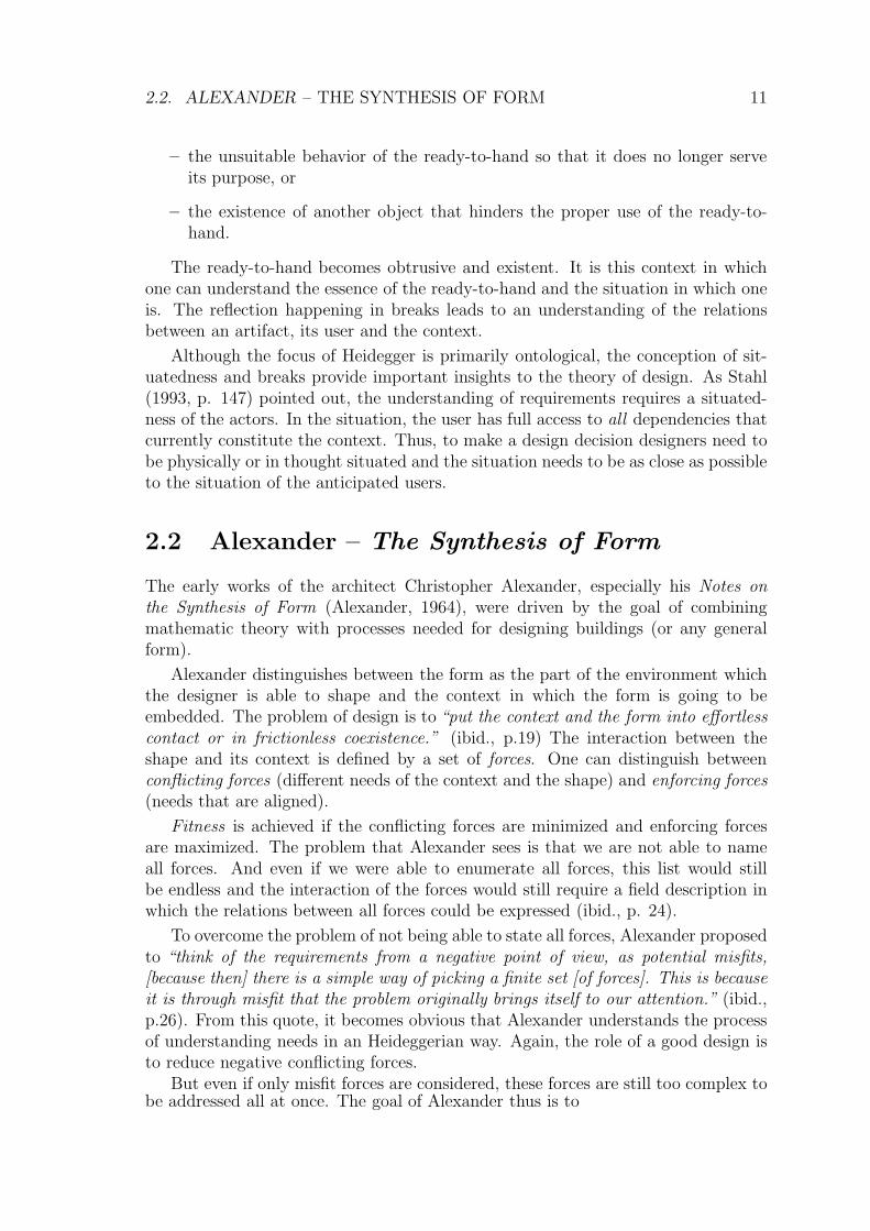
2.2 Alexander – The Synthesis of Form
The early works of the architect Christopher Alexander, especially his Notes onthe Synthesis of Form (Alexander, 1964), were driven by the goal of combiningmathematic theory with processes needed for designing buildings (or any generalform).
Alexander distinguishes between the form as the part of the environment whichthe designer is able to shape and the context in which the form is going to beembedded. The problem of design is to “put the context and the form into effortlesscontact or in frictionless coexistence.” (ibid., p.19) The interaction between theshape and its context is defined by a set of forces. One can distinguish betweenconflicting forces (different needs of the context and the shape) and enforcing forces(needs that are aligned).
Fitness is achieved if the conflicting forces are minimized and enforcing forcesare maximized. The problem that Alexander sees is that we are not able to nameall forces. And even if we were able to enumerate all forces, this list would stillbe endless and the interaction of the forces would still require a field description inwhich the relations between all forces could be expressed (ibid., p. 24).
To overcome the problem of not being able to state all forces, Alexander proposedto “think of the requirements from a negative point of view, as potential misfits,[because then] there is a simple way of picking a finite set [of forces]. This is becauseit is through misfit that the problem originally brings itself to our attention.” (ibid.,p.26). From this quote, it becomes obvious that Alexander understands the processof understanding needs in an Heideggerian way. Again, the role of a good design isto reduce negative conflicting forces.
But even if only misfit forces are considered, these forces are still too complex tobe addressed all at once. The goal of Alexander thus is to
12 CHAPTER 2. THEORY OF DEVELOPMENT ACTIVITIES
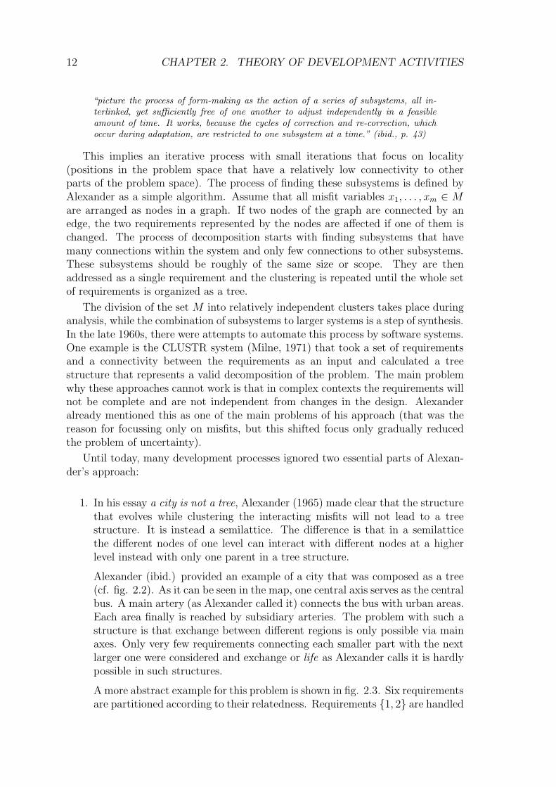
“picture the process of form-making as the action of a series of subsystems, all in-terlinked, yet sufficiently free of one another to adjust independently in a feasibleamount of time. It works, because the cycles of correction and re-correction, whichoccur during adaptation, are restricted to one subsystem at a time.” (ibid., p. 43)
This implies an iterative process with small iterations that focus on locality(positions in the problem space that have a relatively low connectivity to otherparts of the problem space). The process of finding these subsystems is defined byAlexander as a simple algorithm. Assume that all misfit variables x1, . . . , xm ∈ M
are arranged as nodes in a graph. If two nodes of the graph are connected by anedge, the two requirements represented by the nodes are affected if one of them ischanged. The process of decomposition starts with finding subsystems that havemany connections within the system and only few connections to other subsystems.These subsystems should be roughly of the same size or scope. They are thenaddressed as a single requirement and the clustering is repeated until the whole setof requirements is organized as a tree.
The division of the set M into relatively independent clusters takes place duringanalysis, while the combination of subsystems to larger systems is a step of synthesis.In the late 1960s, there were attempts to automate this process by software systems.One example is the CLUSTR system (Milne, 1971) that took a set of requirementsand a connectivity between the requirements as an input and calculated a treestructure that represents a valid decomposition of the problem. The main problemwhy these approaches cannot work is that in complex contexts the requirements willnot be complete and are not independent from changes in the design. Alexanderalready mentioned this as one of the main problems of his approach (that was thereason for focussing only on misfits, but this shifted focus only gradually reducedthe problem of uncertainty).
Until today, many development processes ignored two essential parts of Alexan-der’s approach:
1. In his essay a city is not a tree, Alexander (1965) made clear that the structurethat evolves while clustering the interacting misfits will not lead to a treestructure. It is instead a semilattice. The difference is that in a semilatticethe different nodes of one level can interact with different nodes at a higherlevel instead with only one parent in a tree structure.
Alexander (ibid.) provided an example of a city that was composed as a tree(cf. fig. 2.2). As it can be seen in the map, one central axis serves as the centralbus. A main artery (as Alexander called it) connects the bus with urban areas.Each area finally is reached by subsidiary arteries. The problem with such astructure is that exchange between different regions is only possible via mainaxes. Only very few requirements connecting each smaller part with the nextlarger one were considered and exchange or life as Alexander calls it is hardlypossible in such structures.
A more abstract example for this problem is shown in fig. 2.3. Six requirementsare partitioned according to their relatedness. Requirements {1, 2} are handled

2.2. ALEXANDER – THE SYNTHESIS OF FORM 13
Figure 2.2: The city of Brazilia (left) is composed as a tree (abstract version of a figure in
(Alexander, 1965)).
Figure 2.3: Decomposition using a tree structure (example from (Alexander, 1965)).
together and requirements {3, 4, 5} are also addressed in an isolated subsystem.The result of the latter set of requirements is combined with requirement 6and finally all subsystems are integrated. The advantage of this approachis that the interfaces between each pair of subsystems are very small. Thismakes composition easy. But this partition of requirements creates a solutionthat ignores many relations between the different subsystems (e.g. the relationbetween {3, 4, 5} and {1}. Exchange between the different subsystems is thusnot well supported.
If we compare the tree structure with the semilattice (as shown in fig. 2.4),we can see that the exchange between subsystems occurs to a larger degree.The structures overlap and thus reduce the frictions between the differentsubsystems.
2. Alexander did not intend that all requirements could be named a priori.
The latter issue has been further discussed by Rittel and Webber, who coinedthe term of wicked problems, which will be discussed in the next section.

14 CHAPTER 2. THEORY OF DEVELOPMENT ACTIVITIES
Figure 2.4: Decomposition using a semilattice structure (example from (Alexander, 1965)).
2.3 Rittel and Webber – Wicked Problems
Rittel and Webber (1973) termed the notion of wicked problems in design. Theirbasic assumption is that in such problems the requirements change whenever a designstep is performed. Since the design action itself changes the context of a problem,it is very likely that the context needs to be reanalyzed before applying the nextdesign step. During this analysis step, a new requirement may evolve, which can bestronger than the strongest requirement seen in the previous analysis phase.
Figure 2.5: Effects of a design step in a wicked problem.
Figure 2.5 shows this relation: If we consider an initial design in place, thisdesign interacts (in the notion of Heidegger) with its context. It is always situatedand the relations to the context can be analyzed and prioritized (shown as arrows infig. 2.5). The prioritization demands that a new part of the design is put into place(the black circle in fig. 2.5). But since this new design interacts with its context, itwill also change the context of the first design. Thus, the prioritization made withonly the first design in place will no longer be valid after adding the second design.
The problem definition in this sense co-evolves with the design. And each designstep will bring up new problems that need to be addressed. In theory, this wouldlead to an infinite set of design iterations and a monotonically increasing set of

2.4. SCHON – REFLECTION IN ACTION 15
relations of design with its context. For practical reasons, the cycles stop when aspecific quality threshold is reached.
Another important property of a wicked problem is that each instance of thisproblem is unique: since there cannot be two identical initial contexts (Heraclitusalready coined this insight with his quote παντα ρει – Everything flows, nothingstands still), the initial set of relations is always unique and thus no sequence ofdesign steps will be identical to other sequences (although different sequences maybe comparable).
Malotaux (2001) hit the point by identifying two requirement paradoxes:
1. Requirements should not change for reliable results, however the requirementsdo always change.
2. Developers don’t want requirements to change, however, since the risk ofchanging requirements is known, developers try to provoke requirements changein early phases of the project.
Fitzpatrick (1998) provided arguments why groupware design is a wicked prob-lem. She states that
The problem of how to understand what cooperative work means and how to designsystems to support that work is an inherently complex one that defies simple definitionsand solutions (ibid., p. 13).
The author is especially concerned about uncertainty regarding common solu-tions in the research community of CSCW and the variety of different experiencesdrawn from workplace studies. It is, according to Fitzpatrick, important to relateknowledge from an abstract level with knowledge from concrete instances.
Fitzpatrick criticizes that groupware design has so far often focussed on sup-porting one specific interaction (e.g. document co-authoring or decision making).These solutions, however, do not match with the wicked nature of group interaction.Instead, groupware design should focus on situated solutions that take an evolvinggroup context into account. Further on, Fitzpatrick argues that action-based ap-proaches that try to capture human interaction in pre-defined workflows are unsuit-able. Again the reason lies in the wicked nature of group interaction: when tryingto predefine a workflow, the context in which this workflow is applied (including allstakeholders current needs) may not change at runtime. When it changes, users willbe confronted with a break as Heidegger defined it.
2.4 Schon – Reflection in Action
An often used perspective on groupware design is influenced by the work of Schon(1983) who examined how professional users deal with break situations as definedby Heidegger. According to Schon, practitioners act using their implicit knowledgeof how to perform an action in response to challenges imposed by a specific context.Activities of this kind were referred to as knowing-in-action. Whenever the results
16 CHAPTER 2. THEORY OF DEVELOPMENT ACTIVITIES
of the action do not map to the intended results (i.e. the context does not behaveas anticipated), the practitioner lives through a breakdown (note that Schon uses adifferent term than Heidegger who uses the term break). Intuitive actions are nowsubject to reflection. The practitioner stops the action and to understand or reflectabout
(a) what he was trying to do (and thus makes the implicit knowledge about ac-tivities explicit), and
(b) what the forces are that prevent his intuitive actions to succeed. It is importantthat these forces are experienced at the time when the breakdown occurs sincethis supports a better understanding of the context that cannot be easilyanticipated in an unrelated design session.
Reflection opens new directions for action. In the context of tool design, thismay mean a new way of using the tool or a way of updating or tailoring the tool.The knowledge about the breakdown, its reasons (obtained through reflection), andits solution is kept as implicit knowledge by the practitioner.
Plan
DoStu-
dy
Act
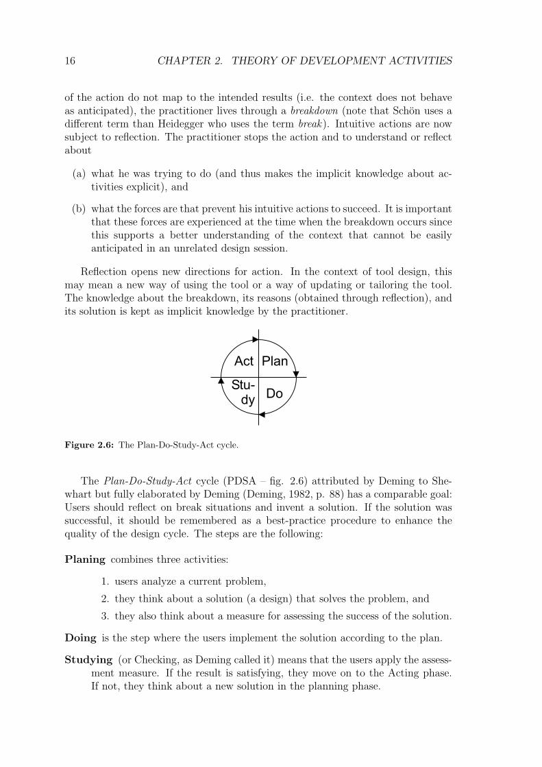
Figure 2.6: The Plan-Do-Study-Act cycle.
The Plan-Do-Study-Act cycle (PDSA – fig. 2.6) attributed by Deming to She-whart but fully elaborated by Deming (Deming, 1982, p. 88) has a comparable goal:Users should reflect on break situations and invent a solution. If the solution wassuccessful, it should be remembered as a best-practice procedure to enhance thequality of the design cycle. The steps are the following:
Planing combines three activities:
1. users analyze a current problem,
2. they think about a solution (a design) that solves the problem, and
3. they also think about a measure for assessing the success of the solution.
Doing is the step where the users implement the solution according to the plan.
Studying (or Checking, as Deming called it) means that the users apply the assess-ment measure. If the result is satisfying, they move on to the Acting phase.If not, they think about a new solution in the planning phase.

2.5. ALEXANDER – PATTERNS IN THE CONTEXT OF DESIGN 17
Acting helps to capture the solution. If the previous steps led to the desired success,the solution is used to change the standard procedures for action. Users learnthat the action was appropriate and add it to the canon of best practices.
Larman and Basili (2003) interpreted the PDSA cycle as the first occurrenceof iterative development and design. Since each iteration only addresses exactlyone problem, it creates a gradually improved catalogue of practices. Note that thedevelopment of software and especially of groupware applications is much closerto the application of PDSA to the manufacturing of an artifact since the createdsoftware is only built once and from then on copied without any additional effort.
2.5 Alexander – Patterns in the Context of De-
sign
In A city is not a tree, Alexander (1965) clarified that decomposition always needsto investigate the context of the unit of densely connected requirements. In Thetimeless way of building, Alexander (1979) proposed a new way of addressing con-nected requirements that puts an emphasis on the context of the problem – thepattern. Early forms of patterns were formulated as a mathematical description ofproblem spaces introduced in Alexander’s Notes on the Synthesis of Form. The firstreference can be found in (Alexander et al., 1968). In this publication, Alexanderdefined a pattern as a rule with two parts:
“the PATTERN statement itself, and a PROBLEM statement. The PATTERN state-ment is itself broken down into two further parts, an IF part, and a THEN part. Apattern reads like this:
IF: X THEN: Z / PROBLEM: Y
X defines a set of conditions.
Y defines some problem which is always likely to occur under the conditions X.
Z defines some abstract spatial relation which needs to be present under the conditionsX, in order to solve the problem Y.” (ibid., p. 15)
The patterns were organized in a semi-lattice structure (as discussed in section2.2) so that different levels of scale in the process of analysis could be reached. Allpatterns were organized in a pattern map shown in figure 2.7.
Later on, Alexander moved away from a strictly mathematical understanding ofpatterns. In A Timeless Way of Building, he defined it as a morphological law thatexplains how to design an artifact in order to solve a problem in a specific context.Patterns have several properties that inform design:
– They make the problem explicit instead of just stating a solution. The reader ofa pattern (ranging from lay persons to experts) is provided with a descriptionof the problem that helps him to compare the implicitly perceived problemwith other known problems.

18 CHAPTER 2. THEORY OF DEVELOPMENT ACTIVITIES
Figure 2.7: The pattern map shown in A Patten Language which Generates Multi-Service Centers
(APLMSC) (Alexander et al., 1968).
– They state the conflicting forces and explain how these forces change whenapplying the solution.
Alexander described the process of finding patterns in our environment:
”First define some physical feature of the place, which seems worth abstracting. ...Next, we must define the problem, or the field of forces which this pattern brings intobalance. ... Finally, we must define the range of contexts where this system of forcesexists and where this pattern of physical relationships will indeed actually bring it intobalance.”(Alexander, 1979, pp. 249, 251, and 252)
The resulting Alexandrian patterns as they were used in A Pattern Language(APL) (Alexander et al., 1977) are written in natural language and include thefollowing elements:
Name: Patterns start with a name that describes the solution. Examples in APLare Quiet Backs, Indoor Sunlight, or Sitting Circle.

2.5. ALEXANDER – PATTERNS IN THE CONTEXT OF DESIGN 19
Sensitizing photography: Under the name follows a photography of an environ-ment where the pattern is in place. The photography fulfills two purposes: (1)it gives the reader a first idea what the solution may look like, and (2) it helpsthe reader to better remember the pattern.
Context description: The context of a pattern is describing the space in whichthe pattern can be embedded. It often includes references to patterns on ahigher level of scale that have been considered before (the incoming edges infig. 2.7).
Problem statement: The problem statement marks the start of the pattern’sbody. It is first expressed in a short bold-faced paragraph and continuedwith the discussion of forces.
Discussion of forces: The discussion of forces helps the reader to better under-stand the problem and the relation to the context. In the Alexandrian patternformat, the forces are discussed and resolved in the text between the problemstatement and the solution statement.
Solution statement: The solution statement summarizes how the forces were re-solved in the forces discussion. Again, it is a short bold-faced paragraph.Together with the problem statement, it forms a thumbnail of the patternwhich already communicates the most important parts of the pattern. Thisallows readers to get a quick access to the pattern without reading too much.If the pattern looks relevant, a reader will read the forces section.
Diagram: In the context of architecture, patterns should, according to Alexander,be drawable. If the author is not able to draw a picture, then the describedsolution is no pattern. This extreme criteria for patterns is, however, notnecessary in other problem domains like social interaction patterns where thesolutions help to model dynamics.
Related patterns: The final part of the Alexandrian pattern format is the relatedpatterns section. It lists other patterns that are intended to be consideredtogether with the pattern. It often includes references to patterns on a lowerlevel of scale (the outgoing edges in fig. 2.7).
APL includes 253 patterns on different levels of scale. The patterns are highlyconnected, which reflects the interdependence of the addressed forces. While thepatterns in APLMSC could still be shown as an acyclic semi-lattice, the patternsof APL can no longer be arranged in an acyclic graph since they include 241 cycles(this may be the reason why Alexander no longer included overview diagrams).
2.5.1 Garfinkel – Ethnomethodology
Patterns play an important role in another field that is relevant to the field of de-sign and especially the field of requirements analysis: Ethnomethodology (Garfinkel,1967).

20 CHAPTER 2. THEORY OF DEVELOPMENT ACTIVITIES
Ethnomethodology provides an approach on understanding the ways how peopleinterpret their perception of the world. In short, the main idea is that all humaninteraction will be based on a categorization of phenomenons to existing under-standings of the world. If, e.g., one person communicates with another person, shetries to frame the utterances of her communication partner in the context of theconversation.
One illustrative example of Garfinkel (1967, p. 38) reports on the conversationof a couple and reveals how each utterance is subject to interpretation and how itis related to background knowledge:
Husband: Dana succeeded in putting a penny in a parking meter todaywithout being picked up.
To understand this utterance, one has to relate it to background knowledge thatis shared between the communication partners:
– The couple has a son called Dana who is 4 years old.
– The husband picked him up from kindergarten.
– After picking him up, they stopped somewhere since the son filled the parkingmeter.
– Normally the son needs to be picked up, but today he reached the parkingmeter on his own.
– This means that the son has grown or perfected his motoric capabilities.
Wife: Did you take him to the record store?
The wife has made the above interpretations and now wonders, where theystopped.
– She knew that her husband wanted to stop at the record store.
– The question is whether he was at the store before picking up his son or afterthat.
– If he was not stopping at the record store, the wife implicitly asks where elseher husband and her son stopped.
In the context of design, these implicit assumptions have to be communicatedbetween participants in the design process. But since one can never understandany communicative act without relating it to previous knowledge, there will be nocomplete record of assumptions. Therefore, the understanding of the requirementswill stay ambiguous. Two constructs help to reduce the ambiguity: users shouldbe as explicit as possible when reporting on requirements, and they should makeimplicit patterns of actions explicit.

2.6. ALEXANDER – THE OREGON EXPERIMENT 21
This is the part where patterns in the Alexandrian view come into play: Eachcommunication partner knows behavioral patterns that are followed by the othercommunication partner. In the above example, the wife knew that the son wasalways picked up to reach the parking meter. This was a practice that was commonto both wife and husband. However, the story becomes interesting since the patternis modified for the first time. The son no longer has to be picked up, which meansthat the wife can also change her repository of patterns.
Another implicit pattern is that the son normally gets picked up from kinder-garten. This is not mentioned in the conversation, but it is a daily recurring activitythat is common to both wife and husband. Patterns describe habits or rites that havebeen followed for a long time and that are common to a specific group or community.Making them explicit informs the design and the understanding of requirements.
2.6 Alexander – The Oregon Experiment
In 1980, Alexander explained how patterns should be applied and how they lead toa process of participatory design, the Oregon Experiment (Alexander et al., 1980).The foundation for this process lies in the philosophy of Alexander, which becomesclear in (Alexander, 1979):
“... people can shape buildings for themselves, and have done it for centuries, by usinglanguages which I call pattern languages. A pattern language gives each person whouses it, the power to create an infinite variety of new and unique buildings, just ashis ordinary language gives him the power to create an infinite variety of sentences.”(ibid., p. 167)
This vision was institutionalized in the planning process of the campus of theuniversity of Oregon (an updated version of the planning process that however stillincludes the basic principles outlined by Alexander is currently introduced – cf.(Ramey and Thompson, 2005)). The process defines six basic principles:
Participation ensures that the end-users will be part of the planning process and,therefore, participate in shaping their environments. Alexander defines par-ticipation on different levels, ranging from acting as a client for an architectto actually building their environment. ((Alexander et al., 1980), p. 39)
In the Oregon Experiment, participation led to a very successful campus de-sign. The university established a user group with students, faculty members,and staff. The user group decided, which projects should be built in the nextphases. In a refinement phase, special focus groups (users with specific inter-ests) concentrated on specific aspects of the building (focussing on one aspectat a time). In both, the user group and the focus groups, the prospective usersstarted thinking about the various aspects of the space and how each partshould be improved.
Coordination links together the different development initiatives made by theusers in the user group. This ensures that the design activities will stay coher-ent at the whole campus. Instruments to achieve coordination are a permanent

22 CHAPTER 2. THEORY OF DEVELOPMENT ACTIVITIES
planning office that coordinates the activities in the user group and brings dif-ferent users with overlapping plans in contact.
Organic Order turns out to be one of the most important principles although itdid not clearly emerge in the Oregon Experiment. For that reason, we will notdiscuss it now but postpone the discussion of organic order until section 2.8where this principle forms the basis of Alexander’s current design theory. Fornow, it is important that order defines a space in which the requirements ofthe users are satisfied and conflicts between users are minimized.
Piecemeal growth is the technique for reaching organic order. It argues to con-centrate on one aspect at a time. This includes identifying, and solving, oneconcrete problem.
Diagnosis and repair is the process of analyzing the existing campus regardingaspects that work, and aspects that do not work. This includes a phase ofreflection: during the use of the environment, users are encouraged to stepback and ask themselves, whether or not the environment serves their needs.If not, they are asked to mark the deficits and state change requests for theenvironment. The planning committee uses a map to catalogue all patternsthat are not working (and the places where patterns are working well).
The results of the reflection process are captured in a health map of the cam-pus. This health map shows areas of the environment that work well and areasthat need to be fixed (cf. fig. 2.8).
Patterns. To empower the end-users so that they can find working solutions, theynecessarily need a way of accessing established proven solutions. By means ofpatterns, one can describe expert knowledge as rules of thumb. These rulesinclude a problem description, which highlights a set of conflicting forces andmotivate a proven solution, which helps to resolve the forces.
In this manner, patterns can serve as an educational resource in the user group:they make the core of the problem and the solution explicit by explaining whathappens to the inner forces.
Additionally, patterns are the essential language applied in the user group:the patterns (taken from a pattern language (Alexander et al., 1977)) act asa basis to communicate on a high level of abstraction the key properties ofdesign.
Critics of the pattern approach have often argued that the pattern languagewould suggest an eternal truth. The style in which patterns are written (directimperative voice) emphasizes this impression. But if this would be the case,the patterns would have the quality of dogmas, which, in turn, would meanthat pattern authors describe unchangeable truth. In the Oregon Experiment,this impression is relativized (p. 137-141) by explicitly stating that patternlanguages should evolve:

2.6. ALEXANDER – THE OREGON EXPERIMENT 23
Figure 2.8: An example defect map of the University of Oregon (from
http://darkwing.uoregon.edu/∼uplan/graphic%20elements/album/NESummaryColor.gif).
– Participants should be encouraged to modify the published pattern lan-guage, which means that new patterns can be added and obsolete patternscan be removed.
– Patterns with an impact on the whole community have to be evaluatedand adopted by the whole community. This role can be delegated to aplanning board.
– In an annual review, the community checks the validity of all patterns.
– New or modified patterns can only be accepted on the basis of observa-tions or experiments.
As the culture of the community evolves, the pattern language that is used inthe community is intended to evolve as well. Alexander further argues thatall stakeholders should be encouraged to experiment with the patterns andpropose improvements. In the context of the Oregon Experiment, this affected,e.g., teaching staff or students. This means that not only the environmentof a user’s actions should be adapted, but also the ways of improving theenvironment should evolve.
All the mentioned principles are in use at the University of Oregon for nearly 30years. New patterns are still brought in by the users. For each new project, there is

24 CHAPTER 2. THEORY OF DEVELOPMENT ACTIVITIES
a user group that comes up with the requirements. Participation did not go as faras Alexander envisioned in the way that users draw schematic designs before hiringarchitects. Rather, they propose special patterns and design concepts as a basis forthe architects, who then continue the refinement together with the user group.
Another problem reported by the planning office was the application of piecemealgrowth. The main reason for this was that “all campus projects must go through theOregon State Legislature, which tends to favor larger building projects.” (Universityof Oregon Planning Office, 2005) Small projects in contrast receive fewer attentionby the institutions in charge of funding.
2.7 The Scandinavian Approach – Participatory
Design
End-user involvement is the main goal of participatory design (Schuler and Namioka,1993). It has its origins in the debate between Scandinavian industry and tradeunions regarding the relationship of work and democracy (Bjerknes and Bratteteig,1995). The goal was to amplify the user’s voice and thereby improve working life. In1977, this attitude was included in the Norwegian act relating to worker protectionand working environment (AML):
“The employees and their elected representatives shall be kept informed about thesystems employed for planning and carrying out the work, and about planned changesto such systems. They shall be given the training necessary to enable them to learnthese systems, and they shall take part in designing them.”
(Section 12, §3 of the AML (AML, 1977))
Bjerknes and Bratteteig (1995) provided three reasons, why participatory designwould lead to successful design decisions:
– Users who participate during the design process will help to improve the devel-opers’ knowledge about the system under development, and in turn the userswill gradually learn about the system that evolves. While the first aspect leadsto a system that is shaped to the users’ needs, the second aspect will ensurethat the users will be expert users of the system. The hope is that both aspectswill lead to a higher acceptance rate.
– Expectations of participating users will be in line with the system under de-velopment. This means that users will adapt their expectations during thedevelopment and reduce their resistance to change from a former context tothe new context imposed by the design.
– Workplace democracy is increased since the users who are affected by thesystem can influence the design decisions.
Bjerknes and Bratteteig (1995) identified four different levels of user participationaccording to the scope of the organizational unit in which design activities take place.
2.8. ALEXANDER – THE NATURE OF ORDER 25
– At the work situation level, users shape the tools that they need to performtheir work tasks. Cooperative design is one technique to reach participation atthis level. Users cooperate with designers and bring in their knowledge aboutthe specific tasks. This view on participatory design is related to the theoryof situatedness. Since the user is contributing experiences from the situation,the developed tool is likely to fit into comparable work situations.
– The workplace or organizational level focuses on interaction between users. Or-ganizational processes are shaped by the designed tools such as communicationtechnology. The socio-technical approach of design provides a background forparticipation at this level (e.g., Hirschheim et al., 1995, p. 36). It argues toaddress both organizational infrastructures and social systems found in orga-nizations. It has its roots in early action research projects of the TavistockInstitute with the focus on improving work conditions of British coal miners(in the year 1951). In the late 1960s and the early 1970s, tarde unions success-fully raised the awareness for a socio-technical view on organizational changes(cf. Mumford, 2000, for a history of socio-technical design). The main mes-sage was that social processes and technical systems that are involved in theprocesses should co-evolve. All members of the social system should have aninterest in improving the system and thus participate in its development.
– Design at an inter-organizational level shapes the relationship between theorganization and its context. The participation process is more difficult atthis level since the participants often can not be clearly identified. Theserelations have to be considered again from a socio-technical perspective.
– Finally, the social or working life level focuses on the work situation at thelevel of society. Factors that can be designed are, e.g., political constraints.Participation should be reached on a democratic basis.
In the context of groupware development, the workplace or organizational level isof special importance. End-users should be provided with social (process) structuresin which they can express their needs. One option is, e.g., user groups at theorganizational level that have to be consulted whenever the designed technology ismodified. In former times, this role was played by guilds, nowadays, e.g., workscommittees fill this role.
However, even though the end-users are in tight interaction with designers, thedesigners typically do all design activities. Participatory design stresses communi-cation with users throughout the design process, but assumes that the user can playthe role of skilled worker. Transfer of design knowledge to users was not in the mainfocus of participatory design.
2.8 Alexander – The Nature of Order
The most recent works of Alexander summarize the earlier approaches and describethe role of patterns and their application on a level that is no longer bound to

26 CHAPTER 2. THEORY OF DEVELOPMENT ACTIVITIES
architecture.
In The Nature of Order – The Phenomenon of Life, Alexander (2003a) intro-duced the concept of wholeness and the concept of centers.
Wholeness defines how well the different parts of a region in space interact. If aspace is whole, the different parts of the space help each other, instead of imposingconflicting requirements on the space. This definition of wholeness is in line withthe definition of (Smuts, 1936) who first defined it in the context of Holism. Holismdescribes the tendency in nature to form wholes that are greater than the sum ofthe parts. The parts and the whole co-evolve through creative evolution. Each partis connected to other parts by a field of forces. The more a part is embedded in thisfield of forces, the larger is its contribution to the wholeness of the organism.
Consider a social system as an example for the holistic perspective (cf. (Esfeld,2003)): Alice is a member of the social system. Alice in turn consists out of bonesand skin. But these components are no parts of the social system. In the contextof the social system, these parts are out of focus. What makes Alice a part of thesocial system is that she is capable of thought, action, and interaction with othermembers of the social system. These are the properties that constitute the socialsystem. Since Alice’s parts lack these properties, they are no longer consideredas being parts of the social system. Moreover, Alice can only interact with othermembers of the social system if she is situated in the social system. Therefore, thefull set of capabilities will only emerge if Alice is considered as part of a whole.
If the parts support each other, they evolve to centers. A center is a part inspace that is in relation to its context (and since the context is not restricted to thenearest points in space, it is in relation to all other centers). Centers may be strong,which means that they are in line with other centers that are close to them. Centerscan, however, only be understood in the context of the wholeness: since centersconstitute the whole, the whole shapes the view on centers. The whole evolves fromthe synthesis and interaction of its parts.
For Alexander, wholeness is always bound to spatial structures. Holism, in con-trast, is applicable to all structures regardless of any spatial properties. The onlyimportant property is that the structures carry a semantic distance. This is thereason why we consider the concept of wholeness applicable also for socio-technicalsystems (like groupware) as well. In socio-technical systems, the wholeness is com-posed of technical and social components (technical artifacts and users). And (asthe above example suggests) the nature of the components is defined by the contextof the socio-technical system. A user can, for example, play a specific role in a groupprocess. The role defines the users’ actions that shape the socio-technical system.At the same time, the role is defined by the socio-technical system.
Wholeness can now be defined as the strength of its contained centers and therelation of the centers. At the same time, the wholeness defines the centers. Centersalways become centers because of their position in the arrangement as a whole.
Transferred to the context of socio-technical systems, centers are structures thatsatisfy a specific requirement of the system. Relations between the different cen-ters map to the relation between different requirements. If two requirements are

2.8. ALEXANDER – THE NATURE OF ORDER 27
compatible (e.g., if one user of the system has the goal to teach another user andthe other user in turn has the goal to learn from the first user), then structures tosupport the requirements also support each other and thereby create strong centersand wholeness. On the other hand, if the requirements are conflicting, the structuressupporting the requirements will not support one another and can even destroy oneanother. In the first case, we speak of coherent requirements, while in the secondcase, the requirements are incoherent.
On a mathematical level, wholeness W can be defined as follows:
(1) Let S be a socio-technical system addressing n requirements R = {r1, ..., rn}.Represent a subsystem Sj of S by means of a bit vector j = j1, ..., jn withji = 1 if the requirement ri is considered as element of Sj , 0 otherwise (we willinterpret j as a binary number).
(2) Let cj be the coherence of the subregion Sj with 0 ≤ cj ≤ 1. Alexanderremarked that cj is a subjective measure. In our context of socio-technicalsystems, cj = 1 if and only if all requirements of Sj are satisfied and noneof the requirements are in conflict. Note that this is interesting only from atheoretic perspective since the behavior of human beings is non-deterministic,which makes it impossible to capture and satisfy all requirements for a socio-technical system (since these systems represent wicked problems). In realsocio-technical systems, cj will thus be smaller than 1.
(3) Call the subregions Sj with cj > t (with a given threshold t that is close to1) centers of S. Note that with a low value for t each single requirement ri
can represent a center although the individual value of cj (j ∈ 20,...,n−1) willbe quite low. In an hypothetic ideal case, the whole system S could emerge toa center. In this case, all requirements would be satisfied and emphasize oneanother.
(4) Then, the wholeness W is defined as the system S, together with the measurec and all those subregions that have a measure more than some threshold andthus qualify as centers.(cf. (Alexander, 2003a, p. 447))
The problem is to find a good measure c for part (2) of the definition. In TheTimeless Way of Building, Alexander (1979) called this measure the quality withouta name. This quality emerges if the interaction of forces can take place in theenvironment without conflicts.
In The Phenomenon of Life, Alexander proposed a more concrete definition bymeans of 15 fundamental properties that help the collection of centers to constitutethe whole. Examples in spatial systems are:
Levels of scale that help to perceive the center as part of a larger whole. Tostill perceive the coherence of the whole, the different levels of scale may notbe too different in scale.

28 CHAPTER 2. THEORY OF DEVELOPMENT ACTIVITIES
Strong centers that ask to look for the most important parts in the design.Alexander provided the example of a fire-place, which served as a strong centerin ancient buildings. It brings together the inhabitants since it is the center forvarious purposes: warming up, preparing food, telling stories, etc. In modernsocieties, it is much more difficult to identify strong functional centers.
Boundaries that help to better identify the center. It focuses attention on thebounded part and it situates the center in the context.
Deep interlock and ambiguity that argues to create centers that share partsof their surrounding. The intersections of the surroundings will form a newintermediate center that helps to strengthen the two original centers.
Contrast that stresses the need for differentiation. A center has to differentiateitself from the surrounding and from other centers.
Gradients that explains how centers with different goals can be connected. Thesolution is to establish intermediate centers that help to change one qualityslowly across space to another.
Simplicity and inner calm that argues to remove all centers that do not ac-tively support other centers. It could be considered as the demand for creatingthe simplest solution that could possibly work.
Not-separateness that reminds the designer to consider the designed artifact asa situated artifact. As in his earlier works, Alexander follows the Heiddegeriannotion of situatedness. The goal is to create a design that lacks abruptnessor sharpness. Such a design minimizes the probability of breaks that distractthe user of the space from his initial task. This is the reason why Alexanderconsidered this property as the most important of the 15 properties.
Other properties are Alternating Repetition, Positive Space, Good
Shape, Local Symmetries, Roughness, Echoes, and The Void. Alexan-der argues that the 15 properties constitute living structures in diverse sciences likearchitecture, biology, or physics.
Applied to socio-technical systems, these properties are still important. If weconsider again a group process, the above properties can be interpreted as follows:
Levels of scale affect the different levels of interaction ranging from single useractions (without considering other users) over small group interaction up tothe interaction in a large community.
Strong centers , for instance, can be kick-off meetings that are considered asimportant events by all group members.
Boundaries help to shield the group members from other group members and thussupport better interaction in the group.

2.8. ALEXANDER – THE NATURE OF ORDER 29
Deep interlock and ambiguity are omnipresent in group processes since groupmembers never belong to only one group. Instead, each person is a member ofmany groups in different social contexts.
Contrast can be observed when a group creates an identity that makes themdifferent to other groups.
Gradients are, e.g., important if group members gradually take responsibilities inthe group or build up trust.
Simplicity and inner calm argues, e.g., for group processes that reach the group’sgoal without much distraction.
Not-separateness reminds the group members that the group is again part of alarger social system and that the exchange with this system is important forthe group’s success.
In The Process of Creating Life, Alexander (2003b) discussed why design canlead to configurations with less or more wholeness. According to Alexander, the keyfactor lies in the process: If the process unfolds in a way that relevant centers areempowered and unimportant centers are reduced it is very likely that the resultingdesign creates a living structure.
Each modification of the designed space should focus on strengthening the whole-ness of the addressed subregion in space. And since the 15 properties contribute towholeness, each transformation should focus on making one or more of the propertiesstronger. Alexander calls these modifications structure preserving transformations.
He defines a process with the following steps
1. The process starts by paying attention to the current state of wholeness of afocal region R.
2. Then the weakest subregions are detected that lack wholeness.
3. These subregions are scanned for latent centers. One of these centers is thefocus of the next steps.
4. One or more of the 15 structure preserving transformations is applied to thelatent center.
5. This results in the strengthening of centers and the birth of new latent ormatured centers. Especially, larger existing centers should be strengthenedand the overall coherence of the region should be improved.
6. A first test checks whether or not centers really improved.
7. A second test checks if the improvement was the simplest solution that couldpossibly work.
8. If one of the two tests fails, the modification is undone.
30 CHAPTER 2. THEORY OF DEVELOPMENT ACTIVITIES
9. The process continues in a next cycle by looking at weak centers again.
Applied to a design task, the process creates a sequence of structure preservingtransformations. It is obvious that each step in such a sequence depends on thestep taken in the previous iteration. Having a sequence of n steps would lead to n!possible sequences, of which only a few are successful. This would not be feasibleif there were no aids in structuring the sequence so that it leads to a structurepreserving sequence.
The key factor here are patterns again. Considered in the context of wholeness,patterns are concrete instances of structure preserving transformations in a specificcontext. They describe how centers can emerge in a system of wholeness, andtherefore serve as generic centers. Their validity comes from empiric observations:If successful sequences applied these patterns, the probability that they will help tocreate a successful sequence in another project is high. Since it is possible to namethe effect on the different properties, it is also possible to approximate the effect oncj of a pattern (not in absolute values but in positive or negative tendencies).
From this perspective, patterns can be considered as strong generative rules thatplay a comparable role as memes do. Dawkins, who coined the term explained it asa replicator for ideas.
”Just as genes propagate themselves in the gene pool by leaping from body to bodyvia sperms or eggs, so memes propagate themselves in the meme pool by leaping frombrain to brain via a process which, in the broad sense, can be called imitation. Ifa scientist hears, or reads about, a good idea, he passed it on to his colleagues andstudents. He mentions it in his articles and his lectures. If the idea catches on, itcan be said to propagate itself, spreading from brain to brain. ” (Dawkins, 1989)
A meme, according to Gil-White (2005), carries several properties that allowthem to be part of a Darwinian process; namely inheritance, mutation, and selection.A meme is a representation of an idea that is passed on from mind to mind in ahuman culture.
Inheritance is bound to replication. Memes are passed on from brain to brain.Transferred to the idea of patterns, the patterns are best practices that are imitatedby other designers to create a good design. They are passed on from designer todesigner and experienced by the users (who again pass them on, though from adifferent perspective).
As Gil-White (2005) argues, memes mutate in every act of transmission, sincethey are combined with the receiver’s current set of memes (his mental state). Trans-ferred to the concept of patterns, a pattern is interpreted by the user who reads (orlearns) the pattern. This user combines the practices proposed in the pattern withhis own mental state, thus creating a mutated version of the pattern. This is whatAlexander described when he said that “each pattern describes a problem, in sucha way that you can use this solution a million times over, without ever doing it thesame way twice” (Alexander et al., 1977, p. x). It is thus not intended that each so-lution is an exact replication of the pattern. Instead, the solution has to have smalladaptations to the concrete context and the designer’s views (e.g., of aesthetics).But the adaptations should not be too large, otherwise the meme – or the pattern –

2.9. TAKEUCHI AND NONAKA – THE RUGBY APPROACH 31
would not survive; this means that it could no longer be identified and the problemaddressed by the meme would no longer be solved.
Whether or not a pattern survives depends on the probability that it will bepassed on. Strong patterns that generate strong centers are very likely to be passedon since they carry on a subset of the fundamental properties. Patterns with a largevalue for cj thus represent fit memes.
Gil-White (2005) pointed out that memes can only survive in the context ofother (supportive memes). He provided the example of the meme of Beethoven’sfifth symphone, which requires that the memes of playing musical instruments likethe violin or the trombone are passed on. The same is true for patterns. Theyrequire that supportive (and more widely accepted) patterns are passed on as well.The full set of required patterns then forms a pattern language.
Alexander proposes that each project constructs its own pattern language. Thislanguage can be invented from scratch (but still based on an empirical basis), com-posed from existing patten languages, or constructed by appropriating patterns tothe context of the project. It can even be valid to invent patterns without an empir-ical basis. In this case, the application of the patterns (in different sequences) hasto prove the validity of the patterns a posteriori.
The knowledge of pattern sequences helps to learn how to speak a pattern lan-guage. Compared to natural language, pattern sequences are examples of greatliterature that makes the best possible use of the language.
In summary, compared to The Timeless Way of Building and The Oregon Ex-periment, three aspects of patterns became more important: (1) the view of patternsas generic centers which means that they have to support the 15 properties, (2) theappropriation of patterns that reaches from the recomposition of a pattern languageup to the invention of new patterns, and (3) pattern sequences that steer a processof structure preserving transformations.
2.9 Takeuchi and Nonaka – The Rugby Approach
The question is how a holistic design can be supported by means of a design process.Alexander already provided the idea of structure-preserving transformation, but thisdoes not yet focus on group interaction in design. From Heidegger’s understandingof situatedness, the Oregon Experiment, and Schon’s concept of reflection in action,we highlighted the need for end-user involvement where end-users act as designersto shape their own environment. But still, the interaction in the team and thesequence of steps performed in the team (the workflows) need to be appropriatedfor innovative design.
Takeuchi and Nonaka (1986) use a sports metaphor for describing a creativeholistic design approach. They compare traditional design with a relay race: Con-crete responsibilities and tasks are assigned a priori to each team member. Thetasks are ordered in a sequence and each team-member depends on his predecessorcompleting his task. Communication between the team members is limited to the

32 CHAPTER 2. THEORY OF DEVELOPMENT ACTIVITIES
interfaces between the different tasks (e.g. passing a design document from a designgroup to an implementation group).
In contrast to this approach, Takeuchi and Nonaka propose a rugby approach: Ateam of players with different (multi-disciplinary) skills interact from the start to theend of the game. The ball is passed between team members frequently depending onthe current situation in design. Different activities take place simultaneously (e.g.the design evolves while at the same time, the implementation already investigatesthe applicability of earlier versions of the design). The goal however is to move thewhole team downfield.
The point is that this approach – although innovative and extremely flexible re-garding changing requirements – is vulnerable to wrong decisions. If, e.g., a require-ment was wrong, the initial design will have flaws, and a fixed requirement will causea re-design. But as we discussed in section 2.3, this problem is inherent to any de-velopment activity. Thus, facing it in a process of iterative experimentation showedto be appropriate in contexts addressing very wicked problems. Takeuchi and Non-aka provided case studies of innovative product development in larger multi-nationalcompanies, like IBM, Xerox, or Honda, to support their claim. They identified sixcharacteristics of these teams:
Built-in instability argues to intentionally state the problem as a wicked problemand thereby challenge creativity in the team.
Self-organizing project teams argue to give an interdisciplinary team the mostpossible freedom to act with a focus on in-team communication and exchangeof ideas and knowledge within the team.
Overlapping development phases describe the rhythm of activities within theteam in a way that different phases of development, like design and implemen-tation overlap to a large degree. The merits of such an approach are sharedresponsibility and cooperation in the whole team. Obvious problems includean increased need for communication; which may limit the application of thisapproach to projects with few members. In addition, overlapping phases re-duce the possibility of traditional division of labor for the benefit of sharedresponsibility.
Multilearning focuses on the importance at learning on different levels:
– the individual level on that a team member gains new insights regardinga task (e.g. by means of books),
– the group level on which the team performs learning as a group activity(e.g. by means of an excursion), and
– the corporate level (e.g., by means of a corporate education program inwhich all members learn a shared view on quality control).
Subtle control , where managers act like trainers of a rugby team. They selectthe players (and exchange them if appropriate), create a work environment,

2.10. GROUPWARE DEVELOPMENT REQUIREMENTS 33
establish training plans and reward schemes, or encourage the team to makemistakes and learn from mistakes.
Organizational transfer of learning that argues to propagate best practices ex-perienced in the development team to other teams.
2.10 Requirements for a Process that Supports
End-User Centered Groupware Development
In this chapter, we discussed different approaches to design. The discussion wasintentionally kept on a level that was not specific to software and groupware design.The reason for that was that the design of groupware needs to address the designof social processes as well as the design of technical support systems. A discussionof design methods needs to take into account that the design is not only targetedon creating technical solutions following a mechanistic view of design. Instead,situatedness and non-determinism of the users has to be taken into account.
describe solutions for a
set of forces
end-user involvement
social effects of design
iterative design
inform design
reflection
iterative design
concept of wholes
implementation affects
forces
Situatedness of users
who act as designers
interrelating forces
genetic evolution of
wholes by means of
patterns
evolution of ideas
diagnosis and repair
Holism - Smuts1926
Socio-Technical System -Trade Unions 1970s
Participatory Design -AML1977
Reflection in Action -Schøn1983
Nature of Order -Alexander2003
Patterns - Alexander1968
Situatedness -Heidegger1927
Darwinism and Evolution
Wicked Problems - Rittel &Webber 1973
PDSA - Shewhart 1939
Oregon Experiment -Alexander1980
Synthesis of Form -Alexander1964
Memes - Dawkins1976
Figure 2.9: Influences between the different approaches to design.
Figure 2.9 provides an overview of the relations between the different design

34 CHAPTER 2. THEORY OF DEVELOPMENT ACTIVITIES
theories discussed in this chapter. The different approaches to design suggest re-quirements for an ideal development process in order to solve the problem of thisthesis. The processes provided provided answers to the question why finding appro-priate requirements is a difficult task. Strategies that help to involve end-users areof special importance when designing a socio-technical system. The different designapproaches provided hints how the interaction between the user and the developmentteam may look like.
We will now summarize the requirements and relate the requirements to thedifferent design approaches.
The most comprehensive requirement defines that the resulting product shouldbe as good as possible. This may sound obvious, but in the context of the conceptof wholeness, it is a very concrete and difficult requirement to reach.3
R1: WholenessThe designed groupware system should have a high level of whole-ness.
We then derive requirements that describe how a high level of wholeness can bereached:
R2: Structure-Preserving TransformationsEach step performed in the design process should contribute to thegroupware’s wholeness.
Since resources are limited, designers and users should, preferably, perform thosesteps that lead to large positive changes in wholeness. This implies that the usersand developers are empowered to detect the most important issues at each step in theprocess. Due to the wickedness of the problem space, requirements analysis needsto take place as an integral part during the whole development. Three requirementssupport this goal:
R3: ReflectionThe process should encourage users to reflect on their activities andadapt their group environment so that the group task can be bettersupported.
R4: Process AwarenessUsers need to be aware of the current process and the current rank-ing of most urgent problems.
3Requirements will be references by their number throughout this thesis (e.g., R1). Refer tothe index for a mapping of requirement names and the pages on which the requirements wereaddressed.

2.10. GROUPWARE DEVELOPMENT REQUIREMENTS 35
R5: Iterative DesignThe process needs to support iterative extension and modificationof functionality in small iterations so that it can adapt to changinggroup processes.
Implicitly, the above requirements looked at the problem of finding the rightproblem to solve from two different perspectives: R3 put constraints on what prob-lem should be addressed while R5 demanded that not too many issues are addressedin one iteration. To be more concrete, we can even further restrict the size of itera-tions:
R6: One Problem at a TimeThe process should limit the development to one problem in eachiteration.
This does not mean that only one force can be addressed in isolation. Rather weconsider the problem space of groupware development as a highly related problemspace. Each solution should thus take the context of the problem and the solutioninto account.
R7: Field of ForcesEach problem and solution has to be investigated in its contexttaking the field of forces imposed by the context into account.
R8: Explicit ForcesDesigners and users should make these forces as explicit as possible.
The process of reflection already considers designers and end-users. Actually,both groups should participate during the whole life cycle of the application.
R9: End-User InvolvementEnd-users should be involved in the design process and find appro-priate interaction structures so that they can express their needs.
To play the role of an informed designer in the process of design, education is animportant prerequisite. The same is true for developers and designers (especially ifthey are new to the field of groupware development).
R10: EducationThe process needs means to make end-users and developers eloquentenough to express and exchange their personal needs, group needs,or design views.

36 CHAPTER 2. THEORY OF DEVELOPMENT ACTIVITIES
The latter requirement implies that end-users have to be empowered to un-derstand and assess the different design decisions in a way that the benefits anddrawbacks become clear to the user.
R11: Explicit ConsequencesSolutions should be stated in a way that the benefits and drawbacksof the solution become clear to the users.
Understanding the solution is the first step to successful reuse. To allow thedeveloper to apply the solution in his situation, he must be able to adapt the solutionto the context.
R12: IntegrationThe solutions should be adaptable to the socio-technical context likethe group structure, the programming language, the communicationprotocol, or the system environment.
R13: End-User DevelopmentWherever possible, users should be empowered to perform theseadaptations on their own.
Depending on the degree of adaptation, the applied solution can already be thesolution to a different problem. In this case, the solution should be fed back to thegroup so that future comparable problems can be solved more appropriate.
R14: Sharing of Best PracticesSuccessful adaptations and new designs have to be made availablefor all users so that they can be used for solving future problems.
R15: Quality ReviewThe quality of such new solution needs to be ensured by a soundreview process.
Table 2.2 shows how the requirements relate to the different theories of designdiscussed in this chapter. If an entry in table 2.2 is marked (M), it means that therequirements is also part of the corresponding design theory.
In the next section, we will review existing software and groupware design ap-proaches and show how they fulfill the requirements.

2.10. GROUPWARE DEVELOPMENT REQUIREMENTS 37
R1:
Whole
nes
s
R2:
Str
uct
ure
-Pre
s.Tra
nsf
orm
.
R3:
Refl
ection
R4:
Pro
cess
Aw
are
nes
s
R5:
Iter
ative
Des
ign
R6:
One
Pro
ble
mat
aT
ime
R7:
Fie
ldofForc
es
R8:
Explici
tForc
es
R9:
End-U
ser
Involv
emen
t
R10:
Educa
tion
R11:
Explici
tC
onse
quen
ces
R12:
Inte
gra
tion
R13:
End-U
ser
Dev
elopm
ent
R14:
Shari
ng
ofB
est
Pra
ctic
es
R15:
Quality
Rev
iew
Situatedness M M M M M M M M M
Synthesis of Form M M M M
A City is not a Tree M M M M
Wicked Problem M M
Reflection-in-Action M M M M M M M M
PDSA M M M M M M
Patterns M M M M M M M M
Gen. Centers & Memes M M M M
Oregon Experiment M M M M M M M M M M M M
Participatory Design M M M M
Holism & Wholeness M M M
Structure-Pres. Transf. M M M M M M M M
Rugby Approach M M M M M M M
Table 2.2: Relation between the different design approaches and the requirements.

38 CHAPTER 2. THEORY OF DEVELOPMENT ACTIVITIES

Chapter 3
State of the Art
We will address the state of the art in two phases: first, we will discuss existingsoftware development processes and techniques, and show how they relate to therequirements. We will, especially, discuss the impact that these methods have re-garding the understanding of wholeness. In a second phase, we will have a look athow these approaches have been applied in the context of groupware development.
3.1 Software Development Processes
In the last decades, many processes for the creation of software development haveraised attention. These reach from early life-cycle models (in times where a sequen-tial order of activities was the only dominant development method) up to iterativeand agile processes.
From the context of groupware development, it is important to understand upto what degree the different process models support the requirements elicitationin uncertain context of wicked groupware problems. Development processes can becategorized according to their level of evolution (ranging from non-iterative processesto processes with many short iterations – requested by R5) and their level of end-user involvement ranging from the involvement as a customer up to the involvementas a developer (R9 and R13).
As shown in fig. 3.1, current schools of software development can be classifiedas follows:
– sequential non-iterative processes that argue for a requirements definition onlyin early stages of the project (non-iterative, user acts as customer),
– iterative processes that are a sequence of instances of non-iterative processes(with varying iteration lengths in the different process models) (iterative, useracts as customer),
– agile methods that argue for close interaction and communication between end-users and developers in short iterations (very iterative, user acts as customerinteracting with the developer), and
39
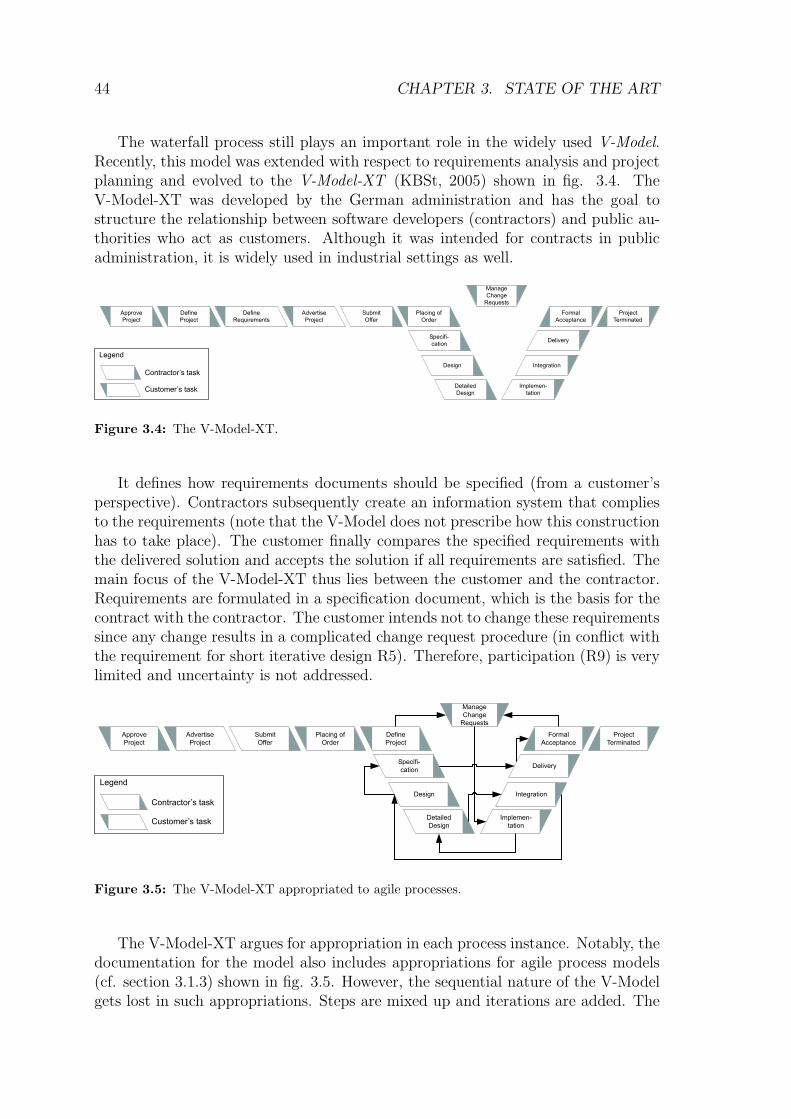
40 CHAPTER 3. STATE OF THE ART
Evolutionshort, e.g.,
weeklyiterations
some, e.g.,monthly
iterations
oneiteration End-User
Involvementuser ascustomer
user asdeveloper
agilemethods
sequen-tial pro-cesses
iterativepro-
cesses
end-userdevelop-
ment
participatorydesign
Figure 3.1: Classification of development processes with respect to their level of evolution and
their level of end-user involvement.
– participatory design and end-user development that focus on empowering theusers to act as designers or developers (iterative, user acts as designer or de-veloper).
In the next sections we will discuss representative development processes fromthese classes. The discussion will be complemented with additional techniques forrequirements elicitation and a view on how patterns have been utilized in the fieldof software development.
3.1.1 Sequential Non-Iterative Development
Alexander’s theory of decomposition was adapted by the software development com-munity leading back to the NATO conference on software engineering (Naur andRandell, 1968).
“... software designers are in a similar position to architects and civilengineers, particularly those concerned with the design of large hetero-geneous constructions, such as towns and industrial plants. It thereforeseems natural that we should turn to these subjects for ideas about howto attack the design problem. As one single example of such a sourceof ideas I would like to mention: Christopher Alexander: Notes on theSynthesis of Form.” (ibid., p. 35)
Later on in the conference, Naur suggested that the process of clustering require-ments and organizing them in a tree structure would be very promising to softwaredevelopment:
“... make a tree structure of the decisions, so that you start by consideringtogether those decisions that hang most closely together, and develop

3.1. SOFTWARE DEVELOPMENT PROCESSES 41
components that are sub-systems of your final design. Then you moveup one step and combine them into larger units, always based on insight,of some kind, as to which design decisions are related to one another andwhich ones are not strongly related.” (ibid., p. 45)
Top-down and bottom-up development , introduced in the early 1970s, followsthe same ideas: The set of functional requirements is refined and divided into (inde-pendent) sub-problems. The problems are translated into software when they canno longer be divided so that the individual parts would make sense in isolation.The parts are then combined (bottom-up) to larger structures until all requirementsare met. So, software engineering adapted the process for decomposing the prob-lem space into smaller, more feasible problems. The decomposition led – as Naursuggested – to a tree structure.
To this respect, the proposed decomposition shares all problems identified byAlexander in his essay A City is not a Tree. More specifically, the requirements maynot overlap, which, however, is often the case in reality.
Contemporary development concepts generate structures that often do no longercomply to trees: object-oriented systems, for instance, allow to model centers (ob-jects) and their relations to other centers (other objects). Different objects maycommunicate using message exchange. These messages can be exchanged concur-rently, which leads to a graph structure of interacting objects (with no restrictionsto the relations in the graph).
Therefore, decomposition can thus no longer be applied to the whole structureof a development project. Instead, its importance lies in contexts where one smallsub-problem is addressed for that the requirements are well defined and the focussedset of objects interact in a sequential order.
Fig. 3.2 shows the Waterfall process initially proposed by (Royce, 1970) whichis a prominent software development methodology that is based on decomposition.It arranges software projects in different phases. It starts with the design of therequirements, and, finally, reaches the operation of the implemented product. Theproblem with waterfall processes is that all requirements are collected at the be-ginning of the project and changes to the requirements should be avoided later on.According to Alexander this is a problematic understanding of design. Especially,it is in conflict with R5.
The original version of the waterfall process included two iterations: after thepreliminary program design a preliminary system should be built. This serves as aprototype for collecting first user experiences and assessing the technical behaviorof the system. The design of the preliminary system follows, again, a fully-fledgedwaterfall process except that it does not include a separate requirements analysissince the requirements were already gathered in the main waterfall process.
Royce intended that the customer is involved in four phases of the project: He (1)defines the requirements, (2) reviews the prototype built in the preliminary iteration,(3) performs critical software reviews between design and coding, and (4) performsan acceptance test before the system enters operation. The reason for includingthe end-user and for creating a prototype implementation was to reduce risk due to

42 CHAPTER 3. STATE OF THE ART
Analysis
Program
Design
Coding
Testing
Operations
System
Requirements
Software
Requirements
Preliminiary
Program
Design
Preliminary
Design
Analysis
Program
Design
Coding
Testing
Usage
System
Requirements
Generation
Preliminary
Software Review
Critical Software
ReviewCritical Software
ReviewCritical Software
ReviewCritical Software
Review
intended
sequenceFinal Acceptance
Review
End-User
Involvement
Development
Activity
failure
sequence
Figure 3.2: The Waterfall Process cf. (Royce, 1970)
vague or incorrect initial requirements. In relation to the requirements of section 2,it addresses the following requirements:
– R3 (Reflection) takes place when the user uses the preliminary system to gainusage experiences. The problem is that the usage of the preliminary system islimited to the time before the analysis phase of the main waterfall process.
– R4 (Process Awareness) is achieved since the process is formally structured.At each point in time, one can determine in which phase one currently is. Theproblem here is that the phases are very long and address different functionalaspects (e.g. all requirements have to be addressed in the design phase, whichmakes it difficult to determine what functional aspect is currently investigated,and how this aspect relates to other functional aspects).
– R5 (Iterative Design) is addressed by creating one prototype. However, thiscorresponds to exactly two iterations and these iterations do not detect therequirements independently. Since the number of iterations is fixed (and low),we cannot see R5 satisfied.
– R9 (End-User Involvement) takes place during reflection. However, the water-fall process rather speaks from customer involvement, which does not meanthe same: the customer does often not have to use the system in daily workcontexts.

3.1. SOFTWARE DEVELOPMENT PROCESSES 43
R1: Wholeness O R6: One Problem/Time O R11: Explicit Conseq.R2: Struct.-Pres. Trans. O R7: Field of Forces O R12: IntegrationR3: Reflection . R8: Explicit Forces R13: End-User Dev. O
R4: Process Awareness M R9: End-User Involvmt. . R14: Share Best Pract.R5: Iterative Design . R10: Education R15: Quality Review
Table 3.1: Relation between the waterfall process and the requirements.
The waterfall process was widely cited. Notably, most citing authors reducedit to a linear sequence from analysis to design that did not include the preliminarysystem development and the steering points for the end-user (e.g. (Davis, 1997)or (Malotaux, 2001)). This has the effect that most “waterfall” projects do notaddress the requirements R3, R5, and R9. Large projects especially often rely onformal requirements that are defined before developing the system and that serve asa contract between customer and the development team.
requirements
analysis
design
coding and
unit test
system
integration
operation &
maintenance
cost ofchange
stage in the process
Figure 3.3: Cost of change from a waterfall process perspective (adapted from Beck (1999, p.
21) and Kruchten (2003, p. 13)).
The reason for this is to reduce the cost of change since many developers assumethat changing requirements become more expensive the later they are detected in thedevelopment process as shown in fig. 3.3 (cf. also the second requirement paradoxin section 2.3).
Table 3.1 summarizes the requirements addressed by the waterfall process.1
1If a requirement is violated, the table includes a O, if it is partially addressed, it shows a .,and if it is supported, it shows a M. In cases where the process supports a requirements very well,N is shown. Note that in this and the following sections only requirements that are addressed orexplicitly hurt by the process are mentioned. Requirements that are not applicable will not bementioned in the discussion. The cell in the table will stay empty in this case. A comparison ofthe different process models discussed in this chapter can be found on page 77.

44 CHAPTER 3. STATE OF THE ART
The waterfall process still plays an important role in the widely used V-Model.Recently, this model was extended with respect to requirements analysis and projectplanning and evolved to the V-Model-XT (KBSt, 2005) shown in fig. 3.4. TheV-Model-XT was developed by the German administration and has the goal tostructure the relationship between software developers (contractors) and public au-thorities who act as customers. Although it was intended for contracts in publicadministration, it is widely used in industrial settings as well.
Formal
Acceptance
Delivery
Integration
Implemen-
tation
Detailed
Design
Design
Specifi-
cation
Placing of
Order
Project
Terminated
Submit
Offer
Advertise
Project
Manage
Change
Requests
Define
Requirements
Define
Project
Approve
Project
Legend
Contractor’s task
Customer’s task
Figure 3.4: The V-Model-XT.
It defines how requirements documents should be specified (from a customer’sperspective). Contractors subsequently create an information system that compliesto the requirements (note that the V-Model does not prescribe how this constructionhas to take place). The customer finally compares the specified requirements withthe delivered solution and accepts the solution if all requirements are satisfied. Themain focus of the V-Model-XT thus lies between the customer and the contractor.Requirements are formulated in a specification document, which is the basis for thecontract with the contractor. The customer intends not to change these requirementssince any change results in a complicated change request procedure (in conflict withthe requirement for short iterative design R5). Therefore, participation (R9) is verylimited and uncertainty is not addressed.
Formal
Acceptance
Delivery
Integration
Implemen-
tation
Detailed
Design
Design
Specifi-
cation
Project
Terminated
Submit
Offer
Advertise
Project
Manage
Change
Requests
Approve
Project
Legend
Contractor’s task
Customer’s task
Define
Project
Placing of
Order
Figure 3.5: The V-Model-XT appropriated to agile processes.
The V-Model-XT argues for appropriation in each process instance. Notably, thedocumentation for the model also includes appropriations for agile process models(cf. section 3.1.3) shown in fig. 3.5. However, the sequential nature of the V-Modelgets lost in such appropriations. Steps are mixed up and iterations are added. The

3.1. SOFTWARE DEVELOPMENT PROCESSES 45
fact that such appropriations can be found in the official V-Model documentationshows that a linear sequence of steps is often not appropriate in real-world develop-ment projects.
But, as discussed in section 2.3, the design of software and especially the designof groupware often leads to changes in the requirements. This means that a projectthat follows a single waterfall process can easily fail. The question thus is how to“embrace change” (Beck, 1999). Iterative software development processes provide asolution to this problem.
3.1.2 Iterative Development Processes
The basic idea of iterative software development processes is to reduce the lengthof the process and perform the process multiple times. According to Larman andBasili (2003), it has its roots in early development project at IBM in 1957. In 1985,it was made more prominent with Boehm’s introduction of the spiral developmentprocess framework (Boehm, 1988). One prominent example of contemporary itera-tive processes is the Rational Unified Process (RUP) (Jacobson et al., 1999). Theiterations in RUP can be compared with small Waterfall processes (including thefull set of documents that is normally produced in a waterfall process).
require-
ments
analysis
design
implemen-
tation and
test
require-
ments
analysis
design
implemen-
tation and
test
require-
ments
analysis
design
implemen-
tation and
test
require-
ments
analysis
design
implemen-
tation and
test
Iteration 0 Iteration 2Iteration 1 Iteration n...
Figure 3.6: Connecting multiple instances of a waterfall process to reach an iterative process.
Although the RUP was not the first iterative process in the context of softwaredevelopment it received much attention. Key concepts are, compared to the water-fall process, much shorter iterations and explicit roles and workflows for activitiesperformed in the development team (cf. fig. 3.7).
According to the progress in the project the different iterations will have a dif-ferent composition regarding the importance of the individual phases: the inceptionphase, the elaboration phase, the construction phase, and the transition phase. Theinception phase mainly focuses on requirements elicitation and the definition of theoverall idea of the project. The elaboration phase focuses on making the use-casesmore concrete. It includes parts where first ideas are implemented in a prototypesystem. The construction phase focuses on the implementation of the system. Re-quirements, analysis, and design are still part of each iteration in the constructionphase, but their impact on the implementation task will not be as large as in previousphases. This means that most of the time is spent in implementation.

46 CHAPTER 3. STATE OF THE ART
System
Analyst
Find Actors
and
Use Cases
Structure the
Use-Case
Model
Use-Case
Specifier
Detail a
Use-Case
User-
Interface
Designer
Prototype User-
Interface
Architect
Prioritize Use-
Cases
Architectural
Aalysis
Architectural
Design
Architectural
Implementation
Use-Case
Engineer
Analyze a
Use-Case
Design a
Use-Case
Component
Engineer
Analyze a
Class
Design a
Class
Analyze a
Package
Design a
Subsystem Implement a
Subsystem
Implement a
Class
Perform a
Unit-Test
Implement
Test
System
Integrator
Perform
Integration Test
System
Tester
Perform
System Test
Integration
Tester
Perform
Integration Test
Test
Engineer
Evaluate TestDesign TestPlan Test
Requirements
Test
Implementation
Design
Analysis
Figure 3.7: Roles and workflows in the first edition of RUP (ibid, p. 324).
In later editions of the RUP (Kruchten, 2003), the development centered viewwas complemented with additional supportive workflows for the management. Theseare:
Deployment focusing on creating a system that can be passed on to the customer(including the required documents).
Configuration- & Change-Management that provides workflows for managingchange requests and configuring the different versions of the product.
Project Management focussing, e.g., on risk assessment, the definition of productmeasures, or the management of the team’s work schedule.
Environment with the goal of equipping the development team with the right tools(e.g., software development environments).

3.1. SOFTWARE DEVELOPMENT PROCESSES 47
Deployment becomes important in late stages of the construction phase.Configuration- and Change-Management is an important issue throughout the con-struction phase. The transition phase concentrates on shipping the project, andinstalling it at the client’s site. In this phase, deployment, configuration manage-ment, change management, and the implementation of required changes are in themain focus.
The core process model focuses on the management of and the interaction inthe development team. One role, the system analyst, is supposed to interact withthe customer. But the customer is still in a position where he states requirementsand tries to limit the interaction with the development team afterwards. Unless thecustomer takes one of the roles defined in the workflows (and thus acts as a memberof the development team) his influence will be limited.2 The focus on formal changerequest procedures in addition slows down the reaction to change of the context.
Ambler et al. (2005) extended the RUP with workflows for later phases in theproduct life-cycle – the production phase and the retirement phase – and called thisextended process the Enterprize Unified Process (EUP) (see also Ambler, 2005b).
Business Modelling
Requirements
Analysis & Design
Implementation
Test
Deployment
Configuration- & Change-Mgmt.
Project Management
Environment
Operation & Support
Inception Elaboration Construction Transition Production Retirement
Iteration
Figure 3.8: Importance of disciplines in different phases of the EUP (cf. Ambler, 2005b).
The production phase provides guidance on keeping the product running. Thus,“operations and support” play an important role as additional discipline. Change-and configuration management additionally focus on registering user change requestsand scheduling these requests for a future redesign of the system. In the productionphase, only minor bug-fixes are performed, which implies that major change requestsfrom a user will have to wait for a new project.
The retirement phase describes how the system should be replaced by anothersystem or removed. Change and configuration management is extremely importantin this phase.
2Ambler (2005a) argues that the customer should be trained to fill roles such as the BusinessProcess Designer and Requirements Specifier. This, however, requires that the customer movesaway from his original profession towards an analyst’s profession.

48 CHAPTER 3. STATE OF THE ART
R1: Wholeness O R6: One Problem/Time O R11: Explicit Conseq.R2: Struct.-Pres. Trans. O R7: Field of Forces O R12: IntegrationR3: Reflection . R8: Explicit Forces . R13: End-User Dev. O
R4: Process Awareness M R9: End-User Involvmt. . R14: Share Best Pract.R5: Iterative Design M R10: Education R15: Quality Review
Table 3.2: Relation between the Unified Process and the requirements.
Fig. 3.8 shows the importance of the different disciplines in the context of thelife cycle.
The EUP (as a more comprehensive version of the RUP) better meets the re-quirement of iterative design that we expressed in R5. Compared to the waterfallprocess there are many iterations and the iteration length is reduced. The overheadof documentation and formal activities is also reduced since EUP asks developers tofocus only on documents that make sense during a specific iteration. Nevertheless,it is still a document-centered approach in which communication is structured bymeans of pre-structured documents (e.g. class diagrams, formal use cases, or inter-action diagrams (Fowler, 2000)). All participants have to learn to understand andwrite such documents, which makes it hard for end-users to participate in the designand implementation phases.
For each iteration the developers perform an iteration planning. This includesthat the tasks for the current iteration are defined. Process awareness (R4) is thusestablished, although an iteration focuses on a set of problems rather than on onesingle problem (in conflict with R6).
The involvement of end-users is coordinated by the system analyst in the earlyanalysis phases. He interacts with the customer and creates use cases. Use casesre formal scenarios of system use. Unlike user stories, they follow a predefinedstructure with the goal of describing the system behavior as exact as possible.3 Inthe production phase, the customer has two interaction partners in the developmentteam: the customer service representative is responsible for communicating with theend-users and assisting them during system use. “Problems” that have their originsin the user’s “misunderstanding” of the system are solved by the customer servicerepresentative since he helps the users to learn how to use the system. The systemsupport representative is responsible for cases where the system misbehaves. Heescalates these defects or enhancement requests to the actors in the configurationand change management discipline so that they can be scheduled for a future release.Other involvement requires, as discussed above, that the user becomes an analystor a developer. This is why end-user involvement (R9) is still limited, especially inthe context of system use, where the user should be encouraged to reflect (R3). Theprocess does not further guide how the users should be educated to act as designers(R10) or even perform changes on their own (R13).
Table 3.2 summarizes the requirements addressed by the Unified Process.
3Note that Cockburn (2000) proposed a more prosaic notion for use cases that is very suitablefor end-user involovement.

3.1. SOFTWARE DEVELOPMENT PROCESSES 49
A tighter integration of the customer during all phases is desirable for groupwareapplication development. Agile methods that will be discussed in the next sectionaddress this problem.
3.1.3 Agile Methods for Software Development
Agile software development (e.g. Cockburn, 2002) focuses on tighter interactionwithin the development team and between the team and the customer. At thesame time, it argues to reduce the creation of artifacts used in a process and thenumber of formal workflows of the process. This is expressed by the Agile Manifesto:
“We are uncovering better ways of developing software by doing it and helping othersdo it. Through this work we have come to value:
– Individuals and interactions over processes and tools
– Working software over comprehensive documentation
– Customer collaboration over contract negotiation
– Responding to change over following a plan
That is, while there is value in the items on the right, we value the items on the left
more.” (Beck et al., 2001, original emphasis)
The motivation for agile methods is that the requirements will change over theproject life cycle. Instead of minimizing risk through more elaborated analysis anddesign (before doing any development), it focuses on creating simple solutions thatare easy to modify and adapt to changed requirements. If the software is kept simple,the exponential cost of change (fig. 3.3, p. 43) will be reduced so that it is no longerexponential (fig. 3.9).
cost ofchange
stage in the process
Figure 3.9: Cost of change from an agile process perspective (adapted from Beck (1999, p. 23)).
A large set of agile methods has evolved since the mid 1990s.4 These methodscan be understood as templates for concrete processes that are tailored to a specific
4Refer to Abrahamsson et al. (2003) or Boehm and Turner (2004) for an overview, a genealogy,and a comparison of current agile methods.

50 CHAPTER 3. STATE OF THE ART
project (since the agile manifesto explicitly states that the focus should be on theindividuals that are participating in the process, rather than on the process itself).
Agile methods have been perceived quite controversial, since they argue to travelwith as few as possible formal workflows and documents. Tom Demarco, e.g., ex-pressed his preference for agile methods in a personal communication with GradyBooch as follows (Booch, 2001, footnotes not part of the origional quote):
“I think the strongest trend at work today is toward light methodology. In this
class I include Booch Lite5, Kent Beck’s XP6, Scrum7, DSDM8, Crystal Methods9
(by Alistair Cockburn), and Jim Highsmith’s Adaptive Development.10 Probably the
most prominent of these is XP (extreme programming). It is the best of a new breed of
approaches that thumb their noses at CMM11 and all other forms of fundamentalism.
The focus has to be on building skills into the people, not building regimentation into
the process. It requires no great leap of intellect to see that everything has to go faster
in this age. You don’t go faster with bigger methodology; to get faster we have to
move toward much lighter methodology. The CMM makes us wonder What else shall
we add? while the light methodologists are always asking What can we take away?”
The main argument against agile methods is the lack of empirical evidence.Instead of being synthesized using scientific measures and tools, most of the methodshave evolved from subjective personal experience. However, the body of empiricalscientific evidence is currently growing for all agile methods (cf. Abrahamsson et al.(2003) for a list of recent studies and (Cohen et al., 2003) for an overview of currentagile methods). The results of such studies help to point out the advantages andthe limitations of agile approaches.12
In the following section, we will discuss three agile methods regarding their ap-propriateness for groupware development. We selected (1) eXtreme Programming
5Booch (1992)6See page 51.7See page 55.8Dynamic Systems Development Method (DSDM Consortium, 1997) is a development method
organized in five phases comparable to the RUP. It emphasizes activities related to project man-agement, especially methods for prioritizing requirements. Customers classify the requiremnts infour distinct categories (Must have, Should have, Could have, and Want). As in the RUP, thestrong focus ion planning should help to reduce risk.
9The Crystal Methods define a process framework for development processes that focus oncommunication and people (Cockburn, 2002). It is intended that the methods are tuned to matchthe organizational context and the concrete problem.
10Adaptive Software Development (Highsmith, 2000) – a process model that argues for a highlevel of flexibility in the team so that it constantly adapts plans and actions to the current situation.
11CMM (or the most recent version CMMI – (CMMI Product Team, 2002)) is a framework forevaluating the maturity of a software process. It describes on more than 700 pages requirements fora software process and the documents that need to be created in the process. Together with Boehmand Turner (2004, p. 187), we consider the CMM as a framework that generates heavyweightprocesses.
12It is needless to say that the same evidence is still needed for newer methods that are basedon more traditional approaches (like the EUP). Thus, we observe a problem of credibility for mostnew development process models.

3.1. SOFTWARE DEVELOPMENT PROCESSES 51
(XP) since it is the most widely known agile methodology, (2) Scrum since it isrelated to Rittel’s concepts of wicked problems and based on Takeuchi’s and Non-aka’s rugby approach, and (3) Feature-Driven Development that is closely relatedto UML-based approaches like the RUP and thus bridges the gap between agile andtraditional approaches.
eXtreme Programming
eXtreme Programming (XP) was disseminated to a broad public with the publicationof Beck (1999). It is based on four values that should shape development activities:
1. Communication that argues for as much face-to-face communication as possi-ble and needed to achieve a shared understanding in the team and between theteam and the (on-site) customer. Communication is the most important value.Since the teams often create software without having a formal (specified) de-sign, it is much more important that an agreement in the team about technicalsolutions is reached and that this agreement is communicated to other teammembers.
2. Simplicity, so that only the simplest solution that could possibly work is de-veloped. This value is based on the observation that in traditional processesmany features or extension points are built but never used.
3. Feedback, so that all participants always have an impression about the currentstate of development.
4. Courage that demands of all participants to accept failure and fix it (ratherthan creating work-arounds) or to throw code away if it shows to be insufficient.
The principles match with the values of the agile manifesto. Communication sup-ports interaction and customer collaboration. Simplicity supports working software(the system does exactly what users want and not more). Feedback and couragesupport responsiveness to changes.
From the core values, Beck derived 12 practices that should be applied in a XPproject (cf. fig. 3.10). Coding standards, collective ownership, pair programming,and the 40 hour week are very specific to the activities of the developers (the pro-grammers) in the team. The other practices are more important with respect to therequirements of chapter 2.
Testing using a test-first approach and refactoring describe a process comparableto diagnosis and repair of the Oregon Experiment (cf. p. 22). Before any modifi-cation is applied to the system, developers and users are asked to think about teststhat check the system for the break that should be fixed (reflection – R3). This testshould describe the conflicting forces and how these forces should be resolved by thesystem. After the test is written, the developers and users check whether the testreally fails (to “show” that the test is correct). They then implement a solution thatresolves the conflicting forces (and thus satisfies the requirements). After the solu-tion is built the system is checked again to prove that the modification really solved

52 CHAPTER 3. STATE OF THE ART
On-Site Customer
Simple Design
Metaphor
Short Releases
Coding Standards
Collective Ownership
Testing
Refactoring
Continuous Integration
Planning Game
40 Hour Week
Pair Programming
Diagnosis& Repair
End-UserInvolvementOne Problem
at a Time
Figure 3.10: Practices in XP in relation to requirements for a groupware development process
(adapted from Beck (1999, p.70))
the problem. To check whether or not all other forces are still resolved according tothe users’ needs these tests are collected and re-executed when integrating the solu-tion with the whole system. This ensures that the system continuously evolves andthat existing centers are improved (supporting structure-preserving transformations– R2).
Refactoring implements diagnosis and repair on a non-functional level. In testfirst design, the users reflect and report on break situations. In refactoring, devel-opers report on breaks from a technical perspective – so-called code-smells. At thislevel, a break is produced by code that is hard to understand. Whenever developersencounter such code that smells, they are asked to refactor the code using a trans-formation guideline (the refactoring) from a refactoring catalogue (Fowler, 1999).Each refactoring is a micro-pattern that describes how to detect bad code and howto transform it in order to make it more readable and flexible for future extensions.
Simple design supports both refactoring and test first development. The ideabehind this practice is that code is designed without any unneeded structures andthat the designed artifact has a good shape. With this respect, simple design can beseen as a practice that helps to bring the properties Simplicity and Inner Calm
and Good Shape into place (cf. section 2.8).
To create good shape, developers and end-users need to establish a shared visionof the built system. They need an idea of the shape, comparable to a sculptorwho needs a vision in order to transform a stone into a sculpture. Finding andcommunicating such an idea can be a challenging problem in XP.

3.1. SOFTWARE DEVELOPMENT PROCESSES 53
Beringer (2004) describes the problem in the interaction between developers andend-users as expertise tension: End-users may lack the expertise needed to build,appropriate, or apply tools in a specific context. Among others, one approach toovercome this problem is the use of metaphors to map problems of an unfamiliardomain to a more familiar problem space. According to Lakoff (1993), there areseveral aspects that define a metaphor:
– Metaphors serve as mappings across conceptual domains.
– Metaphors serve as conceptual means not as linguistic constructs.
– Metaphors are asymmetric and partial, which means that only important partsof the source domain are captured by the metaphor and projected to the targetdomain.
– The mapping works by focussing on correspondence in experiences connectedto the entities in a source domain and entities in a target domain.
– The correspondences help to apply patterns of use that are familiar in thesource domain to the target domain.
From this background, the process of software development can be understoodas the process of creating metaphors. Patterns of use from a familiar domain have tobe mapped to another domain (with a potentially different context). The softwaredeveloper helps to find or invent metaphors while communicating with the end-user. The problem is that good metaphors are hard to find and that XP doesnot provide guidance in this search process.13 Good patterns (that describe strongcenters), however, could fill the role of a system metaphor in XP (more details onthis thought will be discussed in section 4).
The second shaded area in the upper part of fig. 3.10 contains practices that arerelevant for involving the end-user and addressing his needs.
End-user involvement is one of the most important but also most difficult is-sues in XP (R9). XP argues that a customer representative should live with thedevelopment team as an on-site customer. It mainly focuses on participation duringrequirements engineering related tasks. The user acts as a member of the develop-ment team and steers all activities. The advantage of an on-site customer is thatthere is always a person at hand, who has experienced the requirements and can pro-vide more detail on the requirements whenever needed (cf. (Paetsch et al., 2003) fora deeper discussion of requirements engineering in agile processes). The customer’sspecial focus is on the planning game. The planning game is a lightweight tool forrequirements elicitation and prioritization. The users create stories that describe the
13Khaled et al. (2005) wrote a pattern language to support the detection of a metaphor inXP. Their guidance is to examine the semantic network addressed by the system in a so-calledmetaphorscape. Areas of special focus are then identified in the metaphorscape. the most impor-tant metaphors are further investigated in a group inspection with the goal of identifying good andweak points of the metaphor.

54 CHAPTER 3. STATE OF THE ART
system behavior (informal success stories comparable to those described by Cock-burn (2000)). In addition, the users think of a test that would convince them toaccept the solution (the acceptance test). The stories are collected on story cardsand estimated regarding the required efforts to implement each story estimated byall members of the planning game.
In a next step, the customer “shops” user stories until the available resources ofone release are spent. He also prioritizes the “bought” stories since it is a rule ofXP that estimates can be wrong. The result of the planning game is an orderedlist of story cards that will be implemented in that order (and thus supports a goodprocess awareness – R4).
Note that the customer can change his mind, which results in new stories, re-moved stories, or a new order for the stories. This requires that the stories aresmall. One iteration (lasting one or two weeks) should provide enough resourcesfor addressing several stories. It also requires that the customer accepts to take re-sponsibility for the implemented system. Small releases and continuous integrationhelp the customer to reduce risk, since he always has a working piece of software. Apredefined requirements specification that serves as a contract is, on the other hand,not applicable for XP projects.
Instead, time boxing is more appropriate (Malotaux, 2001). This approach de-scribes a situation where time and costs are fixed. In the three-dimensional processof design that considers time, costs, and features, features are the only variant toreact to changes in the plan (cf. fig. 3.11).14
Time Costs
Features
Figure 3.11: The set of features varies during the development process (adapted from Malotaux
(2001))
One often neglected point in the planning game is that the customer needs tobe able to create stories. As we discussed it chapter 2, this is difficult for wickedproblems without any additional guidance regarding orientation in and identifica-tion of the problem space. The process of reflecting and determining conflictingrequirements is difficult and not supported in XP’s core process model. Hazzan andTomayko (2003) proposed to combine interaction of the planning game with Schon’sconcept of reflection in action (to satisfy R3). Discussions in the planning games
14Note that Beck and Fowler (2001) add a fourth value, quality, that should also be fixed.

3.1. SOFTWARE DEVELOPMENT PROCESSES 55
should be structured in a way that the customer moves through different levels ofreflection (cf. ibid.):
– Designing: The customer feels the need of a requirement and is asked to thinkabout comparable situations he experienced before.
– Description of designing: The customer identifies comparable problems andreshapes the design ideas of the first step by applying lessons learned from thecomparable design problem.
– Reflection on description of designing: The developer reflects on his under-standing of the two descriptions provided by the customer and together theyappropriate the solution to the current context.
– Reflection on reflection on description of designing: After the design is envi-sioned, both developers and customers reflect on their process of appropriatingcurrent requirements and comparable problems. This results in process learn-ing.
One can consider this extended XP approach as one step towards educating thecustomer in better expressing his needs (R10).
A second type of planning game focuses on a specific iteration. In such aniteration planning game, the developers identify tasks that are stories more focussedon the implementation of the system. These tasks refine the the user stories. Duringimplementation, the developers pair up to solve one specific task. Thus, developersalways address only one problem at a time (R6).
In short development iterations all aspects of a traditional waterfall process haveto take place (cf. fig. 3.12). But, assuming that an XP development iterationlasts one or two days (producing releases of, e.g., 7 user stories every fortnight), theaspects are addressed almost in parallel (cf. Beck and Fowler (2001, chapter 5)).
The different iterations in XP planning games are shown in fig. 3.13. The smallerthe focus of the iteration gets (and the shorter the iteration becomes), the moretechnical issues will be considered in the iteration. Thus, the developers will act asmain drivers (providing the directions and most of the ideas) in the developmentiterations, while the customer provides most ideas in the release-sized iterations.One could think of a context where the customer is empowered to act as a maindriver in the development iterations as well. But since the steps in these iterationsare very technical, new tools for addressing technical issues are required to satisfythe requirement of end-user development (R13). We will discuss research in thisfield in section 3.1.4.
Table 3.3 summarizes the requirements addressed by eXtreme Programming.
Scrum
The rugby approach of Takeuchi and Nonaka (1986) laid the ground for the Scrumsoftware development methodology (Schwaber, 2004). The methodology focuses on

56 CHAPTER 3. STATE OF THE ART
Analysis
Design
Coding
Testing
Operations
Analysis
Design
Coding
Testing
Operations
Analysis
Design
Coding
Testing
Operations
Time [months]
January
Project started
December
Project ends
Wa
terf
all
1Ite
ratio
n
RU
P
3It
era
tio
ns
lasting
3m
on
ths
ea
ch
XP
12
8It
era
tio
ns
lastin
g
2da
ys
ea
ch
Figure 3.12: Extremely short iterations let all activities in the design process take place almost
concurrently.
R1: Wholeness M R6: One Problem/Time M R11: Explicit Conseq.R2: Struct.-Pres. Trans. . R7: Field of Forces O R12: IntegrationR3: Reflection M R8: Explicit Forces . R13: End-User Dev. O
R4: Process Awareness M R9: End-User Involvmt. M R14: Share Best Pract.R5: Iterative Design N R10: Education M R15: Quality Review
Table 3.3: Relation between eXtreme Programming and the requirements.
small projects with teams of up to 10 members. The project’s objective is to addressa wicked problem that implies that the requirements are hard to define and that theproblem area is not well known.
As XP, Scrum is based on different kinds of iterations with different levels ofscale (fig. 3.14).
At the beginning of the project, the Scrum team lays out the project’s vision anddefines requirements. These requirements are kept in a requirements log (the productbacklog). The product backlog is owned by the product owner. An important roleof Scrum is the Scrum Master. He acts as consultant for the developers and assiststhe customer in maintaining the product backlog.
Before each iteration, the team performs a sprint planning. The goal of thisphase is to define a prioritized list of requirements that should be addressed withinthe next development iteration. Scrum calls this list the sprint backlog.

3.1. SOFTWARE DEVELOPMENT PROCESSES 57
Write User
Stories
Release
Planning Game
Run
Acceptance
Tests
Small ReleaseCustomer
Approval
Comitted Latest
Version
Selected
User Stories
New User Stories
Updated Project Velocity
Plan Next Release
Failed Tests
as New Tasks
Finished Tasks
User
Stories
Test
Scenarios
Iteration
Planning Game
Pair up for
Task
Implementation
Integrate
Selected Tasks
with Estimates
Create Unit
Test
Fix System to
Pass Unit Test
One
Task
Failed
Test
Ensure Full
Unit Test
Compliance
Passed
Test
Integrated
Local System
Next
Task
Test
ScenariosD
eve
lop
er
as
Ma
inD
rive
r
Custo
me
ra
s
Ma
inD
rive
r
Figure 3.13: Iterations in XP and the level of user involvement.
A project is composed from 6 to 8 development iterations, the sprints, that lastapprox. 30 days. The requirements in a sprint backlog may not be changed externally(e.g., by the customer) after the team started the sprint.
The team self-organizes during a sprint. The only fixed point is a daily Scrummeeting in which the team members report on solved tasks, obstacles, and plans forthe next day. Comparable meetings are also part of XP.
At the end of a sprint is a release. This is passed to the customer who canthen evaluate the product and adapt the requirements in the product backlog. Inaddition, the team reflects in a post-sprint retrospective on the sprint and identifiesbest practices that emerged in the sprint.
Scrum Masters can form echelon teams to scale the process for larger projects.Each Scrum master becomes a member of the global echelon team. This ensures thatcommunication between different product teams is maintained and that conflictingproduct development will be minimized.
Although based on the rugby approach, Scrum neglects an important aspect:Overlapping development phases were part of the rugby approach. This is onlypartially the case in Scrum, since the requirements analysis phase is preceding thesprints and during a sprint there is no way to switch back to requirements analysis.

58 CHAPTER 3. STATE OF THE ART
Sprint
30 Days
Daily
Cycle
Scrum
Product
Backlog
Sprint
Backlog
Product
Increment
Figure 3.14: Iterations in Scrum.
R1: Wholeness M R6: One Problem/Time O R11: Explicit Conseq.R2: Struct.-Pres. Trans. R7: Field of Forces O R12: IntegrationR3: Reflection . R8: Explicit Forces . R13: End-User Dev.R4: Process Awareness N R9: End-User Involvmt. R14: Share Best Pract.R5: Iterative Design M R10: Education . R15: Quality Review
Table 3.4: Relation between Scrum and the requirements.
Compared to the requirements for groupware development processes, Scrum doesthus not add additional value over an XP approach. It rather only poorly addressesthe requirement of end-user involvement (R9) and only partially addresses the re-quirement of education (R10) in the post-sprint retrospectives. The requirementof structure-preserving transformations (R2) that was addressed partially by XPstest-first approach is also not supported in Scrum.
Table 3.4 summarizes the requirements addressed by Scrum. Note that Scrummainly focuses on social aspects and team interaction. It can be combined withXP’s development practices in order to support the interaction in the sprint.
Feature-Driven Development
Although widely accepted as an agile method, Feature-Driven Development (FDD)(Coad et al., 1999) is not as flexible as XP or Scrum regarding changing user re-quirements. FDD organizes a project in the following stages (cf. fig. 3.15):
Develop an Overall Model: Domain experts (users and customers) and develop-ers form a modeling team. They have the task of building an informal featureslist and examining different modeling alternatives to satisfy the features. Fi-nally, a chief architect merges the created alternatives into one coherent modelthat serves as a system model for future phases of the process. Note that FDD

3.1. SOFTWARE DEVELOPMENT PROCESSES 59
Sequence
Sequence
Sequence
Develop an
Overall
Model
Build a
Features
List
Plan by
Feature
Design by
Feature
Build by
Feature
Figure 3.15: Iterations in Feature-Driven Development (Coad et al., 1999, p.190).
assumes that one genius architect takes the role of a chief architect. He willshape the designed system according to his beliefs and is assisted by the restof the modeling team.
Build a Features List: Like in top-down approaches, a feature list for the systemis built up-front. Developers and domain experts collaborate in identifyingand scoping required features. Note that this phase is not intended to runin iterations. We can thus observe a waterfall-like requirements elicitation inFDD.
Plan by Feature: Chief programmers, the project manager, and the heads of thedevelopment team discuss possible sequences for the required features and planmilestones for coherent subsets of features.
Design by Feature: For each feature, an individual iteration is started. A chiefprogrammer investigates the feature and thinks of possible affected classes. Allowners of these classes are invited to the feature team and will from then onassist the chief programmer in designing the feature.
Build by Feature: After having created a design for the feature, each class ownerimplements the part of the feature that touches his class. The chief program-mer observes the work of the individual class owners and ensures that the partsof the individual developers fit together.
Most concepts of FDD have been found in earlier contexts: The concepts of chiefarchitects and chief programmers have already been discussed by Baker (1972). Pri-oritization of requirements is also common to requirements engineering approaches.The different phases are present in waterfall process and the transitions between thephases are – like in the RUP – supported by UML documents like class models orinteraction diagrams. Actually, FDD relies heavily on modeling techniques ratherthan on programming as it was the case in XP. These indications suggest that theFDD model is a rather conservative approach to software development.
The interesting part of FDD regarding the requirements for groupware develop-ment lies in the focus on one feature at a time (in line with R6).
Table 3.5 summarizes the requirements addressed by Feature-Driven Develop-ment.

60 CHAPTER 3. STATE OF THE ART
R1: Wholeness . R6: One Problem/Time M R11: Explicit Conseq.R2: Struct.-Pres. Trans. O R7: Field of Forces O R12: IntegrationR3: Reflection . R8: Explicit Forces R13: End-User Dev.R4: Process Awareness M R9: End-User Involvmt. . R14: Share Best Pract.R5: Iterative Design . R10: Education R15: Quality Review
Table 3.5: Relation between Feature-Driven Development and the requirements.
3.1.4 Participatory Design and End-User Development
In participatory design for software systems the end-users closely interact with thedevelopers to shape the system (Muller and Kuhn, 1993). In the context of single-user software development, participatory design has focussed on the work situationlevel (cf. section 2.7). The field of participatory design lies between the end-userdomain and the professional developer’s domain. Thus, it forms a “third space indesign”(Muller, 2003). In terms of Alexander one could say that participatory designaims at deep interlock and ambiguity (cf. p. 28) between the different domains ofthe end-user and the professional developer.
We distinguish (1) participatory design, where an artifact is designed by thedevelopers who are assisted by the users, and (2) end-user development, where theusers build or appropriate their application on their own. The first variant resultsin a product which is probably closer to the users’ need, but still ready-made. Thesecond variant results in an application that is individualized for one specific user(although the user’s capabilities and the tool’s context and variability limit theoptions for appropriation).
Muller et al. (1993) propose a taxonomy for organizing practices used in partic-ipatory design. They distinguish practices regarding the time in the developmentcycle and the type and context of participation (fig. 3.16):
– Practices can be used early or late in the product’s life cycle. An early ap-plication focuses on early phase in the traditional life cycle and addresses theelicitation of requirements or the design of user stories. Practices for latephases focus on collaboration during implementation or participation in us-ability tests.
– The type and context of participation can be classified regarding the questionwhether the user moves to the developer’s world or the developer moves tothe user’s world. In the first case, the users participate in activities that aretraditionally related to software development. In the second case, the developerparticipates in activities that are domain-related.
The taxonomy results in a diagonal layout of the different practices. In earlystages most approaches focussed on involving the developer in the users’ work situ-ation, while late stages focus on involving the user in the software design.
Muller (2003) provides a detailed overview of the state of the art in participatorydesign. In this section we take a course-grained look at different practices with the

3.1. SOFTWARE DEVELOPMENT PROCESSES 61
Co-Development
Mock-Ups
Theatre Approaches
Card Games
(Semi) Structured Conferences
Envisioning Future Solutions
Contextual Inquiry
Ethnographic Methods
Participatory Analysis of Usability Data
Cooperative Prototyping
Storyboard Prototyping
Video Prototyping
Customization
Low-tech Prototyping
Time During the Development Life CycleEarly Late
Users
participate with
designers in
design activities
Designers
participate in
users’ world Ethnography
Scenarios
Prototyping
Interviews
End-UserDevelopment
Wh
o P
art
icip
ate
s w
ith
Wh
om
in
Wh
at
Figure 3.16: Taxonomy of PD Practices (adapted from (Muller et al., 1993, p. 27) – The original
version did not include the clustering and showed additional practices).
goal of introducing terms and techniques that were also applied in the design ofcollaborative systems (cf. section 3.2.3).
Ethnographic Methods have been widely used in participatory design. Anethnographer is embedded in the workplace and observes the users’ actions.Contextual Inquiry (Holtzblatt and Beyer, 1993) modify ethnographic meth-ods by allowing the observer to interrupt the user’s work at any time. Theobserver asks questions regarding the users intentions to complement his out-sider’s view of the process. In this way, the interviewer assists the user inmaking the forces that determine his behavior explicit.
Scenario-Based Design (Carroll, 1995) focuses on describing scenarios of systemuse in a narrative form to ease the communication between developers andusers. The scenarios can be attributed with an explicit description of benefitsand drawbacks for each scenario participant. Unlike ethnographic methods,they extend the observed interaction by visions of future interaction and thushelp to envision future solutions. Scenario-based approaches are very closeto use case design (if understood in the way propagated by Cockburn (2000)

62 CHAPTER 3. STATE OF THE ART
where use cases are considered as narrative descriptions of an envisioned sys-tem).
initial
model
current
scenario
existing
system
new
system
future
scenario
new
model
goal/
requirement
change
specification
change
envisionment
legacy
integration
capture
reverse analysis animate
change implementation
observation focus for
elicitation and goal discovery
scenario generation for
validation/refinementrefinement/negotiation
Figure 3.17: The role of scenarios in the design process (from (Jarke, 1999)).
Jarke (1999) classifies scenarios at two different levels: scenarios describingthe current behavior of a system and scenarios describing the desired behaviorwhich satisfies new goals and requirements (fig. 3.17). The two forms ofscenarios are integrated in a design process where the description of the currentstate is located in early phases of design and the envisioned scenario is createdafter analyzing both the new forces and the current scenario.
Interviews (Wood, 1997) have a comparable goal to scenario-based design. Currentwork practices and a future modified practice should be envisioned. Unlikescenario-based approaches, semi-structured approaches use guiding questionsto find out details about the different abstraction levels of the analyzed system.They emphasize the role of a facilitator who steers the reflection in order tocreate different formal models of the system.
Low- and High-Fidelity Prototyping: Prototyping serves as a means for get-ting a more realistic impression of the system in use. We distinguish betweendifferent levels of fidelity: low fidelity prototypes use simple technologies (likepaper based prototypes or graphical mock-ups) to let the user test the user

3.1. SOFTWARE DEVELOPMENT PROCESSES 63
R1: Wholeness R6: One Problem/Time . R11: Explicit Conseq.R2: Struct.-Pres. Trans. R7: Field of Forces M R12: Integration M
R3: Reflection R8: Explicit Forces R13: End-User Dev. M
R4: Process Awareness R9: End-User Involvmt. M R14: Share Best Pract.R5: Iterative Design R10: Education R15: Quality Review
Table 3.6: Relation between Participatory Design and the requirements.
interface. A set of screen “pictures” can be arranged on a story board to repre-sent dynamic behavior of the system. Wizard-of-Oz studies (Dahlback et al.,1993) provide a higher fidelity. They let humans simulate the computer pro-cessing in order to let users experience the system behavior. Finally, workingprototypes provide the highest level of fidelity.
End-User Development moves the user in the position where he can create hissoftware without the help of a designer. This will be discussed in the nextsection.
Table 3.6 summarizes the requirements addressed by Participatory Design.
End-User Development
End-user development (cf. (Sutcliffe and Mehandjiev, 2004) for an overview of cur-rent approaches to end-user development) extends participatory design by empow-ering end-users should to modify their software on their own (satisfying R13). Onetechnology for end-user development is the provision of tailorable software that al-lows end-users to make adaptations to the software while they are using it (Kahleret al., 2000) (satisfying R3 and R12).
The challenge is to provide opportunities for tailoring that are appropriate for thepeople who need to perform the changes. There are three different levels on whichtailoring can take place. On a high level, appropriation of content structures servesas tailoring since it can modify the interaction with the content. On a lower level,enabling or disabling functionality serves as a means for reshaping the interaction ofa user with the tool. Yet on a lower level, composition of components (e.g., (Slagteret al., 2001) or (Teege, 2000)) allows the user to build new combinations of tools.It is obvious that the higher abstraction levels are closer to the users’ work context,whereas the tailoring actions on the lower level require that the user learns howto use the tailoring mechanisms in order to perform modifications that exceed thepossibilities of tailoring actions at a higher level.
As with other design problems, tailoring requires insight in the problem at hand,the various conflicting forces, and possible solutions that are provided by the tailoredapplication. The more technical the level of tailoring becomes the more designknowledge is required by the user. How to educate the users to act in the desiredtailoring level is a challenging question (R10).
Fischer and Giaccardi (2004) identified different types of users regarding theirlevel of influence to the system (fig. 3.18). At the consumer-end of the spectrum

64 CHAPTER 3. STATE OF THE ART
meta-
designer
passive
consumer
domain
designerpower userend-user
self-informed
consumer
Consumer Designer
Figure 3.18: Consumer-Designer Spectrum (cf. (Fischer and Giaccardi, 2004)).
R1: Wholeness R6: One Problem/Time R11: Explicit Conseq.R2: Struct.-Pres. Trans. R7: Field of Forces . R12: Integration N
R3: Reflection M R8: Explicit Forces R13: End-User Dev. N
R4: Process Awareness . R9: End-User Involvmt. N R14: Share Best Pract.R5: Iterative Design R10: Education R15: Quality Review
Table 3.7: Relation between End-User Development and the requirements.
stands the passive consumer who does not influence the received information (e.g.,when watching TV without any control over channels). On the other end of thespectrum stands the meta-designer, a user who is capable of influencing the wayhow the design is shaped.
The closer a user comes to a technical level, the more programming skills arerequired. Finally, the user will reach the level of end-user development. At this level,the user uses domain-level programming languages to codify his actions in software.A well known example is the use of scripting languages in Microsoft Office. Theuser can perform activities and let the system record these activities. The recordedprogram can be replayed but also edited by the user. The example shows how theuser can be introduced to a domain-language leveraging him from his current userlevel to the level of a programmer. Learning takes place by presenting examplesto the user and asking the user to modify the examples according to the desiredcontext.
Wulf and Rohde (1995) proposed to embed tailoring in the development process3.19. The extended the STEPS software development process initially proposed byFloyd et al. (1989): The user interacts with the developers in the project planning,the release planning, and the system design. The system design results in a systemspecification that is used as input for the software realization performed by thedevelopment team and the embedment preparation (the preparation that the systemcan be used at the workplace) performed by the user. The resulting system versionis then used in parallel to the maintenance work until a new release is planned.
As one can see in fig. 3.19, the user is supposed to tailor his application duringsystem use. Developers provide assistance if the tailoring is too complicated for theuser.
Table 3.7 summarizes the requirements addressed by End-User Development.

3.1. SOFTWARE DEVELOPMENT PROCESSES 65
application
software
realizationsoftware
realizationsoftware
realizationtailoring
system
versionsystem
versionsystem
versionsystem
version
production
software
realizationsoftware
realizationsoftware
realizationsoftware
preparation
software
realizationsoftware
realizationsoftware
realizationsoftware
realization
software
realizationsoftware
realizationsoftware
realizationsystem
design
project
established
software
realizationsoftware
realizationrevision
established
system
versionsystem
versionsystem
versionsystem
specificationsoftware
realizationsoftware
realizationsoftware
realizationmaintenance
software
realizationsoftware
realizationsoftware
realizationuse
user
activity
developer
activity
developer/user
cooperation
Figure 3.19: The extended STEPS model (cf. (Wulf and Rohde, 1995)).
3.1.5 Patterns in the Context of Software Development
The process models investigated so far have focussed on developer-customer inter-action and the analysis of requirements. Educational aspects, the sharing of bestpractices, and the use of structure-preserving transformations have, however, notyet been addressed. This is the reason why we will have a closer look at the appli-cation of patterns in software development. Although they do not represent processmodel, they can serve as tools to inform design and therefore complement the designmethods discussed so far.
History of Object-Oriented Design Patterns
Patterns have been discussed in the software development community since OOP-SLA 1987, where Kent Beck presented a case study of the development of a semi-conductor testing environment (Kerth, 1988). The examples that Beck providedshowed patterns on a user interface level (e.g., a pattern demanding the use of verbsin menus). The idea was initially accompanied with a high level of scepticism. AdeleGoldberg, e.g., commented on the pattern approach in relation to software develop-ment problems that “we have merely replaced our old programming problem with anew one.” (ibid.)
In 1992, Peter Coad published the first widely distributed article discussing the

66 CHAPTER 3. STATE OF THE ART
relation between Alexander’s work and the field of software construction in theCommunications of the ACM. He introduced patterns as tools to standardize smallpiecework “into a larger chunk or unit. Patterns become the building blocks fordesign and construction. Finding and applying patterns indicates progress in a fieldof human endeavor.” (Coad, 1992, p. 152) Coad argued that the main contributionof patterns to object-oriented analysis and design is that they shift the focus awayfrom small-scaled objects and classes to the interplay between objects. Patterns canserve as tools to better understand the interaction of objects with other objects andthe whole system context. Consequently, he defined an object-oriented pattern as“... an abstraction of a doublet, triplet, or other small grouping of classes that islikely to be helpful again and again in object-oriented development.” (ibid, p. 153)
Compared to Alexander’s patterns, Coad did only focus on the static and dy-namic object structure. He did not state explicit problem statements, nor did hediscuss benefits and drawbacks of the pattern. Each of Coad’s patterns was illus-trated with a class diagram, a trend that was later on imitated in other patternlanguages.
At the same time, a group of object-oriented software designers discussed thetradition of design-books that were known from other engineering disciplines (e.g.mechanical construction). The possibilities for such a design book were discussed ata workshop at OOPSLA’92 (Anderson, 1992). This workshop was important sinceit resulted in the first appropriation of a pattern structure that included all aspectsof Alexandrian patterns. A pattern should contain
TITLE (punchy, carefully chosen)
DIAGRAM (symbolic, suggestive)
MARGINAL ICONS (for the quick flipper)
PROBLEM (brief statement)
SOLUTION (brief statement)
REQUIREMENTS/DEPENDENCIES
DETAILS OF SOLUTION
FURTHER CONSEQUENCES
DISADVANTAGES
SPECIFIC ATTRIBUTES
VARIATIONS & RELATED ENTRIES
AVAILABILITY
EXAMPLE
IMPLEMENTATION
CODE FOR EXAMPLE
AUTHOR, DATE, ACKNOWLEDGEMENTS
REFERENCES
(ibid, p. 111)
Another result was that Gamma et al. (1993) – the Gang of Four (GoF) – ex-tracted good object-design structures that were frequently found in the code ofobject-oriented GUI frameworks. These patterns matured to the most influentialpublication on software design patterns (Gamma et al., 1995).
The rationales behind design patterns for the GoF were to

3.1. SOFTWARE DEVELOPMENT PROCESSES 67
– provide designers with a shared vocabulary to discuss and comment designalternatives,
– provide designers with micro-architecture building blocks that they can com-pose to generate more complex architectures,
– ease the learning for using frameworks by referring to design patterns in theframework’s description, and most important,
– discuss the trade-offs that are related to a specific design decision. (Gamma,2002)
As for the patterns of Coad, the audience of the GoF patterns were softwaredesigners. This justified the used pattern format that again included many designdiagrams and concrete code examples. A good explanation why object-orienteddesign patterns should be formulated in a more technical way was given by Gabriel(1996, p. 33):
“The first place where I think I differed with others’ interpretation of Alexander’swork was in defining the users or inhabitants of a piece of software as its coders ormaintainers. At least one computer scientist identified the ‘user’ of a piece of softwareas the end-user. This appears to make sense at first, but when you read Alexander,it is clear that a ‘user’ is an inhabitant – someone who lives in the thing constructed.The thing constructed is under constant repair by its inhabitants, and end-users ofsoftware do not constantly repair the software, though some might want to.”
While Gabriel is right for low-level technology issues, his interpretation needs to bequestioned for high-level issues that should be of relevance both for the developer andthe end-user. Borchers (2000a) goes so far that he states that the GoF patterns wereno patterns since they did not bridge the gap between lay people and professionals. Ifwe consider environments that are tailorable, the inhabitants are end-users. For thatreason, high level aspects of software that address requirements and user interfaceissues need to be explained with patterns that have the developers and the end-usersas target audience.
Therefore, there is the need for a broader view on patterns that moves from thelow level of abstraction, introduced by the GoF patterns, to a holistic view on thedesigned artifacts that replaces the artifact in its system context. However, Coplien(2003) may be right with his observation that “the majority of programmers areentrenched in the Gang of Four patterns and have difficulty moving beyond thoseto system concerns.”
Table 3.8 summarizes the requirements addressed by Software Patterns.
From Object-Oriented Design Patterns to Patterns for HCI Development
Maybe, the most important contribution of the GoF publication was that it gaveother software designers a template to capture best practices as patterns. It laidthe ground for the hillside group, an organization dedicated to collect new patterns

68 CHAPTER 3. STATE OF THE ART
R1: Wholeness R6: One Problem/Time M R11: Explicit Conseq. M
R2: Struct.-Pres. Trans. M R7: Field of Forces M R12: IntegrationR3: Reflection R8: Explicit Forces M R13: End-User Dev. O
R4: Process Awareness R9: End-User Involvmt. . R14: Share Best Pract. M
R5: Iterative Design R10: Education M R15: Quality Review N
Table 3.8: Relation between Software Patterns and the requirements.
and organize conferences with the goal of raising the quality of the growing body ofpattern literature.
As demanded in the previous section, patterns in the context of analysis requireda more user-centered format. Many authors moved back to a more literate form thatwas closer to Alexander. Especially the problem and solution statements that werenot quickly accessible in the GoF patterns emerged as most important sections of apattern.
A first approach to this direction was the book on Analysis Patterns (Fowler,1997). Although the presentation was still focussed on designers (including class di-agrams and modeling advice), the problem statements addressed real user problemslike trading in the context of business workflows or the management of plans.
An important landmark regarding end-user centered patterns is the evolutionof patterns for shaping human computer interaction. These patterns frequentlyfollow the Alexandrian form and address problems from the perspective of a userwhile still addressing questions of a developer. Erickson (2000) argued that patternscould play the role of a Lingua Franca for design that helps end-users and developersin communication.
Examples are pattern languages addressing web design. Martijn van Weilje’spublished a collection of Web design patterns (van Welie, 2005). These collectionsfocus on the user and are intended to be used during requirements elicitation and website design. The latter collection has been further used to evaluate existing museumweb sites in the Netherlands (van Welie and Klaassen, 2004). The collection of foundpatterns suggests a sequence of structure-preserving transformations that could leadto the web site. However, the real process of design was not addressed by the study.
The pattern format used by van Welie is very brief and supports quick access.An example pattern – the Breadcrumbs pattern – from the web design patterncollection is shown in fig. 3.20. It lists a brief problem statement, followed by thecontext of the pattern (labeled Use When). The next part is a bold short form of thesolution and a longer (non-bold) part that provides details of the solution. Finally,the solution is explained (the section labeled Why) and additional visual examplesare provided.
Breadcrumbs is an interesting example since it also appears in other patternlanguages for web design. (Duyne et al., 2002, p.565) formulates the problem oflocation bread crumbs as follows:

3.1. SOFTWARE DEVELOPMENT PROCESSES 69
Figure 3.20: An example pattern from web pattern language. Reprint from
http://www.welie.com/patterns/showPattern.php?patternID=crumbs.
70 CHAPTER 3. STATE OF THE ART
Problem: It is easy for customers to get lost on Web sites, losing track ofwhere they are in relation to other pages on the site.Solution: Provide bread crumb links that show how to get from the homepageto the current page and back. Use a string of back links and separate them bya ‘pointing’ (>) character.(ibid, p.567)
Van Duyne et al add an additional related patterns section that links to otherpatterns which should be considered as well. Thus, the patterns in the van Duynecollection are better linked.
Another instance of Breadcrumbs can be found in Ian Grahams web usabilitypattern language (Graham, 2002). He also uses an Alexandrian presentation format.
Problem: How can users see where they are relative to the site’s home page,which probably offers more navigation options then other pages?Solution: Do not rely solely on breadcrumbs for navigation unless you are veryshort of space. Breadcrumbs should be complimented by a NAVIGATION BAR(25) and/or other navigational devices.Some navigation however may only be available from the home page, but bread-crumbs need to go on every page. Put breadcrumbs near the navigation barand always at the top of the page. Make it clear that they a secondary form ofnavigation, perhaps by using a lighter or smaller fount. Highlight or emboldenthe current location. Separate them with a > symbol or other pointer-like de-vice. Clarify their function by saying ‘you are here’. Don’t use them in placeof a well chosen page name.
Other known descriptions of the bread crumbs pattern are the Active Refer-
ence pattern (Rossi et al., 1995).
Breadcrumbs also appear in other interaction design guidelines. For instance,the usability glossary at www.usabilityfirst.com includes an entry for breadcrums:
on websites, a form of navigation where the current location within the websiteis indicated by a list of pages above this page in the hierarchy, up to the mainpage. For example, if you were browsing the products at a department store,you might see the following hierarchy when you’re on the Sneakers page:Home > Products > Clothes > Shoes > SneakersEach of the categories above the current page is usually a link to the corre-sponding category page.
Compared to the pattern descriptions, the description in the glossary only elab-orates on the solution. So, the main advantage of the pattern description is that theproblem is made explicit.
All proposed patterns provide a short discussion of the implications when ap-plying the pattern. The repetition of the pattern already shows that the solutionis prominent. Additional rational, why the solution works (e.g. the section in thepattern by van Welie) further helps to convince the reader.
However, the examples raise two problems regarding patterns in HCI:
1. How important is novelty for patterns?

3.1. SOFTWARE DEVELOPMENT PROCESSES 71
The three patterns appeared in a time frame of 8 years. All were slightlydifferent in the way they stated the problem and the solution, but the core ofthe pattern was identical for all instances.
Novelty is a dilemma for patterns. Patterns should be mature which impliesthat the solution was applied frequently. Patterns should be part of a con-sistent pattern language which implies that they have a consistent structurethroughout the language. On the other hand, having replicate patterns makesit more difficult to value progress in the pattern movement. Especially, if theother instances are not referenced, this is problematic for the community as awhole and limits their scientific credibility.
A rephrasing of a pattern can be valid in a case where the problem statementbecomes more clear. Since patterns are educative tools, better formulationsof problem statements are a significant contribution (this was the case fromRossi’s version to the version by van Duyne). The other cases should find waysto reference the patterns rather than rewriting them. This, however, requiresthat pattern authors agree on a common pattern structure and referencingscheme.
At the CHI-03 workshop on HCI Patterns: Concepts and Tools (Fincher et al.,2003), (Fincher, 2003), the participants15 created a first version of a patterntemplate that can be used to unify the appearance of the different patternlanguages that evolved so far. The need for this step was seen because of alarger growing set of so far isolated patterns in the area of HCI. Connectingthe different pattern languages is a challenging task and the translation of thedifferent collections into a unified representation was one first step to solve thisproblem.
The pattern template was described by means of an XML DTD called PLML(Pattern Language Markup Language - pronounced“PellMell”), which is shownin fig. 3.21.
Tools that present patterns to readers can interpret pattern documents accord-ing to the DTD and visualize them using their own structure. The contextcould, e.g., be displayed after the problem statement (as it is the case withvan Welie’s version or in front of the problem statement (as it is the case invan Duyne’s version).
2. How much evidence does a pattern need?
3. patterns!evidence
Alexander argued that a valid pattern should be observable over and overagain. The GoF made this rule less restrictive by only asking for three knownuses. The rationale behind this decision is obvious: since computer science isstill a young discipline, it is difficult to find dozens of known uses. But even
15Sherman Alpert, Jan Borchers, Sally Fincher, Janet Finlay, Ashraf Gaffar, Sharon Greene,Scott Henninger, Javier Hernandez, James Linn, Pedro Molina, Till Schummer, Daniel Sinnig,John Thomas, Jenifer Tidwell, and Martijn van Welie.

72 CHAPTER 3. STATE OF THE ART
<!ELEMENT pattern
(name?, alias*, illustration?,
problem?, context?, forces?,
solution?, synopsis?, diagram?,
evidence?, confidence?, literature?,
implementation?, related-patterns?,
pattern-link*, management?)>
<!ATTLIST pattern patternID CDATA #REQUIRED>
<!ELEMENT name (#PCDATA)>
<!ELEMENT alias (#PCDATA)>
<!ELEMENT illustration ANY>
<!ELEMENT problem (#PCDATA)>
<!ELEMENT context ANY>
<!ELEMENT forces ANY>
<!ELEMENT solution ANY>
<!ELEMENT synopsis (#PCDATA)>
<!ELEMENT diagram ANY>
<!ELEMENT evidence (example*, rationale?)>
<!ELEMENT example ANY>
<!ELEMENT rationale ANY>
<!ELEMENT confidence (#PCDATA)>
<!ELEMENT literature ANY>
<!ELEMENT implementation ANY>
<!ELEMENT related-patterns ANY>
<!ELEMENT pattern-link EMPTY> <!ATTLIST pattern-link
type CDATA #REQUIRED
patternID CDATA #REQUIRED
collection CDATA #REQUIRED
label CDATA #REQUIRED
>
<!ELEMENT management
(author?, revision-number?,
creation-date?, last-modified?,
credits?)>
<!ELEMENT author (#PCDATA)>
<!ELEMENT creation-date (#PCDATA)>
<!ELEMENT credits (#PCDATA)>
<!ELEMENT revision-number (#PCDATA)>
<!ELEMENT last-modified (#PCDATA)>
Figure 3.21: PLML developed by the CHI2003 Pattern Workshop Participants.
if many known uses exists like in the example of Breadcrumbs, does thismean that the pattern is good?
Even what may seem obvious can be used differently by real users. For the caseof breadcrumb navigation, Lida et al. (2003) conducted a study in which theuse of this navigational aid was measured and compared to other navigationaltechniques:
We found the overall usage of the breadcrumb in site navigation to be low.Breadcrumb users were not found to be more efficient than users who did notuse the breadcrumb. Participants used a variety of navigational means, suchas the Back button, left and top navigation bars, and searching to find theinformation instead of or in addition to the breadcrumb tool.
Patterns for HCI should thus provide scientific evidence – or at least discusspossible limitations.

3.1. SOFTWARE DEVELOPMENT PROCESSES 73
R1: Wholeness R6: One Problem/Time M R11: Explicit Conseq. N
R2: Struct.-Pres. Trans. M R7: Field of Forces M R12: Integration M
R3: Reflection R8: Explicit Forces M R13: End-User Dev. M
R4: Process Awareness R9: End-User Involvmt. M R14: Share Best Pract. N
R5: Iterative Design R10: Education N R15: Quality Review M
Table 3.9: Relation between HCI Patterns and the requirements.
Jan Borchers published another treatise on interaction patterns (Borchers, 2001).He used an Alexandrian style for the pattern presentation. However, his patternsare consciously not bound to large empirical evidence. Instead, he uses patterns toconvey research ideas, especially new ideas in the field of input devices and ambientcomputing.
All provided examples highlight the need for collecting patterns in a patternlanguage to form a coherent representation of the design space.
Table 3.9 summarizes the requirements addressed by HCI Patterns.
Experiences with Patterns in the Context of the Software DevelopmentProcess
The pattern community found technical design patterns very useful (Beck et al.,1996):
“We have found that design patterns: 1) provide an effective ’shorthand’ for commu-nicating complex concepts effectively between designers, 2) can be used to record andencourage the reuse of ’best practises’, 3) capture the essential parts of a design incompact form, e.g. for documentation of existing software architectures”
The main focus of software pattern use has been on the creation of softwareartifacts during the design and implementation phases. Patterns were used to guidethe design of class models. Patterns can be understood as complementing tools formodern software development processes (Schmidt, 1996).
There are only few software development processes that explicitly focus on the useof patterns. However, several authors have highlighted the applicability of patternsfor different tasks in the development process:
Requirements elicitation: Kovitz (1999) claimed that patterns are always in thedesigner’s mind when looking for requirements. “Rigorous research and defi-nition of requirements is possible only in relation to a specific design pattern.”(ibid, p. 23) He proposed to use the patterns as a tool for raising the rightquestions (cf. Helm (1995) and Schmidt (1996)). The resulting requirementsdocument should provide answers to these questions but still be connectedto the pattern. Beck et al. (1996) also report on a case where the study ofpatterns in a pattern catalogue revealed requirements that were considered asimportant for the project but were not part of the requirements specificationso far.

74 CHAPTER 3. STATE OF THE ART
Transition between analysis and design: Helm (1995) saw the importance ofpatterns at the transition from analysis to design. The patterns should informthe developers when mapping requirements to class models. Schmidt (1996)pointed out that software design patterns especially help to keep aware ofnon-functional requirements such as flexibility of the created model.
Documentation and evaluation: One example of the use of patterns for analyz-ing existing systems has already been reported: the analysis of museum websites (p. 68). Wesson and Cowley (2003) report on the application of patternsin the analysis of an E-Commerce site. They used the pattern collection ofvan Duyne et al. and described sequences that they followed during analysis.Vlissides reported on the use of patterns for design reviews. Again on a tech-nical level, the patterns are used to compare existing design with good shape(and perform improvements) (Beck et al., 1996).
Communication: A better mutual understanding between developers who werefamiliar with the same set of patterns has been reported by all authors citedabove. However, learning the pattern is an effort that should not be underes-timated.
Especially structural software patterns evoked ambiguous reactions in the contextof agile processes. The existence of patterns may tempt developers to include moreand more patterns in their software for the purpose of higher flexibility and internal“beauty” of the resulting system. However, this can get in conflict with the agiledirective that the software should do exactly what the customer wants and nothingelse. (Gamma, 2002) thus said that it is also important to find ways to remove(unneeded) patterns from a design. This problem is less important in the context ofhigh-level patterns since these patterns help to map user requirements to a design.
Borchers (2000a) proposed a pattern-oriented usability engineering life cycle. Heidentified the need of pattern use for all phases during this life cycle:
1. In inceptive iterations, patterns should be written to capture knowledge aboutthe application domain. This will help developers to learn more about theapplication domain and users will be forced to structure their expertise andmake it explicit.
2. Patterns should also be written in the competitive analysis of existing productso that good UI solutions are captured as HCI patterns.
3. The definition of usability goals leads to forces for abstract HCI patterns.
4. In a phase of parallel design, different teams use patterns as design guidelineswhile creating initial independent designs (note that the variety of designs willbe reduced by the use of patterns).
5. Borchers proposed to support the following phase of participatory design by anexchange of the pattern languages to foster mutual learning and understanding.This, however, implies that users and developers have a pattern language.

3.1. SOFTWARE DEVELOPMENT PROCESSES 75
R1: Wholeness R6: One Problem/Time R11: Explicit Conseq.R2: Struct.-Pres. Trans. R7: Field of Forces R12: Integration N
R3: Reflection M R8: Explicit Forces M R13: End-User Dev.R4: Process Awareness R9: End-User Involvmt. M R14: Share Best Pract. M
R5: Iterative Design M R10: Education M R15: Quality Review
Table 3.10: Relation between Pattern-Oriented Usability Engineering and the requirements.
6. During coordinated design, system consistency is achieved by connecting thedesign of the designed artifact with the existing design elements in the artifact’scontext. The use of a low level HCI pattern language can support this phase.
7. The next phase in the life cycle is the application of guidelines and standards.Borchers proposed to formulate these standard and guidelines in a patternformat to make them easily readable.
8. Prototyping is the phase, where software design patterns come into play. Theyhelp designers to better communicate on the created technical components.
9. During empirical testing of the prototype, patterns can be attached to thefound problems.
10. The prototype is improved in a phase of iterative design. As in the prototypingphase, software design patterns and HCI patterns can inform the design in thisphase.
11. Finally, when the system is in production, feedback is collected from the users.This feedback should, according to Borchers, be used to improve the patterns(i.e., if a solution is not working, the pattern should be rephrased).
Table 3.10 summarizes the requirements addressed by Pattern-Oriented UsabilityEngineering.
Dearden et al. (2002) discussed the use of pattern languages in the context ofparticipatory design. They proposed a process that evolved in three phases. Duringall phases, a designer-facilitator assisted users in understanding and applying thepatterns or creating their own design solutions. The phases are:
1. Introduction of patterns, where the facilitator encourages the user to look intothe patterns of the level of abstraction that is currently relevant for the designtask.
2. Users do early prototyping using storyboards or paper-prototypes and sketchtheir own ideas and adaptations of the patterns.
3. Iterative development in which the prototypes become more realistic in eachiteration until they are the final application.
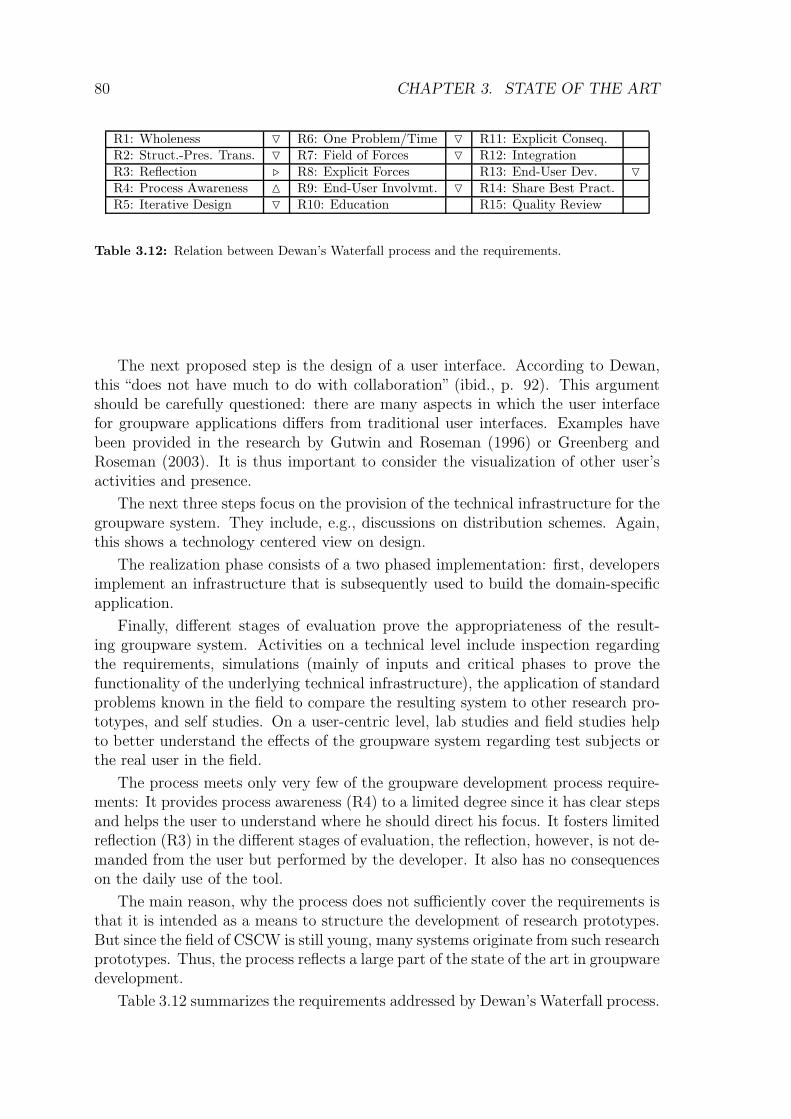
76 CHAPTER 3. STATE OF THE ART
In a complementary study, the same group of authors reports on the use of pat-tern languages in their process (Finlay et al., 2002). Results showed that patternlanguages can successfully be applied in the context of participatory design. Usersespecially relied on the examples and the bold-faced solution statements of the pat-terns. They managed to adapt patterns to their contexts (although some usersregarded the patterns as truths and discarded their own ideas of design). They alsobrought up new pattern ideas or found flaws in the pattern language.
Discussion with respect to the Groupware Development Requirements
The experiences from different application areas of pattern languages show thatpatterns can serve as supportive means in the design process. When focussing atend-user involvement, high-level patterns are especially important. These patternshave to be written in a format that is readable by both end-users and developers.Patterns from the field of HCI seem more suitable at this level of abstraction thantechnology centered patterns in the GoF style.
The connection between patterns and processes is still very limited. The mostcomprehensive approach in this direction has been proposed by Borchers. But sincehe focuses on a usability design process, he does not address the needs of veryuncertain requirements and especially not the problem of changing requirementsduring system use. The process proposed by Dearden et al. shows that parts ofthe participation laid out by Borchers can lead to success in participatory design.However, if we consider participation at the level that was envisioned by Alexander,an ideal participatory process should also address situations where the users act asimplementors of their environment.
3.1.6 Discussion of Software Development Processes
In this section, we addressed the problem of groupware development at an abstractlevel: the development of software in general and especially the development ofinteractive systems.
The process models discussed in the first part of this section showed to be moreor less flexible to changing requirements (ranging from waterfall processes to XP).End-user involvement took place at different levels, ranging from participation in therequirements specification (in the traditional waterfall process) up to a continuousinteraction between development team and the end-user (in XP).
Participation of the end-user also varies regarding the phase in which the partic-ipation took place and the technique used for structuring the interaction with theuser.
Patterns – although often used as technical tools for fostering communicationbetween designers – can be successfully applied in user-developer interaction. How-ever, if they are not combined with a flexible process model, they have only limitedimpact and support the user only in small phases of the overall development process.
Table 3.11 summarizes the contributions of the different approaches to the re-
3.1. SOFTWARE DEVELOPMENT PROCESSES 77
R1:
Whole
nes
s
R2:
Str
uct
ure
-Pre
s.Tra
nsf
orm
.
R3:
Refl
ection
R4:
Pro
cess
Aw
are
nes
s
R5:
Iter
ative
Des
ign
R6:
One
Pro
ble
mat
aT
ime
R7:
Fie
ldofForc
es
R8:
Explici
tForc
es
R9:
End-U
ser
Involv
emen
t
R10:
Educa
tion
R11:
Explici
tC
onse
quen
ces
R12:
Inte
gra
tion
R13:
End-U
ser
Dev
elopm
ent
R14:
Shari
ng
ofB
est
Pra
ctic
es
R15:
Quality
Rev
iew
Waterfall Processes O O . M . O O . O
Unified Process O O . M M O O . . O
eXtreme Programming M . M M N M O . M M O
Scrum M . N M O O . .
Feature-Driven Dev. . O . M . M O .
Participatory Design . M M M M
End-User Development M . . N N N
Software Patterns M M M M . M M O M N
HCI-Patterns M M M M M N N M M N M
Pat.-orient. usab. eng. M M M M M N M
Table 3.11: Relation between the software development approaches and the requirements.
quirements for a groupware development process. The table shows that the sumof all approaches provides a satisfying coverage of the requirements but no singleapproach can solve the problems of groupware development alone.
The table shows that a combination of an agile method like XP with HCI patternscomes very close to the full set of requirements. Weak points of XP (e.g., end-userdevelopment and structure-preserving transformations) are supported with a patternapproach. In addition, aspects regarding education and sharing of practices are notaddressed by the development processes but sufficiently covered with the use ofHCI patterns. The combination of patterns and a participatory design approachas proposed by Borchers (2000b) is a good step towards combining iterative designwith educational aspects strengthened by the use of patterns. While it reasonablyaddresses the solution of small design problems, it still needs to be extended withbetter support for coordination in order to design groupware solutions with largeruser communities.
The state of the art presented up to now considered groupware developmentas a development activity that is related to software development only. The nextsection will discuss to what extent the different development methods are found andmodified in groupware development.

78 CHAPTER 3. STATE OF THE ART
3.2 Groupware Development Processes
In this section, we will address the state of the art from a groupware developmentperspective and show how ideas from software development have been applied togroupware development.
3.2.1 A critical review of Dewan’s waterfall process modelfor groupware development
Dewan (2001) presents a traditional design process for groupware: He combines awaterfall process with additional steps for analysis. His model is shown in fig. 3.22.It is primarily intended as a development model in research contexts. AlthoughDewan explicitly states that the waterfall process can be executed several times, thefocus of the waterfall process comprises the whole product. Therefore, we can notconsider the process as iterative.
However, the different steps in the waterfall process are appropriated to theproblems in groupware design.
In the first functional decomposition step, the application’s problem space isrelated to the different areas of groupware research. Examples for functional unitsare multi-user undo, access control, or group awareness. Having such a phase asan initial step in the process is very problematic: it addresses technology-drivenquestions before examining scenarios of use and finding out what the user reallywants. This leads to technology-driven groupware-design that may lack situatedness.
However, the process model of Dewan includes steps of analysis. It suggests thatscenarios should be imagined by the developers or that a CSCW designer observesreal-world collaboration and derives scenarios for groupware support. End-users are,according to Dewan, not capable of performing this step since they lack the requiredinsights in the field of CSCW (ibid., p. 86). This attitude is problematic for theprocess. As we have shown in chapter 2, groupware support should be situated inthe user’s context. An imagined scenario of use could work, but it is more or lessa question of luck since the imagined context does not necessarily match the realuser’s context.
The requirements step is again described by Dewan from a technology centeredview. Rather than focussing on functional requirements, he discusses technologyconstraints that emerge in groupware systems such as the reuse of existing applica-tions in a shared window system or the provision of group awareness and differentmodes of coupling.
In the next step, the interaction model is defined. It describes the ways howusers interact from a high level perspective. This includes finding a metaphor (likethe metaphor of a Room) for collaboration. Dewan only vaguely describes whoperforms this step, but from the context, one can conclude that he intends that thedesigners or CSCW researchers are in charge of finding the metaphors. Again, this isproblematic since it does not ensure that the chosen metaphors are consistent withthe user’s metaphors.

3.2. GROUPWARE DEVELOPMENT PROCESSES 79
Functional Decomposition
Scenarios Principles
Requirements
Interaction model
User Interface
Logical architecture
Physical architecture
Abstractions
Infrastructure
implementation
Application development
Self studies
Inspection Simulations Standard
problems
Lab studies
Field studies
Steps common to
infrastructure and
application research
Infrastructure and
application evaluation
Figure 3.22: An adapted waterfall process for groupware development (Dewan, 2001).

80 CHAPTER 3. STATE OF THE ART
R1: Wholeness O R6: One Problem/Time O R11: Explicit Conseq.R2: Struct.-Pres. Trans. O R7: Field of Forces O R12: IntegrationR3: Reflection . R8: Explicit Forces R13: End-User Dev. O
R4: Process Awareness M R9: End-User Involvmt. O R14: Share Best Pract.R5: Iterative Design O R10: Education R15: Quality Review
Table 3.12: Relation between Dewan’s Waterfall process and the requirements.
The next proposed step is the design of a user interface. According to Dewan,this “does not have much to do with collaboration” (ibid., p. 92). This argumentshould be carefully questioned: there are many aspects in which the user interfacefor groupware applications differs from traditional user interfaces. Examples havebeen provided in the research by Gutwin and Roseman (1996) or Greenberg andRoseman (2003). It is thus important to consider the visualization of other user’sactivities and presence.
The next three steps focus on the provision of the technical infrastructure for thegroupware system. They include, e.g., discussions on distribution schemes. Again,this shows a technology centered view on design.
The realization phase consists of a two phased implementation: first, developersimplement an infrastructure that is subsequently used to build the domain-specificapplication.
Finally, different stages of evaluation prove the appropriateness of the result-ing groupware system. Activities on a technical level include inspection regardingthe requirements, simulations (mainly of inputs and critical phases to prove thefunctionality of the underlying technical infrastructure), the application of standardproblems known in the field to compare the resulting system to other research pro-totypes, and self studies. On a user-centric level, lab studies and field studies helpto better understand the effects of the groupware system regarding test subjects orthe real user in the field.
The process meets only very few of the groupware development process require-ments: It provides process awareness (R4) to a limited degree since it has clear stepsand helps the user to understand where he should direct his focus. It fosters limitedreflection (R3) in the different stages of evaluation, the reflection, however, is not de-manded from the user but performed by the developer. It also has no consequenceson the daily use of the tool.
The main reason, why the process does not sufficiently cover the requirements isthat it is intended as a means to structure the development of research prototypes.But since the field of CSCW is still young, many systems originate from such researchprototypes. Thus, the process reflects a large part of the state of the art in groupwaredevelopment.
Table 3.12 summarizes the requirements addressed by Dewan’s Waterfall process.

3.2. GROUPWARE DEVELOPMENT PROCESSES 81
3.2.2 Agile Processes for Groupware Development
Rittenbruch et al. (2002) report on the application of eXtreme Programming prac-tices for the design of a social portal (also (Mansfield et al., 2002)). The most im-portant observation made in this project was that the whole user community couldbe empowered to write user stories (compared to a user representative in XP). Forthat reason, the system had an electronic feedback mechanism that allowed users towrite stories. However, this change to the planning game required additional roles:
Ad-hoc customer: Before the early prototype could be released, there have to beusers who play the role of the customer without being real users. These ad-hoccustomers help to shape the first prototype until real users can create stories.
User-evaluation customer: In traditional XP, the customer is a representativeof future users (or business). The problem with this role is that the customerstays together with the design team and can thus gradually become a designer.Although this is good from a participation perspective, it bears the danger thatthe customer starts to think like a designer. Problems that are encountered bynew users can thus stay undetected. The user-evaluation customer has the taskof observing new users in their system use, look for interaction breakdowns,and create user stories for these users.
Design customer: In XP, only customers are allowed to create new cards. Thiscan have the effect that the customer designs the system from his personalbackground and experience. New innovative technologies that are not knownby an average customer, will often not be considered. Since many areas ofgroupware are still in their infancy, average users may design inadequate solu-tions.
Gardener: Since all users were allowed to create user stories the number of storiesgrew very fast. Therefore, users and developers had difficulties to coordinatethe proposed stories. The gardener was responsible for clustering and main-taining the user stories.
This example shows how agile methods can be appropriated for the design ofcollaborative applications. The main point is that the real user community of thesystem should be encouraged to participate in perfecting their environment.
The main difference to XP is a better involvement of the end-user (R9): Whilethe user involvement of XP focuses on interacting with one customer representative,the extended XP process proposes to involve all users. The role of the gardenerhelps to improve process awareness (R4) among all users: Since the story cards arestored in a groupware system, all users can browse and modify the cards.
Table 3.13 summarizes the requirements addressed by Extended XP process.
The only questionable role is that of the design customer. It is a work-aroundfor a lack of experience with new technology at the user’s side. However, if the userwould be educated (R10), he could be trained in these new trends and in insights

82 CHAPTER 3. STATE OF THE ART
R1: Wholeness M R6: One Problem/Time M R11: Explicit Conseq. .
R2: Struct.-Pres. Trans. . R7: Field of Forces . R12: IntegrationR3: Reflection M R8: Explicit Forces . R13: End-User Dev. O
R4: Process Awareness N R9: End-User Involvmt. N R14: Share Best Pract.R5: Iterative Design N R10: Education . R15: Quality Review
Table 3.13: Relation between Extended XP process and the requirements.
of CSCW research. Then users could create user stories that take the benefits anddrawbacks (the forces) into account (R7, R8, and R11).
3.2.3 Application of Participatory Design Methods
Participatory design methods have become quite prominent in groupware design,e.g. (Grudin, 1994). They argue that groupware systems have to be designed formodifications to suit evolution of use. An important issue of tailoring groupware isthe impact of tailoring operations: if a tailoring operation impacts other participants,they may, as a group, perform the tailoring. In that case, the users need a method todecide on a common tailoring style and a process, how tailored groupware systemsare reintegrated in the group (Fernandez et al., 2002) and thus encourage sharing ofbest practices. Most tailoring environments do not consider this.
All levels of tailoring are relevant for groupware contexts. However, tailoringactions on a high level (modifications of the content structure) can have a muchhigher impact since the content is “inhabited” or used by many users. However,as Grudin stated “using tailorable systems is a good step to providing flexibility,but to tailor effectively is a challenge, because people are not conscious of detailedorganizational functioning and how changes affect other people.” (Grudin, 1994, p.99)
The use of collaboration scenarios has been applied to different developmentprojects in the field of CSCW. Examples are the PoliTeam project (Cremers et al.,1998) that had the goal of fostering collaboration between federal ministries in Bonn(the former German capital) and Berlin (the current capital) and the SAIK project(Bardram, 2000) that applied a scenario approach to hospital information systemsin Denmark. Especially the narrative nature of scenarios served as a good meansto bridge the gap between analysis and design. In the next two subsections, twoconcrete process models that are based on participatory design will be discussed indetail: Organizational and Technical Development (OTD) and Seeding, EvolutionaryGrowth, and Reseeding (SER).
Organizational and Technological Development
With OTD (Integrated Organizational and Technological Development), Wulf et al.present an evolutionary approach to appropriate group processes and technologyto support the processes during system use (Wulf and Rohde, 1995; Wulf et al.,1999). This approach takes into account that three aspects need to co-evolve in a
3.2. GROUPWARE DEVELOPMENT PROCESSES 83
work-setting: technology that supports group processes, organizational structures,and qualification of the group members. One has to decide For each problem whichfactors need to evolve to solve the problem. The OTD model is shown in figure 3.23.
planning of
interventions
interventions
evaluation of
work system
stating a problem
system
version
organizational
development
interventions
qualificationtailoring, redesign,
removal
techno-
logy
organi-
zation
qualifi-
cation
analysis of actual state
establishing the process
qu
alific
atio
nfo
rpa
rticip
atio
n
creation of alternative options
Figure 3.23: The OTD model (Wulf and Rohde, 1995).
After the problem is established, a group of stakeholders investigates the currentstate of the organization. The group should include all people who are affected by theproblem. If the investigation comes to the conclusion that the problem is relevant,they create alternative options. They utilize different techniques from participatorydesign (stories, software prototypes, etc.) to foster mutual understanding.
According to the type of problem, the group determines technology, organiza-tional, and qualification factors that should be changed. In case of a technologyissue, the users appropriate the system by means of tailoring or developers per-form a redesign (including the possibility for removing the system). In case of anorganizational factor, the group processes are changed (which does not mean thattechnology also has to change). Finally, if the problem is a result of qualification

84 CHAPTER 3. STATE OF THE ART
R1: Wholeness R6: One Problem/Time . R11: Explicit Conseq.R2: Struct.-Pres. Trans. R7: Field of Forces M R12: IntegrationR3: Reflection M R8: Explicit Forces M R13: End-User Dev. N
R4: Process Awareness M R9: End-User Involvmt. N R14: Share Best Pract.R5: Iterative Design M R10: Education M R15: Quality Review
Table 3.14: Relation between OTD and the requirements.
deficits, a qualification program for the stakeholders is developed. Note that allthree aspects can co-occur.
The result is a modified system that can be used until the next breakdown.
The OTD process comes very close to satisfying all requirements. It fostersreflection (steps evaluation of current work and stating a problem – R3), processawareness (R4), and iterative design (R5). By letting the stakeholders analyze thecurrent state, the forces of the current situation become explicit (R7, R8). Theend-user is involved throughout the process R9 and performs modifications throughtailoring (R13). Finally, qualification for participation is considered as an integralpart of the process, which satisfies R10.
Open issues are the sharing of best practices, the ways how changed artifactsare embedded in the environment R12 and the question whether or not the processcreates coherent system designs (R1 and R2). The size of the iterations is not definedby OTD (R6).
Table 3.14 summarizes the requirements addressed by OTD.
SER - Seeding, Evolutionary Growth, and Reseeding
Fischer et al. (2001) propose a process model for collaboratively designing user’s en-vironments (especially collaboratively used information systems – IS). They proposethree different stages for supporting design groups:
Seeding. At the beginning of a cycle, environment developers and future userscapture their domain knowledge and requirements for the IS infrastructure.The resulting system serves as a seed for the next phase. It is a rather smallcollection of domain knowledge that is designed to evolve over time.
Evolutionary growth takes place when users use the IS as a tool to perform theirwork. Two main purposes are served by the seed:
1. it serves as a tool for solving domain related problems, and
2. it serves as a knowledge store since the solutions of former domain relatedproblems are captured in the IS.
Reseeding. Whenever the use of former knowledge (obtained from results of theevolutionary growth phase) becomes complicated, environment developers anddomain designers can start a phase of reseeding. The goal of this phase is to

3.2. GROUPWARE DEVELOPMENT PROCESSES 85
R1: Wholeness R6: One Problem/Time R11: Explicit Conseq.R2: Struct.-Pres. Trans. R7: Field of Forces R12: IntegrationR3: Reflection M R8: Explicit Forces R13: End-User Dev.R4: Process Awareness R9: End-User Involvmt. M R14: Share Best Pract. M
R5: Iterative Design M R10: Education M R15: Quality Review M
Table 3.15: Relation between SER and the requirements.
reorganize, formalize, and generalize the information collected during evolu-tionary growth.
The main difference to other participatory design approaches lies in the empha-sis of mutual learning. Users let the knowledge of all stakeholders in the designprocess evolve during use. This is why the authors of the SER model call the in-volvement of users informed participation. Participatory design instead focuses onthe construction of artifacts.
According to Fischer et al. (ibid.), informed participation is supported by refer-ring to comparable problems of the past. How these problems and solutions shouldbe represented to support quick access to captured knowledge is not discussed inSER.
Table 3.15 summarizes the requirements addressed by SER. The strengths ofSER are in the process of reflection (while appropriating the system – R3) and inthe sharing of reflection results (R14). The reseeding phase ensures that the sharedknowledge wll be structured and assessed (R15).
3.2.4 CSCW Patterns
First patterns for the design of groupware applications focussed only on technicalaspects like replication, session management or concurrency control (Guerrero andFuller, 1999), (Schummer et al., 1999), (David et al., 2003). They were written in adeveloper-centered format (comparable to the GoF patterns). Thus, these patternscan support developers in finding out how to apply a specific solution but are notsuited to support communication between end-users and developers.
In ethnography-centered CSCW research, patterns have been used to categorizeobservations in field work (Martin et al., 2001; Crabtree et al., 2002). In this context,patterns have a descriptive goal. They thus do not state problems and solutions butrather report on recurring behavior in the observed social system.
An example pattern from an ethnographic pattern language is provided in fig.3.24. The pattern states what the recurring behavior is (Essence of the Patternsection). The following part speculates on reasons why a specific behavior recursand why it could be considered as helpful. Illustrations in forms of Vignettes providedescriptions on ethnographic studies where the behavior was found. Again, theillustrations only describe and do not prescribe behavior. In the last section labeleddependability implications, the pattern informs the reader about possible problems

86 CHAPTER 3. STATE OF THE ART
Figure 3.24: An example pattern from the pointer pattern language. Reprint from
http://polo.lancs.ac.uk/patterns/WorkWithInterruptions.
in the observed context. This relates to a liabilities section of traditional patternformats.
Martin et al. (2002) discussed the application of ethnographic patterns. Theyprimarily serve as triggers for discussion in the phase of requirements elicitation andearly design. They help users to reflect on their specific situations. However, thesepatterns do not suggest a specific design.
Several authors from the design patterns community have focussed on describingsocial processes with patterns. Frequently recurring themes are pattern languagesdescribing software development processes (e.g., a pattern language focussing on thedelivery phase of a software development process (Prince and Schneider, 2004)) orpattern languages discussing group management issues (e.g. the project on Orga-nizational Patterns (Coplien and Harrison, 2004 (to be published)) or the pattern

3.2. GROUPWARE DEVELOPMENT PROCESSES 87
language by Manns and Rising (2004) that discusses the process of changing orga-nizational structures and traditions). These patterns can be considered as socialpatterns. They are very valuable for understanding social processes in organiza-tions. However, they do not assist the user in applying the proposed solution in acomputer-mediated context.
Since the CSCW2002 workshop on Socio-Technical Pattern Languages, a seriesof workshops focussed on the appropriation of the pattern approach to the high-leveldesign of groupware systems. The workshops helped to bring together the organi-zational and the technical view of patterns for group support. The fact that theworkshops took place at different conferences also helped to gain different perspec-tives on the groupware patterns theme.
The workshops had the following foci:
– The CSCW2002 workshop on socio-technical pattern languages (Thomas et al.,2002) focussed on factors that create a pattern language from individual pat-terns and on attributes of socio-technical patterns. It brought together re-searchers from ethnographic, sociologic, economic, and technical backgrounds.
It became clear that the interpretation of the nature of a pattern differedgreatly. The ethnographic interpretation (see above sections) focuses on de-scribing interaction without prescribing a design. Sociologic interpretationsfocussed on the human interaction and the question of how to shape processes.There was only a limited use of technology aspects. Technology-centered viewsapproached the field of socio-technical patterns from the perspective of tech-nical possibilities. In the discussions it became clear that both technology andsocial aspects need to be addressed in socio-technical patterns.
Another discussion regarded the form of patterns: Again, the participantspresented different approaches ranging from literal Alexandrian presentationsup to technology oriented presentations (including technical diagrams with anotation that the reader has to learn before being able to understand the pat-tern). One consensus was that the patterns should be readable by end-users.The role of narrative descriptions was appreciated by most of the participants.
– A sequel of the CSCW2002 workshop was the ECSCW2003 workshop “Fromgood practices to patterns” (Herrmann et al., 2003b). The goal was to bet-ter understand the process of finding patterns in the research area of CSCW.Participants submitted initial versions of patterns and descriptions focus areasthat could be interesting for pattern mining. During the workshop, these focusareas were further examined and pattern candidates as well as first prototypicalpatterns were detected. Again, the participants came from different disciplinesincluding education, ethnography, software development, and socio-technicalresearch. Although mostly convinced of the possibilities for the applicationof patterns in the context of CSCW, the participants stayed sceptic aboutthe current practical implications. Two issues were considered as problematic:(1) the community did not recognize patterns as tools for groupware develop-ment yet and (2) there is still a lack of a comprehensive pattern language for

88 CHAPTER 3. STATE OF THE ART
groupware development.
– At CHI2004, the organizers of the workshop on “Human-Computer-HumanInteraction Patterns” (Schummer et al., 2004)16 approached the field of group-ware patterns in the CHI context. The workshop built on experiences fromformer pattern-related workshops of CHI and tried to bring together expertsin HCI patterns and groupware experts.
The discussions focussed on four different hot topics for the development ofcollaborative systems: (1) design issues for large scale communities with a fo-cus on e-democracy, (2) the design of physical collaboration environments,(3) problems and perspectives for computer-mediated communication, and(4) technology issues regarding groupware service composition. The topicswere chosen to gain a holistic view on the full spectrum of computer-mediatedhuman-human interaction ranging from large scale political issues over mediumscaled issues for small group interaction up to issues regarding the supportivetechnology.
Figure 3.25: Patterns for supporting computer-mediated communication. Results of the CHI2004
workshop sub-group that I moderated.
Participants split into four groups and created a pattern landscape for eacharea. The structure of one result is shown in fig. 3.25 showing patterns in thecontext of computer-mediated communication.
16see also http://www.hcipatterns.org/CHI2004Workshop.html.

3.2. GROUPWARE DEVELOPMENT PROCESSES 89
Besides drawing a landscape of relevant areas for pattern languages, the focuswas on how to ensure the quality of a pattern language for human-computer-human interaction. Participants practiced Writer’s Workshops, a review tech-nique that is widely applied at PLoP conferences17 but not common in theHCI patterns community.
– A focus group at EuroPLoP 2004 also stressed the process of mining Human-Computer-Human-Interaction patterns as well (Schummer and Zdun, 2004).Due to the expertise of the participants, it primarily focussed on patterns forsupporting collaborative learning. While the other workshops primarily fo-cussed on pattern representations and techniques for improving pattern qual-ity, the EuroPLoP workshop put special attention on the described subject,namely, the collaborative learning process. The result was a small set of pat-terns regarding role assignment in CSCL.
– Finally, a workshop at INTERACT2005 (”Workshop on HCI patterns: Map-ping User Needs into Interaction Design Solutions”)18 will merge the results ofthe above workshops under the perspective of process integration of patterns.
Besides the workshop activities, two major publications appeared recently ad-dressing the topic of groupware patterns. At CRIWG 2004, Lukosch and Schummer(2004a) discussed the applicability of patterns for groupware from a technical, butstill narrative, perspective. The paper reported on low-level parts of the patternlanguage used in this thesis. Thus, we will not discuss the contribution of this workto the state of the art now, but rather have a look on how these patterns integratewith the rest of this thesis in chapter 4. The second recent publication argued forthe use of socio-technical pattern languages in CSCW (Herrmann et al., 2003a).The authors captured discussions from the CSCW2002 workshop and proposed tocombine the pattern approach with their socio-technical modelling technique SeeMe(Herrmann et al., 2000) and applied this combined pattern format to the researcharea of knowledge management. The problem that we see with this approach is theuse of diagrams. Although diagrams can be successfully used as illustrative vehicles,they require learning effort regarding the notation. A pure Alexandrian format ofpatterns that focuses on narration could thus be more suitable.
The workshops provide a comprehensive picture of current activities in the col-lection of patterns for collaborative systems. Several researchers have made firstexperiences with collecting socio-technical patterns, but the sizes of the collectedpattern sets only provides anecdotal evidence for the existence of patterns in CSCW.Unlike in the HCI patterns community, the groupware patterns community has notyet reached the state where a widely accepted pattern format is reached. Regarding
17PLoP = Pattern Languages of Programs. The PLoP conferences have the goal of collectingpatterns of various domains and bring together researchers from different fields related to the useor development of software. Unlike at other conferences, the focus is not mainly on innovationof new technologies but on the art of presenting patterns so that they have the highest possibleoutcome for an intended readership (e.g. for end-users).
18organized by Franca Garzotto, Symeon Retalis, Till Schummer, Uwe Zdun, and StephanLukosch

90 CHAPTER 3. STATE OF THE ART
R1: Wholeness R6: One Problem/Time M R11: Explicit Conseq. M
R2: Struct.-Pres. Trans. M R7: Field of Forces M R12: IntegrationR3: Reflection R8: Explicit Forces M R13: End-User Dev. O
R4: Process Awareness R9: End-User Involvmt. O R14: Share Best Pract. M
R5: Iterative Design R10: Education M R15: Quality Review M
Table 3.16: Relation between CSCW Technology Patterns and the requirements.
R1: Wholeness R6: One Problem/Time R11: Explicit Conseq. O
R2: Struct.-Pres. Trans. R7: Field of Forces M R12: IntegrationR3: Reflection M R8: Explicit Forces M R13: End-User Dev.R4: Process Awareness R9: End-User Involvmt. R14: Share Best Pract. O
R5: Iterative Design R10: Education O R15: Quality Review
Table 3.17: Relation between Ethnographic Patterns and the requirements.
the different scientific backgrounds (socio-technical research, ethnography, or soft-ware engineering to name only a few), one can be doubtful that such a consensuswill be reached soon.
When considering patterns as tools, they help to support the requirements ofchapter 2 do different extents. Technology patterns (summarized in table 3.16)focus on supporting the developer. They help to develop the system in structure-preserving transformations (R2) from a technical point of view. When applying atechnology pattern, the developer concentrates at one specific problem (R6) in itscontext (R7, R8) keeping in mind the consequences described in the pattern (R11).The pattern serves a as an educative means between developers (R10). Technologypatterns are however not focusing on the end-user (R9, R13). The PLoP communityhas established review and shepherding processes that help to raise the quality oftechnology patterns (R15). All major collections of CSCW technology patterns wentthrough such a process or are currently shepherded. Thus, we can assume that theyare of high quality.
Ethnographic patterns (summarized in table 3.17) are intended to be used in thediscussion between designers and users. They serve as a tool for reflection (R3) byproviding access to ethnographic studies in comparable contexts. They describe theinteraction in the observed scenario (R7) and try to argue why a specific behaviortook place (R8). However, they do not intend to communicate a solution. They arenot helping the user how to solve a specific problem (violating R10) and can thereforebe considered as means for sharing descriptions of practices but not necessarily ofbest practices (violating R14). Since they do not provide solutions, they as well donot help to understand consequences of a specific solution (violating R11).
The degree to which socio-technical patterns can help to meet the process re-quirements depends on the way they are used by the users and developers. TheCSCW community still lacks an approach for supporting the application of patternsin a groupware design process. However, if we assume that the patterns are usedin a participatory iterative process, they can capture design knowledge in a way

3.3. SUMMARY OF THE FIRST PART 91
R1: Wholeness R6: One Problem/Time M R11: Explicit Conseq. M
R2: Struct.-Pres. Trans. M R7: Field of Forces M R12: Integration M
R3: Reflection M R8: Explicit Forces M R13: End-User Dev. M
R4: Process Awareness R9: End-User Involvmt. N R14: Share Best Pract. N
R5: Iterative Design R10: Education N R15: Quality Review M
Table 3.18: Relation between Socio-Technical Patterns and the requirements.
that is easily accessible by end-users and developers. They help the developer andthe user to create structure-preserving transformations (R2). When used by theend-users in a break situation, they also support reflection (R3) since they report oncomparable recurring problems of other users and provide solutions to these prob-lems. The reader of the pattern will concentrate on the pattern’s problem (R6)and investigate its context (R7) and forces (R8). Since the patterns are writtenfor end-users, they help to educate the user (R10) so that he can make informeddesign decisions (R9) that take potential drawbacks into account (R11). The pat-terns address both the technical and the social parts of the problem. In many cases,the solution can be implemented by a changed social process. In such cases, theusers will change their work style and in this sense implement the pattern on theirown (R13). Finally, users of a collaborative application should be encouraged toshare their socio-technical patterns (R14 and R15). To what extent this is practiceddepends on the climate of knowledge sharing in the users’ context.
3.3 Summary of the first part
Table 3.19 provides a summary of the first part of the thesis. We have seen thatdifferent approaches to design suggest 15 requirements for a groupware developmentprocess (cf. chapter 2). The different approaches to design provide the theoreticand methodic background for such an ideal groupware development process.
As shown in the upper part of table 3.19, the different approaches influenced oneanother but no theoretic model meets all requirements. The Oregon Experimentis very close to an ideal model but it still lacks properties addressing wholenessand structure-preserving transformations. The theory from Alexander (2003a) canextend the Oregon Experiment to fill this gap.
The considered state of the art for software development support shows twonearly complementary clusters:
1. Design methodologies (the waterfall process, the Unified Process, eXtremeProgramming, Scrum, and Feature-Driven Development) support those re-quirements that focus on analyzing the problem and structuring the solutionprocess in a way that the problem is simple enough to be addressed in theproject. Agile methods have strengths in their way to break down the prob-lem in tasks and prioritize the tasks in order to build a system that meets theusers’ most important requirements. Especially eXtreme Programming puts

92 CHAPTER 3. STATE OF THE ART
R1:
Whole
nes
s
R2:
Str
uct
ure
-Pre
s.Tra
nsf
orm
.
R3:
Refl
ection
R4:
Pro
cess
Aw
are
nes
s
R5:
Iter
ative
Des
ign
R6:
One
Pro
ble
mat
aT
ime
R7:
Fie
ldofForc
es
R8:
Explici
tForc
es
R9:
End-U
ser
Involv
emen
t
R10:
Educa
tion
R11:
Explici
tC
onse
quen
ces
R12:
Inte
gra
tion
R13:
End-U
ser
Dev
elopm
ent
R14:
Shari
ng
ofB
est
Pra
ctic
es
R15:
Quality
Rev
iew
Situatedness M M M M M M M M M
Synthesis of Form M M M M
A City is not a Tree M M M M
Wicked Problem M M
Reflection-in-Action M M M M M M M M
PDSA M M M M M M
Patterns M M M M M M M M
Gen. Centers & Memes M M M M
Oregon Experiment M M M M M M M M M M M M
Participatory Design M M M M
Holism & Wholeness M M M
Structure-Pres. Transf. M M M M M M M M
Rugby Approach M M M M M M M
Waterfall Processes O O . M . O O . O
Unified Process O O . M M O O . . O
eXtreme Programming M . M M N M O . M M O
Scrum M . N M O O . .
Feature-Driven Dev. . O . M . M O .
Participatory Design . M M M M
End-User Development M . . N N N
Software Patterns M M M M . M M O M N
HCI-Patterns M M M M M N N M M N M
Pat.-orient. usab. eng. M M M M M N M
Dewan’s Waterfall O O . M O O O O O
extended XP M . M N N M . . N . . O
OTD M M M . M M N M N
SER M M M M M M
CSCW Techn. Patterns M M M M O M M O M M
Ethnographic Patterns M M M O O O
Socio-Techn. Patterns M M M M M N N M M M N M
Table 3.19: Relation between development approaches and the requirements.
3.3. SUMMARY OF THE FIRST PART 93
a focus on the end-user and considers him as the most authoritative instancefor structuring the development activities. It is the customer who decides onthe next steps for each very short iteration.
2. Educative tools that focus on empowering the end-user to make informed de-sign decisions (the pattern approaches). Users should learn best practices andshare these practices with other users. It is important that the users find away to communicate the best practices. The pattern approaches address thisissue. Especially HCI patterns focus on teaching the end-user in designinghis system. Participatory design and end-user development provide a processcontext in which patterns can be applied by end-users.
An ideal groupware process should combine techniques and tools from both clus-ters. However, we can see the same set of clusters in the state of the art consideredfor groupware development support. In cases where traditional software develop-ment processes were appropriated for groupware development, little focus has beenon the education of the end-user and the sharing of best practices. Groupware spe-cific processes (OTD and SER) approach the user involvement by either offeringopportunities for tailoring or by capturing best practices. But still, they have nosystematic approach for capturing and sharing the knowledge.
As in the broader context of software development, a pattern approach thatfocuses on socio-technical patterns can fill this gap. If combined with an agile processmodel (i.e., the extended XP model) and enriched by an environment that supportstailoring and sharing of best practices, it can probably meet all requirements.
This is the approach that we will follow in the second part of this thesis. Wewill present the Oregon Software Development Process model that combines theextended XP model with the use of socio-technical patterns.

94 CHAPTER 3. STATE OF THE ART

Chapter 4
A Pattern Approach forGroupware Development
In the remaining part of this thesis we will propose a new development process thatcombines patterns with aspects of agile processes in order to satisfy the requirementsof chapter 2. The remaining part is structured as follows: In this chapter, we willdiscuss the process model (section 4.1) and the pattern structure for socio-technicalgroupware patterns that support educational aspects of the process (section 4.2).Chapter 5 will present a small set of patterns for supporting group formation basedon increased group awareness. The application of these and related patterns is thesubject of chapter 6. We will present observations from a field study where theprocess and the patterns were applied to build a collaborative learning platform(section 6.2 ff.). This study will be complemented with theoretic considerationsregarding pattern sequences (section 6.4.3) and experiences from smaller studentprojects (section 6.6).
4.1 The Oregon Software Development Process
The Oregon Software Development Process (OSDP) intends to foster end-user par-ticipation, pattern-oriented transfer of design knowledge, piecemeal growth of thesystem under development in the form of short iterations, and frequent diagnosis orreflection that lead to an improved application.
Figure 4.1 shows the different phases of the OSDP. It suggests three differentkinds of iterations – conceptual iterations (section 4.1.1), development iterations(section 4.1.2), and tailoring iterations (section 4.1.3) – denoted by the three circles.After introducing the iterations, we will relate the whole process to the requirements(section 4.1.5) and compare it with other processes (section 4.1.6).
4.1.1 Conceptual Iteration
The role of the conceptual iterations is twofold: they should help the users to forma project group and norm their goals in the participatory process.
95

96 CHAPTER 4. APPROACH
Ex
pe
rtIn
vo
lve
me
nt
3
8
2
6
11
5
7
9
Us
er
Inv
olv
em
en
t
4 1
Analysis
of forces
Planning
Conflicting
forces
Des
ignP
atte
rn d
riven
tailo
ring
design
- high
leve
l pat
tern
s -P
atte
rn d
riven
grou
pwar
e de
sign
- low
leve
l pat
tern
s -S
cena
rios
Implem
entation
Patterns
& m
ockups
Pattern driven
groupware tailoring
Test &
Usa
ge
Usa
ge w
ith
diag
nosis & re
flection
- hea
lth m
ap -
func
tiona
l tes
ts
Conceptualiteration
developmentiteration
tailoringiteration
Initialforces
Groupw
are
development
Discu
ssion
10
12
Figure 4.1: The Oregon Software Development Process.
The first conceptual iterations will have a special focus on group formation, asit was proposed by Tuckman and Jenson (1977). They proposed that a group’s lifecycle runs through five different stages beginning with the first meeting of the groupup to the end of group work. The first three stages describe how the group lays thefoundation for future collaboration. These three stages are:
Forming is the stage where group members become aware of the other user’s iden-tities. They will also get an idea of the group goals and activities.
Storming , as the name suggests, is the stage where initial conflicts are fought out.Examples for such conflicts can be an unequal participation in the group orthe fight for group leader roles.
Norming represents the stage of the group process where the group members havefound their position in the group. Group members start to constructivelydesign their group interaction and define group goals.
Conceptual iterations are initiated from within the organization. Users or man-agement bring in ideas for change in the organization. These ideas serve as seed forthe interaction between end-users and developers in conceptual iterations. The ideasshould evolve from concrete needs, but still leave an open area for participation ofthe users. Examples are the support of computer-mediated distance education in atraditional university, the creation of a support community for users of an indus-trial product, or the support of a community of circumstances for teenagers hittingpuberty.

4.1. THE OREGON SOFTWARE DEVELOPMENT PROCESS 97
The extent to which real users can be involved in early conceptual iterationsdepends on the existence of the user community. If the goal of the project is toestablish a user community that did not exist before, it can be very problematic tofind initial users that can be involved in the group process (cf. the discussion of XPin the context of groupware development – section 3.2.2). In this case, it can bereasonably to look for people who are close enough to the future users. Taking theexample of the university aiming at computer-mediated distance education, it makessense to find users from the following groups: students studying at a traditionaluniversity, students from distance teaching universities, teaching staff, employedpeople who for time reasons cannot participate at a traditional university but feelthe need for additional training.
These users are invited to participate in a focus group that runs the conceptualiterations. Such an iteration consists out of four main activities (numbers in thetext refer to the numbers in fig. 4.1): (1) the collection of forces, (2) the envisioningof scenarios, (3) the selection of patterns and the creation of low-fidelity prototypes,and (4) the reflection on the created scenarios and prototypes.
In the first step, users exchange stories from their workplace that are related tothe seed ideas. In the example of an industrial support community, a technicianwould for instance describe how he managed a phone call from a user. The user, onthe other hand, would describe a situation in which he needs support and how henormally acts to receive help. The stories are an important source for finding initial(high-level) forces (1).1
A special attention is put on break situations. Two questions are asked: Whatis difficult in the current practice of interaction? What are the reasons for thesedifficulties? The first question focuses on reflection and the detection of a breakwhile the second question focuses on better understanding the break and detectingthe forces that led to the break.
For each story, a scenario interest group (SIG) is formed including those users,who brought up the story, and the development team. The SIGs contrast the storieswith a scenario for future use (2). This scenario envisions the future structure ofinteraction at a very high level of abstraction. SIG members then relate the scenariosto forces and discuss which forces are addressed in the future scenario. The extentto which the forces can be made explicit depends on the certainty that users haveregarding the domain task. In most cases, this will still be very vague.
In an implementation phase of the conceptual iteration (3), the users look forpatterns that can support the envisioned scenarios. The patterns, in return, reshapethe scenarios since they can bring up related or new aspects of technology use thatwere unfamiliar to the participants who created the initial scenario. The specialfocus is on the scenario part of the patterns since it tells a related story to the user.The pattern scenarios are on the same level of abstraction as the stories created bythe users (in the first phase). An example for a pattern scenario is shown below:
Consider Maria, an inhabitant of Munich. She knows many people living in her
1Note that we prefer the term forces instead of requirements. In the Alexandrian sense, forcesexist in space. They may be at different levels of attention and emerge to requirements.

98 CHAPTER 4. APPROACH
vicinity. One day, she decides to invite all of them to her birthday party. But since
she knows the other people only by name, she has to look up all their addresses. She
takes a look at the telephone book and looks up her first contact called Alfred Meier
and is shocked by the 1280 people called Meier in Munich. It takes her some time to
find Alfred but even then she finds 11 people called Alfred Meier in Munich. Thus,
the number of unimportant Meiers is much too large and Maria spends a long time
to look up all neighbors that she wanted to invite to her party.2
The scenarios of the patterns inform the design of the future scenario. Throughanalogy with their stories, the users may detect that additional forces are addressedby the pattern. Thus, adding the pattern solution to the scenario can help to addressthese up to then ignored forces. The patterns also propose a concrete solution. Usersconsider the solution and think about how the solution matches with the inventedscenario. The scenarios are finally attributed with the patterns that are relevant fora specific the individual steps of the scenario. In addition, these patterns are addedto the group’s pattern language (together with additional patterns that are closelyrelated).
The patterns and the scenarios are used to create low-fidelity prototypes of thesystem. Users are supported by the examples provided in the patterns that illus-trate how the individual patterns have been reflected in the user interface of someapplications.
The prototypes and the pattern-attributed scenarios are then discussed (4) inthe whole group. The group performs a ranking of the scenarios and selects aspecific number of scenarios that should be implemented in subsequent developmentiterations.
Besides the detection of first functional forces, the conceptual iteration will setthe stage for future development. This includes that a system metaphor (as de-manded by XP) is found and used in the scenarios. It also requires that the usersget a first impression of efforts and possibilities of the new or changed system. Theprototypes provide a very vivid idea of how the system could be changed. The meth-ods used in the conceptual iterations are related to methods employed in traditionalparticipatory design and complemented by the use of high-level patterns.
4.1.2 Development Iteration
In the development iterations, the scenarios are further refined by the SIGs. All SIGmembers meet for a planning game (5). They discuss the most obvious forces thatappear in the scenario. These forces are written on story cards together with thespecific part of the scenario that is in conflict with or supporting to the force. Theresult is a set of user story cards (as in XP).
Users again refer to high-level patterns to inform their process of decompositionand solution design. They provide answers to the questions stated in the pattern.
2From the Buddy List→227 pattern, initially published in (Schummer, 2004c) – A note regard-
ing the pattern notation: References to patterns show the pattern name and the page number onwhich the pattern is explained set in a subscript font.

4.1. THE OREGON SOFTWARE DEVELOPMENT PROCESS 99
As long as the pattern language is, like the original Alexandrian example, organizedusing different levels of scale, the decomposition can follow the connection betweenthe different levels of scale. At the same time, developers refer to low level patternsto answer more technical questions raised by the user story (6). Users and devel-opers can propose additional patterns at this stage of the process. These will beconsidered as preliminary patterns that have not yet shown their validity. However,they should be documented by means of patterns since the pattern language servesas the community’s design memory and vocabulary.
The patterns are connected to the stories in order to inform later implementationof the story. Developers further attribute the stories with a rough effort estimate(in pair programming hours).
As in XP and Feature Driven Development, users can then “go shopping” and“buy” user stories. At each shopping step, they are only allowed to buy a fixed, butsmall, number of hours (in the field study we used 16-24 hours = 2-3 days). Thisresults in an ordering of the user stories comparable to Scrum’s backlog.
At any time in the process, users are encouraged to provide feedback regardingstories that are on the backlog and reorder or modify the stories. Unlike in Scrum,the users can modify stories until a developer begins implementing them. This hasthe effect that the user has continuous control over the direction of developmentactions taken by the developers.
On the other hand, this has the drawback that fixed milestones (containingfunctional and temporal fixtures) are no longer possible. The users thus have to agreewith the development team that functionality will always be developed regardingthe backlog, and that the development team is paid regarding the real efforts. Trustbetween developers and users is an important factor when working together on thisbasis. The developers have to trust the customers that they will be able to statetheir most urgent wishes. Customers in return have to trust that the developers willcreate a system that satisfies exactly those most urgent wishes and that they putefforts in solving these wishes that is worth paying for.
Since different SIGs can work on different scenarios in parallel, the creation ofdifferent backlogs has to be coordinated. We propose four different types of backlogs:project backlogs, SIG backlogs, end-user backlogs, and non-functional requirementsbacklogs. They will be discussed below.
The most important backlogs are the SIG backlogs. They hold the task cardsfrom the SIGs that were formally appointed by the user community. One prob-lem with XP is that it may be difficult to convince the customer of the need of arefactoring. This is the reason why the OSDP adds an artificial SIG, the systemmaintenance SIG, that is responsible for detecting design smells in the system. Thesystem maintenance SIG has the same rights as the other SIGs. Members collectand prioritize tasks in the system maintenance SIG backlog.
Stories that are brought up by users without the context of a special SIG arecollected in an end-user SIG backlog. They are rather difficult to prioritize sincethey emerged from different users with potentially different goals. Thus, the end-userbacklog will be addressed on a first-come first served basis.

100 CHAPTER 4. APPROACH
4
3
2
1
4
3
2
1
3
2
1
4
3
2
1
SIG SIGSystem
Maintenance SIG End-User SIG
4
21 3
Project Backlog
SIG Backlogs
1 2 2 1 ...
Figure 4.2: Different backlogs in the OSDP.
As proposed by Rittenbruch et al. (2002), the team member with the role ofthe gardener is responsible for coordinating the different backlogs. She observes thedifferent backlogs created by the teams and creates a scheduling that is comparablyfair for all SIGs (a round-robin strategy can already be sufficient). The SIGs areinformed of the merged schedule for story cards and can comment on this schedule,e.g., to convince the gardener that two cards of this merged schedule should beswapped.
Figure 4.2 shows an example of a project with two scenario-specific SIGs, theartificial system maintenance SIG, and the end-user SIG. All SIGs have their back-logs. The gardener takes cards from these backlogs nd adds the cards to the projectbacklog.
Instead of adding all stories to a set, the gardener can look for comparable stories(or overlaps in stories). Whenever she detects redundancy, she proposes a rewritingof the stories. The SIGs or the gardener then proposes a new set of merged stories.In fig. 4.2, the first task of the star SIG overlapped with the first card of the systemmaintenance SIG. The gardener therefore took both cards and created one mergedcard. The third task of the star SIG was identical with the fourth task of thecross SIG. Even though the cross SIG’s previous cards were not yet scheduled, thegardener can decide to combine a less important cross task card with a star taskcard rated as important by the star SIG.
As long as no stakeholder disagrees, the development team will implement themost urgent task from the backlog.
In the implementation step (7), developers provide a software solution for thefirst card from the backlog and an automated test (8) to confirm the solution’sconformance to the users’ wishes. Developers typically implement a pattern bymeans of application frameworks or developer-centered component frameworks. Thismay involve the development of new software components. Such components can be

4.1. THE OREGON SOFTWARE DEVELOPMENT PROCESS 101
built using frameworks or other base technologies. The developer uses the answerto the questions provided in the check section and the information provided in thecollaborations section to inform his design. Note that the order of testing andimplementation can be reversed (like in XP).
After the first user story is implemented the users get access to the system andstart using it (as far as the system supports the user in performing his tasks). Thesystem use will result in modifications of the backlog as well as in tailoring iterations.The latter are described in the next subsection.
4.1.3 Tailoring Iteration
In the tailoring iteration end-users use the application for the desired purpose. Whileusing the system end-users with pattern-based design knowledge are encouraged toreflect on their activities whenever they encounter a breakdown (9). A breakdownleads to an entry in the groupware’s health map (in the simple case, a note thata specific group need could not be satisfied with the groupware system). In caseswhere the user does not detect this breakdown (i.e., if the user feels uncomfortablebut thinks that this feeling cannot be changed), an evaluation user (cf. section 3.2.2)can expose the breakdown, discuss it with the user, and initiate a reflection processtogether with the user.
Users then take a closer look at the detected shortcoming. First, they analyze theforces that are in conflict (10). High-level groupware patterns help in this processby describing frequently occurring issues, the various forces, and a proven solutionin a way that is appropriate for tailoring end-users.
The solution provided by the high level patterns informs the successive groupwaretailoring design (11) and the execution of the tailoring (12). Tailoring actions cantake place at different levels. In content level tailoring, the users change the artifactsthat are managed by the groupware system in order to solve the problem. Atthis level, the pattern assists the user in using a tool. At the functional level,users appropriate the functionality provided by the tool. They activate neededfunctions and deactivate functions that are in the way. At the component level, theusers perform more extensive tailoring actions: they compose functional groupwarecomponents in order to create new configurations of applications that support theteam in an unanticipated way.
To support tailoring as a group level, a pattern scout looks for solutions thatwork well. As the evaluation user, the pattern scout observes users in the systemwith the goal of finding recurring successful system use. The found best practice isthen discussed with the users and documented in the pattern format. Such new bestpractices then find their way in the pattern catalogue. Note that these patterns are inmost cases very domain specific (e.g. patterns for supporting customer relationshipmanagement in the context of a support system). On the other hand, these patternswill be used most frequently in the user community since they are appropriated forthe interaction that typically takes place in the community.

102 CHAPTER 4. APPROACH
4.1.4 The relation between the different iteration types
During project life, the different kinds of iterations will be executed in differentfrequencies as shown in figure 4.3. Fig. 4.3 does not forecast exact frequencies overtime. Rather, typical relationships between the frequencies of the different iterationtypes are shown.
importance
developmentiterations
conceptualiterations
tailoringiterations
project timeline
iterationtype
Figure 4.3: Frequency of iterations during the project.
At project start conceptual iterations are the most important iterations. Proto-typical development accompanies the gathering of use cases and patterns in develop-ment iterations. While the project evolves the frequency of development iterationsgrows and conceptual iterations are not as important anymore. Since the devel-opment iterations produce more sophisticated prototypes users will start using thesystem more frequently and reflect on their system use. Thus, the number of user-triggered tailoring iterations increases towards the end of the project while the othertwo kinds of iterations become less important.
Users can decide to switch from a tailoring iteration to a development iterationif the needed action seems to require a more specialized treatment. In this case theycreate a story card and add it to the end-user backlog. The gardener will examinethe story card and propose an insertion point in the project backlog.
Tailoring and development iterations are expected to focus on the intended sce-narios of system use. If new scenarios evolve that are not variations of the initialscenarios, the group should perform conceptual iterations.
As suggested by figure 4.3, the different iterations can take place at the sametime in the project. A part of the development team may perform iterations ofone kind while another part of the team concurrently performs iterations of anothertype. The different sub-teams coordinate by means of the project backlog that ismaintained by a gardener. It is the gardener’s task to maintain consistency betweenthe different sub-teams.
4.1.5 Requirements addressed by OSDP
The OSDP aims to satisfy all requirements for groupware development as discussedin chapter 2. The relation between requirements and practices is discussed in the

4.1. THE OREGON SOFTWARE DEVELOPMENT PROCESS 103
following list on a theoretical level (the practical comparison will follow in chapter6):
R1: Wholeness. The project backlog addresses the development of the systemfrom a holistic perspective. This, however, does not ensure that the resultingproduct will have a high level of wholeness. Automated tests of built systemcomponents contribute to the requirement of wholeness. Since they checkwhether old requirements are still met, any change in the system will extend thesystem by keeping old relations intact. The more important aspect regardingwholeness, however, is the contribution of each step. Each step has to enhancewholeness, which means that it helps to eliminate break situations encounteredby the user otherwise. Patterns provide proven solutions for modifications thattry to solve a specific problem. This implies that the use of patterns makesthe changes more likely to enhance wholeness.
R2: Structure-Preserving Transformations. The sequence of applied patternsshould be structure-preserving. Most important modifications (that resolve thelargest problems regarding wholeness) thus need to be performed first. Theprocess of ordering task cards on the SIG backlogs and on the project backlogcontributes to this estimate of most urgent problems.
R3: Reflection. Reflection is an integral part of the OSDP. Users are encouragedto reflect on the reasons for breakdowns and share the solutions that theydesigned to overcome the breakdown (in the future). They can also escalatethe conflicting forces to a development iteration, which encourages them toreport even problems that they cannot fix on their own. The other iterationtypes include a reflection element during acceptance testing and the discussionof created mockups and selected patterns.
R4: Process Awareness. All participants can access the project’s backlog at anytime. The developers, in addition, compare their estimates with the real effortneeded to complete a user story.
One potential problem with process awareness is that all iterations can run inparallel. Although the participants of a specific iteration are aware of theirprogress in this iteration, the process awareness regarding the whole projectcan be problematic. On the other hand, since all development activities aresteered by the project backlog, this is the measure regarding the deliveredproduct, which is the most important result of the project.
R5: Iterative Design. Iterations are one of the basic principles of OSDP. Usersiterate on different levels, and changes are lightweight at every stage in theprocess.
R6: One Problem at a Time. This requirement is addressed at different levels:
In the conceptual iterations users create scenarios that in most cases comprisemany problems. This is compensated by the use of patterns, since patternsalways focus on one specific problem.

104 CHAPTER 4. APPROACH
In development iterations the scenarios are decomposed into smaller user sto-ries that should address only one problem at a time. The use of patterns againfosters the process of scoping the user stories to a size so that they addressexactly one problem.
In tailoring iterations users reflect immediately after a breakdown. They an-alyze the problem that led to the breakdown and try to solve this problem.The breakdown could be caused by different problems. However, the user isguided to focus on the most obvious problem first and fix this problem.
R7: Field of Forces. The process, per se, does not support this requirement.However, the patterns serve as a tool for understanding the forces of a spe-cific problem and the forces of related problems (through the relation to otherpatterns).
R8: Explicit Forces. Users are encouraged to reflect on the forces that causedproblems. This reflection process is supported by patterns that list forces ofoften encountered problems.
R9: End-User Involvement. End-users play an important role throughout theprocess. They control the order of the backlog and thereby the whole de-velopment activities of the development team. They play an active role inthe conceptual iterations where they envision scenarios of future system usetogether with the developers. Finally, end-users the main participants of tai-loring iterations.
R10: Education. Patterns are the main means for educating the end-user so thathe can act as an informed designer.
R11: Explicit Consequences. Again, the patterns play an important role to sat-isfy this requirement. They list positive and negative consequences so that aperson applying the pattern can balance benefits and drawbacks.
R12: Integration. Integration happens on different levels: In the phase of projectplanning the different scenarios are integrated by the gardener, who looks forintersections between the results of the different SIGs. In the implementationphase the integration is supported by means of patterns. The patterns describethe context and make the relation of a solution to this context explicit.
R13: End-User Development. In tailoring iterations the users modify their en-vironment.
R14: Sharing of Best Practices. Users who acted as a tailor are encouraged toshare their tailoring results with other users. The role of the pattern scout isthe key player in this context since he looks for recurring solutions and mapsthem to a pattern that is then shared in the community.
R15: Quality Review. Community practices that are captured by means of pat-terns should undergo a strict review process. The review process includes peer

4.1. THE OREGON SOFTWARE DEVELOPMENT PROCESS 105
reviews and iterations between pattern author and reviewer. The patternsare further discussed in the user group before they find their way into thecommunity pattern language.
4.1.6 Comparison to the State of the Art
The OSDP borrows practices from different process models discussed in chapter 3.We will discuss the relation in the following section.
XP. It borrows the concept of user stories, the basic structure of the planninggame, test-driven development, and very short releases (after each completeduser story) from XP. Without modifications it can employ all other practicesof XP except the on-site customer. The role of the on-site customer is splitin two roles: we distinguish between members of a SIG and other users. Themembers of the SIG interact with the development team in face-to-face discus-sions. Other users get in contact with the development team by creating anddiscussing story cards. This can be supported using a groupware application.
Extended XP. The role of the gardener and the role of the evaluation customerare borrowed from the extended XP process as well as the concept of involvingthe end-user in the planning game. The members of the conceptual iterationcould be considered as ad-hoc customers. The role of a development customer,however, seems artificial in the extended XP model. Instead, we decided togive the developers their own SIG, so that they are considered in the storycard scheduling.
Scrum. The concept of backlogs is very important in the planning process of OSDP.In contrast to Scrum we decided not to block stories that are in an iteration ofa sprint. This has the effect that the customer can not define deliverables forthe iterations. The unit of deliverable is, instead, always limited to the mostimportant story of the backlog. In return, the customer has the advantagethat he can change the stories more frequently. This is more difficult for thedevelopment team but guarantees the highest possible level of flexibility, whichis important for wicked problems.
Participatory design. The conceptual iterations use methods from participatorydesign. Users envision future scenarios and create prototypes of different levelsof fidelity. The tailoring iterations make use of customization, which meansthat users participate with designers in design activities late in the process. Inaddition, the evaluation user observes how users use the technology to performa specific task. This activity is related to activities in ethnographic methods.The main difference to the classification of Muller and Kuhn (1993) is thatthis observation takes place late in the process to initiate next iterations.
End-user development. Depending on the power of the groupware system, theusers can tailor on a more or less technical level. This can result in a situation

106 CHAPTER 4. APPROACH
where the user actually implements parts of the system using a domain-specificprogramming language. However, to which extent this is possible depends onthe groupware system built.
RUP. The idea of different phases with different iterations in the project life cyclewas influenced by the model of RUP. However, we propose only three differentiteration types and much fewer phases in the involved iteration steps. A seconddifference is that the OSDP encourages the synchronous execution of iterationsat different levels.
Extended STEPS. The idea of embedding tailoring as an integral step in the it-erations during system use was already part of the extended STEPS model.OSDP emphasizes the need of tailoring even more since it includes an evalua-tion user who actively triggers tailoring steps.
OTD. The organizational and technological development approach proposes a com-parable group of stakeholders that do initial designs. Reflection and end-userinvolvement is an important component of both processes. OTD and OSDPpropose that both process knowledge and process support should co-evolve.In OSDP process knowledge is coded in patterns. These can be used to fosterorganizational learning and improvement of practices. However, OSDPs levelof sharing for best practices exceeds the level proposed by OTD.
SER. The idea that best practices should be transferred in a community knowl-edge base is propagated by SER and OSDP. Other parallels are the focus onreflection and piecemeal growth.
HCI and groupware patterns. Patterns play an essential role in OSDP. Espe-cially the prosaic nature of patterns advocated by the HCI patterns communityfits the intended use of patterns in the OSDP. The integration of patterns inthe development process proposed by Borchers (2000b) shows many parallelswith the conceptual iterations of OSDP.
4.2 Appropriating the Representation of Group-
ware Patterns
While patterns were so far only discussed regarding their narrative nature, we didnot yet discuss the structure of the patterns and the structure of a collection ofrelated patterns that form a pattern language. This is the theme of this section.
4.2.1 Single Pattern Representation
We have discussed different formats for presenting patterns in section 3.1.5. For-mulating a pattern description as much as possible compatible to the PLML DTD

4.2. THE PATTERN REPRESENTATION 107
brings the advantage of being able to share and merge patterns from different lan-guages. However, the DTD has several missing parts that should be addressed inthe context of patterns for groupware design.
The following description lists the different sections of a pattern with their rolein the pattern format and an example (set in small italics) how these sections appearin a concrete pattern.
Name. The name of the pattern serves as a handle for the pattern. All namesconstitute the set of available patterns and will be used when users of thelanguage communicate about the problem domain. It is important that thepattern name is easy to understand and reveals the core of the solution. Itshould conjure images that convey the essence of the pattern, since these areeasy to memorize. Pattern names should be set in a a consistent but recogniz-able typography, e.g., using capital letters. The name is complemented withother well known names if they exist.
An example is the Buddy List pattern with the alias names roster (in Jabber),
contact list (in MSN or ICQ), and address book.
Sensitizing Picture. Next to the title is a picture that should help to better re-member the pattern. It should match to the title and already tell a story aboutthe context of use or the involved participants and interactions.
The Buddy List had, for example, the picture of kids holding their hands (fig.4.4). This picture suggests attributes like trust and connectedness betweenbuddies.
Figure 4.4: The sensitizing photography of the Buddy List pattern (photography by Ronald
Raefle, Berne, visipix.com).
Context Diagram. When patterns are presented in a pattern language (cf. sectionB.1), a context diagram helps the reader to orient in the language. It shows aminiature version of the pattern language diagram where patterns appear asnodes. Relations between patterns appear as edges.

108 CHAPTER 4. APPROACH
Figure 4.5: The context diagram of the Buddy List pattern.
Intent. The intent section of the pattern captures the core of the pattern’s solutionin one sentence. It is used for creating overview lists of the pattern languagethat contain only name and intent of all patterns.
Show only selected known users.
Context. The context describes the situation in which the pattern is intended tobe used. It may refer to other patterns (of a higher level of scale) that use thecurrent pattern in its solution. The goal of the context description is to helpthe reader understand which context the pattern was designed. Nevertheless,it does not restrict the application to such a context. Users can decide to applythe pattern in other contexts as well, which however complicates the processof adapting the pattern to such a different context.
You are using an interaction space like a communication channel, a group-
ware application or a collaborative virtual environment together with many other
users.
Problem. The problem description describes the most important aspects of theproblem that occur over and over again. It should be stated in a way that thetension of conflicting forces (or the pain of the break) becomes obvious to theuser. The reader will at least read this section when investigating the pattern.
When many users are able to interact in the interaction space it is hard to
maintain an overview of relevant interaction partners since the number of users
exceeds the number of relevant contacts for a specific user. User lists grow very
large and it is hard to find people who the local user knows. On the other hand,
the local user is often only interested in those people he already knows.
Scenario. The scenario is a narrative description of a situation in which the patterncould be applied. It may describe a context that is comparable to the context ofthe pattern. It may also describe a different context in order to make the rangeof possible transfers explicit. An example is the use of a real-world scenariofor a pattern that describes interaction in the virtual world. In this case the

4.2. THE PATTERN REPRESENTATION 109
scenario helps the reader to reflect on real-world experiences and understandthe forces in the real world. It is then up to the user to find the same forcesin the virtual context again.
The scenario for the Buddy List was already provided on page 97.
Symptoms. This section describes ways how to detect the conflicting forces. It hasthe form of a list of sentences that start with the phrase “You should considerto apply the pattern when . . .”.
– users spend a long time searching for another user.
– the system may be used by more than one user with a specific name whoonly differ in their address or login. Remembering logins on the other handis considered difficult by the users.
Solution. The solution resolves the conflicting forces mentioned in the problemstatement and the symptoms section. It is the second part that is most proba-bly read by the user of the pattern. Thus, problem and solution together withthe context make up a brief version of the pattern for fast access that providesmore information than the short description in the intent section.
Provide buddy lists where a user can enter other users who are of interest to
him. Whenever the local user browses other users, first show only users from
the buddy list.
Collaborations. This section names the actors and components of the pattern.It also explains how the different parties collaborate to resolve the patternsforces. It can be considered as a high level description of the proposed use-case,although it is still in a prosaic form.
Whenever the local user interacts with another user the local user can add the
other user to his buddy list. The buddy list is a set of user objects. A user can
be added to the buddy list by selecting his representation in the user interface
and executing a command (e.g. a menu item associated to the user object).
Rationale. The rationale section provides the first part of the pattern’s “proof”. Itexplains how the pattern supports its objectives, gives an explanation why thewhole pattern works, and shows why it is appropriate in the given context.
The main reason why this pattern works is that it eases the process of findingother users by storing these users in a personal list. Compared to public direc-tories of users the personal list only contains the users that are important forthe local user. This will reduce the number of name conflicts and enlarge thehamming distance between two names in the buddy list (it is less likely that twousers with close names like Alfred Meier and Alfred Meyer are both buddies ofthe same user).
Connecting the means for adding users to the buddy list with the user’s represen-
tation (or the interface elements that are used to interact with the other user)
makes the process of adding a user to the buddy list intuitive and reminds a user
to consider adding the user.
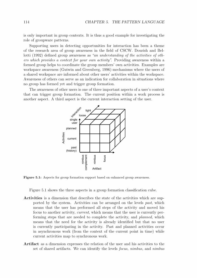
110 CHAPTER 4. APPROACH
Check. The transfer of the pattern to a concrete context requires that the developer(or the user) maps the abstract actors and relations named in the patternto his concrete application domain. To ease this process the check sectionprovides a list of questions that can be answered comparable to a checklist.The answers document the mapping between the application domain and thepattern domain.
– How are users represented in the application?
– Can the user representation be connected with a context-sensitive commandto add the user to a buddy list (and how)?
– How does a user select other users in the application?
– Where is the connection between selecting other users and looking them upin a list?
– Will the buddy lists be bound to a specific context (i.e., will users use dif-ferent buddy lists if they interact with different communities)?
Danger Spots. This section elaborates problems that may occur when the patternis actually integrated in a system. It includes pitfalls or technical caveatsthat might hinder the inexperienced developer from successfully applying thepattern.
If users only consider buddy lists for maintaining contacts to other users they
will hardly find new users in the system. Thus, you should ensure that users
can also browse other users who are not on their buddy list (e.g. by providing a
User Gallery→197).
Known uses. The known uses section is the second part of the pattern’s proof.It provides examples of systems that implement the pattern. The authors ofpatterns should try to find at least two examples from different groups (or,even better, other problem domains). The example shown below lists only oneof several known uses of the Buddy List pattern.
Instant Messaging Systems like MSN Messenger, icq, AIM, or Jabber allprovide buddy lists. Presence information is retrieved from the presenceserver only for those users, who are on the buddy list.Figure 4.6 shows how a contact can be added during a conversation with iqc.If the local user allowed other users to contact him, they can directly talkto the local user by sending him a message. Note that the remote user hasto retrieve the address of the local user by other means than the buddy listsince the local user is not yet on the remote user’s buddy list. The remoteuser will be shown as a user “Not in List” (cf. fig. 4.6-A) on the buddy listfor the time of the chat. If the local user feels that the contact is valuable,he can add the remote user to the buddy list by pressing the “Add” button,which will open the “Add User” dialog (cf. fig. 4.6-B). The local user canprovide a nickname for the remote user under which the remote user willappear in his buddy list. Note that the the “Add User” dialog by defaultchecks an option so that the remote user will be able to add the local userto his buddy list as well. This is important to maintain Reciprocity
→238
although it can be bypassed (by unchecking this option).

4.2. THE PATTERN REPRESENTATION 111
Figure 4.6: Adding a contact to the buddy list in icq.
From then on, the remote user will be shown on the buddy list with hiscurrent status (fig. 4.6-C). The local user can from then on get in contactwith the remote user easily without looking up this user’s icq number.
Related patterns. Lists patterns that should also be considered when the readerfinds the current pattern relevant. This section links to other patterns in thelarger context of the pattern language. For each related pattern it explainshow the pattern is related and how the patterns differ.
User Gallery→197 provides means for browsing all users in the system. As
outlined in the safety rules, a User Gallery complements a Buddy List
and opens the opportunity to meet new community members.
Reciprocity→238
is important if buddy lists reveal much personal information.In this case, a user should be able to control who can put the user on hisbuddy list. On the other hand, if the local user adds a remote user to hisbuddy list, the remote user should also be allowed to add the local user tohis buddy list.3
The main difference to PLML is that our pattern format provides a more detailedstructure of each pattern. This allows the user to selectively read only specific partsof the pattern regarding his current situation. While PLML distinguishes betweensolution and rationale, we argue that the pattern should provide more details sectionsfor the solution. Examples are the check section or the danger spots. Representing
3The original Buddy List pattern contains additional references to additional patterns.
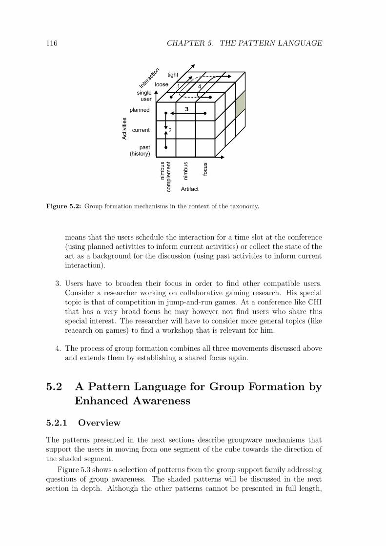
112 CHAPTER 4. APPROACH
a pattern from the groupware pattern collection by PLML would mean that thesections solution, collaborations, check, and safety rules need to be part of thesolution tag of PLML.
4.2.2 Pattern Abstraction Scale
Throughout all iterations the users participate and work with a shared groupwarepattern language. This language consists of patterns on different levels of abstrac-tion. High-level patterns describe issues and solutions typically targeted at end-users. Low-level patterns describe issues and solutions typically targeted at softwaredevelopers on a more technical level.
High-level patterns focus on the system behavior as it is perceived by the end-user. They empower the end-user to shape his software system to meet his demands.Thus, high level patterns need to be more descriptive and prosaic than low levelpatterns that focus on how to implement that behavior. Low level patterns focuson the implementation of the system and thus include more technical details.
Both low-level and high-level patterns can be positioned on a seamless abstrac-tion scale. This scale can be used to compare two patterns. Given two patternsp1 and p2, we can say that p1 < p2 if p1 focuses on more technical issues than p2
and uses a more developer-centered description language than p2. Note that theorder will not be a complete order. It is rather relative with respect to the currentfocus of analysis. The goal of the abstraction scale is to provide the reader witha first impression, e.g., whether or not the pattern requires software developers toimplement the solution.
Software design patterns that deal with class structures, control flow, or codingtechniques form the lower bound on the abstraction scale of patterns. Patterns thatfocus on human interaction and address computer systems just as tools to supportthe human interaction (e.g. groupware patterns) would be placed near the upperbound on the abstraction scale. Patterns at a very high level would describe how theend-user can compose off-the-shelf components and embed them in his work process.This would then mean that the software developer would no longer need to assistthe end-user in implementing the pattern.
Additional techniques for structuring pattern languages and supporting thereader and the author in orienting in the pattern language are discussed in appendixB.
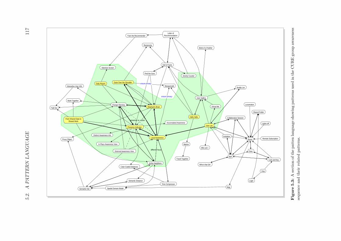
Chapter 5
The Pattern Language
Patterns are the most important tool of OSDP. The groupware pattern languagecurrently contains 130 patterns. Since it is intended as an evolving language, thepatterns are at different levels of completeness and the different topics of groupwaredevelopment are covered to a different degree. The pattern development was guidedby the users of the pattern language.
For space reasons, we will not present the full pattern language. We will insteadfocus on one aspect of the pattern language that is very characteristic for the de-velopment of groupware applications: group formation by means of enhanced groupawareness.
We will first discuss why this family is important for groupware developmentand provide a theoretic background on group formation issues (section 5.1). Section5.2.1 will provide an overview of the presented pattern language. The followingsections provide the full descriptions of eight patterns from the selected family. Shortversions of the other patterns from the groupware pattern language can be found inthe appendix. Note that the full catalogue of groupware patterns is scheduled forpublication at the end of 2006. More details on this can be found on the authors’home page http://www.pi6.fernuni-hagen.de/p4cmi.
5.1 Importance of Group Formation
In line with Heidegger’s concept of situatedness we can state that group interactionevolves out of a current social situation. The need for starting a group life cycle isdriven by the context of each prospective group member. However, if the users workin single-user modes, they often do not notice opportunities or needs for interaction.
The question to answer when forming a group is whether or not the currentsituation fits the need for collaboration between users. This question addresses tem-poral issues (when is the right point in time) as well as situational issues (what is theright work context to shift users’ attention to the process of group formation). Whilemany aspects of tool support in collaborative applications have their counterpart insingle-user applications (e.g., a collaborative diagram editor provides the same toolsfor manipulating diagram elements as a single user diagram editor) group formation
113

114 CHAPTER 5. THE PATTERN LANGUAGE
is only important in group contexts. It is thus a good example for investigating therole of groupware patterns.
Supporting users in detecting opportunities for interaction has been a themeof the research area of group awareness in the field of CSCW. Dourish and Bel-lotti (1992) defined group awareness as “an understanding of the activities of oth-ers which provides a context for your own activity”. Providing awareness within aformed group helps to coordinate the group members’ own activities. Examples areworkspace awareness (Gutwin and Greenberg, 1996) mechanisms where the users ofa shared workspace are informed about other users’ activities within the workspace.Awareness of others can serve as an indication for collaboration in situations whereno group has formed yet and trigger group formation.
The awareness of other users is one of three important aspects of a user’s contextthat can trigger group formation. The current position within a work process isanother aspect. A third aspect is the current interaction setting of the user.
Figure 5.1: Aspects for group formation support based on enhanced group awareness.
Figure 5.1 shows the three aspects in a group formation classification cube.
Activities is a dimension that describes the state of the activities which are sup-ported by the system. Activities can be arranged on the levels past, whichmeans that the user has performed all steps of the activity and moved hisfocus to another activity, current, which means that the user is currently per-forming steps that are needed to complete the activity, and planned, whichmeans that the need for the activity is already identified but that no useris currently participating in the activity. Past and planned activities occurin asynchronous work (from the context of the current point in time) whilecurrent activities map to synchronous work.
Artifact as a dimension expresses the relation of the user and his activities to theset of shared artifacts. We can identify the levels focus, nimbus, and nimbus

5.1. IMPORTANCE OF GROUP FORMATION 115
complement. The focus represents the set of artifacts that are in the focusof the activity. An artifact is in the focus if it is perceived and/or modifiedby the user in the activity. The nimbus contains artifacts that are closelyrelated to the artifacts in focus. Finally, the nimbus complement containsartifacts that are not part of the nimbus. These are artifacts that have a longsemantic distance to the focal artifact. The model of focus and nimbus hasbeen discussed in depth by Rodden (1996) although the nimbus complementwas not considered by Rodden.
Nevertheless, the nimbus complement is relevant for situations where activitieson complementing artifacts are an indication for group formation or awarenessinformation. If, for instance, the community could benefit from a shared un-derstanding of the full artifact space, users should especially be made awareof artifacts in their nimbus complement.
Interaction, finally, is the dimension that defines how tight two people currentlywork together. Users can work in a single-user mode without explicitly takingother user’s activities into account. The actions of other users are recognizedonly by changes in the shared data. Loose interaction focuses on the provisionof awareness about other users. Users still perform the activities as individualsbut are informed of other user’s activities. Thus although no direct interac-tion between the users takes place, there is an understanding of other usersin the system. Tight interaction focuses on how collaboration can be sup-ported between users. Manipulation of shared artifacts is only one issue inthis context. Other important issue are the awareness of other group membersin the workspace (workspace awareness (Gutwin and Greenberg, 1997)) andthe awareness of the group process.
The effects of group formation can be illustrated using the classification cube.Group formation mechanisms help the group to change their work context from onesegment of the cube to another (fig. 5.2). The closest form of collaboration takesplace in the shaded segment of fig. 5.2. In this case, users interact in a group at thesame time with a shared focus on the artifacts.
In general, we can distinguish four directions that should be considered in agroup formation process (represented by the numbered arrows in fig. 5.2).
1. Users move their focus from single-user human-computer-interaction to tightgroup interaction. Consider as an example a workshop at a conference. Po-tential participants prepare position statements (single user interaction) andpublish their position statements on a web server. Other interested partici-pants become aware of the position statements and review the collection ofposition statements (loose interaction). Finally, interested users register forthe workshop and meet in a meeting room to discuss the position statements(tight interaction).
2. Users narrow their corridor in time so that asynchronous interaction raisesthe need for synchronous interaction. For the example of the workshop, this

116 CHAPTER 5. THE PATTERN LANGUAGE
Figure 5.2: Group formation mechanisms in the context of the taxonomy.
means that the users schedule the interaction for a time slot at the conference(using planned activities to inform current activities) or collect the state of theart as a background for the discussion (using past activities to inform currentinteraction).
3. Users have to broaden their focus in order to find other compatible users.Consider a researcher working on collaborative gaming research. His specialtopic is that of competition in jump-and-run games. At a conference like CHIthat has a very broad focus he may however not find users who share thisspecial interest. The researcher will have to consider more general topics (likereaearch on games) to find a workshop that is relevant for him.
4. The process of group formation combines all three movements discussed aboveand extends them by establishing a shared focus again.
5.2 A Pattern Language for Group Formation by
Enhanced Awareness
5.2.1 Overview
The patterns presented in the next sections describe groupware mechanisms thatsupport the users in moving from one segment of the cube towards the direction ofthe shaded segment.
Figure 5.3 shows a selection of patterns from the group support family addressingquestions of group awareness. The shaded patterns will be discussed in the nextsection in depth. Although the other patterns cannot be presented in full length,

5.2
.A
PA
TT
ER
NLA
NG
UA
GE
117
different focus
presence vs. action
ensure privacy
ensure privacy
Change Warning
Local Awareness
Time Compressor
Virtual Me
Collaborative Session
Room
Semantic Distance
Birds of a Feather
Gaze Over the Shoulder
Presence Indicator
Find the Guru
Login
In-Place Awareness View
User List
Activity Counter
Visa
Active Neighbors
Buddy List
Bell
Map
Who am I
Travel Together
Who's that Girl
Proxy Object
Hello Hello
Door
Letter of Recommendation
Spatial Domain Model
Invitation
Masquerade
Remote Subscription
Lock and Key
Distinct Awareness Info
Mentor
Train the Recommender
Accumulated Awareness
Elephant's Brain
User Gallery
Reciprocity
Color-Coded Distances
Hall of Fame
Daily Report
Semantic Net
Lights off
Shared Folder
External Awareness View
Interactive User Info
Attention Screen
Locomotion
From Shared Data to Shared Work
Talk first
Work Together
Fig
ure
5.3
:A
sect
ion
ofth
epatt
enla
nguage
show
ing
patt
ernsuse
din
the
CU
RE
gro
up
aware
nes
s
sequen
ceand
thei
rre
late
dpatt
erns.

118 CHAPTER 5. THE PATTERN LANGUAGE
the overview allows us to catch a glimpse of the connectivity and complexity thatwe will find in a full-fledged pattern language for groupware development.
Activitie
s
Inte
ract
ion
Artifact
planned
current
past(history)
focu
s
nim
bu
s
nim
bu
sco
mp
lem
en
t
tight
loose
singleuser
Activitie
s
Inte
ract
ion
Artifact
planned
current
past(history)
focu
s
nim
bu
s
nim
bu
sco
mp
lem
en
t
tight
loose
singleuser
Activitie
s
Inte
ract
ion
Artifact
planned
current
past(history)
focu
s
nim
bu
s
nim
bu
sco
mp
lem
en
t
tight
loose
singleuser
Activitie
s
Inte
ract
ion
Artifact
planned
current
past(history)
focu
s
nim
bu
s
nim
bu
sco
mp
lem
en
t
tight
loose
singleuser
Activitie
s
Inte
ract
ion
Artifact
planned
current
past(history)
focu
s
nim
bu
s
nim
bu
sco
mp
lem
en
t
tight
loose
singleuser
Activitie
s
Inte
ract
ion
Artifact
planned
current
past(history)
focu
s
nim
bu
s
nim
bu
sco
mp
lem
en
t
tight
loose
singleuser
Activitie
s
Inte
ract
ion
Artifact
planned
current
past(history)
focu
s
nim
bu
s
nim
bu
sco
mp
lem
en
t
tight
loose
singleuser
(1)
(4)
(7)
(3)
(6)
(2)
(5)
Figure 5.4: Transitions supported by the patterns presented in this chapter (numbers link to the
pattern description in the text).
We can relate the patterns to the transitions shown in fig. 5.4. The patternsincluded in full length are:
From Shared Data to Shared Work→120
: Foster group formation and spon-taneous collaboration by bringing together users who share an interest in thesame data and providing them with means for communication and collabora-tion.

5.2. A PATTERN LANGUAGE 119
Users focus on an artifact in single user hci. They become aware of other userswho work at the same artifact at the same time and start tight interaction(fig. 5.4-1).
Local Awareness→127
: Provide awareness information in the context of the arti-fact, which is in the local user’s focus.
The pattern describes how to move from single user interaction to loose inter-action (fig. 5.4-2).
Presence Indicator→135
: Indicate that remote users look at an artifact, which isvisible on the local user’s screen.
The pattern helps to move from single user hci to loose interaction (fig. 5.4-2).
User List→141
: Show who is currently participating in a session.
This pattern focuses on tight interaction. Users should stay aware of collabo-rating users in the same session (fig. 5.4-3).
Gaze Over the Shoulder→145
: Detect the users’ interaction with shared arti-facts.
The focus of this low-level pattern is detect current activities. It is essential forproviding any awareness on activities (fig. 5.4-4).
Elephant’s Brain→150
: Store information on the users’ activities in a log to allowthe users to understand (other) users’ activities and the artifacts’ evolution.
This low-level pattern supports to move from past to current activities. Userswho are currently active can become aware of past activities, understand theirwork, and establish contacts (fig. 5.4-5).
Daily Report→158
: Inform the user about changes on relevant artifacts in a userdefined frequency (e.g., once a day).
This pattern is a high-level counterpart to the Elephant’s Brain pattern.It informs the local user about other users’ past activities on relevant focalartifacts (fig. 5.4-6).
Hello Hello→163
: List new members of a group or a community at a prominentplace and introduce them to other members.
One aspect of the Hello Hello pattern is that users move their focus fromthe focal artifact to the nimbus complement in order to become aware of othernew users who have not yet established contacts for loose or tight interaction(fig. 5.4-7).
The remainder of this section will present the individual patterns in their full form.
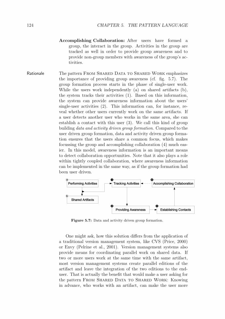
120 CHAPTER 5. THE PATTERN LANGUAGE
5.2.2 From Shared Data to Shared Work
Foster group formation and spontaneous collaboration by bringingIntent
together users who share an interest in the same data and providingthem with means for communication and collaboration.
Users are working with an application that provides access to sharedContext
data. They consume or manipulate the shared data using theirpersonal clients, which may be at diverse locations.
The shared data may be, for instance, a file, a set of files thatare used for a project, a cluster of related objects in a distributedapplication, or a set of records in a database that is accessed by allusers.
The interaction with the shared data is not easily predictable,since the possible activities do not follow a fixed set of workflows.
� � �
Although many users work with the same shared data,Problem
they may not recognize the other users’ work. This resultsin parallel or conflicting work and a lack of collaborationand learning from one another.
Imagine a scenario in the automobile industry: Many employeesScenario
work on the design of new car. Some experts design the electronics,while others work on the layout of the control panel. In each groupthere are different responsibilities and roles. While the designerarranges the tachometer, the ecologist considers how the tachometermay be recycled. All engaged employees work on the same shareddata – namely the design documents of the whole car.
During the design process different modes of collaboration(Schummer and Haake, 2001) may take place: First the designerworks on his own to create a first draft. If the material for thetachometer is to be specified, the situation demands a close co-operation with the ecologist. But the ecologist is not the onlyperson the designer needs to collaborate with. Together with a

5.2. A PATTERN LANGUAGE 121
mechanic, he has to investigate, whether or not the tachometer canbe created with the material considered. These are only two ex-amples of collaboration on shared artifacts, which is needed in acomplex design process.
The more complex and dynamic the environment (respectivelythe shared data) gets, the harder it is to predict all valuable con-stellations for collaboration by means of a strict work flow.
Consider as a less obvious situation in the car example the designof safety seats for babies and the development of an airbag securitysystem. In most modern cars that have a co-driver airbag, onecan no longer place the safety seat for babies on this seat since theinflation of the airbag may kill the baby sitting in the safety seat.In this example, two designers did not collaborate although theyworked with the same space in the car. The result is that somerequirements were not communicated among the two designers.
The examples show that collaboration opportunities are oftennot recognized and collaboration does not take place. This mayhave two consequences. The most obvious consequence is that thework of the different participants will result in conflicts. If thedesigner does not contact the electrical engineer and the mechanicalengineer, it might be that the design of the tachometer does notprovide any space for the needed cables that lead the signals tothe device. In this case, the designer obviously didn’t know muchabout the technical constraints of his design, which leads to thesecond consequence: The designer would not be able to learn fromthe electrical engineer. If they had collaborated, they could havediscussed their different experiences and won new insights.
From this scenario, one can see that it can be very importantto foster collaboration, when two or more users work on the samepart of the shared data.
You should consider to apply the pattern when . . .Symptoms
– managers consider it as difficult to predict who should collab-orate to reach a specific goal.
– team members notice that they worked on the same artifactsafter the work is finished.
– parallel work causes conflicts that could have been resolvedwhen the team members had worked together.
Users are unaware of the potential for collaborative activitiesthat could improve the overall result or minimize conflicting work.
The users are working with the shared data without muchknowledge of their colleagues (fig. 5.5 shows the user as box (a)who accesses shared artifacts (box b)). The only effect that lets

122 CHAPTER 5. THE PATTERN LANGUAGE
Figure 5.5: Single user’s work on shared data.
them deduce that other users are working on the shared data isthat the data changes from time to time. Uncoordinated collabo-ration in a shared filesystem is an example of this kind of work.
One of the forces in the context section stated that it is difficultto know all useful points of collaboration in advance. But evenif this knowledge exists, it is still challenging to establish groups.Users have to coordinate collaborative episodes before they actuallytake place (cf. fig. 5.6).
1
23
4
Figure 5.6: User driven group formation.
First, the users have to identify other users who should be partof the team and contact them to propose a collaborative session(cf. fig. 5.6-1). We call this kind of group formation as user drivengroup formation. If all participants agree, they start a collaborativesession (fig. 5.6-2). The topic of the session sets a new focus –the group focus – that all participants need to share. Establishinggroup focus may be difficult if the group members were focussingon unrelated activities when the group started its session.
Depending on the desired strength of collaboration, group mem-bers need to be aware of each other’s activities during the collabo-rative session. The users’ activities need to be tracked (fig. 5.6-3)to provide awareness (fig. 5.6-4). Awareness information is mainlyused to coordinate the activities in the collaborative session and toavoid conflicting activities in the same workspace.
Therefore: Model dynamic groups that are built from theSolution
set of users of the shared data who share a common interest(e.g. detected by patterns Local Awareness
→127or Change

5.2. A PATTERN LANGUAGE 123
Warning→228
).
Allow these groups to be established on the basis oftheir members’ activities (again Local Awareness
→127), so
that they are likely to have a common interest. Providethem with collaborative tools that support communication(Talk first
→242) and collaboration (like shared editing in a
Room→182
).
Use the patterns of the related patterns section to detaileach of the actions proposed by the above paragraphs.
Collaborations User: The user works with an application on shared data. His workinitially takes place in a single user mode. After becomingaware of other users, he starts a group with these users toenter closer collaboration.
Activity: Activities are objectifications of the actions the user per-forms. They represent a semantic entity formed of low-levelinteractions, such as key-strokes or mouse movements. Exam-ples for activities could be
– navigating from one web page to another,
– performing a search query,
– working in the same shared space (and in this case inter-preting the content of the shared space as shared data),or
– changing a method of a source file in a programming en-vironment.
As the examples suggest, activities should be at a semanticlevel, which make sense for the end-user.
Artifact: A set of artifacts represents the shared data. Activitiesfocus on artifacts.
Group: When users decide to collaborate, they form a group. Thisgroup then interacts using shared tools.
The participants (User, Activity, Artifact, and Group) collaboratein four main use cases that are addressed by related patterns:
Tracking Activities: Users perform activities on artifacts, whichhave to be tracked to be able to provide awareness (Gaze
Over the Shoulder→145
).
Providing Awareness: Based on tracked activities, the systemcalculates awareness information, which is indicated to users(Local Awareness
→127, Change Warning
→228).
Establishing Contacts: Users perceive awareness information.This means that they know, which other users they can con-tact to form a group (Talk first
→242).

124 CHAPTER 5. THE PATTERN LANGUAGE
Accomplishing Collaboration: After users have formed agroup, the interact in the group. Activities in the group aretracked as well in order to provide group awareness and toprovide non-group members with awareness of the group’s ac-tivities.
The pattern From Shared Data to Shared Work emphasizesRationale
the importance of providing group awareness (cf. fig. 5.7). Thegroup formation process starts in the phase of single-user work.While the users work independently (a) on shared artifacts (b),the system tracks their activities (1). Based on this information,the system can provide awareness information about the users’single-user activities (2). This information can, for instance, re-veal whether other users currently work on the same artifacts. Ifa user detects another user who works in the same area, she canestablish a contact with this user (3). We call this kind of groupbuilding data and activity driven group formation. Compared to theuser driven group formation, data and activity driven group forma-tion ensures that the users share a common focus, which makesfocussing the group and accomplishing collaboration (4) much eas-ier. In this model, awareness information is an important meansto detect collaboration opportunities. Note that it also plays a rolewithin tightly coupled collaboration, where awareness informationcan be implemented in the same way, as if the group formation hadbeen user driven.
Figure 5.7: Data and activity driven group formation.
One might ask, how this solution differs from the application ofa traditional version management system, like CVS (Price, 2000)or Envy (Pelrine et al., 2001). Version management systems alsoprovide means for coordinating parallel work on shared data. Iftwo or more users work at the same time with the same artifact,most version management systems create parallel editions of theartifact and leave the integration of the two editions to the end-user. That is actually the benefit that would make a user asking forthe pattern From Shared Data to Shared Work: Knowingin advance, who works with an artifact, can make the user more
5.2. A PATTERN LANGUAGE 125
cautious because he knows that all work that he does may conflictwith other users’ work. Collaboration at this point in time combinesthe integration aspect with the actual work – and puts the effortsfor integration on the shoulders of all co-workers.
Before applying this pattern, you should answer these questions:Check
– What are the artifacts that are used by more than one user?
– What concurrent activities do take place and what effect dothese activities have on the artifacts?
– Are there any pre-defined groups to which the activity trackingshould be limited? If yes, how will conflicts be resolved thatwere caused by concurrent groups?
– What kind of awareness visualization will you apply (cf. therelated patterns section)?
– Is there already a mechanism that tracks activities or do youhave to build such a mechanism?
– Do users agree that their activities are tracked? What happensif a user requests not to be tracked?
Providing mechanisms for dynamic artifact-based group formationDanger
Spots may lead to a practice that disregards formal team management atall. The pattern does not intend that formal work flows should bediscarded, but that they need to be accompanied by dynamic groupformation.
When designing the systems, you should take into account thatusers are often reluctant to change their current work environment.Thus, it is likely that totally new applications will not be used onlyfor the sake of better group awareness (cf. e.g. (Sohlenkamp et al.,2000)). You should integrate the group awareness and team forma-tion mechanisms as tightly as possible. The ideal case would notrequire any user actions for setting up the service, and users wouldonly notice the changed application, when collaboration opportu-nities arose.
Known
Uses
TUKAN (Schummer and Schummer, 2001) is a collaborative pro-gramming environment, which supports dynamic groups ineXtreme Programming.
A typical development cycle starts in a single user mode (orwith two developers working together at one machine). Thedeveloper selects an appropriate task and starts coding, asif he was working alone. At the same time, other develop-ers also start their work. All parties ignore one another untilthey become aware of each other because they are browsingor changing semantically related methods. The developers use
126 CHAPTER 5. THE PATTERN LANGUAGE
the built-in communication support to get in contact with eachother and finally decide that they should solve those parts ofthe task together that affect both of them. The system pro-vides means for synchronous collaboration such as a collabo-rative code editor.
I2I (Bradshaw et al., 2002) is a system that providesawareness on other users’ activities on the web.Whenever two or more users browse the same or a se-mantically related artifact, the system visualizes this as aPresence Indicator
→135. Users are provided with means
for communication to establish contacts to users working onrelated artifacts (Talk first
→242).
GAMA Mall (Schummer, 2002) is a design study of a collabora-tive shopping application, which extends the web pages of theAmazon.comTM bookstore. Users become aware of other usersbrowsing the store. The system informs the users if otherusers browse content, which is semantically relevant to the lo-cal user. Users can then initiate tighter collaboration, such aschatting or collaborative browsing.
� � �
Related patterns are grouped into four sections: patterns for pro-Related
Patterns viding awareness, patterns for tracking activities, patterns for es-tablishing contacts, and patterns for accomplishing collaboration.
You should first look at the pattern Local Awareness→127
.This pattern outlines the most basic way of providing awareness tousers of a system with shared data. It can be refined by extend-ing the notion of locality. The pattern Active Neighbors
→225
provides a starting point for this.
All patterns that aim on the provision of awareness rely on otherpatterns, which track the required data from the user actions. Thestarting pattern for this section is Gaze Over the Shoulder
→145.
If you feel that the application provides enough awareness, youcan figure out how contact is established (cf. Talk first
→242) and
which means you may use to support collaborative episodes (cf.Collaborative Session
→228).
The Pattern Adhoc Meeting (Coldeway, 2003) describes, howpeople should meet dynamically whenever an important issue arises.Although it does not relate to any technical issues or distributedteam settings, it shares the same idea.
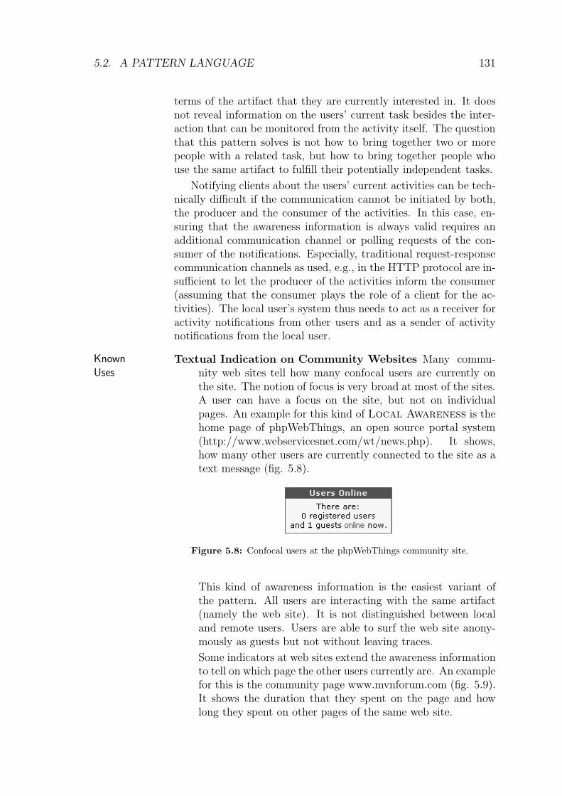
5.2. A PATTERN LANGUAGE 127
5.2.3 Local Awareness
Alternative name(s): Contextual Awareness, DocumentAwareness (e.g. (Cohen et al., 2000))
Provide awareness information in the context of the artifact, whichIntent
is in the local user’s focus.
Many users are working on a set of shared artifacts. You have al-Context
ready decided to use the pattern From Shared Data to Shared
Work→120
to encourage the formation of dynamic teams. Thegroups should be focussed on a shared current interest, whichmatches their current actions.
The application, which is used to access the shared data providesmeans for manipulating or accessing the data and for keeping itconsistent only.
The users’ current state is not yet reflected in the user interface.Especially, there is no means to find out whether or not other usersare available who share a common interest.
� � �
Although most systems that work on shared data provideProblem
support for coordinating shared access, they often don’ttell the user, who is working on a specific artifact. Suchinformation is needed to establish ad-hoc teams that sharea common focus. Without such information, users assumeto work alone – and do not see the possibility or urge forcollaboration.
Imagine a real world plaza, where people meet for social interaction.Scenario
This plaza is popular, since it offers many services, such as cafes tohang around, notice boards where citizens of the community posttheir private adverts, and shops where one can buy, for instance,food or books. Since the plaza is crowded, it motivates talking orresting in the community.

128 CHAPTER 5. THE PATTERN LANGUAGE
Now consider a virtual community web site. It also offers bul-letin boards, chat-rooms, and links to virtual shops. All these fa-cilities are arranged on a central portal page. Although all com-munication means and services are available, the users often feelisolated at the portal page. The community web site looks as if nousers were using it and does not motivate people to rest and talkin the community. Especially, the users don’t see a way to meet bychance, which is one characteristic of a real-world plaza.
You should consider to apply the pattern when . . .Symptoms
– users cannot say, whether or not other users work with thesame artifacts.
– users always have the impression of being on their own.
The background of the problem lies in the different nature ofreal-world interaction and virtual interaction. If people interactwith real-world-artifacts, they have to be physically co-located withthis artifact. In the case where more than one user works withthe artifact, these users have to be co-located as well since all ofthem have to be co-located with the artifact. When users interactwith artifacts in a virtual space, co-presence is not needed sinceall interaction is computer-mediated (and thus can be performedby means of computer networks). The users still interact with andhave a relation to the artifact, but they don’t have to get in contactwith the other users anymore.
Therefore: Provide awareness in context. This means thatSolution
the system tells the local user, who else is currently inter-ested in the local user’s focussed artifact and what theydo with this artifact. Show this information whenever theartifact is shown on the screen. The information shouldcontain details about the user drawn from his user profile,the artifact, and details on the activity, which the user isperforming. Ensure that the information is always valid.
Collaborations Artifact: The unit of shared data, the users work on. The granu-larity of the artifacts has to be determined by the applicationdesigner. Examples are web sites, single pages of a web site, ormore application specific artifacts, such as classes and methodsin a programming environment.
Activity: The representation of a user’s interaction with theshared artifact. It may be a modifying activity such as chang-ing a web page or a reading activity, where the artifact isperceived by the user. In many contexts, it is not trivial todetect which activities take place. The Gaze Over the

5.2. A PATTERN LANGUAGE 129
Shoulder→145
pattern points out how activities can be de-tected.
Local User / Confocal Users: The local user interacts with thesystem and wants to get informed about confocal users whointeract with the system from a distant location. Two ormore users are considered as confocal, if their current fo-cus is on the same artifact. This term was chosen to clearlydistinguish between physically co-located users who work atthe same physical location and confocal users who work withthe same virtual artifact.
The set of confocal users of an artifact contains all users whohave started an activity with the artifact, which is not yetfinished. Several known uses don’t distinguish between localand remote users when looking for activities. This implies thatthe set of confocal users for a specific artifact that is currentlywatched by the local user always includes the local user. Notethat all users are local users at their machine. On the otherhand, making the distinction reduces awareness informationto awareness on remote users (only activities performed byremote users are considered).
Awareness Information: Awareness information represents thestatus of remote users and is displayed to the local user. Theinformation may be at different levels of detail. For a smallset of confocal users, it may provide information on the otheruser’s identity.
By explicitly telling the user that also other users are working withRationale
the artifacts (or more general, work at the same virtual location),these users get aware of each other, which is the basis for establish-ing contacts.
As with From Shared Data to Shared Work→120
, onemight ask how this solution differs from the application of a tra-ditional version management system. If the only goal would beto avoid other users from overwriting their colleagues work, thismight well be reached by using a version management system, whichavoids parallel work on the same artifact (locking) or highlightsconflicts before they can be committed to the version managementsystem (such as in CVS (Price, 2000)).
But the important point in this pattern is that the user getsaware of activities that currently take place on the artifact – notactivities that are completed, as it would be the case when a userdecided to check in a new version. This opens the opportunity tocollaborate within the activity or adapt the activity to the changedsituation as soon as possible.

130 CHAPTER 5. THE PATTERN LANGUAGE
Another difference to version management systems is that theLocal Awareness pattern considers a broader range of activities– not only modifying accesses like in version management systemsbut also reading accesses to the shared data.
Before applying this pattern, you should answer these questions:Check
– What artifacts do users use?
– Can you identify the artifacts at different levels of scale? If yes,what is the right level of scale for the awareness calculation?
– How do you store the activity information? Can you makeuse of a central activity database (e.g., an Elephant’s
Brain→150
)?
– Will you be informed when new activities take place or existingactivities terminate? If no, can you think of an implementa-tion of the Gaze Over the Shoulder
→145pattern in your
context?
– Are there situations in which Local Awareness should beturned off?
The granularity of artifacts and the size of the user communityDanger
Spots determines, whether or not users will be aware of one another.
If the system is very crowded (i.e. many users are working onasmall set of artifacts), then the number of confocal users will belarge at each point in time. Displaying all confocal users as dis-tinguishable persons may produce an information overload and dis-tract the local user from his task. In this case, it is better to simplytell that there are some or a specific number of confocal users with-out revealing their identity. On the other hand, displaying only theinformation that users are sharing a focus on the artifact withoutproviding numbers for the size of the crowd does not provide anyuseful information in this case. This indicator will always be active.
If the system provides access to many artifacts and the group ofusers is small, the probability that two users work on the same arti-fact will be very small. In this case, you can either reduce the gran-ularity of artifacts or apply the pattern Active Neighbors
→225,
which extends the presence to other semantically related artifacts.
An important issue for the acceptance of the pattern is trust andprivacy. User monitoring does only work if it is mutually acceptedby all participants. Otherwise, you will soon get the effect thatusers complain about being monitored or don’t use the awarenessfeatures anymore. The pattern Masquerade
→196addresses this
problem.
When using this pattern you should not mix up tasks and ac-tivities: This pattern does only propagate current foci of users in
5.2. A PATTERN LANGUAGE 131
terms of the artifact that they are currently interested in. It doesnot reveal information on the users’ current task besides the inter-action that can be monitored from the activity itself. The questionthat this pattern solves is not how to bring together two or morepeople with a related task, but how to bring together people whouse the same artifact to fulfill their potentially independent tasks.
Notifying clients about the users’ current activities can be tech-nically difficult if the communication cannot be initiated by both,the producer and the consumer of the activities. In this case, en-suring that the awareness information is always valid requires anadditional communication channel or polling requests of the con-sumer of the notifications. Especially, traditional request-responsecommunication channels as used, e.g., in the HTTP protocol are in-sufficient to let the producer of the activities inform the consumer(assuming that the consumer plays the role of a client for the ac-tivities). The local user’s system thus needs to act as a receiver foractivity notifications from other users and as a sender of activitynotifications from the local user.
Known
Uses
Textual Indication on Community Websites Many commu-nity web sites tell how many confocal users are currently onthe site. The notion of focus is very broad at most of the sites.A user can have a focus on the site, but not on individualpages. An example for this kind of Local Awareness is thehome page of phpWebThings, an open source portal system(http://www.webservicesnet.com/wt/news.php). It shows,how many other users are currently connected to the site as atext message (fig. 5.8).
Figure 5.8: Confocal users at the phpWebThings community site.
This kind of awareness information is the easiest variant ofthe pattern. All users are interacting with the same artifact(namely the web site). It is not distinguished between localand remote users. Users are able to surf the web site anony-mously as guests but not without leaving traces.
Some indicators at web sites extend the awareness informationto tell on which page the other users currently are. An examplefor this is the community page www.mvnforum.com (fig. 5.9).It shows the duration that they spent on the page and howlong they spent on other pages of the same web site.

132 CHAPTER 5. THE PATTERN LANGUAGE
Figure 5.9: Confocal users at the mvnForum community site
(http://www.mvnforum.com/mvnforum/listonlineusers).
Odigo (Odigo, 2001) is an instant messaging client, which tracksthe users while they are navigating the WWW. It shows con-focal users in an external view (fig. 5.10). The user can chosewhether he is interested in the current page or in the wholeweb site.
Figure 5.10: Odigo (Odigo, 2001) showing confocal users at
www.amazon.com.
CSCW3 The CSCW3 prototype (Gross, 1999) is a system thatshows for a given URL who else is browsing this URL. It is aspecial kind of browser that logs user activities and displaysconfocal users in an external window (fig. 5.11). The local usercan see, who is currently on the page and who has been on thepage recently. The latter is a behavior that goes beyond thepattern’s proposed functionality. It is described in the Time
Compressor→242
pattern.
CoCoBrowse (Ter Hofte et al., 1997) is a specialized browser,

5.2. A PATTERN LANGUAGE 133
Figure 5.11: The CSCW3 prototype (Gross, 1999).
which shows in an attached window who else is currently view-ing or editing a specific web page.
� � �
Related
PatternsGaze Over the Shoulder
→145tracks user activities. Informa-
tion on users’ activities is needed to calculate the set of con-focal users.
Time Compressor→242
: Use the time compressor pattern, whenusers don’t work at the same artifact at the same time andyou still want to bring together users who worked on the sameartifact successively.
Presence Indicator→135
: If screen space is limited, you can usea Presence Indicator
→135to present information on the
confocal users in an iconic representation that saves space.
Change Warning→228
: For simplicity reasons, the current pat-tern assumed that all activities have the same quality. Thisis not the case for systems where users can change artifacts.

134 CHAPTER 5. THE PATTERN LANGUAGE
In these systems, you should consider to highlight possiblyconflicting activities using the Change Warning
→228.
User List→141
: User Lists have been applied frequently inshared workspace systems. Although these lists have manycommonalities (the visualization can, for instance, be thesame), there is a crucial difference in the intent. A traditionalUser List intends to provide awareness on participants whohave already joined a collaborative session. Group formationis not a goal of User Lists.
Publisher-Subscriber (Buschmann et al., 1996) can be used tokeep the calculation up-to-date.

5.2. A PATTERN LANGUAGE 135
5.2.4 Presence Indicator
Indicate that remote users look at an artifact, which is visible onIntent
the local user’s screen.
You have generated awareness information on confocal users usingContext
the Local Awareness→127
pattern or on peripheral users with theActive Neighbors
→225pattern. You have also decided to use an
In-Place Awareness View→233
to ease the process of connect-ing awareness information with those artifacts that are affected bythe awareness information. This means that you are showing theawareness information in a close proximity to the original artifact’svisualization.
Now you are thinking about how to visualize the awareness in-formation gathered.
� � �
The In-Place Awareness View→233
makes it easy to connectProblem
other users’ activities with focussed artifacts. But the sur-rounding of the artifact provides only limited space forinformation. Awareness information thus competes withapplication data.
Think of several users who are looking for books in a virtual book-Scenario
store. They want to be aware of one another to discuss the books,if they are interested in the same book. The virtual bookstoreprovides Local Awareness
→127and Active Neighbors
→225to
calculate confocal users or users who work in a semantic nearnessof the displayed artifacts.
Figure 5.12 shows how awareness information was displayed onthe screen. The developers chose to provide the awareness infor-mation next to the artifact’s representation on the screen. Thisinformation can be found next to the mouse pointer in figure 5.12.
The explanations of the awareness information clutters thewhole page layout because it uses too many words. In addition,

136 CHAPTER 5. THE PATTERN LANGUAGE
Figure 5.12: Textual in-place visualization of confocal users in a virtual
bookstore.
the textual representation of the awareness information is not eas-ily distinguishable from the domain information (in this case theinformation on books). That makes the information hard to per-ceive and disturbs the user from his actual task (to look for books).
You should consider to apply the pattern when . . .Symptoms
– the available information channels to transmit information tothe user don’t have much more capacity than what is neededto transmit the shared data.
– in GUI systems there is not much space for showing infor-mation next to the artifact so that the awareness informationdestroys the screen layout.
– external awareness views, such as a Radar View→238
, do notwork because the artifacts cannot easily be described withouttheir original context. For that reason, users find it hard to as-sociate awareness information with the corresponding focussedartifact.
Therefore: Limit the size of the awareness information’sSolution
representation so that it uses only a small part of the
5.2. A PATTERN LANGUAGE 137
available information channels. For a GUI system, thismeans that you should represent the confocal or periph-eral users as a single icon instead of a long textual form.Focus on telling that there are other users, rather thanproviding much information on the other users’ identityor task. Ensure that the indicator differs from the otherartifacts representing application data.
The main participant of the pattern is the indicator, which repre-Collaborations
sents the awareness information. Each indicator displays awarenessinformation for activities of confocal users or active neighbors thatare referencing one specific artifact. The indicator is placed rightnext to this artifact. The indicator can be an icon in GUI systems,a special sound in audible interfaces, or any real-world object intangible interfaces. It should be distinctive from the application’sshared data.
Wherever possible, the indicator has built-in behavior, whichreveals more clues on the awareness information. For instance, iftool tips are available in the user interface, the indicator can explainitself with a tool tip when the mouse pointer touches it.
The sets of confocal users or active neighbors can be character-ized by different group aspects:
– the cardinality (i.e. the number of confocal or nearby users),
– the distance to the artifact (this is always 0 if the users are con-focal; for active neighbors, it represents the semantic distanceof the user to the artifact), and
– the users’ identities (which is uncomplicated if it is only oneconfocal user).
It is up to the application designer to map the different groupaspects to the indicator. In general, size, color, and shape can beused as dimensions to represent the above aspects.
A mapping function can – in most cases – automate the projec-tion of group aspects to the different dimensions of the indicator.
The indicator has two main advantages that help the user to noticeRationale
the awareness information without being disturbed by it: Firstly,it does not use much space (resp. bandwidth of the informationchannel) and therefore it can in most cases be integrated with therepresentation of the artifact. Secondly, the indicator is visual dif-ferent to the rest of the displayed information. By carefully keepingthe indicator distinguishable from the artifact’s visualization, userswill no longer mix the awareness information with the shared arti-facts.

138 CHAPTER 5. THE PATTERN LANGUAGE
Figure 5.13: Graphical in-place visualization of confocal users in a
virtual bookstore.
Figure 5.13 shows how the awareness information can be dis-played using presence indicators. In this design, only one aspect ofthe confocal user group is reflected in the icon (next to the cursorin figure 5.13): the color represents the distance of the user (or theuser’s) to the artifact. In the above case, red (dark) icons representusers who browse very related books whereas green (light) iconsrepresent users who browse more different books.
By placing the icon next to the artifact one directly connectsusers to artifacts. Especially in settings where the users do notcollaborate in the same workspace this is the only reference pointfor collaborative activities. This gets even more important if oneaddresses the asynchronous case (as stated by Dourish (1997)).
Before applying this pattern, you should answer these questions:Check
– What is the focus of the visualization? Is it to represent usersor to provide awareness on activities?
– What icon shape best represents the (groups of) users?
– Is cardinality of users/activities important? If yes, can youvary the size, the color, or the brightness of the icon?
– Are there different levels of importance for different activitiesor users? If yes, can you reflect the importance of the most

5.2. A PATTERN LANGUAGE 139
important activities or users in the presence indicator’s coloror shape?
– Can you provide a tool-tip? If yes, what details will you showin the tool tip?
Ensure that the icon’s visualization does not conflict with otherDanger
Spots visual elements on the screen. Conflicting means in this contextthat the application itself uses icons of a comparable shape or color.Use a Distinct Awareness Info
→229in this case.
Known
Uses
TUKAN and GAMA-Mall both use little figures to representconfocal or nearby users. GAMA-Mall (Schummer, 2002) wasalready shown and discussed in the motivation and rationalesections of this pattern.
Figure 5.14: Presence indicators in the TUKAN team programming
environment.
The programming environment TUKAN (Schummer, 2001b)uses colored figures that are attached to methods to show thatother users are working on the same or related artifact (fig.5.14).
PoliAwaC (Sohlenkamp et al., 2000) is an awareness client for thePoliTeam collaborative workspace application that was usedby members of the German government ministries in Berlinand Bonn. Members exchanged and organized documents us-ing PoliTeam, which were formerly circulated in folders (whenthe whole ministry was in Bonn).
In PoliAwaC, the users can browse shared artifacts using anexplorer-like view (fig. 5.15). If an artifact is currently viewedby another user, the artifact’s icon is changed: the size isenlarged to make these documents more prominent and partsof the icon are blended with a color that represents the userwho is currently viewing the artifact. A smily icon is finallyadded to the enlarged icon to visualize the process of viewing.
The system was evaluated in the ministry (on daily use) andthe awareness icons were regarded as useful. The only problem

140 CHAPTER 5. THE PATTERN LANGUAGE
Figure 5.15: Presence Indicators in the PoliAwaC awareness-client
(Sohlenkamp et al., 2000).
that users reported was the mapping between icon-color anduser color.
Flying flags as the one shown in the introductional picture arereal-world representations of presence indicators. Wheneverthe sovereign arrives at the castle they fly the flag. Thus,anyone can see whether or not it makes sense to go to thecastle and contact the sovereign.
� � �
Related
PatternsChange Warning
→228: When users manipulate the shared data,
it might be more important to report on other user’s mod-ifications to the shared data than reporting on other user’spresence. The Change Warning pattern does so, by indi-cating confocal modifications of other users.
Color-Coded Distances→228
can be used to visualize the factthat the presence indicator displays the presence of a user at arelated artifact and not at the artifact to which the indicatoris attached. Use this pattern if active neighbors should bedisplayed.
Interactive User Info→199
describes how to design the aware-ness info so that it can be used as a means for establishingcommunication or collaboration sessions.
Distinct Awareness Info→229
discusses how the visualizationcan be designed so that it does not disturb too much fromthe user’s current task.

5.2. A PATTERN LANGUAGE 141
5.2.5 User List
Show who is currently participating in a session.Intent
You have managed to establish a Collaborative Session→228
Context
between several users. These users start to interact. Now you arethinking about ways for communicating group membership aware-ness.
� � �
Users who only share common data have no mutual aware-Problem
ness of each other. Users don’t like to perform activities ifthey don’t know who observes them. Thus, they will notact freely with the shared artifacts.
Fred and Thelma frequently meet in the room at noon and startScenario
chatting about problems with an architecture they are currentlydesigning. They start to discuss about how to convince the leadarchitect Steven about necessary changes to his proposed architec-ture and at the same time avoid conflicts with Steven. However,Steven got conspicuous and entered the chat room at a quarter tonoon. Unfortunately, Fred and Thelma could not see that Stevenwas already there. The consequences are up to your imagination.
You should consider to apply the pattern when . . .Symptoms
– effective interaction requires that other users can be identified.
– session membership may change over time.
– not all users of a system collaborate in all sessions.
– distributed users cannot see one another.
– users frequently broadcast requests like“Hi, who else is presenthere?”.
Therefore: Show the names of all users who are in the sameSolution
session in a user list and ensure that the list is always valid.
142 CHAPTER 5. THE PATTERN LANGUAGE
The user’s name is added to the session’s user list as soon as heCollaborations
enters the session. The user list is a visual representation of allusers who are currently participating in the session. When a userleaves the session his visual representation is immediately removedfrom the user list. The user list acts as a subscriber that getsinformed whenever the underlying model (the set of participatingusers) changes, e.g., using the Publisher-Subscriber pattern.
By adding a user list, all participants can see who else is part ofRationale
the group. They can be sure that only the users on the user listcan see their activities. This is the first condition to establish trustin the group. If the local user trusts all other present users, he willact freely.
Before applying this pattern, you should answer these questions:Check
– What is the context of the User List? Does it make sense toshow a user list for the whole application or should you ratherdistinguish between session-centered user lists?
– How many users do you expect in your user list?
– Can you use graphical representations in the user list (Vir-
tual Me→197
)?
When the users enter the stage – namely that they perform anDanger
Spots activity in a shared workspace – the system adds them to the User
List. The users are removed when they leave the shared workspaceby moving on to another workspace. This works fine if all usersalways move between workspaces or explicitly log-off the system.But what happens if users simply switch off their computer or loosetheir network connection? Their user representation will be part ofthe User List forever. To detect wether a user is still availableuse timeouts for the execution time of a specific function or useserver-side or client-side mechanisms.
Not all visualizations of the user list do scale for large numbersof users. If you consider, e.g., to list all names in a text field, thenumber of users is limited by the length of all concatenated usernames, which is constrained by the length of the text field.
Known
UsesMSN Messenger shows a user list in each chat window. Each
user is shown with a user picture (cf. Virtual Me→197
). Incontrast to other systems it only shows remote users in theuser list (in the right middle of fig. 5.16). The local user isshown in a separate place (cf. Who am I
→191).
COAST (Schuckmann et al., 2000) generates user lists by visual-izing the set of interested users of a shared application model
5.2. A PATTERN LANGUAGE 143
Figure 5.16: A user list in the MSN Messenger.
(see fig. 5.17). Implementing a user list in COAST involvesthe following steps:
1. Select the local application model (e.g. ChatAppLocal) ofthe application that needs a user list.
2. Add a read-only COASTInputfield to the windowSpec us-ing the user interface builder.
3. Name the aspect for the input field userlistText.
4. Open a methodBrowser on the methodChatAppLocal>userListText (use the classnames ac-cording to your application model).
5. In the getValue-block retrieve the names of the intereste-dUsers for the sharedApplicationModel and combine theminto one string. The code may look like this:[userString := ’’.
self sharedApplicationModel interestedUsers
do: [:aUser| userString := userString, aUser name printString]
separatedBy: [ userString := userString, ’, ’].
userString].
6. Clear the setValue-block to ensure that no value can beassigned to the field.
UNIX who: The who command in Unix can be used to show allusers, who are connected to the same machine.
max% who
schuemme pts/2 Aug 4 10:59 (pd9e9c14c.dip0.t-ipconnect.de)

144 CHAPTER 5. THE PATTERN LANGUAGE
Figure 5.17: A COAST user list in the UML-Editor.
bourimi pts/3 Aug 4 11:02 (amsterdam.pi6.fernuni-hagen.de)
max%
Although the users do not necessarily collaborate, they sharethe same resources in their session.
� � �
Related
Patterns
Collaborative Session→228
and Room→182
: Sessions or roomsin most cases include a user list.
User Gallery→197
lists all users who are known by the systemregardless their current collaboration status.
Buddy List→227
limits the set of shown users to known users. Thisis especially useful if a large number of users share the samesession.
Local Awareness→127
shows the presence of users who focus on aspecific artifact. It provides detailed information regarding theusers’ interests (and often shows less users). The User List
instead shows all users who are in the same session, regardlessof the artifact that they are focussing on.
Virtual Me→197
supports users in generating an electronic repre-sentation of themselves. These representations can be used inthe user list to make the entries of the list more personal.
I Am Alive (Saridakis, 2003) requests the client to send notifica-tions showing that it is still available. If these notifications failto appear remove the corresponding user from the list.
Are You Alive (Saridakis, 2003) When using this pattern, thesites regularly check whether another site is available. If not,remove the corresponding user from the list.
Session Timeout (Sørensen, 2002) uses upper bounds for thetime in which a session object has to be accessed before it ismarked invalid. Similarly, one can use upper bounds for timebetween two activities of a user shown in the User List. Assoon as the upper bound is passed remove the correspondinguser from the list.
Publisher-Subscriber (Buschmann et al., 1996) can be used tokeep the calculation up-to-date.

5.2. A PATTERN LANGUAGE 145
5.2.6 Gaze Over the Shoulder
Alternative name(s): Event Sensors (Prinz, 1999)
Detect the users’ interaction with shared artifacts.Intent
Users interact with shared artifacts using proprietary tools andContext
want to log activities for future reference. The tools modify theshared artifacts. The results of the modifications are visible withinthe tools and in the changed shared arifacts.
� � �
Many proprietary tools are not designed for extendability.Problem
They do not provide means to modify the application’sbehavior. This makes it difficult to add automatic track-ing of user’s activities, which you would need to provideawareness.
Imagine a seminar where Alice, Jane, and Sally, a group of stu-Scenario
dents, are preparing a talk. They decided to do literature researchindependently using the web. Each of them signed up for a sectionof the topic and starts her search. After two weeks, they meet againand merge the results. Each of the students has written down someURLs, which she had rated relevant. During the discussion, Janenoticed that one of the pages found by Alice is very related to someinformation that she encountered during her research but did notrate relevant enough to add it to her URL list.
Unfortunately, she does no longer remember the URL of thatpage. Since remembering a page required that Jane actively set abookmark in her browser, she only did this for those pages that sheexpected to be relevant. This information was her final result of hersingle user task – namely the research in her section of the topic.
If she had also remembered the path that led her to the solution,her team mates could have benefited from this information. On theother hand, it would have been a large overhead to manually saveeach page.

146 CHAPTER 5. THE PATTERN LANGUAGE
Therefore: Add an additional layer in the communicationSolution
between the application and the shared data to monitoruser actions. Allow other parts of your application (e.g.a Elephant’s Brain
→150or a Local Awareness
→127) to sub-
scribe to monitored activities.
Collaborations Request: The user performs activities on shared data. Activitiesare internally represented as requests from a user interface el-ement (in the broadest sense) to a shared object. An examplefor a request could be the request to save a file in a text editor.
Listener: The listener observes the communication channel andthe shared object and forwards information on activities to asubscriber such as the Elephant’s Brain
→150. The listener
seems to be transparent. That means that the user (resp. thesource of the request) does not notice that the request passed alistener when it was transmitted via the communication chan-nel.
Communication Channel: Requests are transmitted using acommunication channel. To apply the pattern, one needs tobe able to monitor this communication channel.
Since the data is accessible by more than one user, there hasto be a communication channel by which the users access theshared data or by which they are informed about state changes.
All communication that takes place via this channel can bemonitored (if it is not encrypted) by the listener by either ob-serving state change that results from communication activityor by directly grabbing the information from the communica-tion channel.
In a point-to-point communication, this requires that the lis-tener acts as a man in the middle. It receives all requestsfrom the application and forwards these requests to the sharedobject (thereby playing the role of the original sender of therequest).
In a broadcast communication infrastructure, the listener canjust act like any other receiver (and listen for the same requestsas the intended receiver).
Where the communication channel is located depends on theapplication’s communication architecture:
– In WEB applications, it can be the TCP-connection thatis used to transfer HTTP requests. TCP connectionscan by definition have many intermediaries such as proxyhosts, routers, or gateways. To attach to this communi-cation channel, a listener could act as a proxy. It wouldperceive a user requesting an URL. On the other hand,

5.2. A PATTERN LANGUAGE 147
WEB applications model most interaction within URLs.The listener would in this case need to parse the URL (oreven the response as well) to retrieve more information onthe user’s activity.
– In applications that work with files on a shared file sys-tem, the communication channel is the file access API,which is often again a network protocol (e.g. in NFS (SunMicrosystems, 1989)).It can also be a state change in the file system that in-dicates that an activity takes place. If users, for in-stance, start working with a MS-Word document calledMyText.doc, MS-Word creates a temporary file named~$Text.doc, which contains, among others, informationon the user who opened the document. When the usercloses the document again, this file is removed.A listener would in this case monitor the directory, wherethe shared files reside and track the creation and the re-moval of temporary files. It would perceive
. a user starting to work with a document,
. the creation of a new version of the document, and
. a user ending his work with the document.
Since the proprietary tool does not allow other applications to en-Rationale
gage in the internal application logic, the only way to distributestate information is by observing external communication channels.
If the observer of the channel notices communication, it can re-distribute this information to subscribed users (using, for instance,a shared repository that holds information on all activities, such asthe Elephant’s Brain
→150). In this way, it is possible to calculate
awareness information without changing the original application.
Before applying this pattern, you should answer these questions:Check
– What is the communication channel in your application?
– Can you identify the user from messages observed at the com-munication channel? If yes, how is the user represented? Ifnot, could the application of the Who’s that Girl
→245pat-
tern help?
– Can you identify the accessed artifact from the observed com-munication? Is the identifier unique?
– Can you store the identifer directly in the activity or do youneed a Proxy Object
→237?
– Will you observe the communication channel or will you act asa man in the middle (i.e., as a proxy)? Will the communicationbe affected by the listener?

148 CHAPTER 5. THE PATTERN LANGUAGE
Ensure that the user knows that he is monitored. Users have toDanger
Spots be able to decide on their own whether or not they want to bemonitored (cf. Masquerade
→196). And they have to feel that
being monitored adds value to their activities (e.g. because of theprinciple of Reciprocity
→238). Otherwise, they will in most cases
find a way to do their job bypassing the monitoring mechanisms.
Known
Uses
NESSIE: The NESSIE framework (Prinz, 1999) provides eventsensors, which are comparable to the listener in this pattern.The sensors are placed next to specific artifacts. Whenever anactivity is performed on the artifact, the event sensors createan activity object, which is then stored in the NESSIE aware-ness server (see the description in Elephant’s Brain
→150).
User-Centered Push (UCP): Underwood et al. (1998) pro-posed an architecture that monitors the user’s interaction withthe WWW and makes this information available to other users.Listeners (called information sleuths) monitor TCP streamsthrough which a user accesses content on the web. When-ever content is accessed, information on this access (referredas fact) is sent to a shared access log (called board).
Proxy-Logger: The Proxy-Logger (Hong and Landay, 2001) isa web proxy, which tracks the user’s browsing activities tocreate diagrams that visualize the browsing actions involved ina specific task. The listener is modeled as a proxy. Users enterthe URL, which they want to visit, in the proxy’s welcomepage. The proxy then modifies all delivered HTML content,so that all subsequent URL’s are also retrieved by the proxy.
GAMA Mall (Schummer, 2001a) also uses a proxy approach tomonitor web browsing activities.
� � �
Related
Patterns
Elephant’s Brain→150
provides means for storing monitored ac-tivities.
Masquerade→196
provides the user with means to switch the mon-itoring mechanisms on and off.
Reciprocity→238
is an important issue when users are asked toprovide personal information. Make sure that the user per-ceives a personal benefit by providing personal information.
Proxy: The most obvious method for implementing the Gaze
over the Shoulder pattern is to use a Proxy pattern(Rohnert, 1995) in a way that the communication channelis redirected through the proxy. But the proxy approach isonly one possibility to keep track of actions. As discussed in

5.2. A PATTERN LANGUAGE 149
the participants section, there are different points where thelistener can be attached to the communication channel. Themost appropriate point depends on the nature of the commu-nication channel.
Navigation Observer (Rossi et al., 1995)solves a comparable problem in the context of hyperme-dia applications. As in Gaze over the Shoulder, actionsare recorded for future reference. The main difference is thatthe Navigation Observer implements a full Observer
pattern (Gamma et al., 1995) with the implication thatupdate messages are sent from within the application directlyto the observer. The application (i.e. the controller) thusneeds to know its observers, which are notified on statechanges. This is in conflict with one constraint of the Gaze
over the Shoulder’s problem: the application shouldnot be changed. The observation mechanism in Gaze over
the Shoulder is in contrast independent of notificationmechanisms of the observed application.

150 CHAPTER 5. THE PATTERN LANGUAGE
5.2.7 Elephant’s Brain
Alternative name(s): Event History, Activity Log
Store information on the users’ activities in a log to allow the usersIntent
to understand (other) users’ activities and the artifacts’ evolution.
Users perform parallel activities on shared artifacts without beingContext
totally sure about the effects. They tend to try out solutions with-out knowing whether or not the effects will be correct. Anotherissue is that they are not always able to tell which artifact they willuse for their activity, and often activities conflict with other users’activities.
Users work with the shared artifacts for a long time and it maybe necessary to review artifacts that were manipulated in a formerwork episode (e. g. the programming work of the previous week,month, etc.).
� � �
Merging two users’ (past or current) work is a difficultProblem
task. It requires that the activities are transferred to thesame context and that the goals are aligned. But manyapplications don’t provide access to the artifact’s history,its use, and its evolution. Thus, merging is vulnerable toerrors and often collaboration does not take place since themerging efforts exceeds the estimated gains of a collabora-tion.
Imagine a single user software development environment. TheScenario
programmer is developing an application using a development ap-proach, where testing and development are two alternating phases.She begins with writing a test for the desired functionality – as-sume that she is looking for an algorithm that calculates all primenumbers. In the test, she checks, whether the algorithm finds theprime numbers 3, 5, and 7.

5.2. A PATTERN LANGUAGE 151
She then continues to write software that fulfills the test - let’ssay that the algorithm just checks whether the number is largerthan 1 and odd.
In a next step, she creates a second test that ensures that 9 isnot a prime number. Writing code to pass the test brings her tothe idea of changing the code in a way that it checks whether thenumber is odd and between 3 and 7.
A next test demands to also accept 11 as a prime number. Atthis point, the programmer notices that the last change was not re-ally correct. Thus, she has to revert the change. But unfortunatelythe development environment does not support her. She has to re-member the change that she applied and try to recover the previouscode version from her memory. It may be simple if the action thatneeds to be reverted is the last action that she performed. Butoften one does not see the problems of a specific activity directlyafter the activity was performed. It is rather often the case thatone identifies the effects of wrong activities a long time after theactivity was performed.
Now consider a scenario where two programmers work on thesame project. Each programmer solves different problems, but bothproblems involve the same shared artifact. Even if the first pro-grammer does still remember which changes she performed, thesecond programmer cannot revert these activities, because he doesnot know what his colleague did.
You should consider to apply the pattern when . . .Symptoms
– users often notice that an artifact changed, but could no longerremember how it looked before.
– users cannot detect who performed incorrect changes, andwhat these changes were.
– users cannot find out what another user X did to the artifactY yesterday.
– users don’t understand the changes of other users.
Therefore: Remember all activities that users perform onSolution
shared artifacts – not only modifying accesses, but alsoread accesses. Provide access to the activities, so thata user can understand (and merge) other users’ activitieswith his own activities.
Two main participants are involved in the pattern: the log and theCollaborations
activity. A log is a container that holds the activities. Logs shouldbe persistent to allow the users to refer to activities of previoussessions.

152 CHAPTER 5. THE PATTERN LANGUAGE
The activity includes information on
– the type of the activity, such as reading, editing, creating,removing, etc.,
– the artifact that was touched by the activity (often in twoversions: the version before the activity and the version afterthe activity),
– the time at wich the activity took place (often as a set of twotimestamps representing the start and the end of the activity),and
– the user who performed the activity.
In several systems, activities further include a user comment, whichprovides more information on the activities intent. Activities shouldcomprise one semantic user transaction with the system. Examplescould be the selection of a menu command, the insertion of a newparagraph in a text document, or the viewing of a web page in aweb browser. Activities should be updated immediately when auser interacts with the application.
Clients interact with the log by adding and consuming or query-ing activities. The log should be accessible from all clients whoneed to perform calculations on it or who submit activities for logstorage. In collaborative applications this implies that it can beaccessed using a network protocol.
For the display of up-to-date collaboration information, thelog can serve as a Publisher of new activities according tothe Publisher-Subscriber pattern (Buschmann et al., 1996).Clients who use the log to provide awareness information, subscribeto activities. They provide an activity pattern that describes rele-vant activities. The publisher will inform the subscriber wheneveractivities matching the pattern change.
By logging all activities that users perform, one can inspect allRationale
activities later. This helps to understand the evolution of a specificartifact (by looking at all activities that took place on the artifact)or a specific user’s work (by looking up all activities, which wereinitiated by a specific user).
Since the log is persistent, the information will be rememberedalso when the user has forgotten it.
The Elephant’s Brain goes beyond version managementfunctionality in two main points:
1. It also remembers accesses that did not change the artifact.These accesses are not mandatory for restoring the system ata specific point of time. But they help to understand the user’s
5.2. A PATTERN LANGUAGE 153
background for a specific activity, and in some cases they helpto reveal conflicting activities.
2. The Elephant’s Brain provides means for notifying inter-ested users on activities, which take place with a specific ar-tifact (note that some version management systems supportthis, which is the reason why CVS is included in the knownuses section, although it does not remember non-modifyingaccesses as it was discussed in the previous paragraph).
Before applying this pattern, you should answer these questions:Check
– Do you have a central server component on which you canplace the log? If not, how do you distribute the logs betweenclients?
– Who will create the activity object, the client or the server?What information is needed to create and initialize the activityobject?
– What information will you transmit to the server if you gen-erate the activities at the clients?
– How do you support efficient queries of the activity log? Howdo you handle large numbers of activities? Can you use adatabase that to store the activities?
– Does it make sense in your context to create an activity logfor each artifact (i.e., store the activities together with theartifact)?
Ensure that many users can add activities to the log at the sameDanger
Spots time. One way for achieving this is to model the log as a bagto which users can add activities in any order producing the sameresult. Since each activity is unique (distinguishable user and time),there will be no conflicts in adding activities to the log.
When referencing artifacts in the activity description you haveto make sure that the right version of the artifact is referenced. Inenvironments, where no versioning is available, you should includesufficient information to restore all different versions of an artifactfrom inspecting all activities that took place on the artifact.
Prinz (1999) argues that the activity log should be decoupledfrom the application, which generates events. This allows an easyextension to support a large variety of events generated by differentclient applications.
Note that the Elephant’s Brain can only store those activ-ities that it gets informed of. For off the shelf tools like CADpackages, this might just be the creation of a new version. Youshould therefore carefully examine the application to monitor as
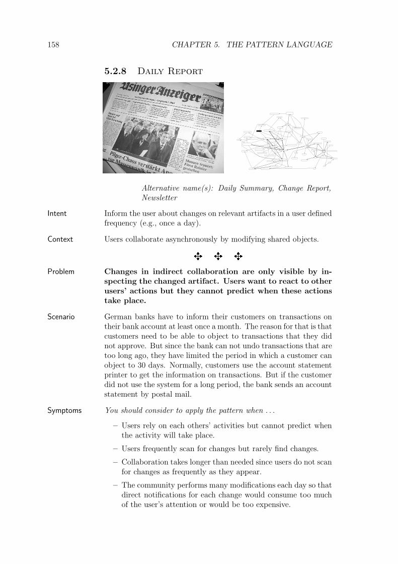
154 CHAPTER 5. THE PATTERN LANGUAGE
much information as possible since this information is crucial fora detailed (and intelligent) group support. Refer to Gaze Over
the Shoulder→145
for hints on how to gather such information.
Known
UsesCVS version logs: The CVS version management system
(Price, 2000) maintains a file history, where meta-information on all activities is stored. This information in-cludes the user, the touched artifact, and the type of the mod-ification. The version information can be obtained using thecvs history command. An example output looks like this:
cvs history -c
M 2003-02-27 13:09 schuemm 1.2 README test == ~test2\test
A 2003-02-27 13:14 schuemm 1.1 short.txt test == ~test2\test
M 2003-02-27 13:16 schuemm 1.2 short.txt test == ~test2\test
Each line in the history output describes one user action withinthe CVS repository. It shows a type-code of the activity, itstime, the user who performed the activity, and the artifactthat was modified.
One can configure a cvs server to run any software when arti-facts are accessed. This can be used to allow distributed clientsto subscribe to changes according to Elephant’s Brain. Asubscription mechanism as it was proposed by the Publisher-
Subscriber pattern, however, is not part of the standard cvssystem.
CVS only logs accesses to the repository. This is sufficientto support a Change Warning
→228. For the provision of a
Presence Indicator→135
, it is too few information. Pres-ence indicators would need information not only on those ac-tivities that were performed to copy shared artifacts to a localworkspace. It would also need the information on what theusers do in their private workspace.
VisualWorks Change Set: The VisualWorks Smalltalk environ-ment (Cincom, 2001) writes all changes to a change file. Thischange file is mainly intended to recover from system crashes,but an important additional use-case is the inspection of chan-ges of an artifact.
VisualWorks provides a special changes browser for this, whichshows all changes of a specific source artifact.
Since the programming environment is a single user environ-ment, it does not provide any multi-user access to the changefile.
NESSIE Awareness Server: The NESSIE Awareness Server(Prinz, 1999) is a general purpose awareness server, which

5.2. A PATTERN LANGUAGE 155
stores events. Each event carries information on the origi-nator, the action, the touched artifact, and the time at thatthe event took place. The events are implementations of Ele-
phant’s Brain’s activities.
Client applications can add activities to the server using anHTTP-based interface. They can also subscribe to changes byspecifying the type of the activity and a desired context (i.e.the touched artifact’s location).
BSCW (Bentley et al., 1997b) is a shared workspace system thatlogs all activities, such as reading, editing, or moving doc-uments, that are performed in the shared workspace. Thelogfile captures events that look like this:
User:[52, ’Alice’]
object:[134, ’Home’]
Type:CopyEvent
Time:1030181775.14
Path:[[63, ’&NewHome’]]
User:[51, ’Bob’]
object:[124, ’BusinessPlan.doc’]
Type:CutEvent
Time:1030182090.44
Path:[[119, ’Workgroup’]]
The example shows parts of two activities. First, a user Alicehas copied an artifact called Home to a folder NewHome. Inthe second activity, Bob cut the artifact BusinessPlan.doc.
TUKAN (Schummer and Schummer, 2001) is a collaborative pro-gramming environment that extends VisualWorks Smalltalk.It logs all activities that users perform in the environment (e.g.reading source code or modifying a class file) and stores theseactivities in an activity log.
The activity log is stored as a shared object, which is repli-cated to all clients using the COAST framework for syn-chronous groupware (Schummer et al., 2001). The replicationmechanisms also include a distributed version of Publisher-
Subscriber to trigger view updates or other actions whenany log entry changed.
� � �
Related
Patterns
Proxy Object→237
: If the artifacts cannot be accessed directly inthe application one has to use a meta representation in theactivity description.
Gaze Over the Shoulder→145
: When the application’s internalcontrol flow cannot be extended to monitor activities, use the

156 CHAPTER 5. THE PATTERN LANGUAGE
Gaze Over the Shoulder pattern. It will seek for activ-ities, which are then forwarded to the Elephant’s Brain’slog for future reference.
Local Awareness→127
: Use Local Awareness to inform users ofdifferent activities that currently take place at the same ar-tifact to avoid conflicting work. After the activity was per-formed, remember it to support users in resolving previousconflicting activities.
Model-View-Controller: If the application is implementedfollowing the Model-View-Controller pattern ((Krasnerand Pope, 1988) and (Buschmann et al., 1996)), one way ofdetermining activities is to hook into the control flow of thecontroller. Whenever the controller receives a startUp mes-sage (i.e. when it starts its work), an activity is created. Theactivity is then filled with artifacts that are accessed while theuser uses the controller. When the controller’s control-flowterminates it fills the end time of the activity.
Command: One can interpret the activities as Commands accord-ing to the Command design pattern (Gamma et al., 1995).The main difference is that commands should be able to ex-ecute (and undo) themselves, which exceeds the simple log-ging purpose of the activities. Commands are therefore moretightly bound to the application. In contrast to activities,they are potentially active and not just descriptive. If theapplication uses Commands, one can reference commands asactivities and store them in the log.
Change Log: A change log (Anderson, 2000) stores differentstates of an object or an object’s attribute together with ad-ditional information on the originator of the change. It iscomparable to Elephant’s Brain because it also stores oldstates of the artifact and thus provides the information, whichis needed to reconstruct past activities. But the focus of bothpatterns is different: A change log is mainly solving the prob-lem of restoring or accessing old states of an object whereasthe Elephant’s Brain focuses on logging all activities (notnecessarily modifying accesses).
Edition: The edition pattern (Anderson, 2000) shows how thechange of an object’s state can be associated with the eventthat caused the change. It directly binds the activity to theobject, which was affected by the activity. For cases where theshared objects can be manipulated this is an alternative ap-proach to store the activities. The decision, whether to storethe activities (on any shared artifact) in a repository (Ele-
phant’s Brain) or directly with the artifact (Edition), de-
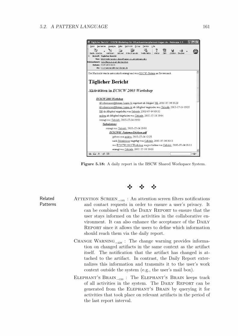
5.2. A PATTERN LANGUAGE 157
pends on the access patterns for the information. If activitiesare mainly accessed by time or user they are easier to find in arepository. If they are accessed for a specific artifact they canalso be stored directly with the artifact. For the collaborativesetting of Elephant’s brain, one should in any case ensurethat not only modifying accesses are stored (as it is the casein the original Edition pattern).
Shared Repository: The log should be modeled as a sharedrepository (Mularz, 1995) to keep it open for future additionalapplications as well as future additional awareness views.

158 CHAPTER 5. THE PATTERN LANGUAGE
5.2.8 Daily Report
Alternative name(s): Daily Summary, Change Report,Newsletter
Inform the user about changes on relevant artifacts in a user definedIntent
frequency (e.g., once a day).
Users collaborate asynchronously by modifying shared objects.Context
� � �
Changes in indirect collaboration are only visible by in-Problem
specting the changed artifact. Users want to react to otherusers’ actions but they cannot predict when these actionstake place.
German banks have to inform their customers on transactions onScenario
their bank account at least once a month. The reason for that is thatcustomers need to be able to object to transactions that they didnot approve. But since the bank can not undo transactions that aretoo long ago, they have limited the period in which a customer canobject to 30 days. Normally, customers use the account statementprinter to get the information on transactions. But if the customerdid not use the system for a long period, the bank sends an accountstatement by postal mail.
You should consider to apply the pattern when . . .Symptoms
– Users rely on each others’ activities but cannot predict whenthe activity will take place.
– Users frequently scan for changes but rarely find changes.
– Collaboration takes longer than needed since users do not scanfor changes as frequently as they appear.
– The community performs many modifications each day so thatdirect notifications for each change would consume too muchof the user’s attention or would be too expensive.

5.2. A PATTERN LANGUAGE 159
Therefore: Inform the user periodically about changes thatSolution
took place between the last notification and the time of thecurrent report.
The user defines an interest profile manually or automatically basedCollaborations
on his access rights in the collaborative system. He also definesa notification interval and a communication channel by which hewould like to be notified.
After the interest interval has passed (in most cases at night),the system checks if artifacts matching the interest profile have beenmodified within the last time interval. If this is the case, the systemputs meta-information on the change into a daily report. The dailyreport with information on all matching modified objects is sent tothe user using the provided communication channel.
Meta information can, e.g., contain a short description of the ar-tifact, information regarding the person who modified the artifact,and the time and type of the modification. It should include a quickreference to the changed artifact to ease the process of accessing it.
The check for changed artifacts can take place in two alterna-tive ways: (1) the system can query the time stamps of all objectsand search for those time stamps that fall in the notification inter-val. This has the advantage that the artifacts only have to carry atime stamp and no additional data structures are needed to trackchanges. Information regarding the performer of the change needsto be stored with the artifact if such information is desired in thedaily report. Alternative (2) is to track all changes in an Ele-
phant’s Brain→150
and query the Elephant’s Brain for activi-ties that took place in the notification interval. Since the activitiescarry all required meta information (performer, time stamp, andtype of the activity), this information does not need to be part ofthe artifact. However, the number of recorded activities may soongrow and slow the system down.
Users get informed on changes. This allows them to react to otherRationale
users’ actions. The fixed interval of change notifications ensuresthat other users can predict when the local user will read thechanges. Compared to immediate change notifications the inter-val reduces the number of interruptions. Since users are able totailor their report it will only contain relevant information. Forthat reason, the user will probably read the report.
Before applying this pattern, you should answer these questions:Check
– How frequently do changes occur and how long do users acceptto wait until first reactions?
– How can you represent artifacts in the report medium (e.g. in

160 CHAPTER 5. THE PATTERN LANGUAGE
a mail)? Can you provide URLs that let the user access thespecific artifact by just one click?
– What is the best time to send your report? Is there a periodof low system use in which the report can be sent?
– Should users have to register for the report or do you send itautomatically (consider SPAM concerns)?
– How can users turn the report off?
– How do you support your users in specifying their interests?
– Is the report personalized (because of different interest pro-files) or will all users share the same report?
The report can be considered as spam. Make sure that the usersDanger
Spots know how to tailor the report to their needs.
In most cases it is advisable to avoid empty reports. However,users could think that the report got lost if they don’t receive anyreport.
Make sure that the report is structured in a way that can beeasily grasped. Provide enough information on the artifacts to allowa user to filter irrelevant changes without looking at the specificartifact in the system.
Known
Uses
BSCW (Bentley et al., 1997a) sends reports by e-Mail after eachday on that the content of a workspace to which the user hasaccess changed or users were active in the workspace (reading).
The user can define which types of events (e.g., move events,read events, or create events) should appear in his daily reportand which events should be sent immediately (by individuale-mails).
e-Commerce Web Sites often allow users to store their interestsand their e-Mail address on the server. Whenever a new itemis added to the system or an old item is changed, the systemsends a notification mail informing the potential customer thatthere might be a an opportunity for a customer-vendor inter-action (e.g., buying a house as shown in the report extract infigure 5.19).
Mailing lists like the Yahoo Groups 1 often provide options forcontrolling the frequency of messages sent to the user. Theuser can decide if he wants to receive individual messages ordaily reports. The reports can contain all message contents orjust the headers with links to the individual messages in theweb-based mail folder.
1http://groups.yahoo.com

5.2. A PATTERN LANGUAGE 161
Figure 5.18: A daily report in the BSCW Shared Workspace System.
� � �
Related
Patterns
Attention Screen→195
: An attention screen filters notificationsand contact requests in order to ensure a user’s privacy. Itcan be combined with the Daily Report to ensure that theuser stays informed on the activities in the collaborative en-vironment. It can also enhance the acceptance of the Daily
Report since it allows the users to define which informationshould reach them via the daily report.
Change Warning→228
: The change warning provides informa-tion on changed artifacts in the same context as the artifactitself. The notification that the artifact has changed is at-tached to the artifact. In contrast, the Daily Report exter-nalizes this information and transmits it to the user’s workcontext outside the system (e.g., the user’s mail box).
Elephant’s Brain→150
: The Elephant’s Brain keeps trackof all activities in the system. The Daily Report can begenerated from the Elephant’s Brain by querying it foractivities that took place on relevant artifacts in the period ofthe last report interval.

162 CHAPTER 5. THE PATTERN LANGUAGE
Figure 5.19: A daily report at an e-commerce site showing new offers.

5.2. A PATTERN LANGUAGE 163
5.2.9 Hello Hello
Alternative name(s): Welcome Area
Photo: Photo Library of Congress, free at
www.visipix.com
You say yes, I say no. You say stop and I say go go go, oh no. Yousay goodbye and I say hello. Hello hello I don’t know why you saygoodbye, I say hello.
John Lennon, Paul McCartney
List new members of a group or a community at a prominent placeIntent
and introduce them to other members.
You have established a group and initial users have created socialContext
bonds. By this way the group has found its identity. The groupmembers distinguish themselves from people who are not part ofthe group.
� � �
If the group wants to progress it is often needed that theyProblem
integrate new members. But since the group members arevery focused on their internal interaction they may fail tonotice new potential members and ignore their possiblecontribution.
Consider a scientific conference in the area of computer science.Scenario
More than hundred researchers gather for several days to presenttheir research results and exchange ideas. Besides the exchangeof new ideas, the main objective of the conference is to maintainexisting and extend new research contacts.
But will all participants be able to exchange ideas? More ex-perienced visitors are eager to maintain existing contacts and getthe latest news from colleagues they met in the years before. Thistakes time, and time is limited. It is often only by accident thatreturning visitors get in contact with researchers who participate at

164 CHAPTER 5. THE PATTERN LANGUAGE
the conference for the first time. And – since the community doesnot know the newcomers’ faces – it is very likely that the ideasof the newcomers will only have limited space for discussion andexchange.
In contrast, one can often observe that newcomers and returningparticipants form two distinct groups – with distinct parties in theevening. This makes the exchange of ideas and learning inside thecommunity difficult.
You should consider to apply the pattern when . . .Symptoms
– long time community members have established tight links andare eager to communicate within the community.
– long time members share a large collective history, in whichnew members did not play any role.
– the community is large enough to allow the formation of sub-groups so that long time community members form a closedgroup.
– new members find it hard to enter the community.
– new members are ignored by long time members.
– fresh ideas that bring the community forward are provided bynew members but ignored by existing members.
Therefore: Provide a prominent place in the community’sSolution
interaction space where new members and their ideas areintroduced. In a computer mediated group, this can forinstance be a special section on the group’s home page.Whenever a new member joins the community ensure thatthe existing group members notice the new member.
Collaborations Welcome Area: The welcome area is a prominent region in thecommunity’s interaction space. It can be a special spatial areain a physically co-located community, a special page in a vir-tual web-based community, or a special topic or thread on adiscussion board. While the first two examples are bound to aspatial dimension, the last example is bound to a temporal di-mension. It denotes a specific time span where the communitymembers use their interaction space as a welcome area.
Newcomer: The newcomer joins the community. He introduceshimself in the welcome area and explains why he wants to bea part of the community.
Veteran: A veteran shares a long interaction history within thecommunity. He is an accepted member and keeps many sociallinks to other people. The veteran commits to visit the wel-come area frequently. In cases, where the welcome area is a

5.2. A PATTERN LANGUAGE 165
specific point in time, the veteran commits to participate inthe community at this point of time.
Since the newcomer is asked to introduce himself, he is providedRationale
with a forum where he can articulate his ideas and thoughts thatdrove him to join the community. Since all newcomers act thisway the newcomer does not have to fear that his introduction coulddisturb existing members.
Due to the commitment of the veterans, they will notice whenthe newcomer introduces himself. Thus, the newcomer will be rec-ognized by the existing community members.
The benefit of using a designated welcome area is that the in-troductions do not interfere with other group interaction. Veteranscan decide consciously when to visit the welcome area (in caseswhere it is a special place) or the whole group will focus on thewelcome area at the same time (in cases where the welcome areais a specific time frame). This ensures that there is no overlap be-tween the introduction of new members and the interaction withinthe group. Whoever is present in the welcome area concentrateson the welcoming phase. This way, veterans and newcomers con-struct a common experience that can serve as the basis for creatinga collective history.
Before applying this pattern, you should answer these questions:Check
– How can you technically detect newcomers? Is there a regis-tration procedure?
– How long should newcomers be part of the group before theyare asked to introduce themselves in the welcome area?
– Does it make sense that users decide on their own when theywill introduce themselves (if yes, how do they decide)?
– Does it make sense to introduce users who have not yet pro-vided personal information?
– Can you connect the welcome area with other interaction areasthat are of high relevance for the veterans (e.g., by interleavingthe welcome area and an alumni event)?
Newcomers may not wish to attract much interest at the first timeDanger
Spots they join the group. They may need some time to look passively atthe group and see how the group members interact. In this case,you should move the welcoming ceremony to the point of time whenthe member actively decides to participate in the group. Until then,newcomers can act with a Masquerade
→196.
Another problem can be to convince veterans to commit them-selves to pay attention to the welcome area. Veterans may just

166 CHAPTER 5. THE PATTERN LANGUAGE
not see the need for investing efforts for newcomers. This is anindication that the community is resistant to growth. Consideringparticipation in the welcome area as part of the metric that calcu-lates the users’ ranking in the Hall of Fame
→232can help to solve
this issue.
Known
Uses
ChiPlace (Girgensohn and Lee, 2002) was used at CHI2002 tofoster networking between attendants of the conference beforethe conference took place. Users could provide a descriptionof themselves. When entering the people page (cf. figure 5.20,left), a list with new members was shown in a prominent sec-tion (at the beginning of the page). Clicking on the user’sname opened a user profile (cf. figure 5.20 right).
Figure 5.20: New members at CHIplace.
www.visualbuilder.com is a community of software developers.New members are listed in a designated welcome area on theentry page (shown in the left part of figure 5.21). Clickingon the user’s login opens another page that shows the user’sprofile (right part of figure 5.21).
www.communities.com (cf. also the known uses section ofUser Gallery
→197) allows to query new members can be

5.2. A PATTERN LANGUAGE 167
Figure 5.21: New users at www.visualbuilder.com and a user profile.
queried by clicking on the “New Members” link (in the rightpart of figure 5.22). This will show the list of users that isshown in figure 5.22. By clicking on the user’s login, one cansee the provided information.
Games at EuroPLoP are special slots in the conference schedulewhere the participants meet for cooperative games. The gameshave the purpose of getting in touch with each other. Namegames help to learn the participants’ names and other gameshelp to find similarities between the participants.
� � �
Related
PatternsMentor
→236: Newcomers, who introduced themselves in the wel-
come area, can be paired with a mentor who accompanies thenewcomer in his first steps and personally introduces him torelevant veterans.
Masquerade→196
: To allow newcomers to interact within the com-munity without exposing themselves, they can move throughthe community anonymously. The Masquerade pattern dis-cusses this form of interaction in depth.
Hall of Fame→232
: The Hello Hello pattern focuses on theintroduction of newcomers to veterans. The opposite is donein the Hall of Fame: here, honorable community membersare presented to the community to provide newcomers with anorientation, who influenced the community most.

168 CHAPTER 5. THE PATTERN LANGUAGE
Figure 5.22: A welcome area at www.communities.com.
Big Jolt (Manns and Rising, 2004) proposes to invite a knowl-edgable expert to the community who will tell about his ex-perience in the field. Inviting the expert to the welcome areacan serve two means: First, the welcome area receives a higherreputation since it is not only a place to meet newcomers butalso to get in touch with experts. Second, newcomers will learnmore about the ideas that the community propagates. If theexpert is a community member himself, he will probably beone of the top members in the Hall of Fame
→232.
User Gallery→197
: The welcome area is often a special section ofthe User Gallery.
Introduction Session (Fricke and Volter, 2000) proposes a wel-coming phase at the beginning of a seminar. It shows how theproblem of learning more about newcomers (in this case allseminar participants are considered as newcomers) can be re-solved in a co-located seminar. The solution is to “take timeat the beginning of the seminar to let everyone introduce him-/herself to the others.”

5.3. SUMMARY 169
5.3 Summary
In this chapter we discussed parts of a pattern language for supporting group forma-tion by means of enhanced awareness mechanisms.2 The following factors influencethe context for group formation: the focus of the users’ current activities (artifacts),the type of interaction (ranging from single-user hci to tightly coupled group in-teraction), and the distance in time ranging from past activities over synchronousinteraction up to planned activities.
The presented patterns ease the transition in the direction of tightly coupledsynchronous interaction with a shared focus. They rely on observing the users’activities and providing activity awareness on related activities.
The patterns are examples for patterns at different abstraction levels. Technicalpatterns like the Gaze Over the Shoulder
→145or the Elephant’s Brain
→150
address issues of data management and interaction tracking. At the other end ofthe spectrum social patterns like the Hello Hello
→163pattern describe a process
of group interaction. It can be supported by technology but does not need thetechnology to work.
The next chapter will report on the experiences made with groupware patternsin the context of the Oregon Software Development process.
2Note again that additional thumbnails can be found in the appendix.

170 CHAPTER 5. THE PATTERN LANGUAGE

Chapter 6
Experiences
The goals of the validation are twofold: First, we have to see to what extent a teamof developers and users is able to follow the OSDP and create software that matchesthe users’ needs. Second, we have to discuss the validity of the groupware patternssince they are the most important tool in the OSDP.
After these two fundamental issues have been studied, we need further evidencewhether or not the OSDP really satisfies the requirements outlined in section 2.Finally, we need to check if groupware created with a process that satisfies therequirements really is accepted by the users and eases their interaction.
6.1 Observation Method
Validation of software processes in general is problematic since one cannot performa development task twice with the same preconditions. And even if this would bepossible, the preconditions would be hard to define. Traditional controlled lab ex-periments, as one could use, e.g., for studying the usability of a software system aretherefore very inappropriate for the evaluation of software development processes.They would place the observed participants in an artificial environment, which as-sumes that one can define all external forces of the development process. But since,by definition, groupware development is a wicked problem, it is especially not pos-sible to define all external forces of groupware development beforehand. Anotherargument against lab studies is that realistic software development projects are oftenlong-term projects lasting more than one year. Controlling the lab setting for sucha long time frame is in most cases not possible.
A different evaluation method is thus needed to better understand the effects ofthe OSDP and the value of the pattern language. McGrath (1984) has classifiedstrategies for group studies along different dimensions (fig. 6.1):
– The unsophistication of the setting (inner circle of fig. 6.1). Observations canbe
. embedded in natural systems,
171

172 CHAPTER 6. EXPERIENCES
Obtrusive
research
opertaions
Unobtrusive
research
opertaions
Universal
behavior
systems
Particular
behavior
systems
Laboratory
experiments
Experimental
simulations
Judgement
studies
Field
experiments
Sample
surveyField
studies
Computer
simulations
Formal
theory
maximum
precision
maximum
generality over
actors
maximum
realism in
context
Settings in
natural
systems
Contrived
and created
settings
No
observation
of behavior
required
Behavior
not setting
dependent
Goal1
Goal3
Goal2
Figure 6.1: Research strategies for group studies (McGrath, 1984) and their applicability for
assessing the OSDP (darker areas better fit the needs of the OSDP evaluation).
. performed in contrived and created settings,
. independent of a concrete setting, or
. unimportant since the evaluation takes place on a theoretic level.
– The observed behavior can be universal and thus applicable to many contextsor it can be particular, which makes it hard to generalize (horizontal axis offig. 6.1).
– The method can be obtrusive or unobtrusive (vertical axis of fig. 6.1). If theresearch method is obtrusive, the subject will be aware of the fact that it takespart in a research study. This, however, can affect the subject’s behavior.
McGrath pointed out that none of the research strategies leads to a perfect resultthat would support three goals shown in fig. 6.1:
1. generalizable over populations of actors,
2. precise in the sense that exactly the variables in which the researcher is inter-ested are studied, and
3. realistic with respect to the context.

6.1. OBSERVATION METHOD 173
As shown in fig. 6.1, the optimal configurations for each of the three goals forms atriangle. Perfecting one goal thus weakens the other goals. For that reason, McGrathproposed that an evaluation should combine different strategies in order to paint avalid picture of the evaluated process.
In the context of the OSDP evaluation, this means that we have to select differentevaluation strategies. The results will provide partial but complementary evidence.
To reach maximum precision, a comparative laboratory experiment would be thepreferred evaluation method. However, such a study would require that we knowexactly what the previous knowledge of each team member is. We would furtherneed to compose two teams with exactly the same previous knowledge and ensurethat one team follows a traditional approach and another team follows the newapproach.
Both teams would also need the same explicit and implicit goals. To be able tocompare the teams, we would need two teams with the same attitudes and wishesregarding a design problem.
These factors make comparative studies rather difficult and, above all, artifi-cial. The realism and context would be insufficient. So, we decided not to includecontrived and created settings in the evaluation.
The maximum realism in context can be reached with field studies. Using thismethod means that the observer lives with the team for a longer period of time. Thegroup process is not manipulated by the observer. Occasionally, the observer canask questions to better understand the observed behavior. For the OSDP, this wouldmean that the behavior of a group is observed that applies the OSDP. The projectcontext and the project goals need to be natural settings and the manipulation ofthe groups should be limited.
The main advantage of this approach is that also external factors that were notconsidered in an experimental layout can be observed during the study. We thereforedecided to apply the OSDP in the field and to perform a field study in which we usedthe OSDP for the development in a large software project (i.e., the CURE project).We will present our observations in sections 6.2–6.5.
A problem with the CURE study was the expertise of the members of the devel-opment team. All of them were experienced software developers. Thus, the learningaspect (R10 and R11) for members of the development team could not be validatedin the CURE project. We thus complemented the results of the CURE study with afield experiment. Again, the evaluation took place in a naturalistic setting, a devel-opment project. The difference to the CURE project was that the project goal wasmore clearly defined, that the project duration was shorter, and that the developerswere less experienced. We observed the cases of three student theses. In each case,a single student was asked to create a collaborative application using the patternsas educative means. The observer played the role of the customer who defined theoverall goals of the application. The student had to perform all design activities(the customer did not participate in the design). The selection of patterns and thetransformation of patterns to the concrete application context was monitored by theobserver. The observations will be presented in section 6.6.
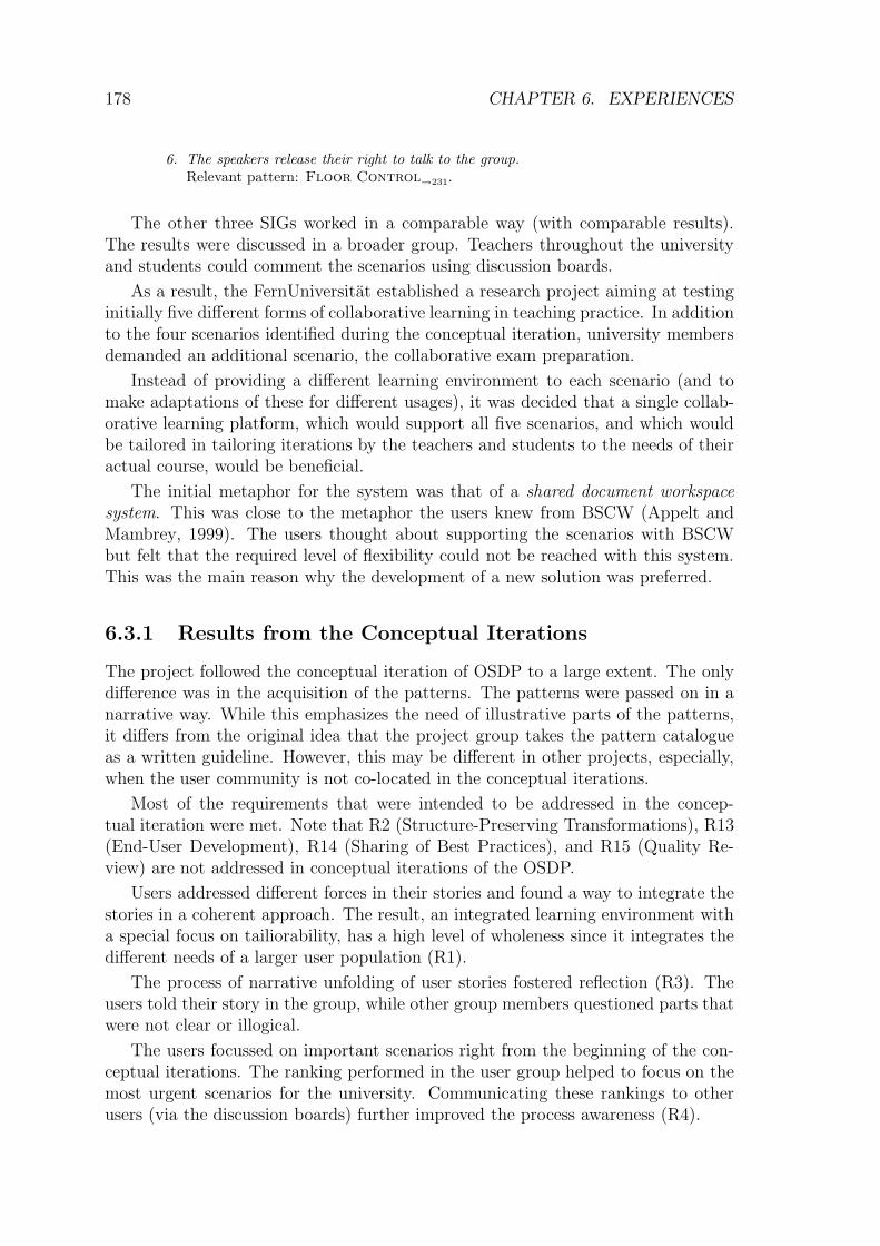
174 CHAPTER 6. EXPERIENCES
The field study of the CURE project together with the field experiments ofthe student projects cover the evaluation made in a natural setting. To achievegenerality, these settings are combined with findings from theoretical considerationsand expert assessments (falling in the category of expert studies).
The theoretical considerations are based on Alexander’s theory of wholeness.The question is whether or not a sequence as it occurs in the field study leads towholeness. Alexander proposed 15 fundamental properties that describe systemswith a high level of wholeness. A specific sequence is described in section 6.4.3 witha special focus on the wholeness created by the sequence.
The expert assessment focuses on how the written descriptions of the OSDP andthe patterns have been reviewed by peer experts. A short summary of this aspectwill be given in section 6.7.1
A summary of the findings of these four ways of gathering experiences will con-clude this chapter.
6.2 Context of the CURE Project
The CURE project was a two year project with the goal of creating a collaborativelearning environment for the FernUniversitat in Hagen (Haake et al., 2004a).
The FernUniversitat in Hagen is the German distance learning university. Teach-ing at the FernUniversitat includes different forms of learning: courses, seminars,and different forms of practical problem solving in lab courses. Course materialand accompanying individual exercises are sent to distributed students via surfacemail or the Internet. Course-specific newsgroups and direct e-mail communicationwith professors and teaching assistants support asynchronous discussions. Studentsmight also use the telephone to contact staff directly. In addition, students can meettutors and other students at one of the 60 learning centers, if one exist near theirlocation.
Since 1996, the FernUniversitat is active in developing new technical infrastruc-tures for supporting distance education. The Platform 2000 was an integrationproject with the goal of combining different systems that were in use for the sup-port of learning management at the FernUniversitat (Feldmann-Pempe et al., 1999;Kramer, 2000; Feldmann and Schlageter, 2001).
The emergence and ubiquity of computer mediated communication and interac-tion has, however, changed the expectations of the students at the FernUniversitat.Regarding interactivity, these expectations exceed traditional course or content man-agement that was offered by the Platform 2000. Although the traditional ways ofdistributing printed material to the students are still very important for the stu-dents, they demand tighter interaction with and better support from teaching staff.Especially since the studies are no longer free of charge, the students concentrate
1Borchers (2001) used a comparable combination of expert assessment and the applicationof patterns in student projects in order to validate his pattern collection for human-computer-interaction design.

6.3. CONCEPTUAL ITERATIONS IN CURE 175
on receiving qualified help and finishing their studies as soon as possible. Teachingstaff on the other hand has the goal of establishing learning communities that fostermutual help between students, improve the learning results, and relieve teachingstaff in times of short financial budgets.
In 2002, the FernUniversitat initiated a project group with the goal of examiningopportunities for collaborative learning.
6.3 Conceptual Iterations in CURE
From summer 2002 on, a group of teachers from different faculties, members of theuniversity’s data processing service center, student representatives, and researchersfrom the chair for distributed systems gathered and exchanged different scenariosfor collaborative learning. In an initial session, all group members reported on theirexperience with collaborative episodes in higher education. The group collectedten different scenarios. All scenarios were discussed with a broad user audience inthe university’s discussion board. Based on the students’ feedback, four of thesescenarios were rated as most important. They were collaborative exercises, tutor-guided groups with collaborative exercises, virtual seminars, and virtual labs.
A scenario interest group was formed for each scenario with the goal of refiningthe scenarios and creating first sketches for computer support in order to provide acommon ground for discussing a potential development of a collaborative learningenvironment. The scenario interest groups had four to seven members.
We concentrate on the SIG that considered the area of virtual seminars. It hadin total five members from the department of psychology (with the goal of support-ing virtual seminars), the distributed systems department (a member of the futuredevelopment team who had the goal of transferring the scenario into developmentiterations), and students who contributed their experiences with seminars.
As a first step, the group members met in a co-located session and discussedforces of seminars (the goals of the participants) and created a scenario of traditionalseminars with talks, each presented by two students. The following text is a fragmentof the first story. It considers the phase of a traditional seminar in which all seminarparticipants participate at the same time (presentation phase).
The students Marks and Alice prepared a seminar lecture on the topic of cooperativesoftware development. 15 minutes before the scheduled start of the seminar, theyenter the seminar room. They connect their portable computer to the provided LCDprojector and check if the slides are readable. More or less on time, the other seminarparticipants enter the seminar room. Speakers and the audience notice one anotherand greet each others. The speakers are glad to see that two external visitors came tojoin their talk. This encourages them to give an even better presentation. The visitorswere pleased that they were given the opportunity to join the talk of which they heardin the local newspaper.
Due to a traffic jam, the teachers arrived 15 minutes late. The speakers waited forthem and all participants chatted on arbitrary themes. The seminar leader providesan introduction and welcomes the speakers. Then he hands over to the speakers.The speakers present their prepared talk. They make use of modern media like video

176 CHAPTER 6. EXPERIENCES
and audio clips to make their presentation a bit more thrilling. Karl, a member aufthe audience, raises his hand since he would like to ask an intermediate question.However, Marc and Alice ask him to wait until they finished their prepared talk. Karlis annoyed but waits.
After the presentation, Mark and Alice ask for questions. Karl, the teacher, and threeother students have an interesting discussion. The other students do not take part inthe discussion. Mark and Alice think that the lecture was a success and are motivatedto prepare an essay that summarizes their talk.2
The development team member then introduced the other SIG participants topatterns for groupware development. The introduction was kept on a very informallevel. The main focus was on the known uses and the scenarios of the patterns. Thedevelopment team member took the role of moderating the process according to theneeded steps of a conceptual iteration.
Together, the SIG members discussed the phases of the story, converted it tomore formal scenarios that take the transition to a virtual context into account.Each step of the scenarios was attributed with patterns that could support the step.The SIG members also discussed opportunities for a different dramaturgy of thescenarios. The story resulted in five scenarios on different levels of abstraction. Thefirst three scenarios are shown below:3
Scenario: Run a Virtual Seminar
Main actor: StudentsStakeholders: Teachers, Students
1. Students register to the seminar.
2. Students introduce themselves to the other participants of the seminar.Relevant patterns: Virtual Me
→197, Hello Hello→163.
3. Students select a desired topic and create groups. The seminar support sys-tem offers recommendations for potential co-learners. The system provides thegroup with a shared workspace to store their documents.Relevant patterns: Birds of a Feather
→199, Opposites Attract→236,
Shared Folder→182.
4. The group defines and publishes their goals and mile stones for participating inthe seminar.Relevant patterns: Centralized Objects
→228, Shared Folder→182.
5. The group prepares their seminar talk and discusses overlapping aspects withother seminar groups. The teachers control the compliance with the mile stones.Relevant Pattern: From Shared Data to Shared Work
→120.
6. Groups give their talk in a synchronous presentation phase (cf. detailed usecase).
7. The groups submit their final essays to the teachers. The teachers read andcomment the essays and finally provide a clearance for publication.Relevant patterns: Shared Annotation
→241, Authoritative
instance→226, Letter of Recommendation
→233.
2Note that the scenarios and all other examples were translated from German to English.3A previous German version (without pattern attachments) can be found at http:
//www.fernuni-hagen.de/LVU/intern/gremien_niederschriften/CSCL_Anwendungsfall_
virt_Seminar.pdf.

6.3. CONCEPTUAL ITERATIONS IN CURE 177
8. The groups publish their essays and inform other group members about thesubmission.Relevant patterns: Shared Folder
→182, Change Warning→228.
9. During the wrap-up phase, the students discuss and annotate the essays.Relevant patterns: Shared Annotation
→241, Threaded Discussions→242.
10. The teachers ask the students for feedback regarding the seminar.Relevant pattern: Letter of Recommendation
→233.
Scenario: Synchronous Presentation Phase in a Virtual Seminar
Main actor: SpeakersStakeholders: Students (including Speakers), Guests, Teachers
1. Users (speakers, students, guests, and teachers) log on to the presentation sys-tem. The presentation system provides information about other connected usersand their roles.Relevant patterns: Login
→181, User List→141, Role
→240, Virtual Me→197.
2. The speakers transfer their prepared material to a workspace of the presentationsystem.Relevant patterns: Shared Folder
→182.
3. The teacher grabs the right to speak (his role allows him to do so) in the inte-grated communication channel (chat).Relevant pattern: Floor Control
→231.
4. The teacher transmits his greetings using the chat.
5. The teacher transfers the right to speak to the speakers.Relevant pattern: Floor Control
→231.
6. The speakers present their talk (cf. the additional scenario below).
7. The speakers release the right to talk (resp. type in the chat) and open thediscussion.Relevant pattern: Floor Control
→231.
8. Students ask questions. The speakers or other students provide answers to thequestions.Relevant pattern: Moderator
→236.
9. The users disconnect from the presentation system.Relevant patterns: Login
→181 (Logout), Lights off→234.
Scenario: Speakers Present Their Talk
Main actor: SpeakersStakeholders: Listeners, Speakers
1. The speaker receives the right to speak.Relevant pattern: Floor Control
→231.
2. The speaker moves to an illustrative page from his prepared material. Thepresentation system ensures that this page is shown on all listeners’ screens.Relevant pattern: Travel Together
→243.
3. The speaker provides a comment on the shown material using the chat channel.
4. If desired, the speaker transfers his right to speak and present to his co-speaker.Relevant pattern: Floor Control
→231.
5. Until the end of the talk, the speakers repeat steps 2 to 4.

178 CHAPTER 6. EXPERIENCES
6. The speakers release their right to talk to the group.Relevant pattern: Floor Control
→231.
The other three SIGs worked in a comparable way (with comparable results).The results were discussed in a broader group. Teachers throughout the universityand students could comment the scenarios using discussion boards.
As a result, the FernUniversitat established a research project aiming at testinginitially five different forms of collaborative learning in teaching practice. In additionto the four scenarios identified during the conceptual iteration, university membersdemanded an additional scenario, the collaborative exam preparation.
Instead of providing a different learning environment to each scenario (and tomake adaptations of these for different usages), it was decided that a single collab-orative learning platform, which would support all five scenarios, and which wouldbe tailored in tailoring iterations by the teachers and students to the needs of theiractual course, would be beneficial.
The initial metaphor for the system was that of a shared document workspacesystem. This was close to the metaphor the users knew from BSCW (Appelt andMambrey, 1999). The users thought about supporting the scenarios with BSCWbut felt that the required level of flexibility could not be reached with this system.This was the main reason why the development of a new solution was preferred.
6.3.1 Results from the Conceptual Iterations
The project followed the conceptual iteration of OSDP to a large extent. The onlydifference was in the acquisition of the patterns. The patterns were passed on in anarrative way. While this emphasizes the need of illustrative parts of the patterns,it differs from the original idea that the project group takes the pattern catalogueas a written guideline. However, this may be different in other projects, especially,when the user community is not co-located in the conceptual iterations.
Most of the requirements that were intended to be addressed in the concep-tual iteration were met. Note that R2 (Structure-Preserving Transformations), R13(End-User Development), R14 (Sharing of Best Practices), and R15 (Quality Re-view) are not addressed in conceptual iterations of the OSDP.
Users addressed different forces in their stories and found a way to integrate thestories in a coherent approach. The result, an integrated learning environment witha special focus on tailiorability, has a high level of wholeness since it integrates thedifferent needs of a larger user population (R1).
The process of narrative unfolding of user stories fostered reflection (R3). Theusers told their story in the group, while other group members questioned parts thatwere not clear or illogical.
The users focussed on important scenarios right from the beginning of the con-ceptual iterations. The ranking performed in the user group helped to focus on themost urgent scenarios for the university. Communicating these rankings to otherusers (via the discussion boards) further improved the process awareness (R4).

6.4. DEVELOPMENT ITERATIONS IN CURE 179
During the early phases of the project, users performed several conceptual iter-ations (R5). The products of the SIGs (scenarios and mock-ups) were refined anddiscussed in the larger user group. The discussions helped to gradually meet theusers’ needs.
Each SIG focussed on one scenario at a time. Scenarios however comprisedseveral problems. Thus, the focus was not yet on one problem at a time. Theonly point in time, where the SIG members reached this intensive focus was whileattributing the different steps of each scenario with pattern candidates. In thisphase, the SIG members successfully focussed on one problem at a time (R6).
The understanding of forces (R7) was not as exhaustive as intended. Users triedto describe the field of forces of their situations. But since the narrative was notdirectly situated in the task of the seminar, the forces were not as easy accessibleas if it would be the case for an analysis that takes place during the seminar. Con-sequently, the requirement for making forces explicit R8 and the requirement forbetter understanding the consequences R11 was not met sufficiently.
The conceptual iterations involved a large user community. Especially the pro-cess of discussing the scenarios in public discussion boards led to good end-userparticipation (R9).
Education of end-users (R10) took place by passing on the ideas of the groupwarepatterns. The integration of the solution with the user’s daily context (R12) wasensured by basing development activities on stories brought in by the users fromtheir daily teaching background.
6.4 Development Iterations in CURE
The development team consisted of four senior employees and three students whocontributed to the development. Except the technical project leader, none of thedevelopers has been involved in the development of community systems before.
The end-users were university teachers, who wanted to use one or more of theabove learning scenarios in their teaching, and students with the goal of improvingtheir learning conditions. They had already participated in the first conceptual it-erations and stayed in the SIG when their topic entered a development iteration.Some of the SIG members have tried different collaboration technology before (es-pecially BSCW and Newsgroups). Others had only limited experience with usingthe internet for distributed teaching.
The SIGs met for an initial planning game to further investigate the forces of thescenarios discovered in the conceptual iteration. The result of these SIG meetingswere three sorted SIG backlogs. They contained task cards related to the steps inthe scenario. Each task card was rated by the development team regarding its effortsand by the users regarding the importance. In early iterations, the content of thetask cards was still quite vague. A first set of top-rated task cards e.g. included thetask of creating a shared workspace at the system’s server. The shared workspacemetaphor, which was chosen by all SIGs in the first iteration, thus became the

180 CHAPTER 6. EXPERIENCES
system metaphor and was implemented with highest priority.
Figure 6.2: The project backlog of early phases.
The technical project leader took the role of the gardener in the early phasesof development. He merged the task cards from the different SIGs and created aproject backlog for the first iterations (containing approx. 30 cards). The cardswere put on a whiteboard that was accessible by all development team members (cf.fig. 6.2). Other SIG members had difficulties accessing the cards since they workedat other locations.
This problem was solved as soon as the CURE environment supported the cre-ation and manipulation of pages. From then on, the planning cards were managedwithin CURE in a development room and users could access and modify cards. Inearly phases, users made not much use of this option, but later on, they startedto contribute to the planning cards in CURE. Especially, many users followed theactivities that were published in the development room.
Figure 6.3 shows an example of the backlog used in March 2004. Each entry in theleft list maps to a planning card (shown in the right window). In this example, theteam member Britta Landgraf has implemented a card that addresses the possibilityof public keys for rooms. After completing her task, she reflected on her activitiesand wrote relevant insights to the lower part of the card. She also tracked the realeffort in order to improve the estimation of task cards.
6.4.1 A sequence shaping the collaboration environment
The first card was the Login card. In compliance with the Login pattern, it statedthe goal that users who had an account should provide information regarding their

6.4. DEVELOPMENT ITERATIONS IN CURE 181
Figure 6.3: The virtual project backlog in later phases.
identity before being allowed to access the resources on the server.
Login
Problem: You are developing an application that requires non-anonymous interac-tion.
Solution: Provide a Login screen that requests users to identify themselves byentering a login name and a password before they can start to use the application.
Known Uses: www.ebay.com, www.amazon.com
The team implemented a servlet that generated the required login form andprocessed the provided login and password. Note that the SIG rated this task asmore important than, e.g., the first step in the first scenario shown above (Studentsregister to the seminar). The different importance received during the planninggame revealed that some parts of the scenarios are nice to have, but not crucial forfulfilling the task of a virtual seminar.
In order to be able to present the solution, the next task card had to be imple-mented as well, which was the document workspace card. It was influenced by theShared Folder pattern:
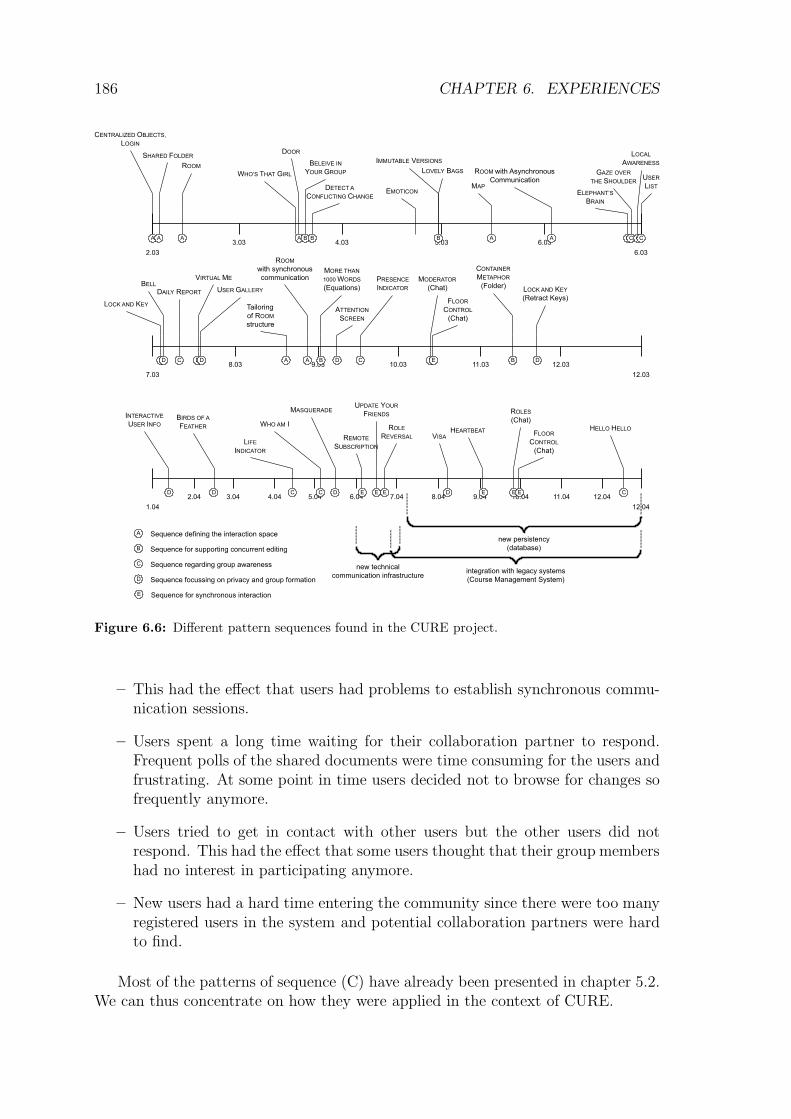
182 CHAPTER 6. EXPERIENCES
Shared Folder
Problem: Different collaborating groups share a lot of data. Due to the amount ofdata from different groups, users cannot find the data they need for collaboration.
Solution: Allow groups to organize their shared data in composites that are modeledas Centralized Objects.
Known Uses: BSCW (Appelt and Mambrey, 1999), FTP-Server, WebDAV
The resulting system could be used already. Users could log in to a system andbrowse material stored in a shared folder. First experimental use revealed that theusers missed the opportunity to also communicate about the content. This made theSIG members reconsider their system metaphor of a shared document workspace.They examined the pattern space again and found the Room pattern:
Room
Problem: When distributed users want to collaborate, they have to deal with manytechnical issues to initiate the collaboration. They have to set up communicationchannels and make the shared material available to all group members. Results of theshared collaboration often need to be captured for later reference. All these tasks areerror-prone and require technical expertise, which users often don’t have.
Solution: Model a virtual place for collaboration as a room, which can hold doc-uments and participants. Ensure that users, who are in the same room at the sametime, can communicate by means of a communication channel that is automaticallyestablished between all users in the room. Make sure that all users can perceive alldocuments that are in the room and make these documents persistent. That includesthat changes on these documents are visible to all members in the room.
Known Uses: VITAL (Pfister et al., 1998), Lecture2000 (Schlichter et al., 1998),LambdaMOO (Curtis, 1998), CollegeTown (Guernsey, 1996), TeamWave (Greenbergand Roseman, 2003), DIVA (Sohlenkamp and Chwelos, 1994)
The pattern conceptually helped the users to understand the difference betweenstructuring the virtual learning environment and interacting within the environment.Users who are in the same room can access all pages that are contained in the room.Changes of these pages are visible to all members in the room.
The room metaphor served as the most important metaphor during the followingdevelopment. The pattern was not implemented with all aspects in the first iteration.First aspects included a set of pages and tools to manipulate the pages.
Note that the conceptual understanding was sufficient for the users at this timein the project. They now knew where their communication mechanisms would beanchored and how communication channels would be managed in the system. Theimplementation of communication features was postponed to later phases in theproject. Four months after the development of the first room, a mailbox was addedto allow asynchronous communication. Another three months later, the rooms wereequipped with a persistent chat that was always visible to users present in the room.

6.4. DEVELOPMENT ITERATIONS IN CURE 183
Figure 6.4: A room in CURE.
Figure 6.4 shows a typical room in CURE after the communication features wereadded.4 It contains documents (in the example, two users discuss the concept ofentropy for which a document has been created in the room Verteilte Systeme). Itprovides two room-based communication channels: a mail box and a chat.
The Room pattern opened up a design space that was not considered before. Asdiscussed in the Room pattern, rooms could be connected to form a virtual learningenvironment. A task card to implement the Door pattern was therefore added tothe project’s backlog (and placed on a high-priority position since the users wantedto be able to connect several rooms).
Door
Problem: In virtual rooms, objects and characters can only interact with peers inthe same room what limits their possibilities. Especially, interaction between differentgroups cannot easily be supported.
Solution: Use doors between rooms as a means for navigating between rooms. Modeldifferent states of the door to reflect the mutual accessibility of the related rooms.
4Note that the screen shots were taken at different points in time of the project life (to reflectthe state after each pattern was applied). This, however, implies that some user interface elementsevolved over time and will not be consistent throughout all screen shots of the CURE project.

184 CHAPTER 6. EXPERIENCES
Known Uses: VITAL (Pfister et al., 1998), Lecture2000 (Schlichter et al., 1998)
Users could now move between rooms. After connecting to the system, the usersstarted in the entry hall. From that room, there were doors to other rooms wherethe learning took place (e.g. a room for the distributed systems chair or a room forlinear algebra).
By providing a plenary room, sharing and communication in a whole class or or-ganization can be supported. By creating new rooms for sub groups and connectingthose to the classes’ or organization’s room, work and collaboration can be flexiblystructured.
After the number of rooms increased (after approx. 3 months of system usage),the test users detected that they had problems to find their way through the rooms.They had problems to remember how the rooms were positioned and connected.
Thus, a graphical room-map was added to ease the orientation in the systemfollowing the Map pattern.
Map
Problem: To orient in space, users have to create a mental model that representsthe space and the contained artifacts. This is a very difficult task.
Solution: Create a visual representation of the spatial domain model by means ofa map.
Known Uses: GIA (Group InterAction) (Manhart, 1999), CVW(http://cvw.sourceforge.net/), CollegeTown (Guernsey, 1996)
The map was generated from the underlying room structure. One problem withgenerated maps was – as mentioned in the pattern – the stability of relative positions.Two simplifications of the room structure were needed to provide this stability:
– Rooms were limited to have only one entry point directed to the hall. Thismeans that the rooms could be visualized with a tree topology. Without thislimitation, the resulting map could possibly be no longer planar and thusnot drawable as a two-dimensional map with non-crossing links. Other linksbetween rooms were nevertheless possible by placing a hyperlink on any of thesource room’s pages. But these connections were not understood by the usersas doors but rather as traditional hyperlinks without any spatial meaning.
– Rooms were automatically ordered (alphabetically) and aligned in a clockwiselayout. This means that rooms still could change their positions but thatrelative order was maintained.
Figure 6.5 shows an example room structure for a distributed software develop-ment lab. An entry room is used to support interaction within the whole course(called Learning Gadgets in fig. 6.5). Each project group additionally has a grouproom in which the specific group project is run. In the example, these rooms arecalled efa, FOW, and GoGoGadgeto, which are the names of the project groups. A

6.4. DEVELOPMENT ITERATIONS IN CURE 185
discussion room serves as a discussion space for aspects that are of interest for morethan one group. To aid navigation between rooms, CURE offers a room directoryand a room map. While the room directory shows the rooms accessible to the user,and their nesting, the room map shows a graphical layout of the room structure.
Figure 6.5: Room directory and room Map in CURE.
The short sequence reported so far – Login, Shared Folder, Room, Door,Map – shows how the initial scenario gradually evolved from a document centeredapproach to a user centered approach in which users interact in collaboration spaces.The users learned – informed by the use of patterns – how to design collaborativeenvironments and how to move away from traditionally experienced interaction insingle user systems (the folder metaphor known from single-user operating systems).
Figure 6.6 shows how the different patterns influenced the development of thesystem. The patterns are arranged as events on horizontal timescales. The letters atthe bottom of each event denote the thematic sequence in which the pattern can beseen. We identified five major sequences. The first sequence focussed on defining thespace for interaction and was already described above. The second sequence (B) ad-dressed the interaction with the content of the interaction spaces. It co-evolved withthe evolution of the first sequence (A). The third sequence (C) focussed on providinginformation on the other user’s activities (workspace- and group awareness) and thefourth sequence (D) addressed issues on privacy (of work groups) and group forma-tion (getting to know each others and establishing a group environment). Finally,the last sequence (E) focussed on aspects needed for synchronous interaction.
In the following, we focus on the sequences (C) and (D) that are addressingrather socio-technical issues (compared to more technical issues in the sequences(B) and (E)). We expect to see clear evidence od OSDP’s value in these sequences.
6.4.2 A sequence addressing group awareness
Group awareness was rated as an important issue after the users made their firstexperiences of editing in the system. Forces that were rated as problematic were:
– Users felt as if they were using the system alone.

186 CHAPTER 6. EXPERIENCES
3.03
2.03 6.03
4.03 5.03 6.03
CENTRALIZED OBJECTS,
LOGIN
SHARED FOLDER
ROOM
WHO’S THAT GIRL
DOOR
EMOTICON
IMMUTABLE VERSIONS
MAP
ROOM with Asynchronous
Communication USER
LIST
8.03
7.03 12.03
9.03 10.03 11.03 12.03
2.04
1.04 12.04
3.04 4.04 5.04 6.04 7.04 8.04 9.04 10.04 11.04 12.04
LOCK AND KEY
BELL
DAILY REPORT
VIRTUAL ME
USER GALLERY
Tailoring
of ROOM
structure
ROOM
with synchronous
communicationMORE THAN
1000 WORDS
(Equations)
ATTENTION
SCREEN
PRESENCE
INDICATOR
CONTAINER
METAPHOR
(Folder)
INTERACTIVE
USER INFOBIRDS OF A
FEATHER
GAZE OVER
THE SHOULDER
ELEPHANT’S
BRAIN
LIFE
INDICATOR
REMOTE
SUBSCRIPTION
UPDATE YOUR
FRIENDS
ROLE
REVERSAL
new technical
communication infrastructure
new persistency
(database)
integration with legacy systems
(Course Management System)
HEARTBEAT
LOVELY BAGS
DETECT A
CONFLICTING CHANGE
HELLO HELLO
VISA
WHO AM I
MASQUERADE
BELEIVE IN
YOUR GROUP
LOCK AND KEY
(Retract Keys)
A A A A A A
AA
A Sequence defining the interaction space
DD D
DD
Sequence for supporting concurrent editingB
Sequence regarding group awarenessC
Sequence focussing on privacy and group formationD
Sequence for synchronous interactionE
CB B B
B
C C
C CB
CC E E E E
D
D
DD
D C
MODERATOR
(Chat)
FLOOR
CONTROL
(Chat)
EE
ROLES
(Chat)
E E
FLOOR
CONTROL
(Chat)
LOCAL
AWARENESS
C
Figure 6.6: Different pattern sequences found in the CURE project.
– This had the effect that users had problems to establish synchronous commu-nication sessions.
– Users spent a long time waiting for their collaboration partner to respond.Frequent polls of the shared documents were time consuming for the users andfrustrating. At some point in time users decided not to browse for changes sofrequently anymore.
– Users tried to get in contact with other users but the other users did notrespond. This had the effect that some users thought that their group membershad no interest in participating anymore.
– New users had a hard time entering the community since there were too manyregistered users in the system and potential collaboration partners were hardto find.
Most of the patterns of sequence (C) have already been presented in chapter 5.2.We can thus concentrate on how they were applied in the context of CURE.

6.4. DEVELOPMENT ITERATIONS IN CURE 187
The Elephant’s Brain→150
pattern was different to the patterns mentioned sofar since it was demanded by the developers, not by the end-users. Nevertheless,the forces that led the developers to the Elephant’s Brain were brought up by theusers.
Users regarded it as important to know who else is currently connected to thesystem. They hoped to create a feeling of co-presence that could lead From Shared
Data to Shared Work→120
. An appropriate means for supporting this sense ofco-presence was to provide Local Awareness
→127. But in order to calculate and
visualize confocal users, the system needed to track the users’ activities (Gaze
Over the Shoulder→145
) and store tracked activities for future analysis in anElephant’s Brain
→150.
Figure 6.7: A User List in CURE.
Users considered it important to see those users, who are currently in the sameroom. Whether or not the users were also on the same page was not so importantfor the participating users. Thus, although the Elephant’s Brain
→150proposed
to record activities on the level of artifacts (pages), the definition of confocal userswas done on the level of the room in which the artifacts reside.
The confocal users calculated by the Local Awareness→127
pattern were shownin a User List
→141. In a first iteration, this list was a textual list of user names.
In later iterations, the user names were replaced by the user’s picture (cf. Virtual
Me→197
). The most recent visual layout of the user list in CURE is shown in figure6.7.
The above example shows how the pattern language supports the decompositionand the composition of design problems (cf. fig. 6.8). Patterns on a high abstractionscale help the user to understand the overall problem and envision scenarios ofsystem use. Supportive patterns on lower levels of abstraction provide alternativesand guidance for understanding the detailed interaction in the problem context. Theuser moves down to a level of abstraction that can be used as development task bythe developer. The developer will move further down and employ technical patterns(e.g.,patterns for structuring databases or patterns like the Composite pattern ofthe GoF language (Gamma et al., 1995)). For the user, the low-level patterns define
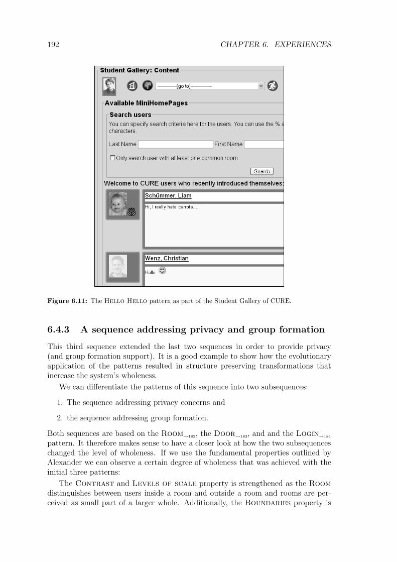
188 CHAPTER 6. EXPERIENCES
LOCAL
AWARENESS
GAZE OVER
THE SHOULDER
ELEPHANT’S
BRAIN
FROM SHARED DATA
TO SHARED WORK
GAZE OVER
THE SHOULDER
LOCAL
AWARENESS
USER
LIST
ab
stra
ctio
n
low
high
D: How to bring
users together?
D: How to detect
users’ activities?
D: How to keep
track of the users’
activities?
C: Fill the
Elephant’s Brain.
C: Calculate
confocal users.
C: Display
confocal users.
C = Pattern Composition
D = Pattern Descomposition
Figure 6.8: Pattern decomposition and pattern composition on the example of a User List in
CURE.
how the bricks for the application are shaped. These bricks will then be combined toreach larger goals. In the example, the solution of the Elephant’s Brain providedan infrastructure for filing activities. The activities were detected using the Gaze
Over the Shoulder→145
. The interplay between Elephant’s Brain→150
andGaze Over the Shoulder
→145allows the detection of confocal users and these
users should be shown in a User List→141
in order to provide users with a sense ofco-presence.
Although the initial use cases focussed on both synchronous and asynchronouslearning, it soon became clear that most interaction in CURE will take place asyn-chronously. Synchronous awareness mechanisms like the User List
→141were impor-
tant but asynchronous awareness was even more important (even though the usersdid not recognize this right from the beginning of the project). New and modifiedartifacts need to be easily found.
The first approach to this problem was a “What’s new” page (a combination ofChange Warning
→228and External Awareness View
→231). On this page, all
artifacts are listed that have been changed since the last login.
The problem with this approach was that it still required users to actively requestinformation on changes. Users had to log in frequently and the login rate decreasedafter they did not find any changes for several days. Unfortunately, this also led toa situation where users did miss important news.
The solution was the Daily Report→158
pattern. The system periodicallychecked for news and sent this news to the users by e-mail.
The following example is an excerpt of such a report. It lists new and changedpages in rooms that are accessible by the receiver. For each modified page it providesinformation on the page’s location and on the user who performed the change.Embedded links to the pages ease the process of having a closer look at the changeif the page was relevant to the user.
A problem encountered in larger group rooms led to the application of the Pres-
ence Indicator→135
: If too many users were present in the room the list of pictures

6.4. DEVELOPMENT ITERATIONS IN CURE 189
============================================================
Daily Report (25.09.04, 03:00 - 27.09.04 03:00)
Server: http://teamwork.fernuni-hagen.de
============================================================
Changes in CURE after the last report
(you can find an interactive version of this report at
http://teamwork.fernuni-hagen.de/room/308?method=showNews)
=========
New Pages
=========
targetURL for login
Room: Entwicklungsraum
Author: Britta Landgraf
Address: http://teamwork.fernuni-hagen.de/room/353/68431
=============
Changed Pages
=============
Awareness User Interface
Room: Development Room
Author: Britta Landgraf
Address: http://teamwork.fernuni-hagen.de/room/353/7521
Performance Elephant’s Brain
Room: Development Room
Author: Mohamed Bourimi
Address: http://teamwork.fernuni-hagen.de/room/353/34218
Figure 6.9: A Daily Report in CURE.

190 CHAPTER 6. EXPERIENCES
consumed too much screen space. The solution for this problem was to limit thenumber of users that are shown in a user list so that the maximum screen space wasknown in advance. If more users are present in the room, the visualization changesto a presence indicator, a single image for the whole group of users. The image iscontext sensitive: if the user moves his mouse cursor to the presence indicator, hecan read the tool tip that lists the names of all co-present users.
Notably, one problem regarding group awareness became apparent for that nopattern in the pattern language matched: Since the users mainly worked asyn-chronously, it was problematic to maintain an overview of who was participatingin the group. Daily Reports reported on changed artifacts and the users whoperformed these changes. This information was used to track activities within thereport interval. But still these clues were not sufficient to find out if the group hada problem regarding free riders or inactive users.
Figure 6.10: Life Indicators as they were invented in CURE.
The solution was to provide all users with a virtual flower (fig. 6.10). Whenevera user logged in to CURE, his flower was virtually watered and flourished. Everyday when the user stayed away from the system, his flower wilted.
In figure 6.10, the users Ma, Schummer, and Singh-Pannu were active in CUREwithin the last 12 hours. Thus, their flower is colorful and upright. The user Landgrafhas been active within the last two days. Her flower has lost parts of its color. Theflower of the user Loßin went limp (indicating activities within the last week) andthe flower of user Meyer shows that he has not been in the system within the lastweek.
The great success of the flowers (users were talking about their need to connectto the CURE system in order to water their flower) made the developers contributethe idea as a pattern:
Life Indicator
Problem: If users work mainly asynchronously they can loose track of their ownactivity level compared to the activity level of other users. Especially, they project theirown level of activity on other users. But if these levels don’t match, expectations willdiffer from reality and users will be frustrated because of long periods of silence fromtheir interaction partners.

6.4. DEVELOPMENT ITERATIONS IN CURE 191
Solution: Show a Life Indicator together with the user’s virtual representation.If a user participated in the system recently, use a picture for the indicator that looksvery alive. Use gradually more dead pictures to represent the period of inactivity.Make the picture look like a toy for which the user can take responsibility.
Known Uses: Flowers in CURE
Another case where no pattern could be found in the pattern language was theproblem that users complained that they did not know anymore with which accountthey were connected to the system. One user proposed to show the login of theconnected user on each page. He provided the AmazonTM bookstore as an example.The development team took this example as guideline and searched other occurrencesof the solution. The result was the Who am I pattern:
Who am I
Problem: After users connect to a system the system keeps track of the identity ofthe connected user (e.g. by means of the Who’s that Girl
→245 pattern). But theuser may forget under which account he connected to the system. Misuse of accountscan be the result.
Solution: Show the name of the connected user on each page. Make this namedistinct from other user’s names.
Known Uses: Protected Web Sites, Unix Shells, COAST UML Editor
The strategy to examine existing solutions prior to creating the own design helpedin better understanding the problem domain. The process of generalizing known usesto the pattern format thus contributed to the design that finally satisfied the users’requirement.
At the user interface level the Who am I pattern was implemented by adding athick border around the local user’s image in the User List
→141. In figure 6.7 (p.
187), e.g., the right user picture has a thick border indicating that this user is thelocal user.
The last pattern of the group awareness sequence is interesting since it wasfirst implemented in a tailoring iteration (cf. section 6.5.2). It was the Hello
Hello→163
pattern. The need emerged from the fact that users should socializeafter they registered in the community. While first versions of this pattern have beenimplemented by tailoring users, the user community asked for a global welcome areain the system.
In a first development implementation, recently registered users were shown up-front in the User Gallery
→197of CURE (cf. p. 198). So, whenever a user wanted
to browse or search other users, he was directed to the newcomers first (fig. 6.11).
However, showing newly registered users showed to be problematic. These usershad only provided their name and the information was not sufficient to get to knoweach other. The development team modified the welcome area so that only thosenew users are shown, who had provided a mini home page. This made the welcomearea more interesting to browse.
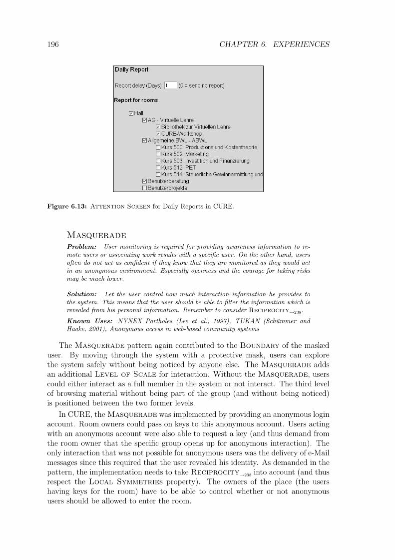
192 CHAPTER 6. EXPERIENCES
Figure 6.11: The Hello Hello pattern as part of the Student Gallery of CURE.
6.4.3 A sequence addressing privacy and group formation
This third sequence extended the last two sequences in order to provide privacy(and group formation support). It is a good example to show how the evolutionaryapplication of the patterns resulted in structure preserving transformations thatincrease the system’s wholeness.
We can differentiate the patterns of this sequence into two subsequences:
1. The sequence addressing privacy concerns and
2. the sequence addressing group formation.
Both sequences are based on the Room→182
, the Door→183
, and and the Login→181
pattern. It therefore makes sense to have a closer look at how the two subsequenceschanged the level of wholeness. If we use the fundamental properties outlined byAlexander we can observe a certain degree of wholeness that was achieved with theinitial three patterns:
The Contrast and Levels of scale property is strengthened as the Room
distinguishes between users inside a room and outside a room and rooms are per-ceived as small part of a larger whole. Additionally, the Boundaries property is

6.4. DEVELOPMENT ITERATIONS IN CURE 193
enforced in two different ways. On the one hand, privacy for the collaborating usersis introduced, and on the other hand access to the shared objects is limited.
Communication facilities like a mailbox for asynchronous communication and apersistent chat for synchronous collaboration strengthened the Strong center ofcollaboration and increased the Not-separateness of the users.
By applying the Door→183
pattern the Boundaries property was weakened.However, this transformation also strengthened the Not-separateness of theusers, the Levels of scale and the Gradient as transition between global andlocal rooms are possible. Additionally, the Strong center of a place for collabo-ration is enforced as the doors increase the experience of working in rooms.
The Login→181
pattern strengthened the Boundaries property as only userswith a valid identification could enter the system.
The subsequence addressing privacy
Lock and Key
Problem: People feel the need to distinguish public from private places and therebyidentify private objects that are located in the private place. They may want to restrictaccess to private places and the contained private objects so that only familiar userscan access private places and objects.
Solution: Protect private places with locks that can only be opened with matchingkeys. Provide the users with keys that can be used to open locks. Make these keysfirst-class objects that are visible to and portable by the user. Place private propertyinside locked rooms.
Known Uses: Moo, SSH, CURE
The Lock and Key pattern was applied to add access control to the rooms.Before a user was allowed to enter a room, the system checked whether or nothe holds a virtual key to this room. If the user does not have a key, he couldask the key holders of the room to replicate their key and pass on a copy to therequesting user. By adding this kind of access control the Not-separateness ofthe collaborating groups was decreased. However, in contrast to this the Contrast
and the Boundaries property of CURE was strengthened as the separation of thecollaborating groups was increased.
To structure group interaction and to reflect the roles of users in a group theusers requested different keys with different rights, such as the rights to enter aroom, create sub rooms, edit pages, or to communicate within the room. CUREdisplays the different rights by assigning different colors to the private keys of theusers (see fig. 6.12). Due to the different rights a user can have in a group theLevels of scale, Contrast, and Gradient properties were strengthened. TheLevels of scale property increased because it was now possible to model differentkinds of interaction between group members. The Gradient property increasedas users could create keys with gradually increasing rights. User could control howgroup members gradually take more responsibilities. In the beginning of a group

194 CHAPTER 6. EXPERIENCES
interaction a user might, e.g., just be allowed to read the content of a room whileshe later might edit it. The Contrast property was strengthened by the Lock
and Key pattern as each group in the system could now establish its own way ofinteraction.
The Lock and Key→193
pattern together with the Room→182
pattern modelsthe representation of groups in CURE. A group interacts in a room and the groupmembers are all users who have a key for this room (Haake et al., 2004b). Thus groupformation is supported by means of creating rooms and distributing keys for theserooms. A user can have keys to different rooms and thus can be a member of differentcollaborating groups. Thereby, the Lock and Key pattern finally strengthens theDeep interlock and ambiguity property, as groups get connected.
Figure 6.12: Overview of users having a Key for a room in CURE.
As described above, users without a key could ask the owners of a key for apersonal copy. This could probably be modeled without any additional tool support.Since the user can see other users who have a key with sufficient rights for the room,they could send these users a mail that explains their request. The key owner wouldreceive this mail and check if the request makes sense. In a positive case, he wouldcreate a key that matches the user’s needs and inform the requesting user by mailthat his wish was fulfilled.
The problem is that these activities require a complex workflow that has inher-ently several media breaks. Users thus requested an easier way to ask for a key,which was modeled using the Bell pattern.
Bell
Problem: When latecomers want to join a collaborating group, they may intrudethe group’s privacy. The group may feel disturbed by uninvited visitors, or simply notnotice that someone wants to join.
Solution: Provide the meeting place with a bell that allows latecomers to raiseattention regarding their will to participate in the group. Model the bell as an interfaceelement that is associated with the representation of the shared space where interactionof the group takes place. Signal the activation of the bell to the members of the groupand let them decide whether or not they allow the asking user to join the group. In

6.4. DEVELOPMENT ITERATIONS IN CURE 195
both cases, inform the asking user and – if possible – guide the user in the next stepof entering the session (or staying out).
Known Uses: ISDN, NetMeeting (Summers, 1999), FUB (Haake and Schummer,2003)
The bell pattern supports Not-separateness on several levels: (1) on a tech-nical level there is no longer the need to switch between different tools and media forperforming a key request, (2) on a human-human interaction level it structures theway how users interact in a recurring situation (and thus helps to better understandthis process), and (3) on a group level it connects users in a group with users outsidethe group. The bell belongs to both spaces, the space in the room and the spaceoutside the room. It is thus a region with Deep interlock and ambiguity.
In early 2004, many users had access to different rooms. But not all rooms wereequally important for them. For instance, a member of the distributed systemsdepartment had access to a room of the psychology department for assisting thepsychologists in shaping the room’s content from a technical perspective.
But when the seminar in psychology started, the computer scientists was in-formed about all changes to content in the psychology room. Since the developerwas not interested in this information, it distracted him from his other work. Theuser could have canceled his membership in the psychology room, but this was notdesired by the psychologists.
The Boundary of his awareness was too weak so that relevant as well as irrel-evant awareness information reached this user.
The CURE developers added a list of accessible rooms from which the user couldselect those rooms for that he would like to be informed about changes in the dailyreport.
Attention Screen
Problem: Every request for attention needs to be processed by the user. Thus, italready takes some of his attention. But in situations, where the user needs to focushis attention on other things, this is disturbing.
Solution: Enable the user to filter the information which reaches him. Use meta-information (e.g. sender details) or content information (e.g. important keywords)to distinguish important information from not so relevant information. Collect theless important information at a place where the user can process it on demand andforward relevant information directly to the user.
Known Uses: Siemens S55, Mozilla Junk Mail Filter, TeamSpace (Fuchs et al.,2001), WebWasher, Instant Messaging Systems like MSN Messenger, ICQ, AIM, orJabber
The Attention Screen adds another Gradient to the Boundaries of eachuser. The properties mutually contribute to one another. With the Attention
Screen, the user can gradually block information to which he still has active access(the user still can go to the room and look for new pages).

196 CHAPTER 6. EXPERIENCES
Figure 6.13: Attention Screen for Daily Reports in CURE.
Masquerade
Problem: User monitoring is required for providing awareness information to re-mote users or associating work results with a specific user. On the other hand, usersoften do not act as confident if they know that they are monitored as they would actin an anonymous environment. Especially openness and the courage for taking risksmay be much lower.
Solution: Let the user control how much interaction information he provides tothe system. This means that the user should be able to filter the information which isrevealed from his personal information. Remember to consider Reciprocity
→238.
Known Uses: NYNEX Portholes (Lee et al., 1997), TUKAN (Schummer andHaake, 2001), Anonymous access in web-based community systems
The Masquerade pattern again contributed to the Boundary of the maskeduser. By moving through the system with a protective mask, users can explorethe system safely without being noticed by anyone else. The Masquerade addsan additional Level of Scale for interaction. Without the Masquerade, userscould either interact as a full member in the system or not interact. The third levelof browsing material without being part of the group (and without being noticed)is positioned between the two former levels.
In CURE, the Masquerade was implemented by providing an anonymous loginaccount. Room owners could pass on keys to this anonymous account. Users actingwith an anonymous account were also able to request a key (and thus demand fromthe room owner that the specific group opens up for anonymous interaction). Theonly interaction that was not possible for anonymous users was the delivery of e-Mailmessages since this required that the user revealed his identity. As demanded in thepattern, the implementation needs to take Reciprocity
→238into account (and thus
respect the Local Symmetries property). The owners of the place (the usershaving keys for the room) have to be able to control whether or not anonymoususers should be allowed to enter the room.

6.4. DEVELOPMENT ITERATIONS IN CURE 197
The subsequence addressing group formation
The patterns discussed in the previous subsequence focussed on providing users witha private and safe place. However, users should also be supported in finding oneanother in order to initiate collaborative work. The following patterns weaken theprivacy to better support group formation.
Since CURE is a learning platform it is often important that the users act inan authentic way. Authenticity is an important issue when building trust. Trust isimportant if the users take the risk of failure. And failure is an important aspectin learning activities. Building an authentic and trusted relationship between userswas therefore considered as an important issue in the design of CURE.
Virtual Me
Problem: Account names used by users of a collaborative application are often notvery expressive. Especially, an account name is only a short textual representation ofthe user. In a large user community, account names look similar. But users need tocommunicate their identity in order to interact with other users.
Solution: Allow the users to play theater! Provide them with means to create avirtual identity that represents them while they act in the system. Show the virtualidentity when the user is active.
Known Uses: Textual characters in MUDs, VITAL (Pfister et al., 1998), WEBHomepage
The Virtual Me pattern only partially addressed this need since users shouldact in a realistic way. Their theater play should not be too far away from reality.However, the other parts of the pattern apply to CURE. Users should be able topresent themselves to other users. To foster authenticity the users could provide aphotography. They could also present a short text describing themselves.
Up to now, 38% of the user population (515 of 1341 users) made use of either atextual description or a photography. Notably, female users showed a higher willing-ness to present themselves (41% vs. 37%). The difference is even more significantif we compare the percentage of users who contributed both a picture and a text.Here, 25.7% of all female users provided both kinds of information while only 20.5%of the male users provided both a picture and a text. Male users were more eagerto provide only a picture (6.3% male vs. 1.9% female).
The Virtual Me pattern established the users as additional Strong cen-
ters besides the rooms and the edited content. Having a picture and/or a textualdescription helped to focus on the users.
With this in mind, the SIG members demanded additional means for connectingthe users. The asked for an interesting way to find out more about the users of thesystem.
User Gallery
Problem: If more than one user interacts with shared data, it is hard to coordinatethe interaction - especially with strangers. Without knowing who is using the system,it is hard to establish collaboration or to become aware of other users’ activities.

198 CHAPTER 6. EXPERIENCES
Solution: Provide a list of all users who are members of the community. Let themembers provide personal information in this list that is related to the community’stask. Design this list in a way that it is interesting to browse.
Known Uses: VITAL (Pfister et al., 1998), ChiPlace (Girgensohn and Lee, 2002),Community web sites like www.communities.com
In CURE, the User Gallery was modeled as a special room, the Student Gallery(fig. 6.14).
Figure 6.14: Parts of the Student Gallery in CURE.
Unlike other rooms, the student gallery does not list wiki pages but shows theself descriptions of the registered users. It was important that all users were shown(especially in the early phases of system use where the user community was relativelysmall). The Student Gallery should bring together students from different facultiesand foster exchange between any students of our university. With respect to theproperties of wholeness this emphasized Deep interlock and ambiguity andincreased Not-separateness.
Another option for moving the individual user into the focus was the Interac-
tive User Info pattern:

6.4. DEVELOPMENT ITERATIONS IN CURE 199
Interactive User Info
Problem: Users are able to associate the awareness information with the artifact,but it is still difficult to find out how to launch appropriate collaborative tools (e.g.for opening a chat tool with the confocal user – cf. Talk first
→242).
Solution: Make the user representation interactive so that another user can revealmore information on the shown user or start tighter collaboration with the user byacting on the user’s representation.
Known Uses: IM Buddy Lists
This pattern was implemented by linking all visualizations of user names to theirVirtual Me. Static information like the Change Warning
→228at the bottom of
each page thus became active. Content was related to real users. The visualizationsof the self descriptions were additionally enhanced by providing mail links to theusers. Establishing a contact with the author of an artifact was thus eased.
The Interactive User Info helped to increase Not-separateness andStrong centers.
One problem with the User Gallery is that it does not scale well. If thenumber of users grows too large, the list of the User Gallery will also growaccordingly. When the system had approx. 300 users, the users had problems tofind relevant peers in the Student Gallery. They asked for filtering regarding theirinterests and selected the Bird of a Feather pattern.
Birds of a Feather
Problem: If people don’t know one another it is hard to decide who could be a goodpartner for a collaborative activity. For co-located situations, humans have developedintuitive strategies (based e.g. on visual clues) that help them to select whom theyshould contact if group formation is needed. In distributed work environments thepresence of other users is often reduced to their user name. This makes it hard tofind another user for a collaborative activity.
Solution: Compare user profiles or interaction histories to identify two users whoshare big parts of their history. Propose these users as collaboration partners.
Known Uses: MEMOIR (Pikrakis et al., 1998), Autonomy CEN (Autonomy, 2002),Yenta (Foner, 1996), BoF-Sessions at Conferences, Collaborative filtering systemslike the book recommendations at Amazon or the music recommendations in Ringo(Shardanand and Maes, 1995).
The pattern was implemented based on the rooms to which a user has a key.A user can select that he only wants to see users that share a common key withhim (fig. 6.15). This ensures that there is at least one group in which both usersparticipate.
This pattern helps to connect users with comparable interests. It extends thecenter of each user to an even Stronger Center in the social network of users.It further helps to increase Not-separateness since it brings together users withshared interests and it helps to define Boundaries encapsulating members of the

200 CHAPTER 6. EXPERIENCES
Figure 6.15: Filtering Birds of a Feather in the Student Gallery.
same interest groups. However, we should note that these boundaries are person-alized and therefore allow Deep interlock and ambiguity of each individualuser.
The last pattern of this sequence is the Visa pattern:
Visa
Problem: While the protection of group interaction by explicit Logins protects thecommunity it also makes it difficult for non group members to interact with groupmembers. Especially, if there exist some (e.g. social or business) reasons why thosenon group members of the system cannot become permanent group members, interac-tion is not possible.
Solution: Offer the users of the system a possibility to grant visas (temporary useraccounts) to non-users of the system.
It bridges the gap between group formation aspects and privacy aspects by allow-ing temporary access to group resources. In CURE, the Visa pattern was modeledby means of time keys. Group members can decide to pass a time-restricted key toanother user. They can define a start date and an end date. Within these dates thekey will allow the key holder to access the associated group room.
Such keys were, for instance, used for presenting results of a work group. Themembers passed keys for the presentation week to other interested users. Beforethat week, they cleaned up their room in order to have only documents in the roomthat they could show to other users. The visitors were then able to inspect theroom. After the keys became invalid again, the group could continue the internalactivities.
The Visa pattern helps to increase Not-separateness. It also provides Gra-
dients since one can provide limited access to specific users. Finally, it helps tokeep Boundaries intact since the room will be shielded again after the keys becameinvalid.

6.4. DEVELOPMENT ITERATIONS IN CURE 201
Levels
of
Scale
Strong
Centers
Boundarie
s
Deep
Interlock
&A
mb.
Contrast
Gradie
nts
Not-S
eparateness
Local
Symmetrie
s
Whole
nes
sIn
crem
ent
Login 1 1Room 1 2 1 1 5Door 1 1 -1 1 1 3Lock and Key 1 1 1 2 1 -1 5Bell 1 2 3Attention Screen 1 1 2Masquerade 1 1 1 3Virtual Me 1 1User Gallery 1 1 2Interactive User Info 1 1 2Birds of a Feather 1 1 1 1 4Visa 1 1 1 3
Total Wholeness 4 4 7 4 3 4 7 1 34
Table 6.1: Estimated values for wholeness in the considered pattern sequence.
Evolving Wholeness
The two subsequences described in the above sections let wholeness emerge. We haveshown that each pattern helped to strengthen some of the fundamental propertiesdefined by Alexander. Using Alexander’s measure of wholeness (p. 27), we canprovide a rough estimate for the total level of wholeness after each pattern was tookinto place (cf. table 6.1).
These estimates help to compare the structure before and after the pattern wasapplied. As Alexander pointed out, there is no exact measure for wholeness. Instead,we take a simple approach where we consider each distinct functional increase ofwholeness as an increment of one. For the example of the Login
→181pattern, we
stated that it increases the Boundaries. We count this as an increment of 1. TheRoom
→182pattern also increased the Boundary property. But in this case the
Boundary was enforced on two levels; the artifact level and the interaction level.We therefore place an increment of 2 in table 6.1. In two cases, properties wereweakened which is shown as a decrement in table 6.1.
The last column of table 6.1 shows the increment of wholeness added by eachpattern. The last line of the table shows the total wholeness after the applicationof all patterns from the sequence. The evolution of wholeness is shown in figure6.16. The assumption was that the wholeness measure would increase in a structurepreserving transformation. This could be observed in the analyzed sequence.
202 CHAPTER 6. EXPERIENCES
However, the estimates are based on interpretation of the sequence. They cannotserve as an exact scientific measure. Instead, they are one step in understanding howpatterns contribute to good design. It is also not appropriate to ask for a thresholdabove that a system is complete or whole. Whether or not a system is whole enoughstill needs to be decided by the end-users.
Leve
ls o
f Sca
le
Strong
Cen
ters
Bou
ndar
ies
Dee
p In
terlo
ck a
ndAm
bigu
ity
Con
trast
Gra
dien
ts
Not
-Sep
arat
enes
s
Loca
l Sym
met
ries
Login
Room
Door
Lock and Key
Bell
Attention Screen
Masquerade
Virtual Me
User Gallery
Interactive User Info
Birds of a Feather
Visa
0
1
2
3
4
5
6
7
level ofwholeness
time
Figure 6.16: The evolution of wholeness in the considered pattern sequence (different colors/shad-
ings represent different levels of wholeness in the graph).
6.4.4 Results from the Development Iterations
The experiences from the development iterations show that the development teamand the end-users were able to perform the iterations as described in the OSDP.One problem was the test coverage. The developers were eager writing code thatimplements the patterns and often wrote only partial test cases. Especially at theend of the first project period (after 12 months), the developers tried to implementend-users’ task cards in order to provide the most comprehensive system functional-ity. The problem with this approach was realized in the second half of the project.Especially in the last quarter of the project missing tests showed to be critical. Inthis part of the project, the persistence layer of the system had to be changed inorder to satisfy external requirements for the production phase of the system.

6.4. DEVELOPMENT ITERATIONS IN CURE 203
The adaptation of the persistence layer showed to be one of the most problematicchanges during the project life cycle. The group responsible for running the systemin production mode had the requirement that the data, which was stored in a filesystem before, should be stored in a data base. To change the persistence, allpersistent objects had to be mapped to the database system. Performance droppeddramatically since objects were kept in memory before and the developers madeheavy use of object associations, which are not as cheap when mapping objects to arelational database.
The problems with the persistence layer could have been avoided if the membersof the group responsible for running the system in the production mode were partic-ipants in the SIGs. Unfortunately they were not involved in the teaching activitiesand therefore not very interested in participating in the early phases of the project.Insisting on participation of these users would have been important for the project.
Another problem overseen by both, developers and other SIG members, was theperformance of the communication mechanisms. One reason for this is that thedevelopment team initially tried to make use of a java servlet framework that is nottuned to synchronous message exchange (with a high message rate).
These two technical problems – persistence and performance of synchronous com-munication channels – slowed down the team in the last third of the project. Userstories could not be delivered as fast as in the first two thirds of the project. Thishad the effect that users also reduced the number of stories that they brought in.We can thus observe that a fast response to user requirements motivates users tothink about possible improvements more frequently. The fast delivery of functionalincrements is vital for a high end-user participation.
The requirements of chapter 2 were addressed in the following ways:
– Wholeness (R1) was demonstrated in section 6.4.3. The pattern sequences ledto wholeness regarding the properties proposed by Alexander. In addition, theexisting tests ensured that existing functionality remained intact when addingextensions. However, as discussed above, the tests were not as comprehensiveas needed.
– Structure-Preserving Transformations (R2) were achieved by applying se-quences of related patterns. The effect of one structure-preserving transfor-mation was demonstrated in fig. 6.16.
– Reflection (R3) took not place to a large extent since it was rather an issuein the tailoring iterations. The only phase where reflection played a role waswhen the backlog was reordered and the relation between backlog and theexisting system was examined.
– Process awareness (R4) was limited in the early phase of the project sincethe end-users of the SIGs had only limited access to the project’s backlog.However, it increased as soon as the end-users could access the backlog fromwithin CURE.
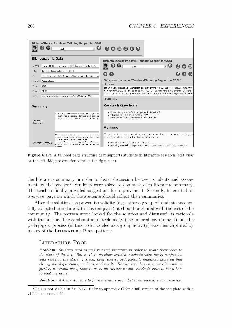
204 CHAPTER 6. EXPERIENCES
– Iterative Design (R5) took place since the development team frequently re-leased new versions of the system. One example, where the iterations changedearly design decisions, was the shift from a Shared Folder metaphor to theRoom metaphor.
– The task cards of the backlog helped developers and users to focus on oneproblem at a time (R6). Actually, when most task cards were completed, thedevelopment team released a new version of the system.
– Forces were examined with the help of relations between patterns (R7 and R8).The patterns often helped the developers to also consider related problems.
– End-user involvement (R9) was most intensive in early development iterations.The users actively contributed to the design and proposed the application ofspecific patterns. In the case of the Life Indicator
→190, they even brought
in new patterns.
– Education of users and developers (R10) was an important issue throughoutthe development iterations. The patterns were used as one means for trans-ferring design knowledge. This was complemented with traditional forms ofknowledge transfer, especially the exchange between the experienced developerand the users or the peer developers. If no experienced developer would havebeen in the team, the role of the patterns would have been different.
– The explicit consequences (R11) of the patterns triggered discussions regardingthe involved pitfalls of a solution.
– Integration (R12) was addressed by using a combined backlog of the differentSIGs. In addition, the CURE system was integrated with the current learningmanagement system of the university.
– End-User development (R13) was not addressed in this type of iterations. Thedevelopment tasks were all performed by the developers since they requiredprogramming. However, the basis for end-user tailoring was laid by the devel-opment team (since this was requested as an orthogonal requirement by theusers).
– Finally, new pattern ideas were brought in that were shared between the users(R14) and which found their way into the group’s pattern catalogue. Thequality of these solutions is still evaluated (R15).
The resulting system was widely accepted by the users. The user communitygrew constantly from the first voluntary use by students. Students and teachingstaff spread the word about the system and other students and teachers started touse the system as interaction platform. After 18 months of regular use, the systemhas reached a user population of 1393 users (all of them used the system on avoluntary basis).

6.5. TAILORING ITERATIONS IN CURE 205
6.5 Tailoring Iterations in CURE
The role of the tailoring iterations became important in the latter parts of theproject. After users used the system for a longer time, they started to reflect onsystem use and on interaction patterns that recurred in their interaction. The timespan between the first login and the first tailoring action varies. Some power usershave started to tailor their room after approx. one month of system use while otherusers never tailored the system.
We could observe tailoring at two levels:
– Users established interaction sequences that supported a group process in asub-optimal way. The users did not change the underlying technology butrather the pattern of use. These instances of tailoring were the starting pointfor development iterations. An example that will be discussed below was theimplementation of the Hello Hello pattern.
– Users modified both the process and the underling technology in order toestablish a new way of interaction. These tailoring actions were also triggeredby from patterns of use. But in contrast to the first type of tailoring actions, theusers also thought about modifying the technology using the tailoring facilitiesoffered by the CURE system. Examples are the CURE planning game andthe support for the creation of diploma theses.
We will present the three examples of tailoring in the next two subsections.
6.5.1 The Hello Hello pattern
The department of psychology had longer experiences in teaching virtual seminarsusing “traditional”news-group technology. They had good experiences with a roundof introduction: At the beginning of the seminar the users should introduce them-selves and explain their motivation for the seminar.
In order to conduct a virtual seminar in CURE the psychologists thought abouthow they could reach the same goal in CURE. They understood that the basic formof interaction that they intuitively followed in their news-group seminars was thatof the Hello Hello
→163pattern.
Therefore, they had to define a special welcome area in which the introductioncould take place. The welcome area was defined both by its time (in the early phasesof the seminar) and by its location (a special initial page on which the participantsshould introduce themselves). By providing the users with a location for introducingthemselves and with a phase of the seminar, the social process (how to interact inCURE) was adapted to the specific goal (that of the Hello Hello pattern).
After running more than one seminar it became clear that some parts of thedescription were required for all users. Examples are the user’s name and his pic-ture. The idea was born to have a system-wide representation of these user specificattributes. The Virtual Me
→197pattern fulfilled this goal. The problem was that

206 CHAPTER 6. EXPERIENCES
the users were not in control of a system wide space in which such descriptions couldbe stored and managed. This was the reason why the Virtual Me
→197pattern was
escalated to a development iteration.
The example shows how tailoring of social processes, modifications of patternsof system use, and the emergence of new requirements went hand in hand in atailoring iteration. Patterns played an informative role here. Note that the Hello
Hello→163
pattern was later on also introduced on a system wide level (cf. section6.4.2).
6.5.2 The emergence of CSCL patterns during tailoring it-erations
Another example for end-user driven adaptations of system use was the emergenceof patterns for collaborative learning. Again, the adaptation of a social process wasthe first step.
The context was the process of supporting students in their first larger researchproject, the diploma thesis, which ends their diploma studies. Up to then, thestudents have often not experienced in depth research processes that involve thedefinition of a research agenda, the search for and understanding of relevant liter-ature to capture the state of the art, and the adaptation of the state of the art tothe specific research problem. Especially the search for and the understanding ofthe current state of the art is often not experienced to a satisfying degree by thestudents.
This was the point in time when domain specific patterns came into play: Theusers needed more advice in solving a pedagogical problem, not a technical prob-lem. Several patterns of the pedagogical patterns movement (Eckstein, 1999) cancontribute to the problem of superficial understanding of literature research. Anexample is the Read, Read, Read pattern of Bergin (2002):
Read, Read Read
Problem: To do well in a dissertation5 you need to go deep, but you need enoughbreadth to know how your research relates to the rest of the field and to the rest ofhuman knowledge.
Solution: Therefore, read everything relevant to your research. Read for both depthand breadth. Take notes as you read. Pay special attention to research methodologyas you read. What questions were asked and HOW were they answered.
A first translation of a comparable approach to the domain of computer-mediatedlearning can be found in (Hafele and Maier-Hafele, 2004, p. 167), where the authorsprovide a method for collaborative text summarization:6
Goals:
5Note that Bergin initially proposed the pattern for PhD education. However, the teachers atour university demand the same practice for diploma students.
6Translated from German by the Author.

6.5. TAILORING ITERATIONS IN CURE 207
– The participants look into the subject.
– The participants provide feedback. This enables the teacher to assess, what hasbeen understood by the participants.
– The participants act as mutual experts.
Group Size: 1
Process: The teacher provides learning material in the WIKI.
The teacher asks the students to read the material and create annotations of thefollowing type:
– 5 annotations with links to related material,
– 5 questions focussing on the provided material,
– 3 issues that the participant accepts (with reasoning),
– 3 issues that the participant cannot accept (with reasoning), as well as
– 3 answers to questions stated by their colleagues.
Compared to the model proposed in the Read, Read, Read pattern, the col-laborative text editing introduces a collaborative aspect since it asks the participantsto state questions and answer other people’s questions.
With this background, the teacher started to think about literature search inthe context of diploma theses. His first idea was to better structure the processof literature search (initially without any relation to pedagogical patterns). Hesuggested that the student creates a research room in which the student can collectrelevant literature. In order to receive support, the student could invite the teacherso that the teacher could monitor the found literature and supplement the literaturelist.
The users created pages for found literature but still had problems to structuretheir process. For that reason, a second approach to the problem included a tailoredenvironment for literature collection that explicitly suggests a process. The teacherprovided page templates that structure the relevant information needed for foundliterature, for creating a summary of the paper, and for managing a collection ofpapers.
In the context of this thesis it is not important to go into details of the templatedefinition. The important aspect is that the users define the structure of the contentby providing XML tags that describe the fields that are on a page (cf. appendixC for more details). In the context of the literature review example, the teachercreated a template that guides the student through the process of collecting relevantinformation about the paper. So, in contrast to the use of standard pages that allowfree-form input, the student now has to fill specific fields that are relevant for histask. These fields will be visualized in a form that is close to the intended form ofthe school (regarding citation formats). By that the student also learns how relatedwork should be cited.
Figure 6.17 provides an example of a literature summary page in the edit view(left) and in the display view (right). To embed these new pages in a group process,the teacher did two additional modifications: Firstly, he added a comment field to

208 CHAPTER 6. EXPERIENCES
Figure 6.17: A tailored page structure that supports students in literature research (edit view
on the left side, presentation view on the right side).
the literature summary in order to foster discussion between students and assess-ment by the teacher.7 Students were asked to comment each literature summary.The teachers finally provided suggestions for improvement. Secondly, he created anoverview page on which the students should collect their summaries.
After the solution has proven its validity (e.g., after a group of students success-fully collected literature with this template), it should be shared with the rest of thecommunity. The pattern scout looked for the solution and discussed its rationalewith the author. The combination of technology (the tailored environment) and thepedagogical process (in this case modeled as a group activity) was then captured bymeans of the Literature Pool pattern:
Literature Pool
Problem: Students need to read research literature in order to relate their ideas tothe state of the art. But in their previous studies, students were rarely confrontedwith research literature. Instead, they received pedagogically enhanced material thatclearly stated questions, methods, and results. Researchers, however, are often not asgood in communicating their ideas in an educative way. Students have to learn howto read literature.
Solution: Ask the students to fill a literature pool. Let them search, summarize and
7This is not visible in fig. 6.17. Refer to appendix C for a full version of the template with avisible comment field.

6.5. TAILORING ITERATIONS IN CURE 209
comment the literature. Provide the teacher with access to the literature pool and lethim comment on the student’s summary.
Known Uses: Literature research at the distributed systems department (in thecontext of diploma theses).
Note that the current status of the CURE project is in a phase where firstpatterns are detected by the pattern scout (the Literature Pool pattern actuallywas the first pattern that was found this way). We observed that it requires a longertime until the users begin to tailor and even longer experience until the users areconfident enough to share their solutions within the whole user community. However,we are optimistic that the growing collection of user-made patterns will motivateother users to share their experience as well.
6.5.3 Results from Tailoring Iterations
We observed that tailoring took place according to tailoring iterations. We have alsoshown sequences in which the tailoring operations triggered new tasks for develop-ment iterations. The assumption of the OSDP was confirmed that the iterationscontribute to each other.
The opportunity to tailor motivated users to reflect on their activities (R3).Users created new domain-specific patterns (R14) and provided implementationsusing the tailoring mechanisms of CURE (R13). Some users referred to patterns tosupport their tailoring, but in most cases the tailoring operations were rather basedon intuition. This may be one reason why many users reported that tailoring wasstill difficult.
Propagating the collection of domain-specific patterns to the users is thus stilla challenging task to educate the end-users (R10) and to support better tailoringactions. In cases where patterns were used the forces were also made explicit anddiscussed between the tailoring users (R7, R8, R11). In other cases, the forces didnot play an explicit role.
We could observe that some users reflected on their tailoring actions and thattheir tailoring practice evolved. An example is the case of the Hello Hello pat-tern. However, we could not yet find a general trend for iterative improvement oftailoring practice.
Process awareness (R4) was not yet achieved regarding tailoring. Users insteadtailored on demand. This is part of the tailoring idea. The tailoring user should fixa problem of use during use. This implies that the problem will not be scheduled orplanned.
The other requirements were not addressed since they are not applicable in tai-loring iterations.

210 CHAPTER 6. EXPERIENCES
6.6 Student Projects
To prove the educational quality of the patterns they were used in student thesisprojects. Students selected a groupware development task and received a copy of thegroupware pattern language. They were then asked to structure their applicationdevelopment by means of pattern sequences. The projects were:
CURE expert finder: The student was asked to enrich the collaborative learningenvironment CURE with mechanisms for finding potential co-learners. Theselections of co-learners should be based on the other learner’s expertise. If alearner has a question the co-learner should be able to answer the question.
The task was performed by a Bachelor of Computer Science student at theDistance University of Hagen. It had a duration of 6 months. The studenthad experiences in software development in Java and knowledge in Servletprogramming that helped him in the practical implementation.
During the development, the student applied the following pattern se-quence: Show the Expert
→241→ Pay Back
→236→ Letter of
Recommendation→233
→ Birds of a Feather→199
→ Gaze Over the
Shoulder→145
→ Control Your Privacy→229
→ Hello Hello→163
→Hall of Fame
→232→ Presence Indicator
→135→ Who’s Listening
→245
The resulting system is described in (Cullmann, 2004).
Being asked to reflect on his learning process, he stated that the initial pattern(Show the Expert
→241) was obvious for him and that he had the same
idea without knowing the pattern. However, he also stated that the otherpatterns helped him to reflect on the problem area. He provided a mapping ofthe patterns to his concrete context and finally implemented an expert findersystem.
The expert finder system can be considered as a rather large developmentproject (compared to other student projects like the SCOPE example presentedon page 212). The student based his work on the CURE project that had atthis point of time 383 classes with 64405 lines of code.8 He modified 17 classesby changing/adding 512 lines of code. Considering only the modified classes,he performed changes at 4.4% of the code. He added a new package with meansfor earning and spending expert points and visualizing expertise throughoutCURE. This package contained 34 classes and 3484 lines of code. In total, thestudent modified or added 4000 of 67889 lines of code which is a ratio of 5.9%.
We could observe that the changes weaved through the project (changing onlysmall methods of existing classes). The patterns helped the student to under-stand which changes he had to perform.
The examiner of the project rated the student’s solution as a good design.The modifications reflected the essence of the patterns. The solution was
8The metrics presented for the project shall only provide an impression on the project’s sizeand complexity.

6.6. STUDENT PROJECTS 211
well integrated with CURE. So, we can conclude that the student learned tounderstand and apply the patterns.
Collaborative Web research: The student was asked to integrate mechanisms inCURE that support a group of students in finding research literature on theWeb. He was a diploma student of computer science at the Distance Universityof Hagen. The student was familiar with java technology. He was not familiarwith the concept of design patterns.
Figure 6.18: A student’s mock-up of a system supporting collaborative Web research.
In a set of conceptual iterations the student selected high level and lowlevel patterns that he considered important for his task. The patterns

212 CHAPTER 6. EXPERIENCES
were: Awareness Proxy→226
→ Elephant’s Brain→150
→ Remember to
Forget→238
→ Gaze Over the Shoulder→145
→ Local Awareness→127
→ Time Compressor→242
→ Semantic Distance→240
→ Semantic
Net→240
→ Active Neighbors→225
→ Presence Indicator→135
→ Swarm
and Collect→241
→ Distinct Awareness Info→229
→ In-Place Aware-
ness View→233
→ Letter of Recommendation→233
→ From Shared
Data to Shared Work→120
.
At the end of the conceptual iteration the student created mock-ups thatvisualized his transfer of the patterns to the context of CURE (cf. fig. 6.18).At the time of writing of this thesis, the student is still performing developmentiterations in order to implement the functionality outlined by the mock-up. Wecan, thus, not report on the complexity of his solution. However, he also basedhis project on CURE which had 601 classes and 132756 lines of code.
The examiner was asked to asses the results of the conceptual iterations. Hewas convinced that the proposed extensions of CURE could help to supportthe task of collaborative Web research. Especially the selection of recommen-dation mechanisms was considered as promising. The student reported thatthe patterns helped him in better understanding the task of groupware devel-opment.
The collaboration-aware software development environment SCOPE:The student was asked to enrich the Java software development environmentEclipse (OTI, 2003) with mechanisms for providing group awareness andreducing conflicting work. The Eclipse environment includes a connection tothe version management system CVS (Price, 2000). It also allows to comparethe local workspace with the versions stored in the CVS. The problem is thatdifferences between the group members’ workspaces cannot be detected untilone user decides to check in his changes. And even then, other users are notinformed immediately after the check in that newer versions of the code wereavailable. The student was asked to enrich the interaction between developersso that they become aware of other users’ changes and activities as soon asthey take place.
The task was performed by a diploma student of computer science at theUniversity of Dortmund. The student had superficial knowledge in Java de-velopment technologies and was employed to get familiar with the Eclipseenvironment before he started to work on his diploma thesis. He had no ex-perience with the development of distributed systems. The student worked onthe project for 12 months (of which approx. 8 months were spent on tryingto understand the Eclipse platform). The customers were developers of theDistributed Systems Department of the FernUniversitat in Hagen. They usedEclipse on a daily basis and felt the need for more group awareness to avoidconflicting work.
During the project, it became clear that the student had problems in manag-ing the task of software design. Especially the mapping of discussed designstructures to code was difficult for him.

6.6. STUDENT PROJECTS 213
He applied the following patterns (without an obvious pattern sequence):
– From Shared Data to Shared Work→120
– Local Awareness→127
– Gaze Over the Shoulder→145
– Elephant’s Brain→150
– Proxy Object→237
– External Awareness View→231
– Change Warning→228
– Centralized Objects→228
– Mediated Updates→236
From an expert’s perspective, the student did a good job in selecting thepatterns. But due to missing experience in software development, a seconddeveloper (acting as a mentor) would have been needed during the implemen-tation.
Finally, he implemented 17 classes with 2115 lines of code to visualize changewarnings and track changes. In addition, he modified three classes of theEclipse CVS client in order to implement the Gaze Over the Shoulder
→145
pattern.
The resulting system described in (Jaabari, 2004) provided first support mech-anisms for visualizing Local Awareness in the Eclipse environment.
6.6.1 Results from the Student Projects
The student projects all showed that the patterns can be used to educate developersin the context of developing collaborative applications (R10). All three studentsreported that the patterns supported them in their process of interaction design.
The patterns were applied very differently by the different students. The reasonfor this was mainly that each student had to embed the patterns in different appli-cation contexts. However, the patterns showed to provide guidance for all differentapplication contexts (R12).
The focus of the projects laid in the development iterations (although the lastproject spent a long time performing conceptual iterations). The patterns helped thestudents to focus on one problem at a time (R6) although the capability of under-standing the interplay of different patterns (R7) depended on the developer’s level ofexpertise. Especially trained software developers profited from the patterns, whilethe untrained developer had problems in creating a design based on the pattern’sadvice.
All students managed to provide working software systems that included theselected patterns although the students performed differently well regarding to theirexpertise in software development.

214 CHAPTER 6. EXPERIENCES
The experiment was focussed to only investigate the educational value of thepatterns. Therefore other requirements addressing user involvement, wholeness, andreflection were not analyzed.
6.7 Observations Made by Peer Reviewers and
Shepherds
The OSDP has been commented and reviewed by reviewers of the XP2004 con-ference (Schummer and Slagter, 2004). The feedback was positive with regard tothe possibility that the process could foster end-user participation. One anonymousreviewer, e.g., commented the focus on end-user development as follows:
I think that end-user participation is an incredibly important idea that few will haveconsidered. [...] If developers gave up“considering” the needs of real users and insteadbrought those users into the process we would have fewer terrible systems and moregood ones. In particular we might avoid many of the attacks on personal privacy andautonomy inherent in many large systems. I applaud this effort.
Critical comments focussed on the additional structure that the process requests.Since agile methods argue to put people over processes and tools, this attitude couldhave been expected. Other reviewers asked for more details regarding experienceswith the process, which shows that an expert rating of only the process is verydifficult without having an example of how the process was applied. However, theexperience described before in this thesis provides evidence that OSDP can be ap-plied successfully.
The patterns of the groupware pattern language have partially undergone a rig-orous review process. They were submitted to annual EuroPLoP conferences in theyears 2002–2005. The reviewing process of EuroPLoP is different compared to thatof other conferences with respect to the interaction between reviewers and authors.After the author submitted an initial version of the pattern collection, he is pairedwith a shepherd, an experienced pattern author. The shepherd has the task of ask-ing his sheep (that’s how the author is called in the process) challenging questionsin order to make the pattern submission more clear and valid. The sheep’s role isto rewrite the paper in a way that the questions do no longer emerge from the pa-per. Instead of defending the own work the author should think about changing therepresentation (and sometimes also the content) to make it clearer for the audience.A pattern language for shepherding that helps to structure the interaction betweensheep and shepherd is used by most shepherds (Harrison, 1999).
At the end of the shepherding process, the pattern collections have to pass aquality gate. The shepherds and associated program committee members discusswhether the pattern collection is mature enough to be discussed at the conference.
For EuroPLoP 2005, e.g., the program chair Andy Longshaw proposed the fol-lowing questions that a pattern collection has to pass before it can be accepted fora writer’s workshop:

6.7. OBSERVATIONS MADE BY PEER REVIEWERS AND SHEPHERDS 215
– What is the target audience for this paper? Is it clearly identified?
– Does the problem feel like a real problem? If not, why not?
– Is the context well framed, and does the pattern identify the key aspects (forces)associated with the problem? Are there sufficient forces to support the problem(guideline of four simple statements or two “...but...” statements)? Do theforces pull in opposite directions? What else ought to be discussed?
– Does the solution match the problem? Does it convince? After reading thepaper, are you better prepared to tackle the problem?
– Do the patterns relate to each other? Are sequences described where severalpatterns are involved before a satisfying outcome is reached?
– Does the format help to communicate the key pattern elements?
– Is the writing clear and adequate for the intended audience?
– Does the paper make a sufficient contribution to the patterns body of knowledgebeyond what is already there?
– Would the community benefit from finding this pattern in the EuroPLoP pro-ceedings?
– Have the authors been open to feedback? Did the communication during shep-herding flow well, and induce significant changes?
– Would you like to workshop this paper?
This list of questions reflects the understanding of quality in the EuroPLoPcommunity. There is a large focus on the form. Patterns have to make a tensionbetween forces explicit and they have to provide a solution that feels as if it wouldreduce the tension. This understanding is very close to Alexander’s view of qualityand validity as a phenomenon that has to take personal feelings evoked by theproposed structure into account.
At the conferences, the pattern collections go through another review process.In writer’s workshops the patterns are discussed by a group of 5–10 other patternauthors. The difference to traditional conferences is that it is not intended that au-thors defend their work. Instead, other authors who have read the paper commenton aspects that the author should keep and issues that would require improvement.The author becomes a fly on the wall and carefully listens to the advice given con-currently by the other members of the writer’s workshop. Controversial perceptionsof the pattern collection become obvious and conflicts with other participant’s ex-perience are made explicit. As in the shepherding process, it is again the goal tobetter understand how users of the pattern language would understand and applythem. This provides evidence wether or not the patterns could result in the desiredchange of the context.
In a post-conference phase the author is requested to rewrite the pattern collec-tion again in order to reflect the comments from the writer’s workshop. Finally, adecision on publishing the paper in the conference proceedings is made.
A comparable format was used at the CHI2004 workshop on Human-Computer-Human Interaction Patterns (Schummer et al., 2004).
In detail, the following pattern collections were shepherded and reviewed inwriter’s workshops (with increasing levels of abstraction):

216 CHAPTER 6. EXPERIENCES
Patterns for Managing Shared Objects (Lukosch and Schummer, 2004b):Centralized Objects
→228, Replicate for Speed
→239, Replicate for
Freedom→239
, Guess What I Need→232
, Update Your Friends→243
, Me-
diated Updates→236
, Believe in Your Group→227
, Don’t Trust Your
Friends→230
, Detect A Conflicting Change→229
, and Lovely Bags→235
.
Patterns from the Activity Awareness Family (Fernandez et al., 2003): Re-
mote Viewport→239
, Telecursor→242
, and Remote Selection→239
.
Patterns for Session Management (Lukosch and Schummer, 2005)9: Collab-
orative Session→228
, User List→141
, Invitation→233
, Bell→227
, Don’t
Disturb→229
, and Lights off→234
.
Patterns for Virtual Places (Schummer et al., 2005)9: Room→182
, Door→183
,Map
→184, Lock and Key
→193, Visa
→200, and Locomotion
→234.
Patterns for Computer Supported Dynamic Collaboration (Schummer,2004a): Local Awareness
→127, Presence Indicator
→135, Change
Warning→228
, Active Neighbors→225
, Gaze Over the Shoulder→145
,Elephant’s Brain
→150, and Semantic Net
→240.
Patterns for Filtering Personal Information (Schummer, 2004c):Masquerade
→196, Attention Screen
→195, Buddy List
→227, Birds
of a Feather→199
, Reciprocity→238
, and Who’s Listening→245
.
Patterns for Building Communities (Schummer, 2004b): User Gallery→197
,Hello Hello
→163, Letter of Recommendation
→233, Activity
Counter→225
, Find the Guru→231
, Pay Back→236
, Group Award→232
,Hall of Fame
→232, and Travel Together
→243.
For these 47 patterns, we can assume a good maturity. The other patterns from thecollection were not yet shepherded.
6.8 Summary
In this chapter, we have provided evidence for the validity of OSDP and the group-ware pattern language using four complementary methods.
The applicability of OSDP has been demonstrated by conducting a field studyin which a team applied the OSDP and used the groupware patterns for a two-yearproject. The resulting system was welcomed by the users and is currently used bymore than 1300 users. Feedback from the users expresses a high level of acceptance.Users reported that the system well supported their interaction in collaborativeteaching and learning.
We could observe that the conceptual iterations were performed as anticipated.The participatory nature of these iterations let four SIGs emerge that collaborated in
9The collection is currently in the shepherding phase.

6.8. SUMMARY 217
the following development iterations. The SIGs continued to steer the developmentprocess by actively contributing to and observing the project backlog. Sharing thebacklog over the internet was considered as helpful by distributed SIGs.
In tailoring iterations, the users created and shared adaptations of the system.The use of patterns in this phase was not as high as expected. However, the collectionof tailoring patterns is currently evolving and distributed among users.
During the development iterations, several patterns were implemented in thesystem. New patterns were discovered by the SIGs and added to the groupwarepattern language. The temporal sequence of applying the patterns provided hints onhow structure preserving pattern sequences may look like. Several of these sequenceswere followed in parallel.
The requirements were addressed to a different degree in the different iterationsof OSDP. The combined picture shows that all requirements can be satisfied in aproject that is structured according to the OSDP.
Theoretic considerations provided indications that the sequences of patterns werestructure preserving and contributed to the system’s wholeness.
The educative value of patterns has been tested in three student projects. Whileall students reported that the patterns helped them to better understand the prob-lem domain, the ability to apply the patterns was different. Students with moreexperience in the design and implementation of software systems performed betterthan students without experience. Patterns should thus not be considered as a sil-ver bullet for educating novices to act as software developers. As long as there is adevelopment activity required, the developers need to be trained both in the patternlanguage and in the development language.
The maturity of the patterns as well as the potential of the OSDP have furtherbeen evaluated by different reviewers. 47 of the patterns went through a shepherdingprocess and writer’s workshops in order to make them more mature.

218 CHAPTER 6. EXPERIENCES

Chapter 7
Conclusions and Future Work
7.1 Summary
End-user involvement is one of the most important but much too often neglectedissues in groupware development. Within this thesis, we have presented a develop-ment process that addresses this shortcoming. From a theoretical view on design, wederived 15 requirements for an ideal groupware development process that is basedon an active role of the users. The basis for the requirements was a holistic view ondesign, as it is currently propagated by many designers, especially by ChristopherAlexander. In his view, a holistic approach to design has to be combined with anevolutionary process and focus on end-user education in order to empower the end-user to play an active role in the development process. Together with Heidegger,Alexander puts special attention on the situatedness of design. Users should reflecton their activities whenever their flow of action is disrupted. This situated reflection(as it was also propagated by Schon) provides the best access to the requirementsand supports solutions that meet the requirements.
We showed how the theories of Alexander (most important pattern-driven de-sign, end-user participation, and iterative development in piecemeal iterations) canbe found in many contemporary software development processes. Especially agilemethods provide a valuable contribution to iterative processes that preserve andenhance the wholeness of the system built. These processes advocate that the cus-tomer is the driving force in the development process and that he can control theprogress of each small development increment. However, agile processes put onlylittle interest on the question of how the end-user can be empowered to make sounddesign decisions.
Patterns fill this gap since they are educative tools for teaching non-experts todo good design. We discussed several pattern approaches ranging from a technicalview on patterns to the human-compute interaction centered view of HCI patterns.The latter are presented in a form that is understandable by the end-user. They cantherefore help the end-user while participating in the development process.
In a second step of this thesis we studied current groupware development pro-cesses in order to understand how they make use of software development techniques
219

220 CHAPTER 7. CONCLUSIONS AND FUTURE WORK
in order to integrate the end-user in the development process. Although some au-thors have proposed to adapt iterative and agile processes to the domain of group-ware development, we could not find processes that heavily focus on educating theend-user. Approaches, which meet many of the requirements, include an extendedeXtreme Programming process that focuses on involving the user community in plan-ning and development (instead of just a single customer representative in XP), andan iterative process (based on the STEPS process model) that puts special attentiontailoring during system use. They demand that the end-user adapts the system inorder to meet requirements that evolve from reflection in action.
The main deficit in the state of the art is that no approach meets all requirements.We identified two clusters of approaches: Firstly, a cluster addressing traditionalprocess requirements like process awareness (R4), iterative design (R5), or reflection(R3). Secondly, a cluster addressing issues of end-user involvement (R9), educationin design (R10), and sharing of best practices (R14). In order to support the end-usercentered development of groupware applications we proposed to combine approachesfrom both clusters.
We proposed an agile development process – the Oregon Software DevelopmentProcess (OSDP) – that combines techniques of eXtreme Programming and Scrumwith a pattern approach. The combined process meets all requirements.
OSDP is tailored to the process of groupware development with respect to thestyle of the groupware pattern language used and the process of end-user involve-ment. Groupware patterns have to be written on a very high level of abstraction.Instead of focussing on technical details (which would lead to a technology drivengroupware development) they have to focus on interaction between users and howthis interaction is mapped to the computer-mediated context. The involvement ofthe end-user focuses on embedding the process of reflection in the daily use of the col-laborative environment and resolving break situations in the groupware system. Allusers instead of just one user should be empowered to steer the flow of developmentof the groupware application. All users should be able to tailor their application andshare the tailoring results with others. And all users should contribute to a growingbody of knowledge regarding the tool construction and use for their problem domain.
OSDP structures the development of the application in three kinds of iterations:
– In conceptual iterations users and developers collaborate in scenario interestgroups in order to collect and refine scenarios of system use. They make use ofgroupware patterns to inform their mapping of social processes to a groupwaresetting.
– Development iterations focus on the implementation of the scenarios from con-ceptual iterations. Users and developers collaborate to create task descriptionsand to relate these descriptions to groupware patterns. These descriptions arecollected and estimated regarding their costs and benefits. The developmentteam continuously focuses on the most important tasks in order to implementthe most critical aspects first. Important aspects of the development iterationinclude that the list of tasks – the backlog – is made public in the user com-

7.2. MAIN CONTRIBUTIONS 221
munity and that the task wishes of different users or SIGs are ordered andmerged.
– In tailoring iterations users reflect on their groupware use and fix conflictingforces by adapting the groupware system. Pattern scouts encourage the usersto share their adaptations with other users. If the adaptation matured it isformulated as a pattern and added to the community’s pattern language.
We argued on a theoretical level that the process meets all requirements. Werelated each technique used in OSDP to the requirements and showed how it sup-ported the requirements in other process models. OSDP therefore fills the gap ofa combined process model that addresses traditional development process issues aswell as end-user involvement, education, and sharing of best practices.
Patterns play an important role in the whole process since they are the meansfor communicating design knowledge between users, developers and between usersand developers. For that reason we presented a still evolving groupware patternlanguage and provided example patterns from the pattern language for supportinggroup formation based on enhanced group awareness.
The validation of the approach in real-world projects as well as student projectsshowed that groups ware able to follow the proposed process and that the patternsplay an important role in the communication between all stakeholders. We observedthat users were able to play an active role in all phases of the process. They shapedtheir environment and developed new best practices (e.g., practices for tailoringin order to support literature research). First of these practices were captured aspatterns.
However, the process and the patterns are no silver bullets.
Patterns with a high level of abstraction can often be implemented by tailoringthe application. However, low level patterns still require development and designexpertise by the involved software developers.
The involvement of the user is another critical aspect. The user takes a veryresponsible role in OSDP. He has the power of controlling most aspects of the de-velopment process. However, if he does not steer the process it will very likely flowinto directions that do no longer fulfill all user requirements. In addition, the re-sponsibility of the customer requires new ways of thinking about project contracts.Projects can no longer assume that the development team will implement a fixedset of features in a fixed time frame for a fixed budget. Instead, users have to agreeto be in charge of all these aspects for each small increment.
Being aware of these danger spots we can, however, summarize from the expe-riences that all requirements are addressed by the combination of the OSDP andgroupware patterns.
7.2 Main Contributions
It is now time to restate the main contributions. They are:

222 CHAPTER 7. CONCLUSIONS AND FUTURE WORK
– the introduction of the Oregon Software Development Process that fosters end-user participation,
– a new format for design patterns that is especially focussed on end-users,
– a pattern language for group formation based on enhanced group awarenessand the presentation of selected patterns in an elaborated format,
– a collection of thumbnails of additional patterns from a pattern language forgroupware development,
– a case study of applying the process and the patterns in a participatory designprocess of the collaborative learning platform CURE, and
– the evaluation of pattern languages regarding the role of structure preservingtransformation in the context of the CURE project.
It is up to the reader to be convinced by now. Time will show if the contributionsput end-user centered groupware development forward.
7.3 Future Work
As in every research work, one study opens up many new questions. We concludethis thesis with some open issues that could be addressed in future work.
Most important, we hope that this work will help to focus the different activi-ties in the field of groupware patterns research. The goal would be that a holisticgroupware pattern language would be created by experts from the community. Thispattern language should be completed in order to cover the whole area of computer-mediated interaction. However, since most groupware development experts are stillresearchers, their motivation to capture proven solutions in patterns is still low. Achanged view of novelty and research contributions is needed to help the field tomature. This view would need to welcome activities that try to condense existingknowledge and provide a novel way of communicating the solution instead of lookingfor novelty only in the solutions that are built.
The evolving groupware pattern language should be connected to other patternlanguages, especially for human-computer interaction. The CURE case was a goodexample of how user interface design can be neglected. A current redesign of theuser interface using user interface design patterns looks very promising. If thesecollections were merged beforehand, the users would probably not create unreflecteduser interfaces for well reflected groupware applications.
The use of a groupware application for collecting and connecting different pat-tern languages looks promising. The problem is to motivate pattern authors fromdifferent domains to contribute their patterns to the environment.
One could further imagine that users discuss how the patterns shaped their con-text: Instead of simply consuming the content, users could comment the provided

7.3. FUTURE WORK 223
patterns. van Welie (2005) has made a first step in this direction by adding commentfields to each pattern of his collection. But we believe that a discussion structurecomparable to that of the writer’s workshops or the shepherding process could fur-ther raise the quality of patterns and the involvement of the users. Users couldbe encouraged to report on their experiences when applying the pattern, provideadditional known uses, or reflect on additional danger spots.
The OSDP should be applied in other contexts in order to better understand itsapplicability. Especially, it should be tried in non-groupware settings. The questionhow different users can be involved in the development of such applications may becomparable to the question of how to involve groupware users. Evidence for this is,however, still to be found.
At a technical level, it may be interesting to better observe how the functionalhigh-level requirements of the groupware patterns are mapped to software struc-tures. Since many of the patterns crosscut component boundaries it is very likelythat another development approach than object-oriented development could bettersupport the mapping from patterns to code. Aspect-oriented development seems tobe a promising step in this direction.

224 CHAPTER 7. CONCLUSIONS AND FUTURE WORK

Appendix A
Additional Thumbnails
Active Neighbors
Problem: The Local Awareness→127
pattern only signals confocal users onthe same artifact. If users work on related artifacts, they are not aware of eachother, which implies that no collaboration will be established. On the other hand,especially collaboration on relate topics can support creative processes and mutuallearning.
Solution: Provide awareness on peripheral activities that take place on relatedartifacts. Use a Semantic Distance
→240to show how relevant those activity are.
Rate activities on artifacts with a short semantic distance more important thanactivities with a long semantic distance. Ensure that activities on related artifactsdo not distract the user’s attention too much from the focused artifact.
Activity Counter
Problem: In a collection of shared objects, there may be more and less importantobjects. Especially for a newcomer there is no easy way to distinguish importantfrom less important objects. This may result in a situation where the newcomer getslost.
Solution: Add an activity counter to the visualization of the shared artifact.Artifacts that are important for the community will have a high number of activitiessuch as visits, downloads, or updates. Unimportant artifacts may not attract asmany visitors and therefore have a low activity counter value.
Activity Status Bar
Problem: Users need time to perform a Unit of Work→243
. From co-locatedsettings users are used to perceive non-verbal signals such as movements or noises ifanother user is active. If the users are distributed, these signals are missing. Usershave to wait for the end of another user’s action or until a Timeout
→243can be
detected. Such delays discourages interaction between users. If the users on theother hand do not wait, actions can be concurrent and conflicting.
Solution: Provide an user interface element that shows that remote users are
225

226 APPENDIX A. ADDITIONAL THUMBNAILS
active and what they are currently doing. Ensure that the remote user’s activity isshown in the user interface immediately after the user started the action. Hide theactivity if no activity is detected from the user (e.g., no keyboard input for a specificperiod of time).
Application Sharing
Problem: You want to collaborate using a problem-specific application but thisapplication does not support synchronous use of many users.
Solution: Use an application sharing system that replicates the view and thecontroller of the application to the users’ machines.
Ask the author
Problem: In textual communication, the reader of a message can only refer to thewritten message in order to understand the sender’s message. However, the messagemay be ambiguous.
Solution: Provide means for the reader to ask the author for clarification.
Attention Screen → 195
Problem: Every request for attention needs to be processed by the user. Thus, italready takes some of his attention. But in situations, where the user needs to focushis attention on other things, this is disturbing.
Solution: Enable the user to filter the information which reaches him. Use meta-information (e.g. sender details) or content information (e.g. important keywords)to distinguish important information from not so relevant information. Collect theless important information at a place where the user can process it on demand andforward relevant information directly to the user.
Authoritative instance
Problem: Users contribute to a collaborative information space. They providetheir knowledge and receive other users’ contributions. However, if the users lack ex-pertise they may contribute information with errors or believe in faulty informationprovided by other users.
Solution: Select expert users as authoritative instances for a collaboration space.Provide them with a quality seal that they can place on information that is free oferrors.
Awareness Proxy
Problem: Your application is a client server system. Clients communicate withservers by sending requests and waiting for a reply. You want to include awarenessinformation in the transmitted content without changing the client or the server.
Solution: Add a proxy that modifies and monitors the communication between theclient and the server. Log each object that a user accesses (by a request) using Gaze
Over the Shoulder→145
. Also log the changes that a user performs by requests

APPENDIX A. ADDITIONAL THUMBNAILS 227
using a Elephant’s Brain→150
. Modify the domain object before delivering it tothe client to add awareness information (the different options for modifications aredescribed in the section How to be aware).
Believe in Your Group
Problem: You want to ensure consistency but you do not have much time, untilyou can perform these changes.
Solution: Perform the change immediately. If another client performed a conflict-ing change earlier (cf. Detect A Conflicting Change
→229), undo or rearrange
your change.
Bell
Problem: When latecomers want to join a collaborating group, they may intrudethe group’s privacy. The group may feel disturbed by uninvited visitors, or simplynot notice that someone wants to join.
Solution: Provide the meeting place with a bell that allows latecomers to raiseattention regarding their will to participate in the group. Model the bell as aninterface element that is associated with the representation of the shared spacewhere interaction of the group takes place. Signal the activation of the bell to themembers of the group and let them decide whether or not they allow the asking userto join the group. In both cases, inform the asking user and – if possible – guide theuser in the next step of entering the session (or staying out).
Birds of a Feather → 199
Problem: If people don’t know one another it is hard to decide who could be agood partner for a collaborative activity. For co-located situations, humans havedeveloped intuitive strategies (based e.g. on visual clues) that help them to selectwhom they should contact if group formation is needed. In distributed work en-vironments the presence of other users is often reduced to their user name. Thismakes it hard to find another user for a collaborative activity.
Solution: Compare user profiles or interaction histories to identify two users whoshare big parts of their history. Propose these users as collaboration partners.
Buddy List
Problem: When many users are able to interact in the interaction space, it is hardto maintain an overview of relevant interaction partners since the number of usersexceeds the number of relevant contacts for a specific user. User lists grow very largeand it is hard to find people who the local user knows. On the other hand, the localuser is often only interested in those people who he knows.
Solution: Provide buddy lists, where a user can enter other users who are ofinterest to him. Whenever the local user browses other users, first show only usersfrom the buddy list.
228 APPENDIX A. ADDITIONAL THUMBNAILS
Centralized Objects
Problem: To enable collaboration users must be able to share the data.
Solution: Manage the data necessary for collaboration on a server that is knownto all users. Allow these users to access the data on the server.
Change Warning
Problem: While a user works on an independent copy of the artifact, the checkoutfrequency may be low. So he may work on an old copy, which leads to potentiallyconflicting parallel changes. The conflict is worse if two parallel modifications hadcontradicting intents.
Solution: Provide change warnings in context. This means that the systemindicates to the local user whenever an artifact has been changed by another user.Show this information whenever the artifact is shown on the screen. The informationshould contain details about the kind of the change and access to the new versionof the artifact. If changes can be complex, consider to provide a comparison viewfor the local user’s state of the artifact with the remote user’s state of the artifact.
Collaborative Filtering
Problem: To recommend activities, the system has to predict a user’s behav-ior. In cases where the user has recommended subjects (e.g. by a Letter of
Recommendation→233
), the system can assume that the user will act in a compa-rable way with related subjects. But this calculation restricts the scope of recom-mendations to objects within a Semantic Distance
→240of the user’s experience.
Recommendations will thus not introduce the user to interesting subjects of seman-tically unrelated topics. But the user may like these topics.
Solution: Apply collaborative filtering: Find users who made comparable recom-mendations and scan their set of recommendations for subjects that are not in thelocal user’s current focus.
Collaborative Session
Problem: Users need a shared context for their collaboration. But computer-mediated environments are neither concrete nor visible. This makes it difficult tofind a shared context in such environments.
Solution: Model the context for collaboration as a shared session object. Visualizethe session state and support users in starting, joining, leaving, and terminating thesession. Automate the selection and start of tools.
Color-Coded Distances
Problem: You want to distinguish important information that is related to theuser’s current focus from information that is less relevant.
Solution: Use color-coding to distinguish near events from distant events. Usewarning colors (e.g. red) for events that should catch the user’s attention andcomfortable colors (like green, black, or blue) for events that occurred further away.
APPENDIX A. ADDITIONAL THUMBNAILS 229
Control Your Privacy
Problem: Your application monitors the local user or maintains communicationchannels to the local user. The gathered information is used to provide awarenessinformation to remote users and to facilitate the establishment of communicationchannels (initiated by remote users). While this is suitable in some situations, thelocal user may also feel the need of not providing any information to other users andnot being available for communication.
Solution: Let the user control his privacy. This means that the user shouldbe able to filter the information, which is revealed from his personal information.Additionally, the user should be able to filter the information, which reaches him.Make sure to establish Reciprocity
→238.
Daily Report → 158
Problem: Changes in indirect collaboration are only visible by inspecting thechanged artifact. Users want to react to other users’ actions but they cannot predictwhen these actions take place.
Solution: Inform the user periodically about changes that took place between thelast notification and the time of the current report.
Detect A Conflicting Change
Problem: If two or more users change the same data at the same time, changesinterfere. This can lead to inconsistent data or contradict the users’ intentions. Ifthe users are not aware of this conflict, they will no longer have a common base forcollaboration.
Solution: Let each client remember all changes that have not yet been replayed byall other clients. Whenever a change is received from another client check it againstthose changes that have not yet been replayed by the other client and affect thesame shared object. If the performed operations will produce a conflict then undoone of these changes.
Distinct Awareness Info
Problem: You want to embed awareness info in the application’s visualizationchannel. But the awareness info can easily blur with the visualization of the appli-cation’s domain data.
Solution: Make the awareness info visually distinct from the application’s domaindata. Use colors with a high contrast to the color used for displaying the domaindata or icons that are visually distinct from the application’s domain specific iconset.
Don’t Disturb
Problem: To allow spontaneous interaction, users have to be open for contactrequests. But each request disturbs the contacted user or group in their currenttask. In addition, the importance of contact request may make it vital that the
230 APPENDIX A. ADDITIONAL THUMBNAILS
contact takes place.
Solution: Include a virtual don’t disturb sign in the application that signals thatthe user or the group should not be disturbed.
Don’t Trust Your Friends
Problem: You want to ensure that nobody messes up your changes on replicateddata objects, but many users are working with the same objects at the same time.Each site performs its changes locally before informing the other sites. This can leadto different execution orders of the changes. If the changes are not commutative, i.e.changing their execution order does not lead to the same shared state, the sharedstate becomes inconsistent.
Solution: Let a site request and receive a distributed lock before it can changethe shared state. After performing the change let the site release the lock so thatother sites can request and receive it for changing the shared state.
The lock can have different grain sizes. The grain size of a lock determines howmuch of a shared data object or all shared data objects can be modified after gettingone lock.
Door → 183
Problem: In virtual rooms, objects and characters can only interact with peersin the same room what limits their possibilities. Especially, interaction betweendifferent groups cannot easily be supported.
Solution: Use doors between rooms as a means for navigating between rooms.Model different states of the door to reflect the mutual accessibility of the relatedrooms.
Elephant’s Brain → 150
Problem: Merging two users’ (past or current) work is a difficult task. It requiresthat the activities are transferred to the same context and that the goals are aligned.But many applications don’t provide access to the artifact’s history, its use, and itsevolution. Thus, merging is vulnerable to errors and often collaboration does nottake place since the merging efforts exceeds the estimated gains of a collaboration.
Solution: Remember all activities that users perform on shared artifacts – not onlymodifying accesses, but also read accesses. Provide access to the activities, so thata user can understand (and merge) other users’ activities with his own activities.
Emoticon
Problem: In the physical space emotions can be easily communicated by nonverbalclues. In textual communication, it is expensive to express emotional connotationsby words. Emotions are often not transmitted if the communication focuses oncontent.
Solution: Let users express facial expressions by means of special characters

APPENDIX A. ADDITIONAL THUMBNAILS 231
like ASCII-art. Exchange the ASCII text with images expressing the emotion (e.g.smilies).
External Awareness View
Problem: You want to provide Local Awareness→127
but the application’svisualization cannot be changed since there is no hook for this in the source code orthe communication protocol.
Solution: Provide an external awareness view, that shows the part of the Se-
mantic Net→240
, which is currently used by the local user. Include Presence
Indicator→135
s or Change Warning→228
s.
Find the Guru
Problem: You know that other users have more expertise with the artifact, butyou don’t know who they are.
Solution: Find the user who shares a long history with the artifact. Use theElephant’s Brain
→150to see who performed activities on the artifact. Sort the
list of people according to the number and type of activities and/or the time thathas passed since then.
Floor Control
Problem: Users collaborate in a setting where parallel work would lead to confu-sion between users or conflicting changes.
Solution: Model the right to interact by means of a token. A user holding thetoken is said to hold the floor and is the only one who can perform activities.
From Shared Data to Shared Work → 120
Problem: Although many users work with the same shared data, they may notrecognize the other users’ work. This results in parallel or conflicting work and alack of collaboration and learning from one another.
Solution: Model dynamic groups that are built from the set of users of theshared data who share a common interest (e.g. detected by patterns Local
Awareness→127
or Change Warning→228
).
Allow these groups to be established on the basis of their members’ activities(again Local Awareness
→127), so that they are likely to have a common inter-
est. Provide them with collaborative tools that support communication (Talk
first→242
) and collaboration (like shared editing in a Room→182
).
Use the patterns of the related patterns section to detail each of the actionsproposed by the above paragraphs.
Gaze Over the Shoulder → 145
Problem: Many proprietary tools are not designed for extendability. They do notprovide means to modify the application’s behavior. This makes it difficult to addautomatic tracking of user’s activities, which you would need to provide awareness.
Solution: Add an additional layer in the communication between the application
232 APPENDIX A. ADDITIONAL THUMBNAILS
and the shared data to monitor user actions. Allow other parts of your applica-tion (e.g. a Elephant’s Brain
→150or a Local Awareness
→127) to subscribe to
monitored activities.
Group Award
Problem: Often, when a result of a collaborative process is valuable, only someof the group members get rewarded for their participation. This results in a lack ofmotivation for those members who were ignored in the reward.
Solution: Ensure that the reward for the result is shared among all group members.Find a distribution key that is considered as fair for all group members.
Guess What I Need
Problem: The response time of interactive applications has to be short. Thenetwork latency and delay wastes time in distributed systems. Full replication, i.e.every user maintains a replica, demands high communication costs for initializationand consistency. If network communication between the users is slow, the responsetime of interactive applications increases and makes collaboration hard.
Solution: Let a user only hold a replica for a shared data object which she currentlyaccesses or is supposed to access in near future. The other shared data objects thatalso belong to the state of the application can be ignored without any adverse effectto the user interface.
Hall of Fame
Problem: The motivation for participation in a community is related to thefeedback that participants receive from the community. But often very active par-ticipants are not enough recognized by the community members. This decreases themotivation of the active participants to continue their efforts.
Solution: Provide a list of those participants who participated most. Calculatethe participants’s participation level with respect to the degree that the participantshelped others. Let each participant compare himself to those participants shown inthe Hall of Fame.
Hello Hello → 163
Problem: If the group wants to progress it is often needed that they integratenew members. But since the group members are very focused on their internalinteraction they may fail to notice new potential members and ignore their possiblecontribution.
Solution: Provide a prominent place in the community’s interaction space wherenew members and their ideas are introduced. In a computer mediated group, thiscan for instance be a special section on the group’s home page. Whenever a newmember joins the community ensure that the existing group members notice thenew member.

APPENDIX A. ADDITIONAL THUMBNAILS 233
Immutable Versions
Problem: Users want to be able to work independently and make their resultsaccessible to other users - regardless the state of the artifact they started their workwith. If two users change the same artifact, this results in conflicting changes andone change is often lost.
Solution: Store copies of all artifacts in a version tree. Make sure that the versionsstored in the version tree cannot be changed afterwards. Instead, allow users to storemodifications of the version as new versions.
In-Place Awareness View
Problem: You want to provide awareness information that relates to specificartifacts. But explaining this relation explicitly puts an extra burden on the user.
Solution: Place the awareness information next to the artifact to which it refers.
Interactive User Info → 199
Problem: Users are able to associate the awareness information with the artifact,but it is still difficult to find out how to launch appropriate collaborative tools (e.g.for opening a chat tool with the confocal user – cf. Talk first
→242).
Solution: Make the user representation interactive so that another user can revealmore information on the shown user or start tighter collaboration with the user byacting on the user’s representation.
Invitation
Problem: One user wants to interact with another user. But the other user maynot be ready for the interaction.
Solution: Send and track invitations to the intended participants that includethe topic, the scheduled time, and the (virtual) location of the collaborative session.Automatically add all users who accepted the invitation to the collaborative session.
Letter of Recommendation
Problem: When users don’t know potential interaction partners, they may fearinteraction because they don’t trust the partner. This may result in a high inhibitionthreshold and thus non-existent interaction.
Solution: Let the users rate the interaction and display an analysis of all users’ratings together with the users or artifacts the user interacted with.
Life Indicator → 190
Problem: If users work mainly asynchronously they can loose track of theirown activity level compared to the activity level of other users. Especially, theyproject their own level of activity on other users. But if these levels don’t match,expectations will differ from reality and users will be frustrated because of longperiods of silence from their interaction partners.
Solution: Show a Life Indicator together with the user’s virtual representation.

234 APPENDIX A. ADDITIONAL THUMBNAILS
If a user participated in the system recently, use a picture for the indicator that looksvery alive. Use gradually more dead pictures to represent the period of inactivity.Make the picture look like a toy for which the user can take responsibility.
Lights off
Problem: After a interacting in a Collaborative Session, users want to resumetheir collaboration with the already achieved results or want to review these, butthe results are not available1.
Solution: Persistently store achieved results of a synchronous Collaborative
Session on a central server. If shared data is replicated, use the Mediated Up-
dates pattern to keep a master copy of the shared data and track all changes thatare applied to the shared data. Let users access the master copy at the central serverfor reviewing or resuming purposes.
Local Awareness → 127
Problem: Although most systems that work on shared data provide support forcoordinating shared access, they often don’t tell the user, who is working on a specificartifact. Such information is needed to establish ad-hoc teams that share a commonfocus. Without such information, users assume to work alone – and do not see thepossibility or urge for collaboration.
Solution: Provide awareness in context. This means that the system tells the localuser, who else is currently interested in the local user’s focussed artifact and whatthey do with this artifact. Show this information whenever the artifact is shown onthe screen. The information should contain details about the user drawn from hisuser profile, the artifact, and details on the activity, which the user is performing.Ensure that the information is always valid.
Lock and Key → 193
Problem: People feel the need to distinguish public from private places andthereby identify private objects that are located in the private place. They maywant to restrict access to private places and the contained private objects so thatonly familiar users can access private places and objects.
Solution: Protect private places with locks that can only be opened with matchingkeys. Provide the users with keys that can be used to open locks. Make these keysfirst-class objects that are visible to and portable by the user. Place private propertyinside locked rooms.
Locomotion
Problem: Placing objects in the virtual space helps to receive a spatial impression.But static placing of objects only allows one fixed perspective on the virtual space.
1Many groupware systems do not care about storing achieved results for reviewing or resuminga collaborative session. Well-known examples are IRC clients that do not allow to log and storethe conversation.

APPENDIX A. ADDITIONAL THUMBNAILS 235
Solution: Provide the user with means for navigating through the virtual spacefrom one place to another.
Login → 181
Problem: You are developing an application that requires non-anonymous inter-action.
Solution: Provide a Login screen that requests users to identify themselves byentering a login name and a password before they can start to use the application.
Lovely Bags
Problem: Access operations to shared container objects change the content of thecontainer by adding or removing elements. Most of these operations are very badregarding concurrency. Thus, synchronous collaboration on container objects oftenseems impossible.
Solution: Wherever a high level of concurrency is needed model your containerobjects by means of a bag. If the container’s entries need to be ordered equip thedata entries with an order criterium that can be uniquely assigned by each client(e.g. the current time stamp together with a unique client ID) but still store theentries in the bag.
Map → 184
Problem: To orient in space, users have to create a mental model that representsthe space and the contained artifacts. This is a very difficult task.
Solution: Create a visual representation of the spatial domain model by means ofa map.
Marker
Problem: Textual message look uniform which makes finding remembered contentdifficult.
Solution: Allow users to select content and place a marker on this content. Thecontent will be shown visually distinct from other content (e.g. with a graphicalicon or another color).
Masquerade → 196
Problem: User monitoring is required for providing awareness information toremote users or associating work results with a specific user. On the other hand,users often do not act as confident if they know that they are monitored as theywould act in an anonymous environment. Especially openness and the courage fortaking risks may be much lower.
Solution: Let the user control how much interaction information he provides to thesystem. This means that the user should be able to filter the information which isrevealed from his personal information. Remember to consider Reciprocity
→238.

236 APPENDIX A. ADDITIONAL THUMBNAILS
Mediated Updates
Problem: Clients want to propagate update messages to other clients who keepreplicas of the same data. If they contact the other clients directly, they have tomaintain information who those clients are and have to establish communicationwith these clients. This is complicated and error-prone. Especially if some clientsmay disconnect and reconnect in an unpredictable way (if the set of clients changesover time).
Solution: After changing a replicated object inform a mediator which will dis-tribute an update message to all interested clients.
Mentor
Problem: Newcomers have problems orienting in an unfamiliar community. Espe-cially, they don’t know how community members normally act in specific situations.
Solution: Pair the newcomer with an experiences group member. Initially let thenewcomer observe the veteran and gradually shift control to the newcomer.
Moderator
Problem: Group members have problems to conform to interaction norms orquality standards. This offends other members of the group or distracts them fromtheir current task.
Solution: Select one user as a moderator who administrates the rights to re-lease contributions to the group’s interaction space. Let the moderator asses eachcontribution to ensure quality standards.
More than 1000 Words
Problem: Online communication often starts using text-based chat or audio con-ferencing. Graphical content, like a picture, figure, or sketch, is difficult to convey bywords. If communication partners try to use words for describing graphical content,the description is always a subjective interpretation of the person who describes it.Text- or audio-based communication forces people to communicate solely by words.
Solution: Provide an appropriate means to exchange graphical objects. Relatethese objects to the existing communication channel, to set them in context.
Opposites Attract
Problem: If users only meet users with the same ideas (as proposed by Birds of
a Feather→199
), they will have problems generating new ideas.
Solution: Pair users with different opinions whenever you want to initiate creativeand innovative processes.
Pay Back
Problem: To keep the users spending efforts for the community, they have to bemotivated. But often the efforts are not reciprocal so that users don’t see benefits
APPENDIX A. ADDITIONAL THUMBNAILS 237
related to their efforts. Thus, participation declines.
Solution: Provide each user with virtual money that can be used to purchaseservices within the community. Let users earn a specific amount of money, whenthey positively contribute to the community.
Personal Annotation
Problem: While interpreting the received message, the human brain elaborateson the content. If communication goes on, the elaboration result may be lost.
Solution: Provide users with means for capturing their thought regarding a re-ceived message. Link the comment to the message and provide the owner of thecomment access to the comment whenever the message is shown.
Personalized Attributes
Problem: When users work on shared data, they all have the same state. Thisimplies that all views that are based on the shared model are showing the samecontent. Thus, the only way of interaction is tightly coupled interaction (WYSIWIS– What You See Is What I See). But there may be the need to relax this couplingso that users can for instance scroll to different screen regions (relaxed WYSIWIS).
Solution: Model application specific attributes of the shared data as personalizedvalue holders that store the value for each user.
Presence Indicator → 135
Problem: The In-Place Awareness View→233
makes it easy to connect otherusers’ activities with focussed artifacts. But the surrounding of the artifact providesonly limited space for information. Awareness information thus competes with ap-plication data.
Solution: Limit the size of the awareness information’s representation so that ituses only a small part of the available information channels. For a GUI system, thismeans that you should represent the confocal or peripheral users as a single iconinstead of a long textual form. Focus on telling that there are other users, ratherthan providing much information on the other users’ identity or task. Ensure thatthe indicator differs from the other artifacts representing application data.
Proxy Object
Problem: You want to capture activities on artifacts, but you cannot accessthese artifacts from within your logging mechanisms. Especially, it is not possibleto modify the artifacts so that they include references to the activities or to otherartifacts.
Solution: Create a proxy object that includes a reference to the real artifact andstores additional information such as references to activities or semantic relations toother artifacts. Provide mechanisms to retrieve the real object for a given proxyobject and to retrieve the proxy object for a given artifact.

238 APPENDIX A. ADDITIONAL THUMBNAILS
Radar View
Problem: You are collaborating in a large shared workspace and want to stayaware of other users’ foci to maintain a mutual understanding of each user’s work.But since the users’ work areas do not overlap, you can no longer see the other users’viewports within your viewport.
Solution: Display a shrunken view of the shared workspace as a radar view.Visualize the local user’s position as well as remote users’ position (e.g. by means ofRemote Viewports
→A) to ease orientation and determine shared portions of the
workspace.
Reciprocity
Problem: It is easy to agree on participation, if the goal is beneficious for everyone.But in many work situations, some people benefit more than others from a reachedgoal. In the extreme case, the beneficiaries of the reached goal do not have toparticipate in the group efforts at all. This leads to a situation, where the peoplewho have to spend efforts on the group result no longer see the need to participatesince the results are not valuable for them.
Solution: Establish reciprocity. Ensure that all group members’ activities resultin an improved group result that is beneficial for all group members again. Prohibitpeople to benefit from group results if they are not willing to help the group inreturn.
Rehabilitation
Problem: User ratings always reflect the impression of a user at one specific pointin time (and in a specific context). When reading the ratings, users expect that therated user will act in a comparable way in comparable interaction contexts. Butusers may change.
Solution: Provide a voting workflow (Vote→244
) to allow a user to adapt hisuser’s rating (or letter of recommendation) to his current behavior. Ensure thatmany users, especially users with negative views and users with positive views, areinvolved in this workflow.
Remember to Forget
Problem: You are using the Elephant’s Brain→150
and Time Compressor→242
to provide asynchronous Local Awareness→127
. This ensures that users leave theirtraces. The traces stay persistent to allow future reference to a user’s activity. Atsome point of time, you detect that some activities are no longer remembered bythe user, but still displayed as asynchronous context awareness. The users will nolonger be able to understand, why they relate to a specific artifact, since they forgotthat the have ever seen this artifact. Thus, references to these activities do no longerencourage communication or collaboration, but confuse the parties.
Solution: Remove remembered activities after a point in time, when an averageuser will no longer remember this activity and the activity is no longer important for

APPENDIX A. ADDITIONAL THUMBNAILS 239
the application. Consider the type and length of interaction as factors that influence,how long an activity is remembered.
Remote Selection
Problem: In a collaborative system, selections may be different for each of theusers to allow parallel actions. This is problematic in two aspects: First, it producesconfusion in actions since the cognitive expression of selecting elements and thenhaving control over these elements does not hold anymore (other users may haveoverlapping selections). Second, hinders communication because it is not possible touse selection as focus of communication (as it is done in single user applications).
Solution: Visualize the selections of remote users to the local user. Make surethat other users, who are interested in a specific artifact are aware of a distributedco-worker, who selected this artifact.
Remote Subscription
Problem: Clients that show objects maintained from a server assume that theseobjects are valid. But since the visualization may be shown for a long time, the visu-alization may be out-dated. Users consuming the information will receive incorrectinformation.
Solution: Let clients subscribe to shared data’s state and ensure that the serverinforms the clients about relevant state changes.
Remote Viewport
Problem: In synchronous groupware that allows users to work on different partsof the same document, there is usually the requirement of knowing (or coordinating)the location and extension of the document others are working on. This results inan overload of human communication.
Solution: Explicitly indicate the location and the scope of each user’s view to everyother user. In the case of graphical documents this can be achieved by includinglabelled rectangles that represent – in position and scope – the windows of remoteusers. In the case of textual documents, this can be achieved by adding additional,passive scrollbars that represent the scroll position of remote users in the document.
Replicate for Freedom
Problem: Users may not have a permanent connection to the system, whererelevant data is kept. Without a permanent or just a poor connection to the data,users will not be able to finish their work, if the data cannot be accessed.
Solution: Replicate the data to the user’s device. Update the replicas whenevertwo systems which hold copies of the data connect.
Replicate for Speed
Problem: The response time of interactive applications has to be short. Thenetwork latency and delay wastes time in distributed systems. Thus interactive

240 APPENDIX A. ADDITIONAL THUMBNAILS
applications are inappropriate if the response time depends on client-server commu-nication.
Solution: Replicate the shared data to the users’ sites. Let a user change its localreplicas and ensure consistency by using the Update Your Friends
→243pattern.
Role
Problem: Users have problems to structure their interaction in the group. Espe-cially, some users act in a way that is not anticipated by other users. This resultsin chaos.
Solution: Define roles that describe what the owner of the role is supposed to do.Link the roles to users when they engage in the group process.
Room → 182
Problem: When distributed users want to collaborate, they have to deal with manytechnical issues to initiate the collaboration. They have to set up communicationchannels and make the shared material available to all group members. Results ofthe shared collaboration often need to be captured for later reference. All thesetasks are error-prone and require technical expertise, which users often don’t have.
Solution: Model a virtual place for collaboration as a room, which can hold doc-uments and participants. Ensure that users, who are in the same room at the sametime, can communicate by means of a communication channel that is automaticallyestablished between all users in the room. Make sure that all users can perceiveall documents that are in the room and make these documents persistent. Thatincludes that changes on these documents are visible to all members in the room.
Semantic Distance
Problem: Your Semantic Net→240
is very dense in a sense that artifacts havea semantic relation to many other artifacts. But not all artifacts have the sameimportance for the user. If the user sees only the semantic net, he might get lost inthe diversity of relations.
Solution: Use weighted edges to describe the strength of the semantic relation.Interpret these edges as distances. If two artifacts are semantically strong related,ensure that the connecting edge in the Semantic Net represents a short distance.
Semantic Net
Problem: Detecting short semantic distances between artifacts based on a simi-larity measure often leads to ineffective and inexact results. It is time consuming,when there are many artifacts with large distances because this would involve muchunnecessary computation. In addition it fails, if two artifacts are related by meansof an intermediate artifact.
Solution: Produce a semantic net that contains artifacts and relations betweenartifacts. Relate two artifacts, if they have much in common (as in the Semantic
Distance→240
pattern). Define the distance between two artifacts as the length of
APPENDIX A. ADDITIONAL THUMBNAILS 241
the shortest path between these artifacts.
Shared Annotation
Problem: When discussing specific content, it is difficult to target the commenton specific parts of a content. Users have to explicitly describe how to find thecontent.
Solution: Provide means for entering comments on specific messages/content.Collect all users comments and display them together with the message/content.
Shared Folder → 182
Problem: Different collaborating groups share a lot of data. Due to the amount ofdata from different groups, users cannot find the data they need for collaboration.
Solution: Allow groups to organize their shared data in composites that aremodeled as Centralized Objects.
Show the Expert
Problem: Individual user’s knowledge may be useful for other users. On the otherhand, exposing knowledge can mean that the knowledgable user is confronted withquestions of the other users. So, how can people regardless the efforts be motivatedto expose themselves as experts for a specific subject of the shared applicationdomain?
Solution: Show experts for each shared object in the collaborative application.Consider various means for deciding, who is the expert for a specific artifact: e.g.the time spent modifying the artifact, the occurrences of consuming the artifact, orexplicit assignment of users to an artifact. Show the expert’s name together withthe artifact.
Spatial Domain Model
Problem: Users of a system using a Semantic Net→240
have difficulties to under-stand what it means to work with a specific artifact. Especially, they have difficultiesto understand that one object has a strong semantic connection to another object.On the other hand it is essential that the user understands these relations to copewith Active Neighbors
→225.
Solution: Use the metaphor of a virtual space, which can be inhabited by the ap-plication’s users. Provide easy means to inspect two related objects in a sequence.Describe the change of focus from one object to another with terms that are com-monly used to describe movements in the real world.
Swarm and Collect
Problem: Your group has to find information in a large information space. Foreach individual group member this would take more time than he has. Thus, thewhole information space cannot be scanned individually.
Solution: Let the users swarm out in the information space and collect relevantinformation in a shared workspace. At the end of the session let them discuss and

242 APPENDIX A. ADDITIONAL THUMBNAILS
consolidate the found information.
Talk first
Problem: You have encountered another user, who is working on the same ora related artifact. It is obvious for you that collaboration will help you to betterachieve your goal. But this may not be obvious for the other user, since this usercan have different goals. The other user may be offended by your disruption.
Solution: Communicate with the other user before you start a tightly coupledsession. Use the communication to get to know one another and match each other’sgoals. Also negotiate on the following process of collaboration.
Telecursor
Problem: In synchronous groupware applications, users simultaneously manipu-late artifacts using diverse input devices. As the input devices of different users aredecoupled they cannot longer be used to gesture or focus communication. More-over, when users attempt to manipulate the same artifacts it results in a state thatis unexpected to all of them involved. This hinders collaboration.
Solution: Represent the targets of other users’ input devices as telecursors. Tele-cursors are visualizations of these input devices that look comparable to the localrepresentation of the input device (but different enough to distinguish them fromthe local input device’s representation). They are shown on remote users’ screens.Telecursors are strictly bound to the position of the input device.
Tell Me a Story
Problem: If users have not participated in the evolution of an artifact in a collab-orative information space, they may have difficulties in understanding the artifact’scurrent state.
Solution: Replay the other users’ activities in a way that the user sees how theartifact evolved. Show old versions of the artifacts together with a description ofwhat the users did. Include both navigational and modifying activities.
Threaded Discussions
Problem: If more than one user is allowed to make contributions to an interactionspace (like a chat or a forum), it becomes difficult to structure the contributions ina way that their referral structure can be understood by the users. This leads topotential misunderstandings and chaos.
Solution: Use threaded discussions. Track, which contribution a user viewed whenhe decided to react to this contribution. Submit the contribution as a responseto the viewed contribution and relate it the response visually to the respondedcontribution (e.g., arrange both contributions in a close spatial proximity or draw avisual reference between both contributions).
Time Compressor
Problem: You are using Local Awareness→127
to inform the local user of

APPENDIX A. ADDITIONAL THUMBNAILS 243
activities of his colleagues. The underlying Spatial Domain Model→241
is largeand the number of users is relatively small. Thus, tow users will not likely be at thesame place at the same time. Thus, the spatial domain model will look as if it wasempty.
Solution: Collect and combine activities that took place at the same artifactat different points in time. Sow the distance in time between two usages of anartifact (e.g. by using Color-Coded Distances
→228). Let the user scale and
limit temporal distances.
Timeout
Problem: In a group process, all participants assume that other participantsdo not stop interacting. However, in computer-mediated systems, the interactionmeans (namely the network or the computer system) can disconnect users from agroup so that they cannot react in a timely manner. This is crucial for any groupinteraction.
Solution: Attribute crucial interaction steps with an upper limit for the durationof the interaction. If nothing happens in that time, restore a consistent system statewith the assumption that the user will not provide the awaited data. This may alsoinclude the invalidation of information about the user.
Travel Together
Problem: When finding their way through an unknown environment, users canoften get lost.
Solution: Browse through the information space together. Provide means forcommunication and collaborative browsers that show the same information at eachclient’s site.
Unit of Work
Problem: Users think on a higher abstraction level than computer systems. Nor-mally, a user’s intended modification is split up in several commands modifying theshared data. If only a part of these commands is executed, this is different to theusers’ intents and leads to confusion.
Solution: Execute the changes to the data model by means of Commands. Logeach command on a Unit of Work in a way that the Unit of Work includes infor-mation about accessed and changed data. When the user’s transaction is complete,commit the changed data that was logged on the Unit of Work.
Update Your Friends
Problem: Users change their local copies of the replicated artifacts and the otherusers cannot notice these local changes. This makes collaboration impossible.
Solution: After changing a replicated object locally
– send an update message for this object to all clients that also maintain areplica,

244 APPENDIX A. ADDITIONAL THUMBNAILS
– take care that all clients receive this update message, and
– let these clients change their replica according to the information in the updatemessage.
User Gallery → 197
Problem: If more than one user interacts with shared data, it is hard to coordinatethe interaction - especially with strangers. Without knowing who is using the system,it is hard to establish collaboration or to become aware of other users’ activities.
Solution: Provide a list of all users who are members of the community. Let themembers provide personal information in this list that is related to the community’stask. Design this list in a way that it is interesting to browse.
User List → 141
Problem: Users who only share common data have no mutual awareness of eachother. Users don’t like to perform activities if they don’t know who observes them.Thus, they will not act freely with the shared artifacts.
Solution: Show the names of all users who are in the same session in a user listand ensure that the list is always valid.
Virtual Me → 197
Problem: Account names used by users of a collaborative application are often notvery expressive. Especially, an account name is only a short textual representationof the user. In a large user community, account names look similar. But users needto communicate their identity in order to interact with other users.
Solution: Allow the users to play theater! Provide them with means to create avirtual identity that represents them while they act in the system. Show the virtualidentity when the user is active.
Visa → 200
Problem: While the protection of group interaction by explicit Logins protectsthe community it also makes it difficult for non group members to interact withgroup members. Especially, if there exist some (e.g. social or business) reasons whythose non group members of the system cannot become permanent group members,interaction is not possible.
Solution: Offer the users of the system a possibility to grant visas (temporaryuser accounts) to non-users of the system.
Vote
Problem: Users need to be aware of other user’s attitudes if they want to interact.But user profiles cannot provide an answer to all attitudes that a user has. Andeven if the attitudes are part of the user profile as modeled by the Virtual Me
→197
pattern, it is still hard to figure out the distribution of opinions in the community.

APPENDIX A. ADDITIONAL THUMBNAILS 245
Solution: Present the community members with or let them organize polls oncontroversial questions in the context of the community’s topic. Show a virtualballot on a prominent place in the community. After the user has voted provide himwith the result.
Who am I → 191
Problem: After users connect to a system the system keeps track of the identityof the connected user (e.g. by means of the Who’s that Girl
→245pattern). But
the user may forget under which account he connected to the system. Misuse ofaccounts can be the result.
Solution: Show the name of the connected user on each page. Make this namedistinct from other user’s names.
Who’s Listening
Problem: Users are providing information for other users by means of sharedobjects. But making an object accessible does not ensure that the object was seenby other users.
Solution: Inform the author of a shared object when another user reads thisobject.
Who’s that Girl
Problem: Since received messages all look the same it is difficult to determine theoriginating user of received events.
Solution: Let the senders of messages include a unique attribute in the messages(e.g., a request field, a cookie, or a unique network sender address). At the receiver,map this attribute to a user.
You Are Here
Problem: When using a map users infer the perceived environment with itsabstract representation on the map. They compare visual properties to find a matchbetween the map and the environment in order to locate their current position. Thisis often a difficult task.
Solution: Track the user’s position (e.g., using the Gaze Over the
Shoulder→145
pattern) and visualize it in the map (using, e.g., a red dot).

246 APPENDIX A. ADDITIONAL THUMBNAILS
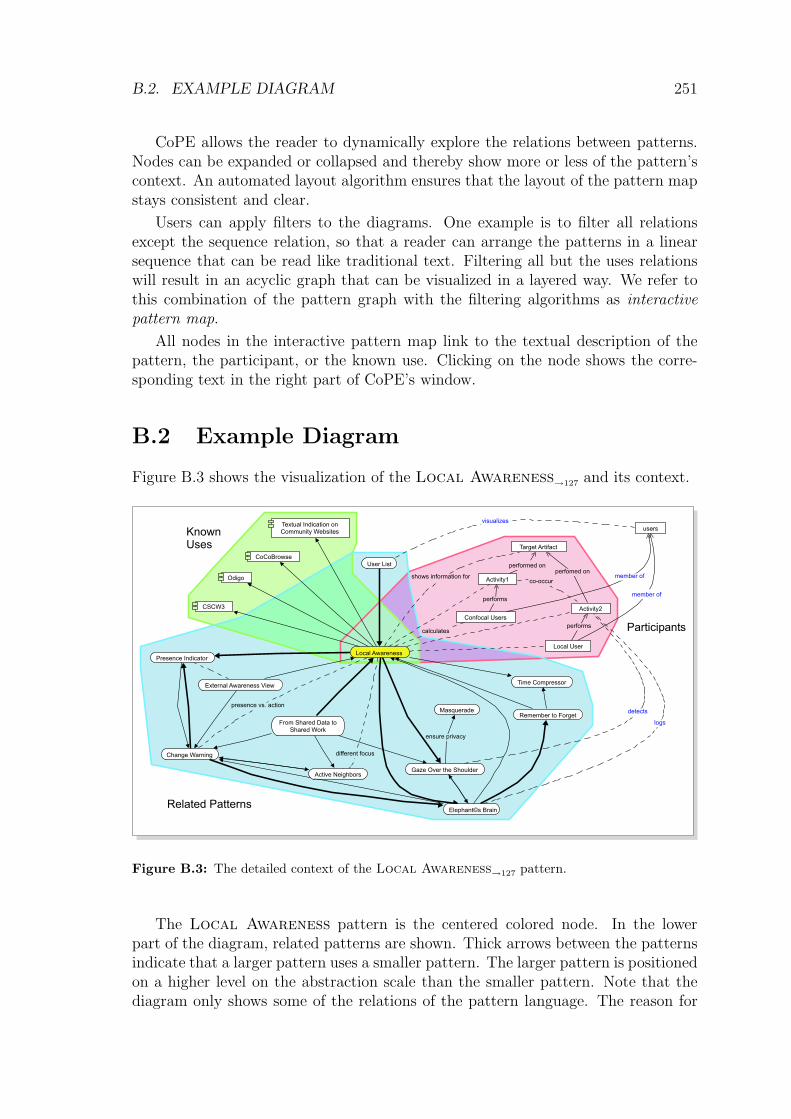
Appendix B
The Authoring and ViewingEnvironment CoPE
B.1 Linking Patterns in a Pattern Language
Patterns need to collude to create sequences of structure-preserving transformations.Alexander (1979) described this regard by comparing pattern languages with naturallanguages. As speakers connect single words to form literate sentences a user of apattern language can combine patterns in a pattern sequence in order to createwholeness.
But as learning a natural language is a difficult task the users also have tomanage the learning process of a pattern language. It is thus reasonable to look forsupportive means that help users in understanding relations in the pattern language.
Two obvious relations are already part of the pattern description. In the patterncontext patterns from a higher level of abstraction are named. The inverse relationis found in the related patterns section. such a relation from high-level patterns tothe patterns on the next lower level is in many cases bidirectional. But the exampleof the related pattern section already reveals a problem: Not all patterns named inthe related patterns section are patterns on a lower level of abstraction. They canalso be patterns on the same level that describe alternative solutions to the sameproblem.
We argue to support the user by illustrating a combined set of relations in apattern graph. The relations can be modeled as (labelled) edges between two patternnodes X and Y. We propose the following relations:
– X mentions Y in its context. This means that Y was applied before Y.
– X is related in its related patterns section to Y.
– X uses Y in its solution.
– X is a variant of Pattern Y.
247

248 APPENDIX B. THE COPE ENVIRONMENT
– X specializes Y. This relation is comparable to inheritance in object-orienteddevelopment where the subclass specializes its superclass. The specializedpattern still solves the problem of its ancestor but adds aspects that make thesolution more specific.
– X connects to Y as part of the sequence S. The label of the relation explainsthe step in the sequence that leads from X to Y.
Besides these relations between patterns we propose to add relations betweenpatterns and other artifacts:
– X and Y are members of the same family. A pattern family is a set of patternsthat are addressing a related design issue. Examples are patterns for providinggroup awareness or patterns for managing shared objects. A concrete exampleof a pattern family is the collection presented in chapter 5.
– X and Y involve a common participant P in the collaborations section of thepattern. In this case, X and Y are related to P. The label of the edge betweenthe pattern and the participant describes the role of the participant in thepattern.
– X and Y can be found in the same known use U. This is modeled using anedge between the pattern and U. The label explains how the pattern is usedin the known use.
All these relations have been part of the textual pattern description. But espe-cially the latter relations between patterns and other artifacts were not made explicit(because neither the participants nor the known uses were considered as first classobjects in current pattern structures). We argue that the relations should be mod-eled as explicit (typed) hyperlinks in the pattern description. With appropriate toolsupport (a hypertext environment) users can explore the different relations betweenpatterns and thereby gradually learn how the patterns form a pattern language.
We created the authoring and reading environment CoPE1 to support the usersand authors in reading, authoring and sharing the patterns. It is a collaborativeapplication that provides means for creating and linking pattern descriptions (cf. fig.B.1). It presents the pattern map (in the left part of fig. B.1) and the hypertextualrepresentation of the pattern (in the right part of fig. B.1). A pattern can be editedusing a WIKI syntax (Leuf and Cunningham, 2001).2 Especially, the author canadd links to other patterns that express the semantics of the relation.
The hypertext representation of the pattern is analyzed by the tool and a graphicrepresentation is created. The different relations between patterns can be expressedusing a graphic pattern diagram representation that is close to UML.
1CoPE is an acronym for Collaborative Pattern Editor.2A WIKI syntax is a collection of simple text markup commands that is parsed to generate
hypertexts.

B.1. LINKING PATTERNS IN A PATTERN LANGUAGE 249
Figure B.1: The reading and authoring environment CoPE.

250 APPENDIX B. THE COPE ENVIRONMENT
Participant Known UsePattern
Pattern A
B uses A,
A appears in B’s context
Pattern A
Pattern B
B relates to A
Pattern A
Pattern B
B extends A
Pattern B
Pattern A
Pattern B
A and B are variants
Pattern B
P participates in B
Participant P Known Use K
Pattern B
B is implemented in K
P knows Q
Participant P
Participant Q
Pattern
PatternFamily
Pattern is member
of the family
Participant P
Participant is of
type Class
Class
ClassPatternFamily
Diagram Elements
Relations
Figure B.2: Elements of pattern diagrams.
Patterns are represented as ovals.3 In most diagrams, the hyperlinks betweenpatterns are not detailed. This means that the relation between the patterns will beshown using a simple arrow without a label. CoPE allows the author to change thetype of an association in order to express specialization (extension) of a pattern, orvariants where two patterns solve the same problem differently.
If needed, pattern diagrams can be extended with information on known usesand participants. Known uses are shown as UML components (a rectangle with twolittle rectangles decorating the top-left corner). A solid line between the patternand the known use shows that the pattern was applied in the known use.
Participants are represented as rectangles (following the notation for objects inUML diagrams). They can be connected with directed associations. Each partici-pant can link to a class. This will be shown as a UML class symbol (with collapsedattributes and methods). It is not intended to include full UML object diagramsas part of the pattern diagram. So, the number of potential associations betweenobjects is limited to only one generic type.
Patterns can be grouped in families. A pattern family is visualized as an ovalwith two bottom lines. Families can also be shown using colored areas around thepatterns.
3Note that version 1.5 of the UML specification (Object Management Group, 2003) representspatterns as dashed ellipses. This notation is valid if the pattern is a secondary information in aclass or an interaction diagram. But in pattern diagrams the patterns should be in the main focus.One can assume that many patterns are shown in one diagram. Using ellipses (like in use casediagrams) would consume too much screen space and using dashed lines would make the elementssecondary compared to other elements like participants.

B.2. EXAMPLE DIAGRAM 251
CoPE allows the reader to dynamically explore the relations between patterns.Nodes can be expanded or collapsed and thereby show more or less of the pattern’scontext. An automated layout algorithm ensures that the layout of the pattern mapstays consistent and clear.
Users can apply filters to the diagrams. One example is to filter all relationsexcept the sequence relation, so that a reader can arrange the patterns in a linearsequence that can be read like traditional text. Filtering all but the uses relationswill result in an acyclic graph that can be visualized in a layered way. We refer tothis combination of the pattern graph with the filtering algorithms as interactivepattern map.
All nodes in the interactive pattern map link to the textual description of thepattern, the participant, or the known use. Clicking on the node shows the corre-sponding text in the right part of CoPE’s window.
B.2 Example Diagram
Figure B.3 shows the visualization of the Local Awareness→127
and its context.
shows information for
different focus
member of
ensure privacy
performed on
visualizes
perfomed on
performs
presence vs. action
performs
co-occur
logs
detects
calculates
member of
Odigo
User List
Activity1
Change Warning
External Awareness View
Gaze Over the Shoulder
Textual Indication onCommunity Websites
CoCoBrowse
Target Artifact
users
Remember to Forget
Confocal Users
Local User
CSCW3
Local Awareness
Activity2
Presence Indicator
Time Compressor
From Shared Data toShared Work
Masquerade
Active Neighbors
Elephant©s BrainRelated Patterns
KnownUses
Participants
Figure B.3: The detailed context of the Local Awareness→127 pattern.
The Local Awareness pattern is the centered colored node. In the lowerpart of the diagram, related patterns are shown. Thick arrows between the patternsindicate that a larger pattern uses a smaller pattern. The larger pattern is positionedon a higher level on the abstraction scale than the smaller pattern. Note that thediagram only shows some of the relations of the pattern language. The reason for

252 APPENDIX B. THE COPE ENVIRONMENT
this is that the inclusion of all relations would make the diagram hard to read in astatic version. In a dynamic version, the user can explore the relations by expandingor hiding related patterns.
The upper left part of the diagram shows known uses in which the pattern wasapplied. The upper right part of the diagram shows the different participants ofthe Local Awareness pattern and how these participants interact. Note thatother patterns also relate to these participants. By examining the use of the sameparticipant in different patterns, the user can gradually understand the differentdesign aspects for specific participants in groupware applications.

Appendix C
Tailoring Mechanisms in CURE
In order to provide the users with opportunities for tailoring the CURE environment,the environment has to provide tailoring access points. CURE provides tailoring attwo levels (Bourimi et al., 2003).
At the structural level, users can reshape the environment (the room structure) inorder to support different group structures and collaboration spaces. Users could forinstance create a room for supporting a virtual seminar that has several sub-rooms:
– one room for each subgroup in which they can prepare their presentations,
– a cafeteria in which the participants socialize,
– a literature room in which all groups collect and share their literature,
– a speaker’s room in which the participants can rehearse their talk, and
– a presentation room for giving and filing presentations.
Users can prepare full room structures and share them with other users. For a con-crete seminar, the users copy the template room structure and fill it with appropriate(seminar specific) content.
In a lower tailoring level, users can define how the pages in a room should look andbehave. They can define fields that have to appear on each page using a templatedescription language that is an extension of the WIKI syntax used to edit pagecontent. The template description language provides elements for defining inputfields and displaying entered values. The most important elements are:
wikiTextInput is used to define an input field. The template author provides anid and optionally the size of the field. Note that the template author caninvent new ids. This empowers him to describe any domain specific objectswith a template. The wikiTextInput fields can also be used to connect differenttemplates. Imagine that a tailorer wants to provide a room in which patternscan be collected. He defines a pattern template with the needed input fieldsfor describing a pattern in a PLML-like style. Then he decides that users
253

254 APPENDIX C
should be able to connect patterns with descriptions of known uses. Insteadof including the known uses on the pattern pages, the template author createsa second template (the knownUses template) and decides that pages createdfrom the known uses field of the pattern template should automatically linkto new instances of knownUses pages.
The element would look like this:
<wikiTextInput id="knownUses"template="knownUses"/>
renderedText is used to visualize the content of a field. It translates the plaintext entered by the user to a html representation. Imagine that a user hasprovided a field with the id scenario in his edit template. He can then usethe element
<renderedText id="scenario"/>
in his display template to show a formatted version of the text entered by theuser.
unrenderedText is comparable to the renderedText element with the differencethat no formatting is applied before displaying the content.
wikiSelectUser can be used to select a user from a list of users who can enter theroom. It can be used, e.g., on a page that describes user stories. The authorselects his name from the list of users in order to say that the story comesfrom his personal context.
wikiShowUser takes the input from a wikiSelectUser field and transforms it anInteractive User Info
→199.
wikiAppendText can be used in the display template in order to provide fieldsthat can be appended by the users. In the case of the virtual seminar, one couldthink of a positionStatement template that is used to collect the participants’positions regarding the seminar’s topic. In a later phase, the students are askedto comment each position. One way to support this process is to provide anappendable field in the display template of the positionStatement. When userssee the page, they can comment it and the comments will be appended in thefield specified in the wikiAppendText element.
The example in chapter 6.5 used the following templates:
Display Template
<pageToolBar />
<box>
<boxTitle>Details for the paper "<pageTitle />"</boxTitle>
<box>
<boxTitle>Cite as:</boxTitle>
<box style="border-width:0px; background-color:#ffffee;">
__<unrenderedText id="author" /> (<unrenderedText id="year" />).__
~~<pageTitle />.~~ In: <unrenderedText id="volume" />.
TAILORING MECHANISMS IN CURE 255
<unrenderedText id="place" />, <unrenderedText id="pages" />.
~~(Online at: <unrenderedText id="url" />)~~
</box>
</box>
<box>
<boxTitle>Summary</boxTitle>
!!Research Questions
<box style="border-width:0px; background-color:#ffffee;">
<renderedText id="research Questions" /></box>
!!Methods
<box style="border-width:0px; background-color:#ffffee;">
<renderedText id="research Methods" /></box>
!!Results
<box style="border-width:0px; background-color:#ffffee;">
<renderedText id="research Results" /></box>
</box>
!!!Comments by other students or teachers
<box style="border-width:0px; background-color:#ffeeee;">
<renderedText id="comment" /></box>
<wikiAppendText id="comment" lines="5" cols="90" rememberAuthor="yes" />
<div align="right"><editInformation /></div>
</box>
Edit Template
<box>
!!Bibliographic Data
|Author: | <wikiTextInput id="author" />|
|Title: | <wikiTextInput id="/pageTitle" />|
|In: | <wikiTextInput id="volume" />|
|Place: | <wikiTextInput id="place" />|
|Year: | <wikiTextInput id="year" />|
|Pages: | <wikiTextInput id="pages" />|
|URL: | <wikiTextInput id="url" />|
!!Summary
|Research Questions: | <wikiTextInput lines="8" id="research Questions" />|
|Research Methods: | <wikiTextInput lines="8" id="research Methods" />|
|Results: | <wikiTextInput lines="8" id="research Results" />|
<submitButton /><cancelButton />
</box>
In the above example, the tailorer provided fields for the paper’s bibliographicattributes (author, title, date, ...), a link to the paper’s source (the pdf file), and astudent summary containing addressed research questions, used methods and results.The student can fill these fields when pressing the edit button of a literature page(cf. fig. C.1).
In the display view (fig. C.2), the fields of the template are automatically ar-ranged. For instance, the bibliographic data is brought into the form required by
256 APPENDIX C
Figure C.1: Edit view of a literature summary.
diploma theses at the specific university department. In addition, the display tem-plate contains a field for commenting the page. Teachers as well as students can usethis field to add a public assessment.

TAILORING MECHANISMS IN CURE 257
Figure C.2: Display view of a literature summary.

258 APPENDIX C

Bibliography
Abrahamsson, P., Warsta, J., Siponen, M. T., and Ronkainen, J. (2003). Newdirections on agile methods: a comparative analysis. In ICSE ’03: Proceedingsof the 25th International Conference on Software Engineering , pp. 244–254.IEEE Computer Society.
Alexander, C. (1964). Notes on the Synthesis of Form. Cambridge, Mas-sachusetts: Harvard University Press, 7 (2002) edition.
Alexander, C. (1965). A city is not a tree. ARCHITECTURAL FORUM ,122:pp. 58–62.
Alexander, C. (1979). The timeless way of building . New York: Oxford Uni-versity Press.
Alexander, C. (2003a). The phenomenom of life, volume 1 of The nature oforder . Berkeley, California, USA: Center for Environmental Structure.
Alexander, C. (2003b). The process of creating life, volume 2 of The nature oforder . Berkeley, California, USA: Center for Environmental Structure.
Alexander, C., Ishikawa, S., and Silverstein, M. (1968). A pattern languagewhich generates multi-service centers. University of California, Berkeley: Cen-ter for environmental structure.
Alexander, C., Ishikawa, S., Silverstein, M., Jacobson, M., Fiksdahl-King, I.,and Angel, S. (1977). A pattern language. New York: Oxford University Press.
Alexander, C., Silverstein, M., Angel, S., Ishikawa, S., and Abrams, D. (1980).The Oregon Experiment . New York: Oxford University Press.
Ambler, S. W. (2005a). Agile modeling and the rational unified process (rup).�
http://www.agilemodeling.com/essays/agileModelingRUP.htm
Ambler, S. W. (2005b). Introduction to the enterprise unified process (eup).Technical report, Ronin International, Inc.�
http://www.enterpriseunifiedprocess.info/downloads/eupIntroduction.pdf
Ambler, S. W., Nalbone, J., and Vizdos, M. (2005). Enterprise Unified ProcessExtending the Rational Unified Process . Prentice Hall.
259

260 BIBLIOGRAPHY
AML (1977). Act No. 4 of 4 February 1977 relating to Worker Protection andWorking Environment . Norwegian Government.�
http://www.arbeidsplassen.no/legislation/en/amleng.pdf
Anderson, B. (1992). Towards an architecture handbook . New York, NY, USA:ACM Press.
Anderson, F. (2000). A collection of history patterns. In Harrison, N., Foote,B., and Rohnert, H. (Editors), Pattern Languages of Program Design 4 , pp.263–297. Reading, MA, USA: Addison-Wesley.
Appelt, W. and Mambrey, P. (1999). Experiences with the BSCW sharedworkspace system as the backbone of a virtual learning environment for stu-dents. In Proceedings of ED-MEDIA99 .
Autonomy (2002). Collaboration & expertise networks – cen. Aut cen 11.02,Autonomy Inc.�
http://www.autonomy.com/
Baker, F. T. (1972). Chief programmer team management of production pro-gramming. IBM Systems Journal , 11(1):pp. 56–73.�
http://www.research.ibm.com/journal/sj/111/ibmsj1101E.pdf
Bardram, J. E. (2000). Scenario-based design of cooperative systems re-designing an hospital information system in denmark. Group Decision andNegotiation, 9:pp. 237–250.�
http://www.daimi.au.dk/~bardram/docs/ScenarioBasedDesign_Bardram.pdf
Beck, K. (1999). eXtreme Programming Explained . Reading, MA, USA: Ad-dison Wesley.
Beck, K., Beedle, M., van Bennekum, A., Cockburn, A., Cunningham, W.,Fowler, M., Grenning, J., Highsmith, J., Hunt, A., Jeffries, R., Kern, J., Mar-ick, B., Martin, R. C., Mellor, S., Schwaber, K., Sutherland, J., and Thomas,D. (2001). Manifesto for agile software development.
Beck, K., Coplien, J. O., Crocker, R., Dominick, L., Meszaros, G., Paulish,F., and Vlissides, J. (1996). Industrial experience with design patterns. InProceedings of the 18th International Conference on Software Engineering ,pp. 103–114. Berlin, Germany: IEEE Computer Society Press.
Beck, K. and Fowler, M. (2001). Planning Extreme Programming . AddisonWesley Longman.
Bentley, R., Appelt, W., Busbach, U., Hinrichs, E., Kerr, D., Sikkel, K.,Trevor, J., and Woetzel, G. (1997a). Basic support for cooperative work on theworld-wide web. International Journal of Human-Computer Studies: Specialissue on Innovative Applications of the World-Wide Web.

BIBLIOGRAPHY 261
Bentley, R., Horstmann, T., and Trevor, J. (1997b). The world wide web asenabling technology for cscw: The case of bscw.
Bergin, J. (2002). Patterns for the doctoral student. PRELIMINARY– (Edi-tion 3).�
http://csis.pace.edu/~bergin/patterns/DoctoralPatterns.html
Beringer, J. (2004). Reducing expertise tension. Commun. ACM , 47(9):pp.39–40.
Bikson, T. K. and Eveland, J. D. (1996). Groupware implementation: rein-vention in the sociotechnical frame. In CSCW ’96: Proceedings of the 1996ACM conference on Computer supported cooperative work , pp. 428–437. NewYork, NY, USA: ACM Press.
Bjerknes, G. and Bratteteig, T. (1995). User participation and democracy: adiscussion of scandinavian research on systems development. Scand. J. Inf.Syst., 7(1):pp. 73–98.
Boehm, B. and Turner, R. (2004). Balancing Agility and Discipline – A Guidefor the Perplexed . Boston, MA: Addison Wesley.
Boehm, B. W. (1988). A spiral model of software development and enhance-ment. IEEE Computer , 21(5):pp. 61–72.
Booch, G. (1992). The booch method: Notation. Technical report, Rational,Inc., Santa Clara, CA.
Booch, G. (2001). Developing the future. Commun. ACM , 44(3):pp. 118–121.
Borchers, J. (2001). A Pattern Approach to Interaction Design. John Wileyand Sons Ltd.
Borchers, J. O. (2000a). Interaction design patterns: Twelve theses. InPosition Paper for the CHI Workshop “Pattern Languages for InteractionDesign: Building Momentum”.�
http://www.it.bton.ac.uk/staff/rng/CHI2K\_PLworkshop/PositionPapers/
Borch%ers.pdf
Borchers, J. O. (2000b). A pattern approach to interaction design. In Confer-ence proceedings on Designing interactive systems: processes, practices, meth-ods, and techniques , pp. 369–378. New York City, New York: ACM Press.
Bourimi, M., Haake, J., Landgraf, B., Schummer, T., and Haake, A. (2003).Two-level tailoring support for cscl. In Proceedings of CRIWG03 .
Bradshaw, S., Budzik, J., Fu, X., and Hammond, K. J. (2002). Clustering foropportunistic communication. In Proceedings of WWW 2002 . ACM Press.

262 BIBLIOGRAPHY
Buschmann, F., Meunier, R., Rohnert, H., Sommerlad, P., and Stal, M. (1996).A system of patterns, volume 1 of Pattern-Oriented Software Architecture.Chichester, West-Sussex, UK: John Wiley and Sons.
Carotenuto, L., Etienne, W., Fontaine, M., Friedman, J., Muller,M., Newberg, H., Simpson, M., Slusher, J., and Stevenson, K.(1999). Communityspace: Toward flexible support for voluntary knowl-edge communities. In online proceedings of “CHANGING PLACES -the workshop on workspace models for collaboration”, pp. available onlineat http://www.dcs.qmw.ac.uk/research/distrib/Mushroom/workshop/final–papers/lotus.pdf. London.
Carroll, J. M. (Editor) (1995). Scenario-based design: envisioning work andtechnology in system development . New York, NY, USA: John Wiley & Sons,Inc.
Cincom (2001). VisualWorks Application Developer’s guide. Cincinnati: Cin-com Systems, Inc.
CMMI Product Team (2002). Capability maturity model r© integration (cm-mism). Technical Report CMU/SEI-2002-TR-012, Carnegie Mellon University.�
http://www.sei.cmu.edu/pub/documents/02.reports/pdf/02tr012.pdf
Coad, P. (1992). Object-oriented patterns. Commun. ACM , 35(9):pp. 152–159.
Coad, P., Lefebvre, E., and De Luca, J. (1999). Java Modeling In Color WithUML: Enterprise Components and Process. Prentice Hall.
Cockburn, A. (2000). Writing Effective Use Cases. Boston: Addison-Wesley.
Cockburn, A. (2002). Agile Software Development . Boston, MA: AddisonWesley.
Cohen, D., Jacovi, M., Maarek, Y. S., and Soroka, V. (2000). Collectionawareness on the web via livemaps. In CSCW’2000 Workshop on Awarenessand the WWW . http://www2.mic.atr.co.jp/dept2/awareness/.
Cohen, D., Lindvall, M., and Costa, P. (2003). Agile software development.DACS State-of-the-Art-Report DACS-SOAR-11, The Data & Analysis Centerfor Software (DACS).�
http://fc-md.umd.edu/fcmd/papers/DACS-SOAR-AgileSoftwareDevelopment.pdf
Coldeway, J. (2003). Interaction patterns of agile development. InO’Callaghan, A., Eckstein, J., and Schwanninger, C. (Editors), Proceedingsof the Seventh European Conference on Pattern Languages of Programs (Eu-roPLoP’02), pp. 329–342. Irsee, Germany: UVK.

BIBLIOGRAPHY 263
Coplien, J. O. (2003). Not yet “drunk on god” – a sobering view of patternsprogress. The Cutter Edge, 16(9):pp. 5–9.�
http://www.cutter.com
Coplien, J. O. and Harrison, N. B. (2004 (to be published)). OrganizationalPatterns of Agile Software Development . Prentice Hall.�
http://easycomp.info.uni-karlsruhe.de/~jcoplien/HarrisonCoplien.pdf
Crabtree, A., Hemmings, T., and Rodden, T. (2002). Pattern-based supportfor interactive design in domestic settings. In Proceedings of the conference onDesigning interactive systems , pp. 265–276. ACM Press.
Cremers, A. B., Kahler, H., Pfeifer, A., Stiemerling, O., and Wulf, V. (1998).Politeam - kokonstrutive und evolutionare entwicklung einer groupware.Informatik-Spektrum, 21(4):pp. 194 – 202.�
http://www.helge-kahler.de/publications/CREMERS_KAHLER_PFEIFER_
STIEMERLIN%G_WULF_1998.PDF
Cullmann, M. (2004). Expertenfindung als Mittel der Benutzerfuhrung inCURE . Master’s thesis, FernUniversitat in Hagen.�
http://www.pi6.fernuni-hagen.de/publ/expertenfindung.pdf
Curtis, P. (1998). High Wired : On the Design, Use, and Theory of EducationalMoos , chapter Not Just a Game: How LambdaMOO Came to Exist and WhatIt Did to Get Back at Me, pp. 25–44. University of Michigan Press.
Dahlback, N., Jonsson, A., and Ahrenberg, L. (1993). Wizard of oz studies:why and how. In IUI ’93: Proceedings of the 1st international conference onIntelligent user interfaces, pp. 193–200. New York, NY, USA: ACM Press.
David, B., Delotte, O., Chalon, R., Tarpin-Bernard, F., and Saikali, K. (2003).Patterns in collaborative system design, development and use. In 2nd Work-shop on Software and Usability Cross-Pollination: The Role of Usability Pat-terns – Official workshop of IFIP working group 13.2 ”Methodologies for usercentred systems design”. Zurich, Switzerland.
Davis, A. M. (1997). Software Project Management , chapter Software LifeCycle Models, pp. 105–114. Los Alamitos, California: Institute of Electricaland Electronics Engineers Computer Society Press.
Dawkins, R. (1989). The Selfish Gene. Oxford University Press.
Dearden, A., Finlay, J., Allgar, E., and Barbara, M. (2002). Using patternlanguages in participatory design. In Binder, T., Gregory, J., and Wagner, I.(Editors), Proceedings of the Participatory Design Conference (PDC 2002),pp. 104–113. Palo Alto, CA: CPSR.�
http://www.lmu.ac.uk/ies/comp/research/isle/patterns/papers/PDCpaper.
264 BIBLIOGRAPHY
Deming, W. E. (1982). Out of the Crisis. MIT Press International.
Dewan, P. (2001). An integrated approach to designing and evaluating col-laborative applications and infrastructures. Computer Supported CooperativeWork , 10:pp. 75–111.
Dorfman, M. (1997). Requirements engineering. In Thayer, R. H. and Dorf-man, M. (Editors), Software Requirements Engineering , pp. 7–22. Los Alami-tos, CA, USA: IEEE Computer Society Press.
Dourish, P. (1997). Extending awareness beyond synchronous collaboration. InPosition paper for the ACM CHI’97 Workshop on Awareness in CollaborativeSystems . Atlanta, Georgia.
Dourish, P. and Bellotti, V. (1992). Awareness and coordination in sharedworkspaces. In Conference proceedings on Computer-supported cooperativework , pp. 107–114.
DSDM Consortium (1997). Dynamic systems development method, version 3.Technical report, DSDM Consortium, Ashford, UK.�
http://www.dsdm.org
Duyne, D. K. V., Landay, J., and Hong, J. I. (2002). The Design of Sites:Patterns, Principles, and Processes for Crafting a Customer-Centered WebExperience. Addison-Wesley Longman Publishing Co., Inc.
Eckstein, J. (1999). Workshop report on the pedagogical patterns project: Suc-cesses in teaching object technology. In Proceedings of OOPSLA’99 Educator’sSymposium. Denver.
Erickson, T. (2000). Lingua francas for design: sacred places and patternlanguages. In Proceedings of the conference on Designing interactive systems ,pp. 357–368. ACM Press.
Esfeld, M. (2003). Holismus und Individualismus in den Wissenschaften.,chapter Holismus und Atomismus in den Geistesund Naturwissenschaften.Eine Skizze, pp. 7–21. Lang.�
http://www2.unil.ch/philo/Pages/epistemologie/bio\_cv\_esfeld/pdf/2003\
_p%df/Bergs\_Curdts03.pdf
Fallman, D. (2003). Design-oriented human-computer interaction. In CHI’03: Proceedings of the SIGCHI conference on Human factors in computingsystems , pp. 225–232. New York, NY, USA: ACM Press.
Feldmann, B. and Schlageter, G. (2001). Five years virtual university – reviewand preview. In Proceedings of WebNet 2001 . Orlando, Florida.
Feldmann-Pempe, B., Schonwald, O., and Schlageter, G. (1999). Virtual uni-versity hagen: The internet communication environment. In Proceedings ofICCE’99 . Chiba.

BIBLIOGRAPHY 265
Fernandez, A., Haake, J. M., and Goldberg, A. (2002). Tailoring group work.In Haake, J. M. and Pino, J. A. (Editors), Proceedings of the CRIWG’2002– 8th International Workshop on Groupware, LNCS 2440, pp. 232–242. LaSerena, Chile: Springer-Verlag Berlin Heidelberg.
Fernandez, A., Holmer, T., Rubart, J., and Schummer, T. (2003). Three group-ware patterns from the activity awareness family. In Proceedings of the Sev-enth European Conference on Pattern Languages of Programs (EuroPLoP’02).Konstanz, Germany: UVK.
Fincher, S., Finlay, J., Greene, S., Jones, L., Matchen, P., Thomas, J., andMolina, P. J. (2003). Perspectives on hci patterns: concepts and tools. In CHI’03 extended abstracts on Human factors in computing systems , pp. 1044–1045.ACM Press.
Fincher, S. A. (2003). Chi 2003 workshop report: Perspectives on hci patterns:Concepts and tools (introducing plml). interfaces, (56):pp. 26–28.�
http://www.bcs-hci.org.uk/interfaces/interfaces56.pdf
Finlay, J., Allgar, E., Dearden, A., and Barbara, M. (2002). Patterns lan-guages in participatory design. In Faulkner, X., Finlay, J., and Detienne, F.(Editors), People and Computers XVII: Memorable yet Invisible, Proceedingsof HCI’2002 , pp. 159–174. Springer Verlag.�
http://www.lmu.ac.uk/ies/comp/research/isle/patterns/papers/hci.pdf
Fischer, G. and Giaccardi, E. (2004). End user development: Empoweringpeople to flexibly employ advanced information and communication technology.,chapter Meta-Design: A Framework for the Future End-User Development.Dordrecht, The Netherlands: Kluwer Academic Publishers. In press.
Fischer, G., Grudin, J., McCall, R., Ostwald, J., Redmiles, D., Reeves, B.,and Shipman, F. (2001). Seeding, evolutionary growth and reseeding: Theincremental development of collaborative design environments. In Olson, G.,Malone, T., and Smith, J. (Editors), Coordination Theory and CollaborationTechnology , pp. 447–472. Lawrence Erlbaum Associates.�
http://www.ics.uci.edu/~redmiles/publications/B002-FGMcC01.pdf
Fitzpatrick, G. A. (1998). The Locales Framework: Understanding and De-signing for Cooperative Work . Ph.D. thesis, Department of Computer Scienceand Electrical Engineering, The University of Queensland.�
http://www.cis.unisa.edu.au/~cisjrw/thesis.pdf
Floyd, C., Reisin, F.-M., and Schmidt, G. (1989). Steps to software devel-opment with users. In ESEC ’89: Proceedings of the 2nd European SoftwareEngineering Conference, pp. 48–64. Springer-Verlag.
Foner, L. N. (1996). A multi-agent referral system for matchmaking. InThe First International Conference on the Practical Applications of Intelli-

266 BIBLIOGRAPHY
gent Agents and Multi-Agent Technology . London, UK.�
http://foner.www.media.mit.edu/people/foner/Reports/PAAM-96/PAAM.pdf
Fowler, M. (1997). Analysis Patterns: Reusable Object Models . Reading, Ma,USA: Addison Wesley.
Fowler, M. (1999). Refactoring - Improving the Design of Existing Code. ISBN:0-201-485676-2. Addison-Wesley.
Fowler, M. (2000). UML Distilled, Second Edition - A Brief Guide to the Stan-dard Object Modeling Language. ISBN: 020165783X. Reading, MA: Addison-Wesley.
Fricke, A. and Volter, M. (2000). Seminars – a pedagogical pattern languageabout teaching seminars effectively. In Devos, M. and Rupping, A. (Editors),Proceedings of the Fifth European Conference on Pattern Languages of Pro-grams (EuroPLoP’2000), pp. 87–128. Konstanz, Germany: UVK.
Fuchs, L., Poltrock, S., and Wetzel, I. (2001). Teamspace: An environmentfor team articulation work and virtual meetings. In Proceedings of WBC ’01,Web Based Collaboration (DEXA 2001). Munich, Germany.
Gabriel, R. P. (1996). Patterns of Software – Tales from the Software Com-munity . New York: Oxford University Press.
Gamma, E. (2002). Software Pioneers, chapter Design Patterns – Ten YearsLater, pp. 688–700. Spiringer, Heidelberg.
Gamma, E., Helm, R., Johnson, R., and Vlissides, J. (1993). Design patterns:Abstraction and reuse of oject-oriented design. In Nierstrasz, O. (Editor),Proceedings of ECOOP’93 , volume 707 of LNCS , pp. 406–431. Kaiserslautern,Germany: Springer-Verlag.
Gamma, E., Helm, R., Johnson, R., and Vlissides, J. (1995). Design Patterns:Elements of Reusable Object-Oriented Software. Reading, MA: Addison-Wesley.
Garfinkel, H. (1967). Studies in ethnomethodology . Englewood Cliffs, NJ,USA: Prentice Hall.
Gil-White, F. J. (2005). Perspectives on Imitation: From Mirror Neuronsto Memes , chapter Common misunderstandings of memes (and genes). MITPress.�
http://www.psych.upenn.edu/~fjgil/Memes2.pdf
Girgensohn, A. and Lee, A. (2002). Making web sites be places for social in-teraction. In Proceedings of the 2002 ACM conference on Computer supportedcooperative work , pp. 136–145. ACM Press.

BIBLIOGRAPHY 267
Graham, I. (2002). A Pattern Language for Web Usability . 0201788888.Addison-Wesley.�
http://www.wupatterns.com/
Greenberg, S. and Roseman, M. (2003). Using a room metaphor to ease tran-sitions in groupware. In Ackermann, M., Pipek, V., and Wulf, V. (Editors),Sharing Expertise: Beyond Knowledge Management , pp. 203–256. Cambridge,MA, USA: MIT Press.
Gross, T. (1999). Supporting awareness and cooperation in digital informationenvironments. In Presented at Basic Research Symposium at the Conferenceon Human Factors in Computing Systems – CHI’99 . Pittsburgh, PA.�
http://orgwis.gmd.de/\~gross/publ/chi1999/gross\_chi1999brs.html
Grudin, J. (1994). Groupware and social dynamics: eight challenges for devel-opers. Communications of the ACM , 37(1):pp. 92–105.
Guernsey, L. (1996). College ”moos”foster creativity and collaboration amongusers. The Chronicle of Higher Education, p. A24.�
http://www.bvu.edu/ctown/CHE.html
Guerrero, L. and Fuller, D. (1999). Design patterns for collaborative systems.In Proceedings of the Fifth International Workshop on Groupware (CRIWG).
Gutwin, C. and Greenberg, S. (1996). Workspace awareness for groupware.In Proceedings of the CHI ’96 conference companion on Human factors incomputing systems: common ground , pp. 208–209. Vancouver, BC Canada.
Gutwin, C. and Greenberg, S. (1997). Workspace awareness. In Positionpaper for the ACM CHI’97 Workshop on Awareness in Collaborative Systems .Atlanta, Georgia.
Gutwin, C. and Roseman, M. (1996). A usabilitay study of workspace aware-ness widgets. In Proceedings of the CHI ’96 conference companion on Humanfactors in computing systems: common ground , pp. 214–215. Vancouver, BCCanada.
Haake, J., Schummer, T., Haake, A., Bourimi, M., and Landgraf, B. (2004a).Supporting flexible collaborative distance learning in the cure platform. InProceedings of HICSS-37 . IEEE Press.
Haake, J. M., Haake, A., Schummer, T., Bourimi, M., and Landgraf, B.(2004b). End-user controlled group formation and access rights managementin a shared workspace system. In CSCW’04: Proceedings of the 2004 ACMconference on Computer supported cooperative work , pp. 554–563. Chicago,Illinois, USA: ACM Press.
Haake, J. M. and Schummer, T. (2003). Some experiences with collaborativeexercises. In Proceedings of CSCL’03 . Bergen, Norway: Kluwer AcademicPublishers.

268 BIBLIOGRAPHY
Hafele, H. and Maier-Hafele, K. (2004). 101 eLearning Seminarmethoden.Managerseminare Verlag.
Harrison, N. B. (1999). The language of shepherding - a pattern language forshepherds and sheep. In Proceedings of PLoP 1999 .�
http://hillside.net/patterns/EuroPLoP2001/shepherding.doc
Hazzan, O. and Tomayko, J. (2003). The reflective practitioner perspective inextreme programming. In Extreme Programming and Agile Methods – XP/Ag-ile Universe 2003 , volume 2753 of Lecture Notes in Computer Science, pp.51–61.
Heidegger, M. (1927). Sein und Zeit . Tubingen: Niemeyer, 17 (1993) edition.
Helm, R. (1995). Patterns in practice. In OOPSLA ’95: Proceedings of thetenth annual conference on Object-oriented programming systems, languages,and applications , pp. 337–341. New York, NY, USA: ACM Press.
Herrmann, T., Hoffmann, M., Jahnke, I., Kienle, A., Kunau, G., Loser, K.-U.,and Menold, N. (2003a). Concepts for usable patterns of groupware applica-tions. In Proceedings of the 2003 international ACM SIGGROUP conferenceon Supporting group work , pp. 349–358. ACM Press.
Herrmann, T., Hoffmann, M., Loser, K.-U., and Moysich, K. (2000).Semistructured models are surprisingly useful. In Designing Cooperative Sys-tems. Proc. of Coop 2000., pp. 159–174. Sophia Antipolis, France.
Herrmann, T., Kienle, A., Kunau, G., and Schummer, T. (2003b). From goodpractices to patterns – mining socio-technical patterns from experience withgroupware.�
http://www.groupware-patterns.org/ECSCW2003
Highsmith, J. (2000). Adaptive Software Development: A Collaborative Ap-proach to Managing Complex Systems. Dorset House.
Hirschheim, R., Klein, H. K., and Lyytinen, K. (1995). Information SystemsDevelopment and Data Modeling – Conceptual and Philosophical Foundations .Cambridge University Press.
Holtzblatt, K. and Beyer, H. (1993). Making customer-centered design workfor teams. Commun. ACM , 36(10):pp. 92–103.
Hong, J. I. and Landay, J. A. (2001). Webquilt: A framework for capturingand visualizing the web experience. In Proceedings of WWW10 , pp. 717–724.Hong Kong, China.
Jaabari, Y. (2004). Realisierung einer synchronen kooperativen Program-mierumgebung auf Basis von CVS . Master’s thesis, University of Dortmund.

BIBLIOGRAPHY 269
Jacobson, I., Booch, G., and Rumbaugh, J. (1999). Unified Software Develop-ment Process . Addison-Wesley.
Jarke, M. (1999). Scenarios for modeling. Commun. ACM , 42(1):pp. 47–48.
Johnson-Lenz, P. and Johnson-Lenz, T. (1981). Consider the groupware: De-sign and group process impacts on communication in the electronic medium.In Hiltz, S. and Kerr, E. (Editors), Studies of Computer-Mediated Commu-nications Systems: A Synthesis of the Findings , volume 16. Newark, NewJersey: Computerized Conferencing and Communications Center, New JerseyInstitute of Technology.
Kahler, H., Mørch, A., Stiemerling, O., and Wulf, V. (2000). Tailorable sys-tems and cooperative work (introduction). Special Issue of Computer Sup-ported Cooperative Work , 9(1).
KBSt (2005). Das V-Modell-XT . Koordinierungs- und Beratungsstelle furInformationstechnik in der Bundesverwaltung (KBSt).�
http://www.kbst.bund.de/-,279/V-Modell.htm
Kerth, N. (1988). Workshop on specification and design. volume 23, pp. 9–16.New York, NY, USA: ACM Press.
Khaled, R., Barr, P., Noble, J., and Biddle, R. (2005). Metaphorscape – pat-terns for xp system metaphors. In Proceedings of EuroPLoP 2004 . Konstanz,Germany: UVK. In press.
Kovitz, B. L. (1999). Practical Software Requirements. Greenwich, CT, USA:Manning.
Krasner, G. E. and Pope, S. T. (1988). A cookbook for using the model-view-controller user interface paradigm in Smalltalk-80. Journal of Object-OrientedProgramming , 1(3):pp. 26–49.
Kramer, B. J. (2000). Fernuniversitat’s strategy to build a virtual university.Technical report, FernUniversitat in Hagen, Faculty of Electrical Engineeringand Information Engineering, Hagen, Germany.�
http://hera.csse.monash.edu.au/dsse/visits/2000-11-kraemer-paper.pdf
Kruchten, P. (2003). The Rational Unified Process: An Introduction. Addison-Wesley Professional, 3 edition.
Lakoff, G. (1993). Metaphor and Thought , chapter The Contemporary Theoryof Metaphor, pp. 202–251. Cambridge University Press.�
http://www.cf.ac.uk/encap/clcr/gordon/lakoff.pdf
Larman, C. and Basili, V. R. (2003). Iterative and incremental development:A brief history. IEEE Computer , (June):pp. 47–56.

270 BIBLIOGRAPHY
Lee, A., Girgensohn, A., and Schlueter, K. (1997). Nynex portholes: initialuser reactions and redesign implications. In Proceedings of the internationalACM SIGGROUP conference on Supporting group work : the integration chal-lenge, pp. 385–394. ACM Press.
Leuf, B. and Cunningham, W. (2001). The Wiki Way . Addison Wesley.
Lida, B., Hul, S., and Pilcher, K. (2003). Breadcrumb navigation: Furtherinvestigation of usage. Usability News, 5(1). Online publication of the Soft-ware Usability Research Laboratory, Department of Psychology, Wichita StateUniversity.�
http://www.usabilitynews.org
Lukosch, S. and Schummer, T. (2004a). Communicating design knowledgewith groupware technology patterns – the case of shared object manage-ment. In de Vreede, G.-J., Guerrero, L. A., and Raventos, G. M. (Editors),Groupware: Design, Implementation, and Use, 10th International Workshop,CRIWG 2004 , LNCS 3198, pp. 223–237. San Carlos, Costa Rica: Springer-Verlag Berlin Heidelberg.
Lukosch, S. and Schummer, T. (2004b). Patterns for managing shared ob-jects in groupware systems. In Proceedings of the 9th European Conference onPattern Languages and Programs. Irsee, Germany. Accepted paper.
Lukosch, S. and Schummer, T. (2005). Patterns for session management ingroupware systems. In Proceedings of the 10th European Conference on PatternLanguages and Programs . Irsee, Germany. Paper accepted for shepherding.
Malotaux, N. (2001). Evolutionary development methods. In Proceedings ofPROGRESS 2001 . Utrecht, the Netherlands: Technology Foundation (STW).�
http://www.stw.nl/progress2001/proc2001/malotaux.pdf
Manhart, P. (1999). A system architecture for the extension of structuredinformation spaces by coordinated cscw services. In GROUP ’99: Proceedingsof the international ACM SIGGROUP conference on Supporting group work ,pp. 346–355. New York, NY, USA: ACM Press.
Manns, M. L. and Rising, L. (2004). Fearless Change: Patterns for IntroducingNew Ideas. Addison-Wesley.
Mansfield, T., Ward, N., Rittenbruch, M., McEwan, G., Siqueira, J., andWilkinson, A. (2002). Sharing social recommendations: Towards a socialportal. In Proceedings of the Fourth International Conference on DistributedCommunities on the Web.�
http://pages.cpsc.ucalgary.ca/~mcewan/sharing-social-recommendations-dcw02.
Marathe, J. (1999). Creating community online. Technical report, DurlacherResearch Ltd.
BIBLIOGRAPHY 271
Martin, D., Rodden, T., Rouncefield, M., Sommerville, I., and Viller, S. (2001).Finding patterns in the fieldwork. In Proceedings of the 7th European Confer-ence on Computer-Supported Cooperative Work , pp. 39–58. Bonn, Germany:Kluwer.
Martin, D., Rouncefield, M., and Sommerville, I. (2002). Applying patterns ofcooperative interaction to work (re)design: e-government and planning. In CHI’02: Proceedings of the SIGCHI conference on Human factors in computingsystems , pp. 235–242. ACM Press.
McGrath, J. E. (1984). Groups: Interaction and Performance, chapter Meth-ods for the study of Groups, pp. 28–37. Prentice Hall, Englewood Cliffs, NewJersey.
Merriam-Webster (2000). Merriam-Webster’s Collegiate Dictionary . Merriam-Webster. Electronic edition.
Milne, M. A. (1971). Clustr: A program for structuring design problems. InDAC ’71: Proceedings of the 8th workshop on Design automation, pp. 242–249.ACM Press.
Mularz, D. E. (1995). Pattern-based integration architectures. In Coplien,J. O. and Schmidt, D. C. (Editors), Pattern Languages of Program Design 1 ,pp. 441–452. Reading, MA, USA: Addison-Wesley.
Muller, M. J. (2003). The Human-Computer Interaction Handbook: Funda-mentals, Evolving Technologies and Emerging Applications (Human Factorsand Ergonomics), chapter Participatory Design: The Third Space in HCI, p.chapter 54. Lawrence Erlbaum.
Muller, M. J. and Kuhn, S. (1993). Participatory design. Communications ofthe ACM , 36(6):pp. 24–28.
Muller, M. J., Wildman, D. M., and White, E. A. (1993). Taxonomy of pdpractices: A brief practicioner’s guide. Communications of the ACM , 36(6):pp.26–27.
Mumford, E. (2000). Socio-technical design: An unfulfilled promise or a futureopportunity. In Baskerville, R., Stage, J., and DeGross, J. I. (Editors), Organi-zational and Social Perspectives on Information Technology . Boston: KluwerAcademic Publishers.�
http://is.lse.ac.uk/Support/ifip\%5Fwg82/Aalborg/mumford.pdf
Naur, P. and Randell, B. (Editors) (1968). Software Engineering: Report of aconference sponsored by the NATO Science Committee. Garmisch, Germany,Brussels (1969): Scientific Affairs Division.�
http://homepages.cs.ncl.ac.uk/brian.randell/NATO/nato1968.PDF

272 BIBLIOGRAPHY
Nuseibeh, B. and Easterbrook, S. (2000). Requirements engineering: aroadmap. In ICSE ’00: Proceedings of the Conference on The Future of Soft-ware Engineering , pp. 35–46. ACM Press.
Object Management Group (2003). OMG Unified Modeling Language Specifi-cation. OMG.�
http://www.omg.org/docs/formal/03-03-01.pdf
Odigo (2001). Company homepage.�http://corp.odigo.com/
OTI (2003). Eclipse platform technical overview. Technical report, ObjectTechnology International, Inc.�
http://www.eclipse.org/whitepapers/eclipse-overview.pdf
Paetsch, F., Eberlein, A., and Maurer, F. (2003). Requirements engineeringand agile software development. In Twelfth International Workshop on En-abling Technologies: Infrastructure for Collaborative Enterprises, p. 308. Linz,Austria.
Pelrine, J., Knight, A., and Cho, A. (2001). Mastering ENVY/Developer .Cambridge University Press.
Pfister, H.-R., Schuckmann, C., Beck-Wilson, J., and Wessner, M. (1998).The metaphor of virtual rooms in the cooperative learning environment clear.In Streitz, N., Konomi, S., and Burkhardt, H. (Editors), Cooperative Build-ings - Integrating Information, Organization and Architecture. Proceedings ofCoBuild’98 , volume 1370 of LNCS , pp. 107–113. Heidelberg: Springer.
Pikrakis, A., Bitsikas, T., Sfakianakis, S., Roure, D. D., Hall, W., Reich, S.,and Hill, G. (1998). MEMOIR: Software agents for finding similar users bytrails. In Nwana, H. S. and Ndumu, D. T. (Editors), Proceedings of the 3rdInternational Conference on the Practical Applications of Agents and Multi-Agent Systems (PAAM-98), pp. 453–466. London, UK.�
http://www.mmrg.ecs.soton.ac.uk/publications/archive/pikrakis1998/html/
Preece, J. (2000). Online Communities . Chichester, UK: Wiley.
Price, D. (2000). Cvs - concurrent versions system v1.11.
Prince, M. and Schneider, A. (2004). Patterns for the end game. In Pro-ceedings of the 9th European Conference on Pattern Languages of Programs(EuroPLoP’04).
Prinz, W. (1999). Nessie: An awareness environment for cooperative settings.In Bodker, S., Kyng, M., and Schmidt, K. (Editors), Proceedings of the SixthEuropean Conference on Computer Supported Cooperative Work , pp. 391–410.Copenhagen, Denmark: Kluwer.

BIBLIOGRAPHY 273
Ramey, C. and Thompson, C. (2005). University of oregon campus plan.Technical report, University of Oregon Planning Office.�
http://darkwing.uoregon.edu/~uplan/LRCDPDraftPlan1web.pdf
Reeves, J. W. (1992). What is software design. C++ Journal , Fall.
Revell, M. (2004). Birmingham flashmob – a retrospective on 2003’s birming-ham flashmob, recorded a year on, with the event’s organiser. Radio Feature.�
http://www.understated.co.uk/radio/reports/brum_flashmob_story_270704.
mp3%
Rheingold, H. (1998). The Virtual Community: Homesteading on the Elec-tronic Frontier . MIT Press. Electronic edition.�
http://www.rheingold.com/vc/book/
Rittel, H. W. J. and Webber, M. M. (1973). Dilemmas in a general theory ofplanning. Policy Sciences , 4:pp. 155–169.
Rittenbruch, M., McEwan, G., Ward, N., Mansfield, T., and Bartenstein.,D. (2002). Extreme participation - moving extreme programming towardsparticipatory design. In Binder, T., Gregory, J., , and Wagner, I. (Editors),Participation and Design: Inquiring Into the Poltics, Contexts and Practicesof Collaborative Design Work – PDC 2002 Proceedings of the ParticipatoryDesign Conference. Malmo, Sweden.
Rodden, T. (1996). Populating the application: A model of awareness forcooperative applications. In Proceedings of the ACM 1996 conference on onComputer supported cooperative work , pp. 87–96.
Rohnert, H. (1995). The proxy design pattern revisited. In Vlissides, J. M.,Coplien, J. O., and Kerth, N. L. (Editors), Pattern Languages of ProgramDesign 2 , pp. 105–118. Reading, MA, USA: Addison-Wesley.
Rossi, G., Garrido, A., and Carvalho, S. (1995). Design patterns for object-oriented hypermedia applications. In Vlissides, J. M., Coplien, J. O., andKerth, N. L. (Editors), Pattern Languages of Program Design 2 , pp. 177–191.Reading, MA, USA: Addison-Wesley Addison-Wesley.
Rovai, A. (2002). Building sense of community at a distance. InternationalReview of Research in Open and Distance Learning , 3(1).�
http://www.irrodl.org/content/v3.1/rovai.pdf
Royce, W. (1970). Managing the development of large software system. InProceedings of IEEE WESCON .
Saridakis, T. (2003). A system of patterns for fault tolerance. In O’Callaghan,A., Eckstein, J., and Schwanninger, C. (Editors), Proceedings of the SeventhEuropean Conference on Pattern Languages of Programs (EuroPLoP’02), pp.535–582. Irsee, Germany: UVK.

274 BIBLIOGRAPHY
Schlichter, J., Koch, M., and Xu, C. (1998). Community Computing andSupport Systems: Social Interaction in Networked Communities , volume 1519of Lecture Notes in Computer Science, chapter Awareness - The Common LinkBetween Groupware and Community Support Systems
”p. 77. Springer.
Schmidt, D. (1996). Using design patterns to guide the development of reusableobject-oriented software. ACM Comput. Surv., 28(4es):p. 162.
Schon, D. A. (1983). The Reflective Practictioner: How Professionals Thinkin Action. New York: Basic Books.
Schuckmann, C., Schummer, J., and Schummer, T. (2000). Coast - einanwendungsframework fur synchrone groupware. In Proceedings of thenet.objectDays . Erfurt.�
http://net.objectdays.org/pdf/00/papers/ooss/schuemmer.pdf
Schuler, D. and Namioka, A. (1993). Participatory design: Principles andPractices . Hillsdale N.J.: Erlbaum.
Schummer, J., Schuckmann, C., Bibbo, L. M., and Zapico, J. J. (1999).Collaborative hypermedia design patterns in oohdm. In Proceedings of theHT99 Workshop on Hypermedia Development - Design Patterns in Hyperme-dia. Darmstadt.�
http://www.eng.uts.edu.au/~dbl/HypDev/ht99w/
Schummer, T. (2001a). GAMA-Mall – shopping in communities. In Fiege,L., Muhl, G., and Wilhelm, U. (Editors), Proceedings of the Second Interna-tional Workshop on Electronic Commerce (WELCOM’01), p. to be published.Heidelberg, Germany: Springer.
Schummer, T. (2001b). Lost and found in software space. In Proceedingsof the 34th Hawaii International Conference on System Sciences (HICSS-34),Collaboration Systems and Technology . Maui, HI: IEEE-Press.
Schummer, T. (2002). Enabling technologies for communities at web shops. InPlaice, J., Kropf, P. G., Schulthess, P., and Slonim, J. (Editors), Proceedingsof the 4th International Workshop on Distributed Communities on the Web(DCW2002), number 2468 in Lecture Notes in Computer Science, pp. 253 –265. Sydney, Australia: Springer.
Schummer, T. (2004a). GAMA – a pattern language for computer supporteddynamic collaboration. In Henney, K. and Schutz, D. (Editors), Proceedingsof the Eighth European Conference on Pattern Languages of Programs (Euro-PLoP’03). Konstanz, Germany: UVK.
Schummer, T. (2004b). Patterns for building communities in collaborativesystems. In Proceedings of the 9th European Conference on Pattern Languagesof Programs (EuroPLoP’04). Irsee, Germany: UVK, Konstanz, Germany.

BIBLIOGRAPHY 275
Schummer, T. (2004c). The public privacy – patterns for filtering personalinformation in collaborative systems. Pattern Language workshopped at theCHI 2004 workshop on Human-Computer-Human-Interaction Patterns, Fer-nUniversitat in Hagen.
Schummer, T., Borchers, J., Thomas, J. C., and Zdun, U. (2004). Human-computer-human interaction patterns: workshop on the human role in hcipatterns. In Extended abstracts of the 2004 conference on Human factors andcomputing systems , pp. 1721–1722. ACM Press.
Schummer, T., Fernandez, A., and Myller, M. (2005). Patterns for virtualplaces. In Proceedings of the 10th European Conference on Pattern Languagesand Programs. Irsee, Germany. Paper accepted for shepherding.
Schummer, T. and Haake, J. M. (2001). Supporting distributed software de-velopment by modes of collaboration. In Proceedings of ECSCW 2001 . Bonn.
Schummer, T. and Schummer, J. (2001). Support for distributed teams inextreme programming. In Succi, G. and Marchesi, M. (Editors), eXtremeProgramming Examined . Addison Wesley.
Schummer, T., Schummer, J., and Schuckmann, C. (2001). Coast - an opensource framework to build synchronous groupware with smalltalk. Technicalreport, OpenCoast Development Group.�
http://www.opencoast.org/documentation/CoastSTBook.pdf
Schummer, T. and Slagter, R. (2004). The oregon software development pro-cess. In Proceedings of XP2004 .
Schummer, T. and Zdun, U. (2004). Europlop 2004 focus group on human-computer-human interaction patterns. In Proceedings of the 9th EuropeanConference on Pattern Languages of Programs (EuroPLoP’04).
Schwaber, K. (2004). Agile Project Management with Scrum. Microsoft Press.
Shardanand, U. and Maes, P. (1995). Social information filtering: algorithmsfor automating “word of mouth”. In Proceedings of the SIGCHI conferenceon Human factors in computing systems, pp. 210–217. ACM Press/Addison-Wesley Publishing Co.
Slagter, R., Biemans, M., and Ter Hofte, G. H. (2001). Evolution in use ofgroupware: Facilitating tailoring to the extreme. In Proceedings of the CRIWGSeventh international Workshop on Groupware, pp. 68–73. Darmstadt: IEEEComputer Society Press.
Smuts, J. C. (1936). Holism and Evolution. London, UK: MacMillan and Co.,Ltd., 3 edition.

276 BIBLIOGRAPHY
Sohlenkamp, M. and Chwelos, G. (1994). Integrating communication, coop-eration, and awareness: the diva virtual office environment. In CSCW ’94:Proceedings of the 1994 ACM conference on Computer supported cooperativework , pp. 331–343. ACM Press.
Sohlenkamp, M., Prinz, W., and Fuchs, L. (2000). Poliawac – design andevaluation of an awareness enhanced groupware client. AI and Society – SpecialIssue on CSCW , 14:pp. 31–47.
Sørensen, K. E. (2002). Session patterns. In O’Callaghan, A., Eckstein, J., andSchwanninger, C. (Editors), Proceedings of the Seventh European Conferenceon Pattern Languages of Programs (EuroPLoP’02), pp. 301–321. Konstanz,Germany: UVK.
Stahl, G. (1993). Interpretation in Design: The Problem of Tacit and ExplicitUnderstanding in Computer Support of Cooperative Design. Ph.D. thesis,University of Colorado.�
http://www.cis.drexel.edu/faculty/gerry/publications/dissertations/
computer/dissertation.pdf
Summers, R. (1999). Official Microsoft NetMeeting Book . Redmond, WA,USA: Microsoft Press International.
Sun Microsystems (1989). NFS: Network File System Protocol specification.RFC 1094 (Informational).�
http://www.ietf.org/rfc/rfc1094.txt
Sutcliffe, A. and Mehandjiev, N. (2004). End-user development: Introduction.Communications of the ACM , 47(9):pp. 31–32.
Takeuchi, H. and Nonaka, I. (1986). The new new product development game.Harvard Business Review , pp. 137–146.
Teege, G. (2000). Users as composers: Parts and features as a basis for tai-lorability in cscw systems. Computer Supported Cooperative Work (CSCW),9:pp. 101–122.
Ter Hofte, G. H., Otte, R., and van der Gaast, S. (1997). Supporting tele-pointing in the mesh groupware platform: Design issues.
Thomas, J., Danis, C., Greene, S., and Schummer, T. (2002). Workshop onsocio-technical pattern languages.�
http://www.groupware-patterns.org/cscw2002
Tuckman, B. and Jenson, M. (1977). Stages of small group development re-visited. Group and Organisational Studies, pp. 419–427.
Underwood, G. M., Maglio, P. P., and Barrett, R. (1998). User centered pushfor timely information delivery. In Proceedings of the Seventh International

BIBLIOGRAPHY 277
World Wide Web Conference (WWW7). Brisbane, Australia.�
http://www7.scu.edu.au/programme/fullpapers/1894/com1894.htm
University of Oregon Planning Office (2005). Frequently Asked Questions aboutthe University’s use of the Pattern Language.�
http://darkwing.uoregon.edu/~uplan/FAQPatternLanquage.html
van Welie, M. (2005). Web design patterns.�
http://www.welie.com/
van Welie, M. and Klaassen, B. (2004). Evaluating museum websites usingdesign patterns. Technical report IR-IMSE-001, Vrije Universiteit Amsterdam.�
http://www.welie.com/articles/IR-IMSE-001-museum-sites.pdf
Wenger, E. (1998). Communities of Practice: Learning, Meaning, and Iden-tity . Cambridge: Cambridge University Press.
Wesson, J. and Cowley, L. (2003). Designing with patterns: Possibilities andpitfalls. In 2nd Workshop on Software and Usability Cross-Pollination: TheRole of Usability Patterns – Official workshop of IFIP working group 13.2”Methodologies for user centred systems design”. Zurich, Switzerland.
Wood, L. E. (1997). Semi-structured interviewing for user-centered design.interactions, 4(2):pp. 48–61.
Wulf, V., Krings, M., Stiemerling, O., Iacucci, G., Fuchs-Fronhofen, P., Hin-richs, J., Maidhof, M., Nett, B., and Peters, R. (1999). Improving inter-organizational processes with integrated organization and technology develop-ment. Journal of Universal Computer Science, 5(6):pp. 339 – 365.
Wulf, V. and Rohde, M. (1995). Towards an integrated organization and tech-nology development. In DIS ’95: Proceedings of the conference on Designinginteractive systems, pp. 55–64. ACM Press.

Index
Abstraction, 7Active Neighbors, 126, 130, 135, 212,
216, 225, 241Activity, 114, 123, 128, 151Activity Counter, 216, 225Activity flower, 190Activity Log, 151Activity Status Bar, 225Ad-hoc customer, 81Adaptive Software Development, 50Adhoc Meeting, 126Agile software development, 49Alexander, 11, 17Application Sharing, 226Are You Alive, 144Artifact, 7, 114, 128Ask the author, 226Attention Screen, 161, 195, 216Authoritative instance, 176, 226Awareness Proxy, 212, 226
Backlog, 56, 179in OSDP, 99
Believe in Your Group, 216, 227Bell, 194, 216, 227Big Jolt, 167Birds of a Feather, 176, 199, 210,
216, 236Bottom-up development, 41Breadcrumbs, 68Break, 10, 15, 101
in OSDP, 97Breakdown, see breakBSCW, 155, 160Buddy List, 98, 144, 216, 227
Center, 26, 28
Centralized Objects, 176, 213, 216,228
Change Log, 156Change Warning, 123, 133, 134, 140,
154, 161, 177, 188, 199, 213, 216,228, 231
ChiPlace, 166CLUSTR, 12CMM, 50COAST, 142CoCoBrowse, 132Collaboration scenarios, 82Collaborative Filtering, 228Collaborative Learning, 175Collaborative Session, 126, 141,
144, 216, 228Collaborative Web research, 211Color-Coded Distances, 140, 228,
243Command, 156Community, 1
of circumstances, 2of interest, 2of practice, 2of purpose, 2
Conceptual iterations, 95, 175Confocal user, 129, 137, 187Context, 7, 10, 26Contextual Awareness, 127Control Your Privacy, 210, 229Coordination, 21Crystal Methods, 50CSCL patterns, 206CSCW3, 132CURE, 174
Expert finder, 210
278

INDEX 279
CVS, 124, 129, 154
Daily Report, 119, 158, 188Decomposition, 17, 41, 78, 98
Semilattice, 12, 13Tree, 12
Democracy, 24Design
Conservative account, 8Pragmatic account, 8Romantic account, 8
Design customer, 81Detect A Conflicting Change,
216, 227, 229Development iterations, 98, 179Distinct Awareness Info, 139, 140,
212, 229Document Awareness, 127Domain-language, 64Don’t Disturb, 216, 229Don’t Trust Your Friends, 216,
230Door, 183, 192, 193, 216Dynamic Systems Development Method,
50
Eclipse, 212Edition, 156Elephant’s Brain, 119, 130, 146–148,
150, 159, 161, 169, 187, 188, 212,213, 216, 227, 231, 232, 238
Emoticon, 230End-user development, 63, 105End-user involvement, 24Enterprize Unified Process, 47Envy, 124Ethnographic methods, 61Ethnography, 85, 105Ethnomethodology, 19EuroPLoP, 214Evaluation method, 171Evaluation user
in OSDP, 101Evolutionary growth, 84Expert assessment, 174Expertise tension, 53
External Awareness View, 188,213, 231
eXtreme Programming, 51, 105for Groupware development, 81
Feature-Driven Development, 58Field experiment, 173Field study, 173Find the Guru, 216, 231Fitness, 11Flashmob, 1Floor Control, 177, 178, 231Fly on the wall, 215Forces, 11, 16, 101
Field of, 26From Shared Data to Shared
Work, 118, 120, 127, 129, 176,187, 212, 213
Fundamental properties, 27Boundaries, 28, 28, 192, 193, 195,
196, 199–201Contrast, 28, 29, 192–194Deep interlock and ambiguity,
28, 29, 194, 195, 198, 200Gradients, 28, 29, 193, 195, 200Levels of scale, 27, 28, 192, 193,
196Local Symmetries, 196Not-separateness, 28, 29, 193,
195, 198–200Simplicity and inner calm, 28,
29Strong centers, 28, 28, 193, 197,
199
GAMA Mall, 126, 139, 148Gang of Four (GoF), 66Gardener, 81
in OSDP, 100, 180Gaze Over the Shoulder, 119, 123,
126, 129, 130, 133, 145, 154, 155,169, 187, 188, 210, 212, 213, 216,226, 245
Group Award, 216, 232Group awareness, 114Group formation, 113, 118, 120, 197

280 INDEX
Groupware, 3Guess What I Need, 216, 232
Hall of Fame, 166–168, 210, 216, 232HCHI, 3Heidegger, 10Hello Hello, 119, 163, 169, 176, 191,
205, 206, 210, 216Holism, 26
I Am Alive, 144I2I, 126Immutable Versions, 233In-Place Awareness View, 135, 212,
233, 237Interaction, 115Interactive User Info, 140, 199, 254Interviews, 62Introduction Session, 168Invitation, 216, 233Iterative development, 17Iterative processes
Piecemeal growth, 22Iterative software development, 45
Knowing-in-action, 15
Laboratory experiment, 173Letter of Recommendation, 176,
177, 210, 212, 216, 228, 233Life, 12Life Indicator, 190, 204Lights off, 177, 216, 234Lingua Franca for design, 68Listener, 146Literature Pool, 208Local Awareness, 119, 122, 123, 126,
127, 135, 144, 146, 156, 187, 212,213, 216, 225, 231, 232, 238, 242,251
Lock and Key, 193, 194, 216Locomotion, 216, 234Login, 177, 181, 192, 193, 201Lovely Bags, 216, 235
Mailing list, 160Map, 184, 216
Marker, 235Masquerade, 130, 148, 165, 167, 196,
216Mediated Updates, 213, 216, 236Meme, 30Mentor, 167, 236Metaphor, 53Misfit, 11Mode of collaboration, 120Model-View-Controller, 156Moderator, 177, 236More than 1000 Words, 236MSN Messenger, 142
NATO conference, 40Navigation Observer, 149NESSIE, 148, 154
Odigo, 132Opposites Attract, 176, 236Oregon experiment, 21Organic order, 22OSDP, 95, 171
Conceptual iterations, 95, 175Development iterations, 98, 179Tailoring iterations, 101, 206
OTD, 82, 106
Participation, 21in XP, 53informed participation, 85Inter-organizational level, 25Social or working life level, 25Work situation level, 25Workplace or organizational level, 25
Participatory design, 21, 24, 60, 105Pattern scout, 101, 209Patterns
Abstrction scale, 112Alexandrian form, 18Analysis patterns, 68Application, 22, 73as Memes, 30Behavioral, 21CSCL, 89, 206Ethnography, 85

INDEX 281
Evaluation, 23Evolution, 23Generic centers, 30Groupware patterns, 106HCI patterns, 68, 106Level of scale, 19Low-level, 89Map, 17Mathematical description, 17Means for communication, 22Morphological law, 17Novelty, 70Participatory design, 75Pedagogical patterns, 206Socio-technical, 87, 106Software development, 65Sructure preserving transformation,
30Usability engineering life cycle, 74
Pay Back, 210, 216, 236PDSA, see Plan-Do-Study-ActPersonal Annotation, 237Personalized Attributes, 237Plan-Do-Study-Act, 16Planning, 16Planning game, 53, 181
in OSDP, 98Platform 2000, 174PLML, 71, 106PLoP conference series, 89PoliAwaC, 139PoliTeam, 139Presence Indicator, 119, 126, 133,
135, 154, 188, 210, 212, 216, 231Privacy, 193Prototyping, 62
Low-fidelity, 98Proxy, 148Proxy Object, 147, 155, 213, 237Proxy-Logger, 148Publisher-Subscriber, 134, 144
Quality without a name, 27
Radar View, 136, 238Rational Unified Process, 45, 106
Read, Read, Read, 206, 206Ready-to-hand, 10Reciprocity, 110, 111, 148, 196, 216,
229, 235, 238Refactoring, 52, 99Reflection, 16, 55
Diagnosis, 22Reflection-in-action, 16
Rehabilitation, 238Remember to Forget, 212, 238Remote Selection, 216, 239Remote Subscription, 239Remote Viewport, 216, 239Replicate for Freedom, 216, 239Replicate for Speed, 216, 239Requirements
Education, see R10End-User Development, see R13End-User Involvement, see R9Explicit Consequences, see R11Explicit Forces, see R8Field of Forces, see R7Integration, see R12Iterative Design, see R5One Problem at a Time, see R6Process Awareness, see R4Quality Review, see R15R11, 82, 90, 91, 104, 173, 179, 204,
209R14, 85, 90, 91, 104, 178, 204, 209,
220R10, 48, 55, 58, 63, 81, 84, 90, 91,
104, 173, 179, 204, 209, 213, 220R9, 39, 42–44, 48, 53, 58, 81, 84, 90,
91, 104, 179, 204, 220R13, 39, 48, 55, 63, 84, 90, 91, 104,
178, 204, 209R8, 82, 84, 90, 91, 104, 179, 204, 209R7, 82, 84, 90, 91, 104, 179, 204, 209,
213R12, 63, 84, 104, 179, 204, 213R5, 35, 39, 41–44, 48, 84, 103, 179,
204, 220R6, 48, 55, 59, 84, 90, 91, 103, 179,
204, 213

282 INDEX
R4, 42, 48, 54, 80, 81, 84, 103, 178,203, 209, 220
R3, 35, 42, 43, 48, 51, 54, 63, 80, 84,85, 90, 91, 103, 178, 203, 209, 220
R15, 85, 90, 91, 104, 178, 204R2, 52, 58, 84, 90, 91, 103, 178, 203R1, 34, 84, 103, 178, 203Reflection, see R3Sharing of Best Practices, see R14Structure-Preserving Transforma-
tions, see R2Wholeness, see R1
Requirements engineering, 8Role, 177, 240Room, 123, 144, 182, 192, 194, 201, 216,
231Room directory, 185Room map, 185Rugby approach, 32
Scenario interest group (SIG), 97Scenario-based design, 61SCOPE, 212Scrum, 55, 105Scrum Master, 56Semantic Distance, 212, 225, 228,
240, 240Semantic Net, 212, 216, 231, 240, 240,
241SER, 84, 106Session Timeout, 144Shared Annotation, 176, 177, 241Shared Folder, 176, 177, 182Shared Repository, 157Shepherd, 214Show the Expert, 210, 241SIG, 175Situatedness, 10, 28, 31, 113Spatial Domain Model, 241, 243Spiral development, 45STEPS, 64, 106Stories
in OSDP, 97Strong Center, 199Structure preserving transformation, 29Swarm and Collect, 212, 241
Tacit knowledge, 10Tailoring, 63, 101
Collaborative tailoring, 82Tailoring iterations, 101, 206Talk first, 123, 126, 199, 231, 233, 242Telecursor, 216, 242Tell Me a Story, 242Test-first, 51Testing
Diagnosis and repair, 22Theoretical evaluation, 174Threaded Discussions, 177, 242Time boxing, 54Time Compressor, 132, 133, 212, 238,
242Timeout, 225, 243Top-down development, 41Trade unions, 24Travel Together, 177, 216, 243TUKAN, 125, 139, 155
Unit of Work, 225, 243Update Your Friends, 216, 240, 243User Gallery, 110, 111, 144, 166, 168,
191, 197, 216User List, 119, 134, 141, 177, 187, 188,
191, 216User story, 99User-Centered Push (UCP), 148User-evaluation customer, 81
V-Model-XT, 44Virtual Me, 142, 144, 176, 177, 187,
197, 205, 206, 244virtual project backlog, 180Virtual Seminar, 175Virtual seminar, 176Visa, 200, 216VisualWorks Snalltalk, 154Vote, 238, 244
Waterfall method, 41for Groupware development, 78
Welcome area, 164WELL, 1Who am I, 142, 191

INDEX 283
Who’s Listening, 210, 216, 245Who’s that Girl, 147, 191, 245, 245Wholeness, 26, 201
Mathematical definition, 27Wicked problem, 14, 54Writer’s workshop, 89, 215
You Are Here, 245