Embed Size (px)
Citation preview

Research Article Open Access
Srivastva et al., J Appl Mech Eng 2016, 5:3 DOI: 10.4172/2168-9873.1000209
Research Article Open Access
Journal of Applied Mechanical EngineeringJo
urna
l of A
pplied Mechanical Engineering
ISSN: 2168-9873
Volume 5 • Issue 3 • 1000209J Appl Mech EngISSN:2168-9873 JAME, an open access journal
*Corresponding author: Srivastva HK, Associate Professor, Department ofMechanical Engineering, Naraina Group of Institutions, Kanpur 208020, India, Tel:9554180274; E-mail: [email protected]
Received March 01, 2016; Accepted March 29, 2016; Published April 03, 2016
Citation: Srivastva HK, Chauhan AS, Raza A, Kushwaha M, Bhardwaj PK (2016) Comparative Study of Different with al- sic for Engine Valve Guide by using FEM. J Appl Mech Eng 5: 209. doi:10.4172/2168-9873.1000209
Copyright: © 2016 Srivastva HK, et al. This is an open-access article distributed under the terms of the Creative Commons Attribution License, which permits unrestricted use, distribution, and reproduction in any medium, provided the original author and source are credited.
Comparative Study of Different with al- sic for Engine Valve Guide by using FEMSrivastva HK1*, Chauhan AS2, Raza A3, Kushwaha M3 and Bhardwaj PK3
1Department of Mechanical Engineering, Naraina Group of Institutions, Kanpur 208020, India2Department of Mechanical Engineering, Maharana Pratap Engineering College, Kanpur 209217, India3Department of Mechanical Engineering, Naraina Group of Institutions, Kanpur 208020, India
Abstract
In this Work an effort has been designed to raise the reliability of engine using Al-Sic composites with other alternatively materials for the engine valve guides. Aluminum matrix composites have found the most suitable inside automotive, aerospace and aircraft industries and contain the greatest promise for future year’s growth. The finite element analysis of the Al-Sic composite with Titanium alloy (Ti-834), Copper Nickel Silicon alloys (CuNi3Si), and aluminum bronze alloy as an alternative material for engine valve guide was done using Ansys 13.0 software. The stress analysis of engine valve guide under the different pressure and temperature is considered, the pressure is taken as from 10 MPa to 100 MPa with Different temperatures varying from 600 °C to 650 °C. The temperature, principal stress and principal strain distribution on the entire surface area of the engine valve guide were obtained. The stresses were observed to be well below the permitted stress for all the materials but the Al-Sic composites found the most suitable one. Valve guide is modeled in pro-engineer software and analysis is carried out in Ansys 13.0. The deformations and stresses induced due to structural and thermal loading is illustrated and discussed.
Keywords: Engine valve; Materials
IntroductionIn reaction to increasing worldwide competition and developing
concern for environment the auto manufacturers have already been encouraged to meet up the conflicting demands of increased power and performance, lower fuel consumption, lower pollution emission and reduced vibration and noise. To be able to fulfill these newer and emerging needs the Automobile industry has acknowledged the necessity for materials substitution. Metal matrix composites are providing outstanding properties in a true number of automotive components such as for example piston, cylinder liner, engine valves, brake discs, brake drums, clutch discs, linking rods etc. Several function has been documented on the substitution of presently utilized materials by the aluminum matrix composites for various automotive parts viz. piston, cylinder liner, engine valves, valve seat inserts etc. Al-Sic composite engine valve guides have already been fabricated through powder metallurgy and casting processes. The radial crushing strength, hardness, and wear resistance of the Al-SiC cast and composite iron engine valve guides were measured and compared. Al-SiC composites with 5 to 30 wt.% of SiC were discovered to have increased Rockwell hardness and radial crushing strength compared to the cast iron engine valve guides. Al-SiC composite engine valve guides with 20 and 30 wt. % of SiC were discovered to possess higher wear level of resistance compared to the cast iron engine valve guides. Existing work incorporates the finite element strategy to include the prospects of Al-SiC composites just as one alternative materials for the engine valve guides. The finite element Analysis of the engine valve guides was done making use of Ansys 13.0 software program. Temperature, displacement and pressure boundary conditions were used and the temperature, stress and stress distribution on the entire surface area of the engine valve guides was obtained. Aluminum alloys have discovered greater adoption while potential matrix materials in comparison to some other alloys. In 2000, Katsunao Chikahata and Koichiro Hayashi (Publication numberUS6012703 A) [1] presented valve guide and process for manufacturing, they say that valve guide which is manufactured by a sintered alloy and used for an engine, and more particularly, to a valve guide which has high wear
resistance and can prevent appearance of scuffing on a surface of a valve stem associated with the valve guide. In 2009, Suhael Ahmed [2] presented the Development and Characterization ofAl7075 BasedHybrid Composites. Aluminum based Metal matrix compositeshave been emerged as an important class of materials for structural,wear, thermal, transportation and electrical applications. Srinivasa R.Bakshi, Di Wang, Timothy Price, ArvindAgarwal in 2009,[3] presentedMicrostructure and Wear properties of Aluminum/Aluminum–Silicon Composite coatings prepared by cold spraying. Manoj Singla, D.Deepak Dwivedi, Lakhvir Singh, Vikas Chawla in 2009, [4] developed a conventional low cost method of producing MMCs and to obtainhomogenous dispersion of ceramic material. In 2011, Dunia AbdulSaheb [5] presented Aluminum silicon carbide and aluminum graphiteParticulate composites. Ramanpreet Singh, Er. Rahul Singla in 2012[6] presented Tribological Characterization of Aluminium-SiliconCarbide Composite Prepared by mechanical alloying aluminum metalcomposites is combinations of materials in such a way that the resulting materials have certain design properties on improved quality.
Material and PropertiesAl SIC composites
Shown in Tables 1-4
Problem Specification
Issue of sustainability, stability, durability and reliability of present
Page 2 of 6
Citation: Srivastva HK, Chauhan AS, Raza A, Kushwaha M, Bhardwaj PK (2016) Comparative Study of Different with al- sic for Engine Valve Guide by using FEM. J Appl Mech Eng 5: 209. doi:10.4172/2168-9873.1000209
Volume 5 • Issue 3 • 1000209J Appl Mech EngISSN:2168-9873 JAME, an open access journal
material for engine guide valve at high temperature about 600°C to 1000°C under very high pressure about 10 mpa-100 mpa back ground of the problem.
At the moment the engine valve guides are made of iron-based materials, which result in a true amount of problems within an automotive engine-
• During cold start condition the viscosity of oil is high and also sufficient lubricant is not available therefore high wear of the valve stem / valve guide takes place. In the adverse conditions the valve may jam in the guide.
• During running condition of the engine the temperature of the valve stem and valve guide increases to about 500°C. Therefore at high temperature the clearance between valves stem and valve guide decreases due to thermal expansion, which results in high wear of the valve stem and the guide.
• The superimposed rocking motion in addition to the sliding of the engine valve causes high wear at the ends of the valve guide called “bell-mouthing”, generally more pronounced in the rocker arm actuation mechanism.
These problems call for a high wear resistant material with low coefficient of thermal expansion and engine valve guides based on the Al-SiC composites are expected to provide a better solution.
Temperature DistributionTo understand the problem of wear and decreasing the clearance
the clearance due to temperature change at various load condition,
firstly have to analyze the temperature distribution in the valve and valve guide.
Typically we take example of exhaust valve temperature distribution in spark ignition engine of V-8 car with full throttle (3500 r/min). During expansion stoke the temperature of the burnt gases is about 600-800°C. These hot burnt gases get impact with head of poppet valve and head of poppet valve conduct the heat through various portion of poppet valve.
• Small part about 30% of the heat is conducted through valve seat and remaining 70% heat conduct through valve stem.
• 25% heat conducted through valve stem is further conduct through valve guide.
Due to this impact of hot gases, the temperature at the center of head is maximum about 700 °C and further distributed at various element, nodes and section as shown in figure below.
Temperature at the starting section of valve stem is 613 °C and at the open end of valve guide is about 580 °C and further temperature distribute in different nodes and elements as shown in the figure below and at other end of valve guide the temperature is about 390 C.
Problem AnalysisAt this temperature range, materials which are currently used for
guide valve expands due to which the clearance between valve stem and valve guide get reduced which creates a lot of problems in the valve operating system such as:
• Valve stems breakage
• Burnt Valve seat
• Valve Stem to Valve Guide Seizure
• Mechanical Damages
• Excessive Valve Stem & Valve Guide Wear
• Valve Tip Breakage etc.
Analysis of Engine Guide ValveFinite element method has become one of the most widely used
techniques, for analyzing mechanical loading characteristics in modern engineering components. Traditional analysis techniques can only be satisfactorily applied to a range of conventional component shapes and specific loading conditions. Unfortunately, the majority of engineering loading situations are not simple and straight forward therefore the traditional techniques often need to be modified and compromised to suit situations for which they were not intend. The uncertainty thus created, commonly leads to the designer applying excessively high factor of safety to the mechanical loads and so to over design components by specifying either unnecessarily bulky cross section or high quality materials, inevitably the cost of the product is adversely affected.
Before using Valve guide in the I.C. Engine first of all we have to check its deformation, Vonmises stresses-Strain value, Maximum & Minimum principle stress-strain and its failure point at every load conditions. FEA is the best method of determining the deformation, Vonmises stresses-Strain value, Maximum & Minimum principle stress-strain and its failure point at each and every load conditions. Main advantage of FEA is that it converts the problem into a number of elements and nodes and then solve problem and give the result at
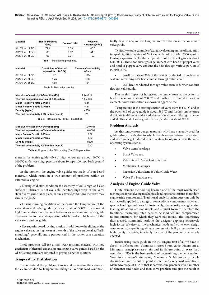
Material Elastic Modulus(GPa) Poisson ratio Rockwell
Hardness(HRC)Al 10% wt. of SiC 77.4 0.33 46.5Al 20% wt. of SiC 86 0.32 51.5Al 30% wt. of SiC 92 0.31 53
Table 1: Mechanical properties.
Material Coefficient of thermal expansion (x10-7 /0k)
Thermal ConductivityW/m.K
Al 10% wt. of SiC 2.0 173Al 20% wt. of SiC 1.75 168Al 30% wt. of SiC 1.55 164
Table 2: Thermal properties.
Modulus of elasticity X-Direction (Pa) 1.2e+011Thermal expansion coefficient X-Direction 1.2e-006Major Poisson's ratio Z-Plane 0.31Minor Poisson's ratio Z-Plane 0.31Density (kg/m3) 4550Thermal conductivity X-Direction (w/m.k) 25
Table 3: Titanium alloy (Ti-834) properties.
Modulus of elasticity X-Direction (Pa) 1.3e+011Thermal expansion coefficient X-Direction 1.6e-006Major Poisson's ratio Z-Plane 0.32Minor Poisson's ratio Z-Plane 0.32Density (kg/m3) 8870Thermal conductivity X-Direction (w/m.k) 230
Table 4: Copper Nickel Silicon alloy (CuNi3Si) properties.

Page 3 of 6
Citation: Srivastva HK, Chauhan AS, Raza A, Kushwaha M, Bhardwaj PK (2016) Comparative Study of Different with al- sic for Engine Valve Guide by using FEM. J Appl Mech Eng 5: 209. doi:10.4172/2168-9873.1000209
Volume 5 • Issue 3 • 1000209J Appl Mech EngISSN:2168-9873 JAME, an open access journal
From the table it is clear that the deflection is varying with change of material it is minimum with Al 30% composites and maximum with CuNi3si Alloy that is 0.124mm. However the guide valve is safe due to very less deformation (Figures 8 and 9).
Table 6 shows the resultant displacement and resultant stress of the guide valve under the different material conditions. under the constant load condition of 10 MPa, and 1 Mpa the safe stress is 23.06 MPa, 21.79MPa, 20.09MPa, 165.39MPa, 286.31MPa, when the guide valve is made up of Al 10% composites, Al 20% composites, Al 30% composites, Titanium Alloy (Ti 834), CuNi3si Alloy, respectively . Which is not exceeded the material yield stress respectively. It is concluded that when the von mises stress are less than the yield stress there the guide
every element and node. It also State that at which node the material is going to fail at which load condition. Therefore this can make our material safe in all load condition. In this way, FEM is applied (using Ansys software) on Valve guide for making a comparative study of Aluminium silicon carbide of different compositions with other materials (which are currently in use):
• Titanium alloy (Ti-834) (used in racing Cars)
• Copper Nickel Silicon Alloy (Cu Ni3Si) (used in locomotive)
At different load conditions such as:
Different temperatures varying from 550°C to 1000°C.
Pressure varying from 10 MPa to 100 MPa.
Modeling has been carried in pro-engineering software. The Engine guide valve is drawn in Pro-E (Figure 1). Sketch of the guide valve is done in the sketcher part of the Pro-Engineering. The section of the guide valve is revolved to 3600 about the central axis to obtain 3D model of guide valve. The inner wall and outer wall is inclined angle 92°.
Finite Element Model of Guide valveAnalysis of guide valve is carried over in following steps Guide valve
model has been modeled in the pro-engineer as shown in Figure 2. For performing the analysis over the guide valve a finite element model is necessary. In order to get the good quality mesh and to maintain the tetrahedron elements, the cap cavity plate is meshed in hyper mesh 12.0 Hyper mesh 12.0 is the product from Altair Hyper Works is a commercially available software package. It mainly used for the finite element modeling of the components. Guide valve as shown in Figure 2 is retrieved in hyper mesh using solid 10 node 92 element type(From Ansys library) is used to mesh the Guide valve and a converged mesh is shown in Figure 3. A Solid 10 node 87 element type is used for thermal analysis.
Result and DiscussionFrom the resultant variation (Figures 4 and 5) the maximum
deformation is 0.0169mm and 0.01436mm is at inside of guide valve when the material is Al 10% Sic and Al 20% Sic and subjected pressure is 10 MPa at top and 1MPa at bottom.
From the resultant variation (Figures 6 and 7) the maximum deformation is 0.0778 mm and 0.124 mm is at inside of guide valve when the material is titanium alloy and CuNi3si alloy and subjected pressure is 10 MPa at top and 1MPa at bottom. The variation of deformation as material is changed is shown in Table 5.
Figure 1: Geometric modeling.
Figure 2: Guide valve.
Figure 3: Meshed model of guide valve.
Figure 4: Deformation variation for Al 10% Sic material.

Page 4 of 6
Citation: Srivastva HK, Chauhan AS, Raza A, Kushwaha M, Bhardwaj PK (2016) Comparative Study of Different with al- sic for Engine Valve Guide by using FEM. J Appl Mech Eng 5: 209. doi:10.4172/2168-9873.1000209
Volume 5 • Issue 3 • 1000209J Appl Mech EngISSN:2168-9873 JAME, an open access journal
valve will be safe. And when the von mises stress are more than the yield stress than the structure will be failed (Figures 10-15).
Case I: When the pressure is 50 MPa and 5 MPa and temperature is 600 °C and 400 °C
The pressure load of 50Mpa at bottom and 5MPa, at top and temperature of 6000 c, at bottom and 4000c at top is applied and deformations and stresses are computed on guide valve (Table 7).
Case II: When the pressure is 100 MPa and 10 MPa and temperature is 600 °C and 400 °C
The pressure load of 100Mpa at bottom and 10MPa, at top and temperature of 600 °C, at bottom and 400°c at top is applied and deformations and stresses are computed on guide valve (Table 8).
Case III: When the pressure is 10 MPa and 1 MPa and temperature is 650°C and 450°C
The pressure load of 10Mpa at bottom and 1MPa, at top and temperature of 650°c, at bottom and 450°c at top is applied and deformations and stresses are computed on guide valve (Table 9).
ConclusionStatic and thermal analysis is carried over Guide valve. The Guide
valve is analyzed for different pressure load cases (Tables 1-5). At a pressure of 10 MPa and 1 MPa and temperature 600° c and 400°c the maximum deformation is 0.124mm and maximum stress is found to be 286.31MPa (CuNi3si Alloy) . Stresses developed for this pressure for all the materials are less than their respective yield strength.
Figure 5: Deformation variation for Al 20% Sic material.
Figure 8: Von mises stress for Al 10% Sic material.
Figure 6: Deformation variation for titanium alloy.
Figure 9: Von mises stress for Al 20% Sic material.
Figure 7: Deformation variation for CuNi3si Alloy.
Result/ Material Al 10% composites Al 20% composites Al 30% composites Titanium Alloy (Ti 834) CuNi3si AlloyDeformation 0.0169mm 0.01436mm 0.0123mm 0.0778mm 0.124mm
Table 5: Deformation with material.

Page 5 of 6
Citation: Srivastva HK, Chauhan AS, Raza A, Kushwaha M, Bhardwaj PK (2016) Comparative Study of Different with al- sic for Engine Valve Guide by using FEM. J Appl Mech Eng 5: 209. doi:10.4172/2168-9873.1000209
Volume 5 • Issue 3 • 1000209J Appl Mech EngISSN:2168-9873 JAME, an open access journal
Load (MPa) Temp 0cMax (bottom) Min (Top) Max (bottom) Min (Top) Material Max. deformation, mm Von-mises, MPa Safety/Failure Material yield stress MPa
10 01 600 400 Al 10% composites 0.0169mm 23.06 MPa Safe 25710 01 600 400 Al 20% composites 0.01436mm 21.79MPa Safe 26310 01 600 400 Al 30% composites 0.0123mm 20.09MPa Safe 26910 01 600 400 Titanium Alloy (Ti 834) 0.0778mm 165.39MPa Safe 91010 01 600 400 CuNi3si Alloy 0.124mm 286.31MPa Safe 550
Table 6: Resultant displacement and resultant stress of the guide valve under the different material conditions.
Figure 10: Deformation variation for Al 30% Sic material.
Figure 12: Deformation variation for Al 30% Sic material.
Figure 11: Vonmises stress for Al 30% Sic material.
Figure 13: Von mises stress for Al 30% Sic material.
Figure 14: Deformation variation for Al 30% Sic material.
Figure 15: Von mises stress for Al 30% Sic material.

Page 6 of 6
Citation: Srivastva HK, Chauhan AS, Raza A, Kushwaha M, Bhardwaj PK (2016) Comparative Study of Different with al- sic for Engine Valve Guide by using FEM. J Appl Mech Eng 5: 209. doi:10.4172/2168-9873.1000209
Volume 5 • Issue 3 • 1000209J Appl Mech EngISSN:2168-9873 JAME, an open access journal
Load (MPa) Temp 0cMax (bottom) Min (Top) Max (bottom) Min (Top) Material Max. deformation, mm Von-mises, MPa Safety/Failure Material yield stress MPa
50 5 600 400 Al 10% composites 0.0564 mm 60MPa Safe 25750 5 600 400 Al 20% composites 0.05034 mm 59.79MPa Safe 26350 5 600 400 Al 30% composites 0.04662 mm 61.94MPa Safe 26950 5 600 400 Titanium Alloy (Ti 834) 0.12907 mm 200.33 MPa Safe 91050 5 600 400 CuNi3si Alloy 0.2268 mm 338.30 MPa Safe 550
Table 7: Deformation and Von mises stress according to respective materials.
Load (MPa) Temp 0cMax (bottom) Min (Top) Max (bottom) Min (Top) Material Max. deformation, mm Von-mises, MPa Safety/Failure Material yield stress MPa
100 10 600 400 Al 10% composites 0.192 mm 129.65 Safe 257100 10 600 400 Al 20% composites 0.16189 mm 131.94 Safe 263100 10 600 400 Al 30% composites 0.1268 mm 132.93 Safe 269100 10 600 400 Titanium Alloy (Ti 834) 0.00986 mm 202.87 Safe 910100 10 600 400 CuNi3si Alloy 0.1816 mm 340.94 Safe 550
Table 8: When the pressure is 10 MPa and 1 MPa, and temperature is 6500c and 4500c.
Load (MPa) Temp 0cMax (bottom) Min (Top) Max (bottom) Min (Top) Material Max. deformation, mm Von-mises, MPa Safety/Failure Material yield stress MPa
100 10 600 400 Al 10% composites 0.020315 mm 25.968 Safe 257100 10 600 400 Al 20% composites 0.01734 mm 26.183 Safe 263100 10 600 400 Al 30% composites 0.01625 mm 29.314 Safe 269
100 10 600 400 Titanium Alloy (Ti 834) 0.0778 mm 216.61 Safe 910
100 10 600 400 CuNi3si Alloy 0.1244 mm 367.18 Safe 550
Table 9: Deformation and Von mises stress according to respective materials.
In the same way when the guide valve is analyzed for the different set of pressure and temperature parameters (i.e., pressure 50 MPa and 5 MPa and temperature is 600°c and 400°c ),( pressure 100 MPa and 10MPa and temperature is 600°c and 400°c), ( pressure is 10 MPa and 1 MPa and temperature is 650°c and 450°c ) the max deformation is found to be 0.2268 mm , 0.1816 mm , 0.1244 mm respectively and max stress is found 338.30 MPa, 340.94 Mpa , 367.18Mpa in CuNi3si Alloy . However it has been observed that at high temperature the stresses produced in Al-SiC composites are very less as compared to other materials at different parameters (pressure & temperature both) From the results obtained finally, it is figured that Al/sicp is suitable materials for high temperature applications i.e., Turbo charged engines. Racing Cars, Diesel Loco Engines, Air craft engines where cost is not a major factor.
References1. Chikahata K, Hayashi K (2000) US patent Publication number US6012703 A.
2. Ahmed S (2013) Development and characterization of Al7075 based hybridcomposites. Paripex Indian j research.
3. Bakshi SR, Di Wang, Price T, Agarwal A (2009) Composite Material-Aluminium Silicon Alloy: A Review. Paripex Indian j research.
4. Singla M, Dwivedi DD, Singh L, Chawla V (2009) Development of Aluminium based Silicon carbide particulate metal matrix composits. 8: 455-467.
5. Saheb DA (2011) Aluminum Silicon Carbide and Aluminum Graphite Particulate Composites ARPN J Engineering and Applied Sciences 6: 41-46.
6. Singh R, Singla ER (2012) Tribological characterization of Aluminium-Silicon carbide composite prepared by mechanical alloying. Int J Applied Engineering Research.
Citation: Srivastva HK, Chauhan AS, Raza A, Kushwaha M, Bhardwaj PK (2016) Comparative Study of Different with al- sic for Engine Valve Guide by using FEM. J Appl Mech Eng 5: 209. doi:10.4172/2168-9873.1000209