Embed Size (px)
Citation preview

Research Article
Yoshida, J Appl Mech Eng 2017, 6:4DOI: 10.4172/2168-9873.1000276
Research Article Open Access
Journal of Applied Mechanical EngineeringJo
urna
l of A
pplied Mechanical Engineering
ISSN: 2168-9873
Volume 6 • Issue 4 • 1000276J Appl Mech Eng, an open access journalISSN: 2168-9873
*Corresponding author: Yoshida S, Honda R&D Co Ltd. Aircraft Engine R&DCenter, 1-4-1 Chuo, Wako-shi, Saitama, 351-0193 Japan, Tel: 91-120-234 1028;E-mail: [email protected]
Received June 09, 2017; Accepted July 19, 2017; Published July 24, 2017
Citation: Yoshida S (2017) Effect of Epoxy Functional Groups on the Properties of Carbon Fiber-Epoxy Composites. J Appl Mech Eng 6: 276. doi: 10.4172/2168-9873.1000276
Copyright: © 2017 Yoshida S. This is an open-access article distributed under the terms of the Creative Commons Attribution License, which permits unrestricted use, distribution, and reproduction in any medium, provided the original author and source are credited.
Effect of Epoxy Functional Groups on the Properties of Carbon Fiber-Epoxy CompositesYoshida S* Honda R&D Co Ltd. Aircraft Engine R&D Center, 1-4-1 Chuo, Wako-shi, Saitama, 351-0193 Japan
Abstract
Matrix resins of carbon fiber-epoxy composites with different numbers of epoxy functional groups were prepared, and their properties were compared to optimize the matrix resin composition. To understand the bonding strengths between the carbon fiber and epoxy resins in monofilaments and micro-sized resin beads, the interfacial shear strength (IFSS) was measured using the microdroplet technique. The bonding strength for the T800SC carbon fibers was maximized for a 50:50 (wt/wt) ratio of epoxy resins containing four and three epoxy groups per molecule, respectively, and that for the IMS60 carbon fibers was maximized for a 70:25:5 (wt/wt/wt) ratio of epoxy resins containing four, three, and two epoxy groups per molecule, respectively. The transverse tensile, in-plane shear, interlaminar shear, and compression strengths were higher for the interfacial-shear-strength-optimized T800SC-epoxy mixture than for the T800SC-100% basic bisphenol A epoxy material. These composite materials exhibit a potential to be used in applications such as automobiles and aircraft as lightweight, high-strength, and rigid materials.
Keywords: Epoxy; Carbon fiber; Composite; Functional group;Matrix resin; Mechanical properties
IntroductionComposite materials that combine high-strength fibers and epoxy
resins, such as carbon-fiber-reinforced plastics (CFRPs), are widely used in aerospace and automobile industries as lightweight, high-strength, and rigid materials [1]. Currently, considerable research is focused on optimizing the properties of and bonding strength between the carbon fibers and matrix resins in these composites.
Surface treatment of carbon fibers, such as anodization [2-7] or plasma [8-14] or γ-ray [15,16] treatment, is conventionally used to improve the bonding strength between the carbon fiber and epoxy resin. Park et al. [2] showed that the anodic oxidation of carbon fibers led to an increase in the surface free energy of the fibers and played an important role in enhancing adhesion at the interfaces between the fibers and resin matrix. Yumitori and Nalanishi [3,4] anodized fibers in acid and alkaline solutions and examined their interfacial shear strength (IFSS) using single-fiber fragmentation tests. The IFSS of epoxy resins combined with anodized carbon fibers was more than 30% higher than that of resins combined with untreated fibers [3,4]. In addition, X-ray photoelectron spectroscopy analysis revealed the increase in the surface oxygen concentration and in the number of surface functional groups, such as OH, C=O, and COOH, after anodization [2-5,7]. Qian et al. [6] reported that the interfacial strength between carbon fibers and the matrix resins improved after surface electrochemical oxidation and sizing, and this treatment also led to an increase in the surface roughness of the fibers. Gulyás et al. [6] posited that the functional groups formed on the carbon fiber surfaces depend on the anodizing electrolyte, whereas their number and concentration depend on the oxidation voltage. However, excessive anodization leads to the formation of a weak boundary layer [7] and causes pitting on the carbon fiber surfaces, leading to a decrease in their interlaminar shear strength (ILSS) [17].
Other researchers have investigated the effects of various plasma surface treatments, such as nitrogen, argon, oxygen, and tetrafluoromethane treatments, on carbon fiber surfaces [8-12]. Bogoeva-Gaceva et al. [8] showed that plasma treatment increased the IFSS of fiber-epoxy composites by more than 10% relative to that of an untreated composite. In addition, Farrow et al. [9,10] demonstrated
that nitrogen-containing functional groups embedded in plasma effectively increase the IFSS of the composites. Lin and Yip [11] posited that nitrogen surface functionalities could easily be formed by nitrogen ion bombardment, and the treated carbon fiber composites exhibited higher transverse tensile stress. Bian et al. [12] reported that oxygen and nitrogen/hydrogen plasma treatments were the most effective for introducing oxygen-containing functionalities on the fiber surface and for improving the IFSS of the composites with the treated fibers. Another plasma approach is copolymerization of the carbon surface by acrylic acid-hexane, allyl alcohol-hexane, or allylamine-octadiene [13-14]. Plasma treatment in acrylic acid-hexane and allylamine-octadiene gases presumably increases the IFSS because the acrylic acid-amine functionalities react with the epoxide groups [13].
The third typical strengthening treatment is graft polymerization onto carbon fiber surfaces by γ-ray irradiation. Xu et al. [15,16] reported that treating carbon fibers by γ-ray irradiation, acrylic acid immersion, and an oxidation-reduction process increases the ILSS of the fiber-epoxy composites by 15% relative to that of the untreated carbon fiber-epoxy composites (fabricated by reacting grafted functional groups with epoxy).
The effect of ammonia solution applied to carbon fibers at a high temperature and pressure has also been discussed [17]. This treatment improves the ILSS of the fiber-epoxy composites by more than 30%, most likely because the ammonia solution exerts a dual physical etching and chemical effect on the fibers [17]. However, Dai et al. [18] showed that heat-treating carbon fibers disrupted some of the reactive functional groups, thereby decreasing the IFSS. Carbon fiber treatment has been more completely reviewed elsewhere [19,20].

Page 2 of 7
Citation: Yoshida S (2017) Effect of Epoxy Functional Groups on the Properties of Carbon Fiber-Epoxy Composites. J Appl Mech Eng 6: 276. doi: 10.4172/2168-9873.1000276
Volume 6 • Issue 4 • 1000276J Appl Mech Eng, an open access journalISSN: 2168-9873
Carbon fibers for CFRP: The commercial products TORAYCA® T800-SC (Toray Industries, Inc.) and Tenax® IMS60 (Toho Tenax Co., Ltd.) were selected as representative intermediate-modulus and high-tensile-strength carbon fibers to be used in aircraft engine parts. TORAYCA® T800-SC and Tenax® IMS60, hereafter denoted CA and CB, respectively, were evaluated as received.
However, few previously published studies have investigated the effect of the epoxy matrix composition on the mechanical properties of carbon fiber-epoxy composites. As mentioned above, interfacial adhesion between the fibers and epoxy resin is chiefly governed by the chemical reactions of the functional groups. Therefore, the fiber-epoxy interfacial condition might reasonably be understood by investigating the epoxy matrix composition.
In this work, we attempt to optimize the epoxy matrix resin design to improve the mechanical properties of commercial carbon fiber composites, focusing on the number of epoxy functional groups per molecule, which affects the physical properties of the carbon fiber-epoxy composites. The IFSS between the carbon fiber and epoxy resins is evaluated using the microdroplet technique. This technique was chosen because it is much easier to make samples to measure the IFSS using this method than using a conventional method such as single filament tensile testing, ASTM D3379. Two carbon fibers of intermediate modulus and high tensile strength were selected as the reinforced fibers in the composites, and the matrix resins were mixtures of commercial epoxy resins with two to four epoxy functional groups per molecule. Once the matrix resin composition was optimized based on the IFSS results, it was incorporated into a carbon fiber-resin composite. The mechanical properties of this composite, namely the transverse tension, compression strength, in-plane shear strength, and ILSS, were evaluated and compared with those of a carbon fiber-100% basic bisphenol A epoxy resin system, which was used as a reference. The evaluated properties were selected because they are affected by the interfacial condition such as the bonding strength between the carbon fibers and matrix resin.
The results of this study can be used to optimize the matrix resin composition for aircraft engine parts composed of CFRPs.
ExperimentalMaterials
Thermosetting matrix resin for CFRPs: Five types of base epoxy resins were used in this investigation. Figure 1 shows the product names, generic chemical names, and material suppliers. All the materials were used without modification. Both bisphenol A epoxy resins BPAE1 and BPAE2 have the same basic chemical structure; however, their average molecular weights (Mn) differ by a factor of greater than 10 (BPAE1: Mn=380, BPAE2: Mn=3000). An aromatic amine was used as the curing agent, as shown in Figure 2. No accelerators or additives were used.
Mixing of the two to four epoxy ingredients with diaminodiphenyl sulfone was performed at approximately 150°C according to the weight percentages, as shown in Table 1. The mixing was performed at 260 rpm for 5 min in a mixer with planetary-type blades. The good dispersion of the mixed epoxy resin was confirmed in a quantitative analysis using infrared (IR) spectroscopy, as described in the study by Yoshida [21].
TORAYCA® T800-SC and Tenax® IMS60 carbon fibers were paired with EP-a resins and EP-b resins, respectively. A basic bisphenol A epoxy resin (EP-c) was designed to be used as a comparison standard. The candidate compositions of EP-a and EP-b resins were determined by multiple classification analysis using the JMP® 9 software (SAS Institute Inc.). The multiple classification analysis was conducted with the epoxy resin composition design as the factors and the IFSS per each carbon fiber and ease of kneading by IR spectroscopy evaluation above as the responses. The purpose of the analysis was to screen for the appropriate epoxy resin composition for good bonding strength between the fiber and resin and good kneading processability.
Figure 1: Chemical structures of the basic epoxy resins used in this study: (a) glycidyl amine epoxy (Araldite® MY721, Huntsman Corporation), (b) triglycidyl-p-aminophenol (jER630, Mitsubishi Chemical Corporation), (c) tetramethyl biphenol epoxy (YX4000, Mitsubishi Chemical Corporation), (d) BPAE1 (jER828, Mitsubishi Chemical Corporation; Mn = 380) and BPAE2 (jER1006FS, Mitsubishi Chemical Corporation; Mn = 3000).
Figure 2: Chemical structure of the curing agent diaminodiphenyl sulfone (Aradur ®976-1, Huntsman Corporation).
Epoxy weight percentage (%)Curing agent
weightpercentage (%)
Sample # GDAE TPAP TBPE BPAE1 BPAE2 DDSEP-a-1 40 40 - - 20 66EP-a-2 40 50 10 - 10 62EP-a-3 45 30 20 - 5 58EP-a-4 30 30 30 - 10 55EP-a-5 30 10 50 - 10 48EP-a-6 30 15 50 - 5 49EP-a-7 70 10 15 - 5 57EP-b-1 60 20 5 - 15 61EP-b-2 70 10 10 - 10 58EP-b-3 70 15 10 - 5 59EP-b-4 25 40 30 - 5 56EP-b-5 30 50 15 - 5 61EP-b-6 30 40 10 - 20 63EP-b-7 30 10 50 - 10 48EP-b-8 20 10 60 - 10 45EP-b-9 20 - 75 - 5 41EP-c - - - 80 20 30
Table 1: Components of resin mixtures evaluated by IR spectroscopy.

Page 3 of 7
Citation: Yoshida S (2017) Effect of Epoxy Functional Groups on the Properties of Carbon Fiber-Epoxy Composites. J Appl Mech Eng 6: 276. doi: 10.4172/2168-9873.1000276
Volume 6 • Issue 4 • 1000276J Appl Mech Eng, an open access journalISSN: 2168-9873
CFRP preparation: Two CFRP prepregs based on the EP-a-1 or EP-c matrix resins were prepared. Because the highest IFSS in the evaluated system was obtained by combining EP-a-1 with carbon fiber CA, it was used as the reinforced fiber. Once the carbon fibers were aligned, they were impregnated with matrix resins at 80°C under a pressure of 0.2 MPa. The resin-impregnated unidirectional carbon fibers were placed onto the release sheets under 0.2 MPa pressure, and these sheets were rewound on the roll.
IFSS measurements: The IFSS was measured using the microdroplet technique and a Model HM410 instrument (Tohei Sangyo Co. Ltd.). A monofilament was extracted from a CA and CB carbon fiber strand and fixed on a mounting. The EP-a-1-7, EP-b-1-9, and EP-c resin mixtures were heated to 130°C for 3 min, reducing their viscosity for easier sampling. Small amounts of resins were collected onto a spatula and placed on the monofilament that is already fixed on the mounting, and the mounted composite was cured at 180°C for 2 h. The mounting with its monofilament and cured resins was then placed on the test instrument, and the shear load required to withdraw a resin droplet (<80 μm) from the fiber was measured. The IFSS was calculated as follows:
τπ
=FDL
(1)
Where F is the shear load required to withdraw a resin droplet (mN), D is the diameter of the monofilament (μm), and L is the length of the filament covered by a resin bead (μm). From each sample, 5-8 droplets were withdrawn at 23°C under dry conditions. The test speed was 0.12 mm/min.
CFRP flat panel preparation: Flat panels of varying thicknesses (300 mm × 300 mm × 2-4.5 mm) were prepared for mechanical testing of the EP-a-1-CA and EP-c-CA prepregs. The CFRPs for hand layup were pressed and cured using an autoclave (Model AC-400/20; ASHIDA MFG Co., Ltd.). A fiber volume of 60% was achieved using a two-step curing process. First, the autoclave was heated to 150°C at 3°C/min and maintained at this temperature for 1 h. Next, the autoclave was heated to 180°C at 3°C/min and maintained at 180°C for 2 h. During curing, individual panels were subjected to a pressure of 5 kgf/cm2. The cured flat panels were cooled to below 70°C and depressurized. All the flat panels were machined by end milling, meeting the tolerance requirement of below ± 0.3 mm. The panels were prepared without any specific defects, such as voids, delamination, or fiber weave, as verified by visual inspection. All the prepared panels were also checked by ultrasonic inspection to evaluate internal defects. A 5-MHz phased array ultrasonic system (Matrixeye 64; Toshiba Co., Ltd.) was used and scanned by hand at a room temperature. The inspection probe was calibrated before each inspection, and a 5-mm-diameter standard defect was used for calibration. No defects were detected in the panels.
Mechanical Testing of CFRPsThe composite mechanical properties of the EP-a-1-CA and EP-c-
CA CFRPs were evaluated by transverse tension, compression, in-plane shear, and interlaminar shear testing. These tests were appropriate to be used to understand the material anisotropic properties, and they are often used to obtain structural part design data.
Transverse tension and in-plane shear tests were performed according to the ASTM D3039 and ASTM D3518 standards, respectively. The specimens were 200 mm long, 12 mm wide and 2 mm thick. The testing speed was 2 mm/min, and eight specimens were tested at each condition. The transverse tensile and in-plane shear strengths were calculated using eqns. (2) and (3), respectively.
mm
22Fbh
σ = (2)
mm
12F2bh
τ = (3)
Here, Fm is the maximum shear or tensile load to failure (N), and b and h denote the width and thickness, respectively, of the test specimen (mm). The transverse tensile strength and in-plane shear modulus of the chord direction and the shear strain were calculated using eqns. (4) to (6), respectively:
chord 2222
l
E σε
∆=
∆ (4)
chord 1212
12
G τγ
∆=∆
(5)
12 l tγ ε ε= − (6)
Here, Δ is the strength or strain difference where γ is 0.1% or 0.3% and εl is 0.1% or 0.3%. εl and εt are the strains in the chord and transverse directions, respectively. The Poisson ratios of the transverse tensile to in-plane shear were calculated using eqn. (7):
l
t
ευε
∆= −
∆ (7)
The compression tests were conducted according to the ASTM D6641 standard. The specimens were 150 mm long, 20 mm wide and 4.5 mm thick. The testing speed was 1.3 mm/min, and eight specimens were tested under each condition. The compression strength, modulus, and Poisson ratios were calculated using eqns. (8) to (10), respectively:
cu fPFbh
= (8)
cuc
t
FEε
∆=∆
(9)
c l
t
ενε
∆= −
∆ (10)
Where, Pf is the maximum load to failure.
The interlaminar shear tests were conducted according to the ASTM D2344 standard. The specimens were 27 mm long, 9 mm wide and 4.5 mm thick. The testing speed was 1 mm/min, and 10 specimens were tested under each condition. The ILSS was calculated using eqn. (11):
sbs mPF 0.75bh
= × (11)
Where, Pm is the maximum load to failure.
The above tests were conducted using an Instron Model 1185 at 23°C under dry conditions.
ResultsIFSS measurements
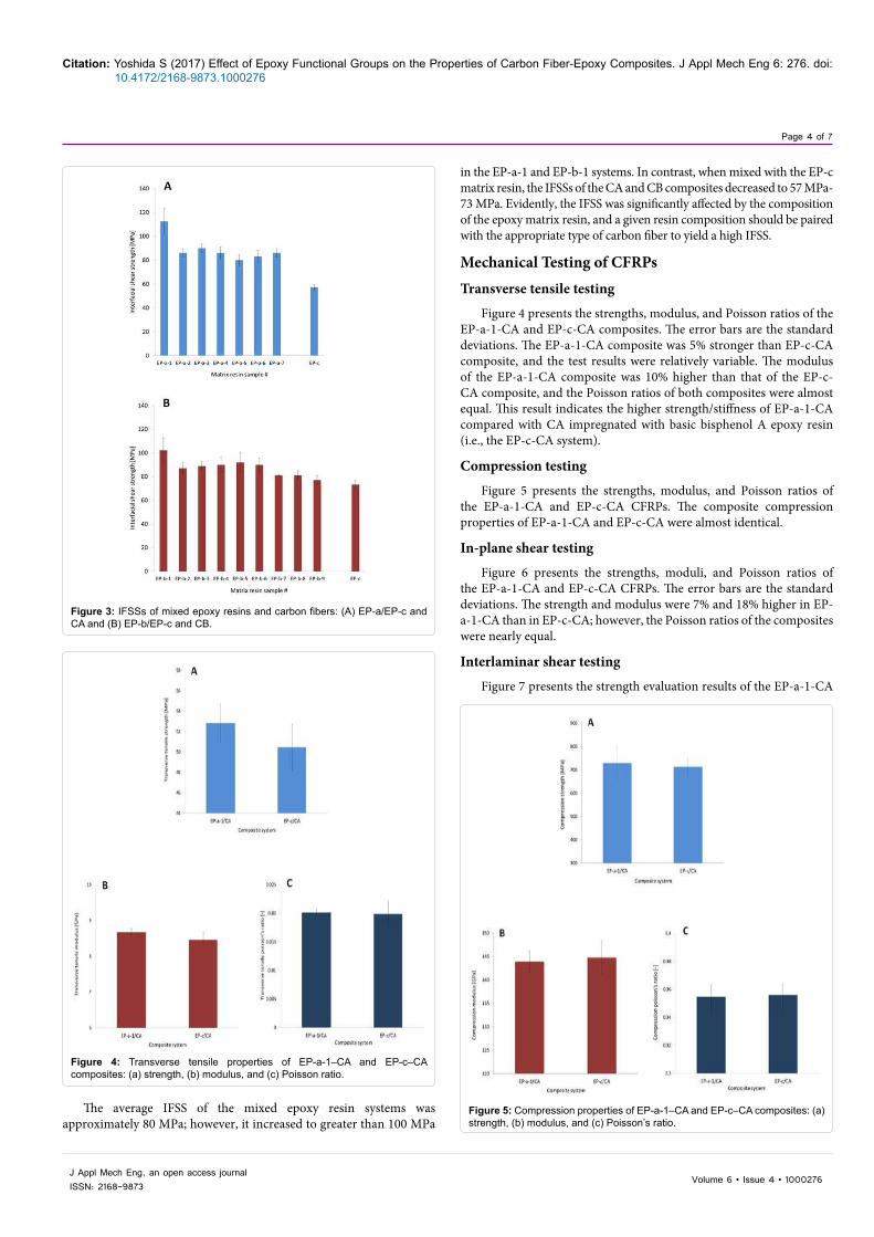
Figure 3 presents the IFSS evaluation results. The bar heights are the average IFSS values, and the error bars are the standard deviations. The highest IFSS was achieved for the EP-a-1-CA and EP-b-1-CB composites. The shear strengths of these composites were 30%-50% higher than those of the EP-c and basic bisphenol A epoxy resin composites. However, the standard deviation was increased at higher IFSS because fiber breakage was enhanced under high interfacial shear loads.
Page 4 of 7
Citation: Yoshida S (2017) Effect of Epoxy Functional Groups on the Properties of Carbon Fiber-Epoxy Composites. J Appl Mech Eng 6: 276. doi: 10.4172/2168-9873.1000276
Volume 6 • Issue 4 • 1000276J Appl Mech Eng, an open access journalISSN: 2168-9873
in the EP-a-1 and EP-b-1 systems. In contrast, when mixed with the EP-c matrix resin, the IFSSs of the CA and CB composites decreased to 57 MPa-73 MPa. Evidently, the IFSS was significantly affected by the composition of the epoxy matrix resin, and a given resin composition should be paired with the appropriate type of carbon fiber to yield a high IFSS.
Mechanical Testing of CFRPsTransverse tensile testing
Figure 4 presents the strengths, modulus, and Poisson ratios of the EP-a-1-CA and EP-c-CA composites. The error bars are the standard deviations. The EP-a-1-CA composite was 5% stronger than EP-c-CA composite, and the test results were relatively variable. The modulus of the EP-a-1-CA composite was 10% higher than that of the EP-c-CA composite, and the Poisson ratios of both composites were almost equal. This result indicates the higher strength/stiffness of EP-a-1-CA compared with CA impregnated with basic bisphenol A epoxy resin (i.e., the EP-c-CA system).
Compression testing
Figure 5 presents the strengths, modulus, and Poisson ratios of the EP-a-1-CA and EP-c-CA CFRPs. The composite compression properties of EP-a-1-CA and EP-c-CA were almost identical.
In-plane shear testing
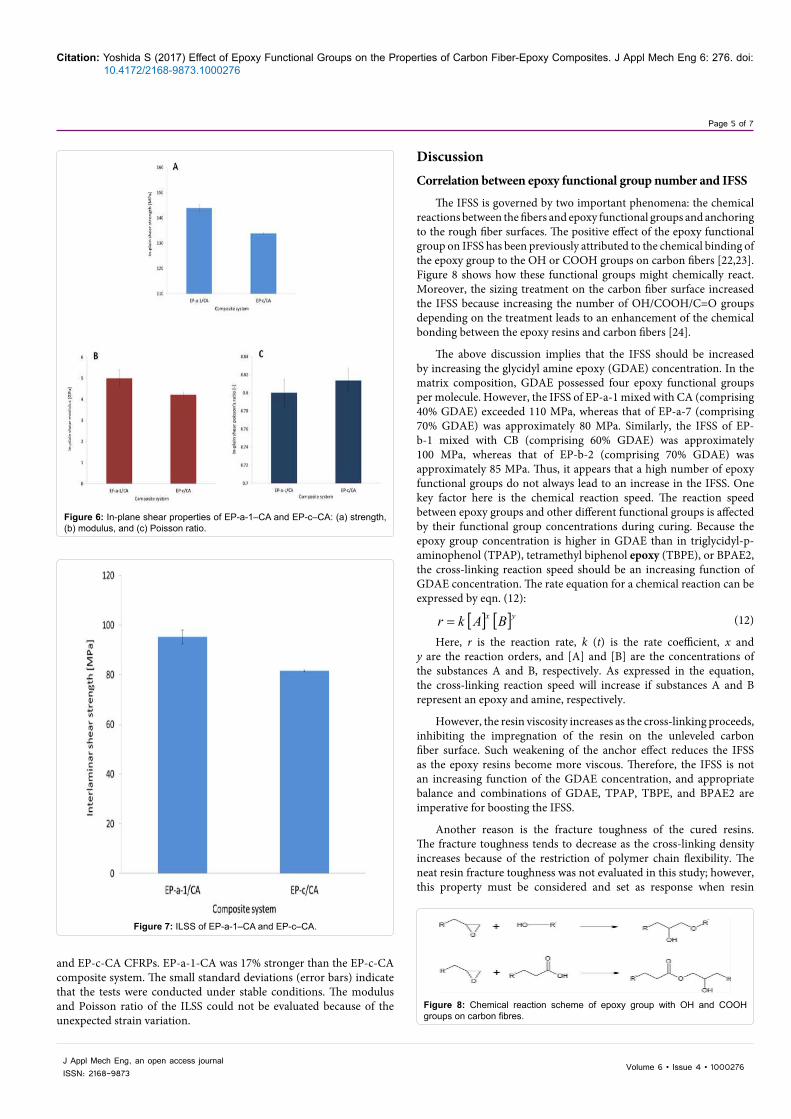
Figure 6 presents the strengths, moduli, and Poisson ratios of the EP-a-1-CA and EP-c-CA CFRPs. The error bars are the standard deviations. The strength and modulus were 7% and 18% higher in EP-a-1-CA than in EP-c-CA; however, the Poisson ratios of the composites were nearly equal.
Interlaminar shear testing
Figure 7 presents the strength evaluation results of the EP-a-1-CA
Figure 3: IFSSs of mixed epoxy resins and carbon fibers: (A) EP-a/EP-c and CA and (B) EP-b/EP-c and CB.
Figure 4: Transverse tensile properties of EP-a-1–CA and EP-c–CA composites: (a) strength, (b) modulus, and (c) Poisson ratio.
The average IFSS of the mixed epoxy resin systems was approximately 80 MPa; however, it increased to greater than 100 MPa
Figure 5: Compression properties of EP-a-1–CA and EP-c–CA composites: (a) strength, (b) modulus, and (c) Poisson’s ratio.
Page 5 of 7
Citation: Yoshida S (2017) Effect of Epoxy Functional Groups on the Properties of Carbon Fiber-Epoxy Composites. J Appl Mech Eng 6: 276. doi: 10.4172/2168-9873.1000276
Volume 6 • Issue 4 • 1000276J Appl Mech Eng, an open access journalISSN: 2168-9873
and EP-c-CA CFRPs. EP-a-1-CA was 17% stronger than the EP-c-CA composite system. The small standard deviations (error bars) indicate that the tests were conducted under stable conditions. The modulus and Poisson ratio of the ILSS could not be evaluated because of the unexpected strain variation.
DiscussionCorrelation between epoxy functional group number and IFSS
The IFSS is governed by two important phenomena: the chemical reactions between the fibers and epoxy functional groups and anchoring to the rough fiber surfaces. The positive effect of the epoxy functional group on IFSS has been previously attributed to the chemical binding of the epoxy group to the OH or COOH groups on carbon fibers [22,23]. Figure 8 shows how these functional groups might chemically react. Moreover, the sizing treatment on the carbon fiber surface increased the IFSS because increasing the number of OH/COOH/C=O groups depending on the treatment leads to an enhancement of the chemical bonding between the epoxy resins and carbon fibers [24].
The above discussion implies that the IFSS should be increased by increasing the glycidyl amine epoxy (GDAE) concentration. In the matrix composition, GDAE possessed four epoxy functional groups per molecule. However, the IFSS of EP-a-1 mixed with CA (comprising 40% GDAE) exceeded 110 MPa, whereas that of EP-a-7 (comprising 70% GDAE) was approximately 80 MPa. Similarly, the IFSS of EP-b-1 mixed with CB (comprising 60% GDAE) was approximately 100 MPa, whereas that of EP-b-2 (comprising 70% GDAE) was approximately 85 MPa. Thus, it appears that a high number of epoxy functional groups do not always lead to an increase in the IFSS. One key factor here is the chemical reaction speed. The reaction speed between epoxy groups and other different functional groups is affected by their functional group concentrations during curing. Because the epoxy group concentration is higher in GDAE than in triglycidyl-p-aminophenol (TPAP), tetramethyl biphenol epoxy (TBPE), or BPAE2, the cross-linking reaction speed should be an increasing function of GDAE concentration. The rate equation for a chemical reaction can be expressed by eqn. (12):
[ ] [ ]yx BAkr = (12)
Here, r is the reaction rate, k (t) is the rate coefficient, x and y are the reaction orders, and [A] and [B] are the concentrations of the substances A and B, respectively. As expressed in the equation, the cross-linking reaction speed will increase if substances A and B represent an epoxy and amine, respectively.
However, the resin viscosity increases as the cross-linking proceeds, inhibiting the impregnation of the resin on the unleveled carbon fiber surface. Such weakening of the anchor effect reduces the IFSS as the epoxy resins become more viscous. Therefore, the IFSS is not an increasing function of the GDAE concentration, and appropriate balance and combinations of GDAE, TPAP, TBPE, and BPAE2 are imperative for boosting the IFSS.
Another reason is the fracture toughness of the cured resins. The fracture toughness tends to decrease as the cross-linking density increases because of the restriction of polymer chain flexibility. The neat resin fracture toughness was not evaluated in this study; however, this property must be considered and set as response when resin
Figure 6: In-plane shear properties of EP-a-1–CA and EP-c–CA: (a) strength, (b) modulus, and (c) Poisson ratio.
Figure 7: ILSS of EP-a-1–CA and EP-c–CA.
Figure 8: Chemical reaction scheme of epoxy group with OH and COOH groups on carbon fibres.
Page 6 of 7
Citation: Yoshida S (2017) Effect of Epoxy Functional Groups on the Properties of Carbon Fiber-Epoxy Composites. J Appl Mech Eng 6: 276. doi: 10.4172/2168-9873.1000276
Volume 6 • Issue 4 • 1000276J Appl Mech Eng, an open access journalISSN: 2168-9873
composition screening is conducted using multiple classification analysis.
Correlation between IFSS and composite mechanical properties
An IFSS difference of greater than 100% was observed between EP-a-1-CA and EP-c-CA. However, their strength difference was 18% for in-plane shear strength, 7% for ILSS, and 5% for transverse tensile strength for epoxy-CA composites. This result indicates a third important contributor to the IFSS: the mechanical strength of the composite. As mentioned in the “experimental” section, the fiber volume of the evaluated composites was 60%, and the mechanical properties of the epoxy resins were negligible, compromising the carbon fiber performance. Therefore, we can reasonably suppose that the mechanical properties of carbon fibers strongly affect the composite testing results according to the rule of mixtures. However, it is notable that the in-plane shear strength shows a relatively credible strength difference, compared with the ILSS, transverse tensile strength, and compression strength. During the in-plane shear test, 45° aligned fibers were rotated in the vertical direction. This load process was similar to the IFSS test condition because main interfacial load mode was in-plane shear. Therefore, the in-plane shear strength was relatively sensitive to IFSS. Regarding the modulus, the composite property difference between EP-a-1-CA and EP-c-CA was 2% transverse tensile and 19% in-plane shear, and EP-a-1-CA exhibited a higher stiffness in both tests relative to EP-c-CA. In addition, the higher modulus of the EP-a-1-CA composites is derived from high cross-linking enabled by the high concentration of the epoxy functional groups. There is little difference in the Poisson’s ratios of the transverse tensile and in-plane shear.
In the compression tests, the mechanical property difference between EP-a-1-CA and EP-c-CA was negligible. The strength of the two composites only differed by 1.3%, and their moduli and Poisson ratios only differed by less than 1%. The near-identical performance of EP-a-1 and EP-c in the compression tests can be explained by the low fracture toughness of the matrix resin caused by the high cross-linking concentration. The first epoxy resin crack damage during the initial compression test loading is caused by crack propagation between the carbon fiber surface and epoxy resin, leading to fatal failure of the test specimens. The fracture mode during the crack propagation was not shear, but interfacial delamination and opening fracture, mode I. Therefore, the EP-a-1-CA composite lost its advantage of strength over EP-c-CA under compression testing.
The discussion above indicates that IFSS may be effective for the composite property optimization regarding in-plane shear; however, a different screening method must be adopted to optimize the tensile and compression properties for matrix resin composition design development.
Mechanical testing
In general, the test results of the EP-a-1-CA composite were more variable than those of EP-c-CA composite. This variation is attributed to the nonuniformity of the resin mixture, despite rigorous checking of the dispersion condition using a previously proposed method [21]. Moreover, the variation was exaggerated in the in-plane shear test result. This finding suggests a role for variations in the fiber alignment of the composite, as the resin-impregnated carbon fiber prepregs were piled up manually because the fiber orientation was 45°. Small misalignments are a recognized cause of deviations in the mechanical properties of a material.
The in-plane shear test profiles of the EP-a-1-CA and EP-c-
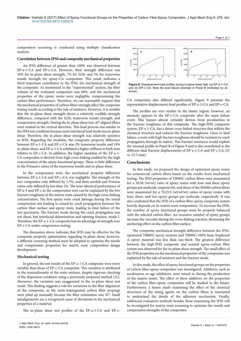
CA composites also differed significantly. Figure 9 presents the representative displacement-load profiles of EP-a-1-CA and EP-c-CA.
The profiles are very similar in the elastic region; however, an anomaly appears in the EP-c-CA composite after the main failure event. This feature almost certainly derives from peculiarities in the fracture toughness of this composite. The high-IFSS composite system, EP-a-1-CA, has a dense cross-linked structure that stiffens the chemical structure and reduces the fracture toughness. Close to fatal failure, a resin with high fracture toughness should be resistant to crack propagation through its matrix. This fracture resistance would explain the unusual profile in Panel B of Figure 9 and is also manifested in the different fatal fracture displacements of EP-a-1-CA and EP-c-CA (21 vs. 23.5 mm).
ConclusionsIn this study, we proposed the design of optimized epoxy resins
for commercial carbon fibers based on the results from mechanical testing. The IFSS properties of T800SC carbon fibers were maximized for a 50:50 (wt/wt) ratio of epoxy resins with four and three epoxy groups per molecule, respectively, and those of the IMS60 carbon fibers were maximized for a 70:25:5 (wt/wt/wt) ratios of epoxy resins with four, three, and two epoxy groups per molecule, respectively. It was also confirmed that the IFSS of a carbon fiber-epoxy composite system heavily depends on its matrix resin composition. To increase the IFSS, the number of epoxy functional groups must be properly balanced with the selected carbon fiber. An excessive number of epoxy groups increase the viscosity during the cross-linking reaction, decreasing the anchoring effect on the carbon fiber surface.
The composite mechanical strength difference between the IFSS-optimized T800SC-epoxy mixture and T800SC-100% basic bisphenol A epoxy material was less than one-third. The greatest difference between the high-IFSS composite and normal epoxy-carbon fiber system was observed for the in-plane shear strength. The small effect of the IFSS properties on the mechanical properties of the composites was explained by the rule of mixtures and the fracture mode.
In this study, the effect of epoxy functional groups on the properties of carbon fiber-epoxy composites was investigated. Additives, such as accelerators or age inhibitors, were mixed in during the production of the matrix resins. The effect of these additives on the properties of the carbon fiber-epoxy composites will be studied in the future. Furthermore, a future study examining the effect of the chemical structures of the sizing agents on the carbon fibers is warranted to understand the details of the adhesion mechanism. Finally, additional evaluation methods besides those examining the IFSS will be investigated for matrix resin screening to optimize the tensile and compression strengths of the composites.
Figure 9: Displacement-load profiles during in-plane shear test: (a) EP-a-1–CA and (b) EP-c–CA. Note the post failure anomaly in Panel B (indicated by an arrow).

Page 7 of 7
Citation: Yoshida S (2017) Effect of Epoxy Functional Groups on the Properties of Carbon Fiber-Epoxy Composites. J Appl Mech Eng 6: 276. doi: 10.4172/2168-9873.1000276
Volume 6 • Issue 4 • 1000276J Appl Mech Eng, an open access journalISSN: 2168-9873
References
1. Garton A, McLean PD, Wiebe W, Densley RJ (1986) Exposure of cross-linkedepoxy resins to the space environment. J Appl Polym Sci 32: 3941-3957.
2. Park SJ, Chng YH, Kim YC, Rhee KY (2010) Anodization of carbon fibers on interfacial mechanical properties of epoxy matrix composites. J NanosciNanotechno 10: 117-121.
3. Yumitori S, Nalanishi Y (1996) Effect of anodic oxidation of coal tar pitch-based carbon fibre on adhesion in epoxy matrix: Part 1. Comparison between H2SO4and NaOH solutions. Compos Part A-Appl S 27: 1051-1058.
4. Yumitori S, Nalanishi Y (1996) Effect of anodic oxidation of coal tar pitch-based carbon fibre on adhesion in epoxy matrix: Part 2. Comparative study of three alkaline solutions. Compos Part A-Appl S 27: 1059-1066.
5. Qian X, Wang X, Yang QO, Chen Y, Yan Q (2012) Surface structural evolvement in electrochemical oxidation and sizing and its effect on carbon fiber/epoxy composites properties. J Reinf Plast Comp 31: 999-1008.
6. Gulyás J, Földes E, Lázár A, Pukánszky B (2001) Electrochemical oxidationof carbon fibres: Surface chemistry and adhesion. Compos Part A-Appl S 32: 353-360.
7. Nakao F, Takenaka Y, Asai H (1992) Surface characterization of carbon fibres and interfacial properties of carbon fibre composites. Composites 23: 365-372.
8. Bogoeva-Gaceva G, Mäder E, Haüssler L, Dekanski, A (1997) Characterization of the surface and interphase of plasma-treated HM carbon fibres. Compos Part A-Appl S 28: 445-452.
9. Farrow GJ, Atkinson KE, Fluck N, Jones C (1995) Effect of low-power airplasma treatment on the mechanical properties of carbon fibres and the interfacial shear strength of carbon fibre-epoxy composites. Surf Interface Anal 23: 313-318.
10. Farrow GJ, Jones C (1994) The effect of low power nitrogen plasma treatment of carbon fibres on the interfacial shear. J Adhesion 45: 29-42.
11. Lin SS, Yip PW (1994) Improved mechanical strengths of epoxy compositesobtained from Ion beam treated carbon fibers. Material Research Society Symposium Proceedings 318: 381-386.
12. Bian XS, Ambrosio L, Kenny JM, Nicolais L, Occhiello E, et al. (1991) The
effects of surface treatments of fibers on the interfacial properties in single-fiber composites. J Adhes Sci Technol 5: 377-388.
13. Lopattananon N, Kettle AP, Tripathi D, Beck AJ, Duval E, et al. (1999) Interfacemolecular engineering of carbon-fiber composites. Compos Part A-Appl S 30: 49-57.
14. Kettle AP, Beck AJ, O’Toole L, Jones FR, Short RD (1997) Plasma polymerisation for molecular engineering of carbon-fibre surfaces for optimised composites. Compos Sci Technol 57: 1023-1032.
15. Xu Z, Huang Y, Zhang C, Liu L, Zhang Y, et al. (2007) Effect of γ-ray irradiation grafting on the carbon fibers and interfacial adhesion of epoxy composites. Compos Sci Technol 67: 3261-3270.
16. Xu Z, Chen L, Huang Y, Li J, Wu X, et al. (2008) Wettability of carbon fibers modified by acrylic acid and interface properties of carbon fiber/epoxy. Eur Polym J 44: 494-503.
17. Meng LH, Chen ZW, Song XL, Liang YX, Huang YD, et al. (2009) Influence of high temperature and pressure ammonia solution treatment on interfacial behavior ofcarbon fiber/epoxy resin composites. J Appl Polym Sci 113: 3436-3441.
18. Dai Z, Zhang B, Shi F, Li M, Zhang Z, et al. (2011) Effect of heat treatment oncarbon fiber surface properties and fibers/epoxy interfacial adhesion. Appl Surf Sci 257: 8457-8461.
19. Drzal LT, Rich MF, Lloyd PF (1982) Adhesion of graphite fibers to epoxy matrices: I. The role of fiber surface treatment. J Adhesion 16: 1-30.
20. Bradley RH, Ling X, Sutherland I (1993) An investigation of carbon fibre surface chemistry and reactivity based on XPS and surface free energy. Carbon 31:1115-1120.
21. Yoshida S (2014) Quantitative evaluation of an epoxy resin dispersion byinfrared spectroscopy. Polym J 46: 430-434.
22. Nakayama Y, Soeda F, Ishitani A (1990) XPS study of the carbon fiber matrix interface. Carbon 28: 21-26.
23. Atkinson KE, Farrow GJ, Jones C (1996) Study of the interaction of carbonfibre surfaces with a monofunctional epoxy resin. Compos Part A-Appl S 27: 799-804.
24. Wang L, Li P, Li L, Yu Y, Yang X (2013) Effect of surface properties of T800 carbon fibres on epoxy/fiber interface adhesion. Polym Polym Compos 21: 607-612.


![[S. Graham Kelly] Theory and problems of mechanica(BookZZ.org)](https://img.pdfslide.us/doc/110x75/629c9a6ef8656f4f0c687b06/s-graham-kelly-theory-and-problems-of-mechanica-.jpg)