Embed Size (px)
Citation preview

A P P E N D I X D T O C O N S E N T D E C R E E M O D I F I C A T I O N
Capacity Assurance Program
Submitted to
U.S. Environmental Protection Agency Georgia Environmental Protection Division
Submitted by
Department of Watershed Management DeKalb County, Georgia
Case No. 1:10 cv 4039-SDG
Prepared by
CDPMT
September 2020
Case 1:10-cv-04039-SDG Document 61-2 Filed 10/21/20 Page 1 of 33

Contents Section Page
Acronyms and Abbreviations ............................................................................................................. iii
Introduction ................................................................................................................................... 1-11.1 Purpose ............................................................................................................................ 1-1 1.2 Authority .......................................................................................................................... 1-2 1.3 Related DeKalb County Documents ................................................................................. 1-2 1.4 Implementation Schedule ................................................................................................ 1-2
Overview ........................................................................................................................................ 2-12.1 Description of Wastewater Collection and Transmission System ................................... 2-1 2.2 Key Elements of the CAP .................................................................................................. 2-1 2.3 Definitions ........................................................................................................................ 2-1
Capacity Evaluation Program ........................................................................................................... 3-13.1 Capacity Request Submittal ............................................................................................. 3-1
3.1.1 Flow Estimates for Additional Flows ................................................................... 3-1 3.1.2 Other Required Information ............................................................................... 3-1
3.2 Capacity Analysis Evaluation ............................................................................................ 3-2 3.3 Issuance of Certifications ................................................................................................. 3-2 3.4 Minor Sewer Connections................................................................................................ 3-2 3.5 Capacity Approval In Lieu of Certification Process .......................................................... 3-2
3.5.1 Essential Services ................................................................................................ 3-3 3.5.2 Existing Illicit Connections .................................................................................. 3-3
3.6 Temporary Service Lateral Suspensions .......................................................................... 3-3 3.7 Issuance of Land Development or Building Permits ........................................................ 3-3
Capacity Analysis ............................................................................................................................ 4-14.1 Methodology.................................................................................................................... 4-1
4.1.1 Hydraulic Model .................................................................................................. 4-1 4.1.2 System Flows ...................................................................................................... 4-1
4.2 Collection Capacity Analysis............................................................................................. 4-2 4.2.1 Procedure............................................................................................................ 4-2 4.2.2 Collection Capacity Definition............................................................................. 4-2
4.3 Transmission Capacity Analysis ....................................................................................... 4-2 4.3.1 Procedure............................................................................................................ 4-2 4.3.2 Transmission Capacity Definition........................................................................ 4-3
4.4 Treatment Capacity Analysis ............................................................................................ 4-3 4.4.1 Procedure............................................................................................................ 4-3 4.4.2 Treatment Capacity Definition............................................................................ 4-3
4.5 New Connection Conditions ............................................................................................ 4-3 4.5.1 Procedure............................................................................................................ 4-3 4.5.2 New Connection Conditions Definition .............................................................. 4-3
Banking Credit System .................................................................................................................... 5-15.1 Capacity Assurance Information Management System ................................................... 5-1 5.2 Deposits ........................................................................................................................... 5-1 5.3 Capacity Enhancing Projects ............................................................................................ 5-2
Case 1:10-cv-04039-SDG Document 61-2 Filed 10/21/20 Page 2 of 33

CONTENTS
Appendix D - CAP (D) ii
5.3.1 Offline Storage .................................................................................................... 5-2 5.3.2 Removal of Connections ..................................................................................... 5-2 5.3.3 Gravity Sewer Line Improvements...................................................................... 5-2 5.3.4 LS Improvements ................................................................................................ 5-2 5.3.5 Treatment Facility Improvements ...................................................................... 5-2 5.3.6 I/I Reduction Projects ......................................................................................... 5-2 5.3.7 Conditional Reduction in Banking Credit Ratios Used for Gravity Sewer Line
Improvement and I/I Reduction ......................................................................... 5-4 5.4 Capacity Approvals In Lieu of Capacity Certification ....................................................... 5-4
References ...................................................................................................................................... 6-1
Appendixes
Appendix A Department Watershed Management Organizational Chart
Appendix B Sewerbasin Map
Appendix C Capacity Evaluation Process Flowchart
Appendix D Sewer Capacity Evaluation Request Form
Appendix E Modeling Area Map
Appendix F Sewer Lift Station and Force Main Map
Tables
Table 1-1. CAP Related Documents
Table 5-1. Estimated Peak Flow Reductions for Gravity Sewer Rehabilitation
Table 5-2. Estimated Peak Flow Reductions for Storm Drain and Downspout Removal
Table 5-3. Estimated Peak Flow Reductions for Vented Manhole Lid Replacement
Table 5-4. Earned Base Credits for Repair of Manhole Defects (in gpd)
Case 1:10-cv-04039-SDG Document 61-2 Filed 10/21/20 Page 3 of 33

APPENDIX D - CAP (D) iii
Acronyms and Abbreviations ADWF average dry-weather flow
ASCE American Society of Civil Engineers
CAP Capacity Assurance Program
CD Consent Decree
CDPMT Consent Decree Program Management Team
CFR Code of Federal Regulations
DWM Department of Watershed Management (DeKalb County)
EPA United States Environmental Protection Agency
EPD Georgia Environmental Protection Division
GIS geographic information system
gpd gallon(s) per day
HGL hydraulic gradeline
I/I infiltration and inflow
IMS information management system
LS lift station
MCD Modification to the Consent Decree
MS4 municipal separate storm sewer system
NPDES National Pollution Discharge Elimination System
SSO sanitary sewer overflow
WCTS wastewater collection and transmission system
WEF Water Environment Federation
WWTF wastewater treatment facility
Case 1:10-cv-04039-SDG Document 61-2 Filed 10/21/20 Page 4 of 33
SECTION 1
Appendix D - CAP (D) 1-1
Introduction
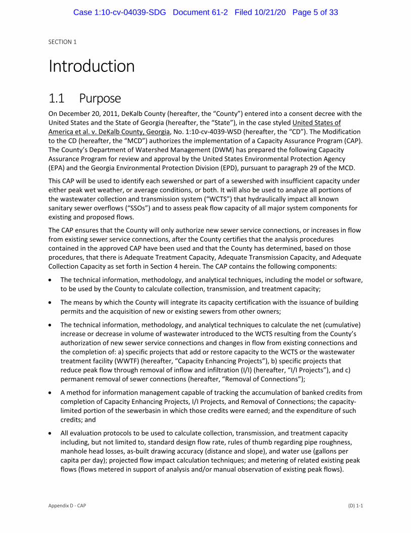
1.1 Purpose On December 20, 2011, DeKalb County (hereafter, the “County”) entered into a consent decree with the United States and the State of Georgia (hereafter, the “State”), in the case styled United States of America et al. v. DeKalb County, Georgia, No. 1:10-cv-4039-WSD (hereafter, the “CD”). The Modification to the CD (hereafter, the “MCD”) authorizes the implementation of a Capacity Assurance Program (CAP). The County’s Department of Watershed Management (DWM) has prepared the following Capacity Assurance Program for review and approval by the United States Environmental Protection Agency (EPA) and the Georgia Environmental Protection Division (EPD), pursuant to paragraph 29 of the MCD.
This CAP will be used to identify each sewershed or part of a sewershed with insufficient capacity under either peak wet weather, or average conditions, or both. It will also be used to analyze all portions of the wastewater collection and transmission system (“WCTS”) that hydraulically impact all known sanitary sewer overflows (“SSOs”) and to assess peak flow capacity of all major system components for existing and proposed flows.
The CAP ensures that the County will only authorize new sewer service connections, or increases in flow from existing sewer service connections, after the County certifies that the analysis procedures contained in the approved CAP have been used and that the County has determined, based on those procedures, that there is Adequate Treatment Capacity, Adequate Transmission Capacity, and Adequate Collection Capacity as set forth in Section 4 herein. The CAP contains the following components:
The technical information, methodology, and analytical techniques, including the model or software, to be used by the County to calculate collection, transmission, and treatment capacity;
The means by which the County will integrate its capacity certification with the issuance of building permits and the acquisition of new or existing sewers from other owners;
The technical information, methodology, and analytical techniques to calculate the net (cumulative) increase or decrease in volume of wastewater introduced to the WCTS resulting from the County’s authorization of new sewer service connections and changes in flow from existing connections and the completion of: a) specific projects that add or restore capacity to the WCTS or the wastewater treatment facility (WWTF) (hereafter, “Capacity Enhancing Projects”), b) specific projects that reduce peak flow through removal of inflow and infiltration (I/I) (hereafter, “I/I Projects”), and c) permanent removal of sewer connections (hereafter, “Removal of Connections”);
A method for information management capable of tracking the accumulation of banked credits from completion of Capacity Enhancing Projects, I/I Projects, and Removal of Connections; the capacity-limited portion of the sewerbasin in which those credits were earned; and the expenditure of such credits; and
All evaluation protocols to be used to calculate collection, transmission, and treatment capacity including, but not limited to, standard design flow rate, rules of thumb regarding pipe roughness, manhole head losses, as-built drawing accuracy (distance and slope), and water use (gallons per capita per day); projected flow impact calculation techniques; and metering of related existing peak flows (flows metered in support of analysis and/or manual observation of existing peak flows).
Case 1:10-cv-04039-SDG Document 61-2 Filed 10/21/20 Page 5 of 33

SECTION 1
Appendix D - CAP (D) 1-2
1.2 Authority The County’s legal authority for the development and implementation of this CAP is:
The U.S. Clean Water Act
Georgia Water Quality Control Act
The previously discussed modified CD
1.3 Related DeKalb County Documents The County has several documents that are critical to and referenced throughout this CAP. Table 1-1 lists the documents and their locations.
Table 1-1. CAP Related Documents
Document Location
DeKalb County DWM Water and Sewer Design
Standards Manual DeKalb County DWM website
Priority Areas Sewer Assessment and
Rehabilitation Program DeKalb County DWM website
System-Wide Flow & Rainfall Monitoring
Program DeKalb County DWM website
Sewer Mapping Program DeKalb County DWM website
System-Wide Hydraulic Model DeKalb County DWM website
Infrastructure Acquisitions Program DeKalb County DWM website
Sub-Model Reports DeKalb County DWM website
1.4 Implementation Schedule The following is required prior to use of the Fully Developed Dynamic Model for approval of new sewer connections within each Sub-Model Area:
Completion of submission of Sub-Model to the EPA/EPD for review and comment
Written approval from the EPA/EPD of the Sub-Model Report
Entry of the MCD in Federal Court
Until all of the criteria listed above are completed, the County shall continue to use in that area its existing hydraulic models to evaluate, and where appropriate certify, adequate capacity for all new sewer service connections or increases in flow from existing sewer service connections pursuant to the original provisions of Paragraph 28(g) of the CD.
Case 1:10-cv-04039-SDG Document 61-2 Filed 10/21/20 Page 6 of 33
SECTION 2
Appendix D - CAP (D) 2-1
Overview
2.1 Description of Wastewater Collection and Transmission System
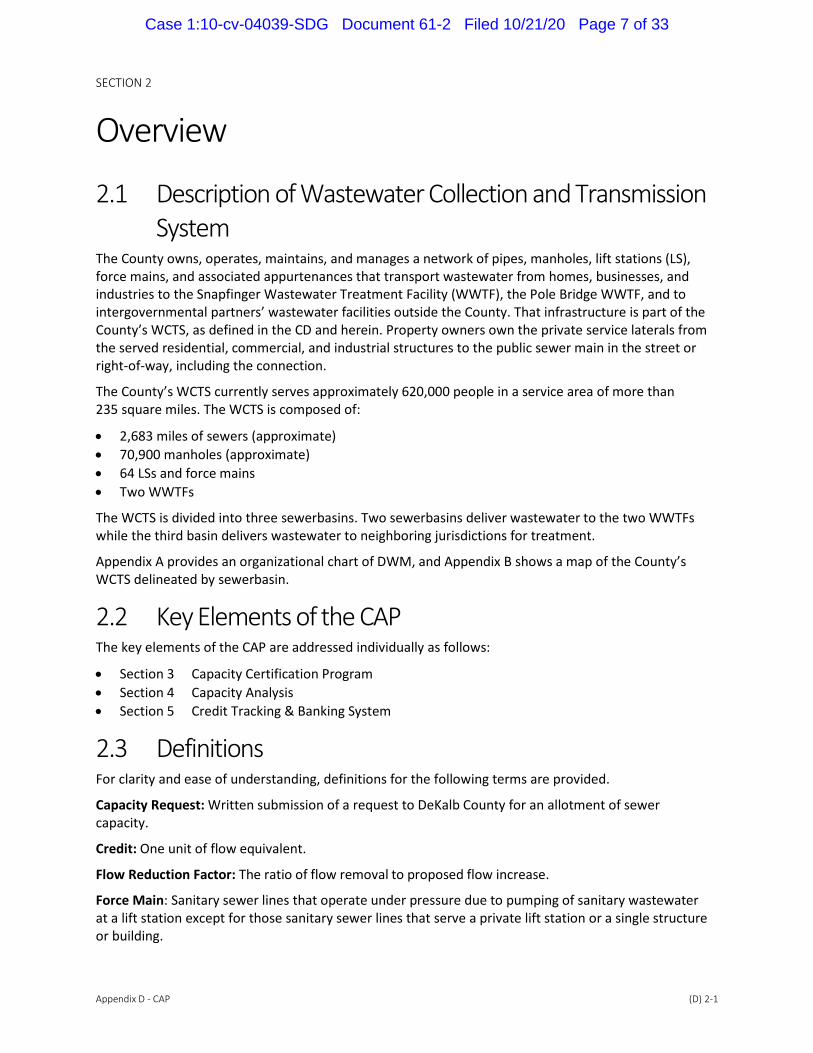
The County owns, operates, maintains, and manages a network of pipes, manholes, lift stations (LS), force mains, and associated appurtenances that transport wastewater from homes, businesses, and industries to the Snapfinger Wastewater Treatment Facility (WWTF), the Pole Bridge WWTF, and to intergovernmental partners’ wastewater facilities outside the County. That infrastructure is part of the County’s WCTS, as defined in the CD and herein. Property owners own the private service laterals from the served residential, commercial, and industrial structures to the public sewer main in the street or right-of-way, including the connection.
The County’s WCTS currently serves approximately 620,000 people in a service area of more than 235 square miles. The WCTS is composed of:
2,683 miles of sewers (approximate)
70,900 manholes (approximate)
64 LSs and force mains
Two WWTFs
The WCTS is divided into three sewerbasins. Two sewerbasins deliver wastewater to the two WWTFs while the third basin delivers wastewater to neighboring jurisdictions for treatment.
Appendix A provides an organizational chart of DWM, and Appendix B shows a map of the County’s WCTS delineated by sewerbasin.
2.2 Key Elements of the CAP The key elements of the CAP are addressed individually as follows:
Section 3 Capacity Certification Program
Section 4 Capacity Analysis
Section 5 Credit Tracking & Banking System
2.3 Definitions For clarity and ease of understanding, definitions for the following terms are provided.
Capacity Request: Written submission of a request to DeKalb County for an allotment of sewer capacity.
Credit: One unit of flow equivalent.
Flow Reduction Factor: The ratio of flow removal to proposed flow increase.
Force Main: Sanitary sewer lines that operate under pressure due to pumping of sanitary wastewater at a lift station except for those sanitary sewer lines that serve a private lift station or a single structure or building.
Case 1:10-cv-04039-SDG Document 61-2 Filed 10/21/20 Page 7 of 33

SECTION 2
Appendix D - CAP (D) 2-2
Fully Developed Dynamic Model: A dynamic hydraulic model officially authorized for use by the DeKalb County after it is certified by a professional engineer on the County’s behalf as meeting the technical criteria and functions specified in the MCD and the Sub-Model Reports, and is supported by complete documentation of model development, calibration, validation/verification, sensitivity analysis, appropriate flow conditions, and operation, use, and maintenance procedures.
Gravity Sewer Line: A pipe that receives, contains, and conveys wastewater not normally under pressure, or head, but is intended to flow unassisted under the influence of gravity.
Illicit Connection: Any pipe, open channel, drain, or conveyance, whether on the surface or subsurface, that allows any direct or indirect non-stormwater discharge to the DeKalb County Municipal Separate Storm Sewer System (MS4) including, but not limited to any conveyances which allow any non-stormwater discharge including sewage, process wastewater, and wash water to enter the MS4, regardless of whether such pipe, open channel, drain, or conveyance has been previously allowed, permitted, or approved by a federal, state, or local law enforcement agency.
Infiltration: Defined by 40 CFR § 35.2005(b) (20) shall mean water other than wastewater that enters a WCTS (including sewer service connections and foundation drains) from the ground through such means as defective pipes, pipe joints, connections, or manholes.
Inflow: Defined by 40 CFR § 35.2005(b)(21) shall mean water other than wastewater that enters a sanitary sewer system (including sewer service connections) from source such as, but not limited to, roof leaders, cellar drains, yard drains, area drains, drains from springs and swampy areas, manhole covers, cross connections between storm sewers and sanitary sewers, catch basins, cooling towers, storm water, surface runoff, street wash waters, or drainage.
NPDES Permits: The most recently issued National Pollutant Discharge Elimination System Permits issued to the County for the Pole Bridge WWTF and the Snapfinger WWTF.
1-Hour Peak Flow: Per Paragraph 29 of the MCD, the 1-hour peak flow is the greatest flow in a sewer averaged for a 60-minute period at a specific location expected to occur as a result of a representative 2-year, 24-hour storm event.
Overflow: A release of wastewater from the WCTS, or from an WWTF, caused by problems in the WCTS, that does not reach waters of the United States or the state.
Priority Areas: Portions of the WCTS within Initial or Additional Priority Areas as defined and delineated in the July 2015 Priority Areas Sewer Assessment and Rehabilitation Program Report as referenced in Table 1-1 herein.
Priority Fix List: A listing of repeat SSO locations as defined in Section VI, Paragraph 35(j) of the Consent Decree as revised per the MCD.
Private Lateral: That portion of a sanitary sewer conveyance pipe, including that portion in the public right of way, that extends from the wastewater main to the single-family, multi-family, apartment or other dwelling unit or commercial or industrial structure to which wastewater service is or has been provided.
Sanitary Sewer Overflow or SSO: Spills, overflows, and building backups.
Sewershed: The subdivisions of the County’s WCTS containing sewers that are primarily hydraulically linked as identified in Appendix A of the Consent Decree.
Spill: A discharge of wastewater from the WCTS, or from an WWTF caused by problems in the WCTS, which reaches waters of the United States or the State, including a prohibited bypass, but not including other discharges from a point source that is specified in the NPDES permits.
Case 1:10-cv-04039-SDG Document 61-2 Filed 10/21/20 Page 8 of 33

SECTION 2
Appendix D - CAP (D) 2-3
2-year, 24-hour Flow Condition: The peak hourly flow from a rainfall event 24 hours in duration that has a 50 percent probability of occurring in any one year.
Wastewater Collection and Transmission Systems: All wastewater collection and transmission systems, including all pipes, lift stations, force mains, gravity sewer lines, manholes and appurtenances thereto, which are owned or operated by the County, except for those portions of a system or systems for which another entity is legally responsible for maintenance.
Wastewater Treatment Facility: Devices or systems used in the storage, treatment, recycling, and reclamation of municipal sewage. This definition includes the following facilities owned, managed, operated, and maintained by the County: the Pole Bridge WWTF and the Snapfinger WWTF.
Case 1:10-cv-04039-SDG Document 61-2 Filed 10/21/20 Page 9 of 33

SECTION 3
Appendix D - CAP (D) 3-1
Capacity Evaluation Program The CAP will analyze portions of the WCTS that are indicative of being hydraulically limited including: 1) identifying each sewerbasin or part of a sewerbasin with temporarily insufficient capacity under either 1-hour peak flows, or average conditions, or both; 2) analyzing the portions of the WCTS that hydrau-lically impact known SSOs; and 3) assessing the peak or average flow capacity of all major system components for existing and proposed flows.
The CAP provides a process for the County to determine whether there is adequate treatment, trans-mission, and collection capacity before it authorizes a new sewer service connection in the WCTS, or additional flow from an existing sewer service connection in the WCTS, as set forth in this section.
Appendix C provides a flowchart that provides an overview of the capacity evaluation process. The steps are further described throughout this section and the following sections of this document.
Certifications will be made by a professional engineer registered in the state of Georgia and reviewed and approved by an authorized representative of the County.
3.1 Capacity Request Submittal An entity requesting connection to the WCTS, or an increase in flow, will be required to submit a Sewer Capacity Evaluation Request Form. The request will be submitted through the Planning & Development Division of DWM at the beginning stages of development. Appendix D provides an example Sewer Capacity Evaluation Request Form.
3.1.1 Flow Estimates for Additional Flows Flow estimates shall be provided by the requestor and included in the Sewer Capacity Evaluation Request Form. Estimated flows from new sewer service connections or estimated increases in flow from existing sewer service connections shall be based upon the latest approved table of standard design flow rates which are included as an attachment to the County’s Sewer Capacity Evaluation Request Form. Alternative flow contribution rates shall be considered with supporting information.
3.1.2 Other Required Information Other information on the Sewer Capacity Evaluation Request Form shall include the following:
Location Address
Intended Tie-In Manhole
Project Name
Type of Development
Land Lot and Parcel ID
County District
Developer Contact Information
Engineering Firm Contact Information
Geographic Information System (GIS) Site Plan
Proposed Utility Plan (if available)
Case 1:10-cv-04039-SDG Document 61-2 Filed 10/21/20 Page 10 of 33

SECTION 3
Appendix D - CAP (D) 3-2
Within 60 days of entry of the MCD, the County shall establish a list with detailed information of authorized new connections to the sewer system from date of entry of the MCD and increases in flow from existing connections from which the flows have not yet been introduced into the WCTS. The information shall include the address, average daily flow, peak flow, sewershed, Wastewater Treatment Facility (WWTF), date authorized, and estimated month/quarter when flow will begin.
3.2 Capacity Analysis Evaluation DWM will perform the capacity analysis with the provided information from the Sewer Capacity Evaluation Request Form. The detailed process of performing this analysis is described in Section 4.
3.3 Issuance of Certifications Upon approval of new connection or additional flow request, the County will provide the requestor with a completed Sewer Capacity Letter stating approval for connection. The date will be documented and updated in the County’s tracking system.
3.4 Minor Sewer Connections Minor sewer connections are defined in this CAP as connections in which the average daily flow is not to exceed 2,500 gpd. For minor sewer connections, the County may elect to perform a monthly capacity analysis for each sewershed or part of a sewershed to verify that the sewershed or part of a sewershed has adequate capacity as defined in Section 4 for all sewer connections approved in the previous month as well as for additional flows generated by all anticipated minor sewer connections in the subsequent month. The County shall evaluate proposed new minor connections on a monthly basis to certify adequate capacity for the total anticipated one-hour peak flow from all minor connections and shall include this anticipated one-hour peak flow in all capacity evaluations. The County will validate the prior month’s flow estimate for anticipated minor sewer connections at the beginning of the following month and adjust capacity evaluations accordingly. If the County uses the credit bank described in Section 5 to approve any minor sewer connections, the subtraction from the credit bank shall not result in a negative balance of banking credits.
3.5 Capacity Approval In Lieu of Certification Process The County may authorize new sewer service connections or additional flow from an existing connection even if it cannot satisfy the requirements of Section 3.2 and 3.3, provided the County complies with the following provisions and a Professional Engineer certifies and stamps, prior to the authorization, that all applicable provisions are satisfied:
The County is in substantial compliance with the Consent Decree as modified by the MCD;
The sewer lines that will convey the proposed additional flow from new or existing sewer service connections have not experienced dry weather SSOs resulting from inadequate capacity within the previous 12 months or the County has certified the causes of any dry weather SSOs due to inadequate capacity have been eliminated;
The County has identified the sewer line segment(s), LS(s), and/or wastewater treatment systems that do not meet the conditions for certification of adequate treatment, transmission, or collection capacity; and
Case 1:10-cv-04039-SDG Document 61-2 Filed 10/21/20 Page 11 of 33

SECTION 3
Appendix D - CAP (D) 3-3
The County may authorize a new sewer service connection or increase in flow to an existing connection prior to the completion of a necessary added capacity or peak flow reduction project, but the project must be completed prior to the time that the new sewer service connection or flow increase is introduced to the WCTS (the credit tracking system is described in Section 5)
3.5.1 Essential Services Notwithstanding the provisions of Section 3.2 and 3.3, the County may authorize a new sewer service connection, or additional flow from an existing sewer service connection, even if it cannot certify that it has adequate treatment, transmission, or collection capacity, for the following:
health care facilities, public safety facilities, public schools, and, subject to EPA/EPD review and approval, government and other facilities
cases where a pollution or health or safety condition exists, as determined by the DeKalb County Health Department or its regulatory successor, as the result of a discharge of untreated wastewater from an onsite septic system or other discharge point
For new service connections, or additions to flow from an existing connection, the County will make the appropriate subtraction to the balance in the credit bank described in Section 5. The subtraction may result in a negative balance in the credit bank if sufficient credits are not available to offset the flow increase.
3.5.2 Existing Illicit Connections Notwithstanding the other provisions of Section 3, the County may authorize a new sewer service connection, or additional flow from an existing sewer service connection, even if it cannot certify that it has adequate treatment, transmission, or collection capacity for any illicit connections or discharge of wastewater to the stormwater system or to waters of the state. For such new service connections or additions to flow from an existing connection the County will make a subtraction from the balance in the credit bank described in Section 5. The subtraction may result in a negative balance in the credit bank if sufficient credits are not available to offset the flow increase.
3.6 Temporary Service Lateral Suspensions The County may reconnect, without certifying Adequate Capacity, any connection that is temporarily suspended from the WCTS in order to complete work to replace or repair the service lateral. The term “temporarily suspended” as it applies to this section refers only to service lateral connections that are suspended while work is actively pursued to replace or repair the service lateral.
3.7 Issuance of Land Development or Building Permits The County and City ordinances stipulate that a land development permit is required if any part of the development involves land disturbance, as well as a building permit is required for a new development and for redevelopment of an existing property. The permitting process requires a certification that the WCTS has adequate capacity or an approval in lieu of the certification as described in this Section in order to accept the development’s new sewer service connection or additional flow to an existing sewer service connection.
Case 1:10-cv-04039-SDG Document 61-2 Filed 10/21/20 Page 12 of 33
SECTION 4
Appendix D - CAP (D) 4-1
Capacity Analysis
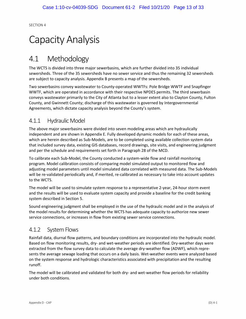
4.1 Methodology The WCTS is divided into three major sewerbasins, which are further divided into 35 individual sewersheds. Three of the 35 sewersheds have no sewer service and thus the remaining 32 sewersheds are subject to capacity analysis. Appendix B presents a map of the sewersheds.
Two sewerbasins convey wastewater to County-operated WWTFs: Pole Bridge WWTF and Snapfinger WWTF, which are operated in accordance with their respective NPDES permits. The third sewerbasin conveys wastewater primarily to the City of Atlanta but to a lesser extent also to Clayton County, Fulton County, and Gwinnett County; discharge of this wastewater is governed by Intergovernmental Agreements, which dictate capacity analysis beyond the County’s system.
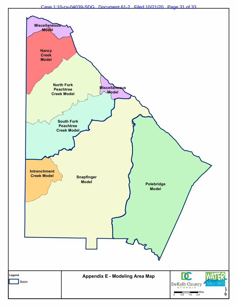
4.1.1 Hydraulic Model The above major sewerbasins were divided into seven modeling areas which are hydraulically independent and are shown in Appendix E. Fully developed dynamic models for each of these areas, which are herein described as Sub-Models, are to be completed using available collection system data that included survey data, existing GIS databases, record drawings, site visits, and engineering judgment and per the schedule and requirements set forth in Paragraph 28 of the MCD.
To calibrate each Sub-Model, the County conducted a system-wide flow and rainfall monitoring program. Model calibration consists of comparing model simulated output to monitored flow and adjusting model parameters until model simulated data correlated with measured data. The Sub-Models will be re-validated periodically and, if merited, re-calibrated as necessary to take into account updates to the WCTS.
The model will be used to simulate system response to a representative 2-year, 24-hour storm event and the results will be used to evaluate system capacity and provide a baseline for the credit banking system described in Section 5.
Sound engineering judgment shall be employed in the use of the hydraulic model and in the analysis of the model results for determining whether the WCTS has adequate capacity to authorize new sewer service connections, or increases in flow from existing sewer service connections.
4.1.2 System Flows Rainfall data, diurnal flow patterns, and boundary conditions are incorporated into the hydraulic model. Based on flow monitoring results, dry- and wet-weather periods are identified. Dry-weather days were extracted from the flow survey data to calculate the average dry-weather flow (ADWF), which repre-sents the average sewage loading that occurs on a daily basis. Wet-weather events were analyzed based on the system response and hydrologic characteristics associated with precipitation and the resulting runoff.
The model will be calibrated and validated for both dry- and wet-weather flow periods for reliability under both conditions.
Case 1:10-cv-04039-SDG Document 61-2 Filed 10/21/20 Page 13 of 33

SECTION 4
Appendix D - CAP (D) 4-2
4.2 Collection Capacity Analysis
4.2.1 Procedure Proposed increases in flow and additional connections to the existing WCTS will be entered into the hydraulic model to simulate the proposed flow scenario. A hydraulic model analysis will be performed using the InfoWorks ICM software for the design storm, and the hydraulic gradeline (HGL) will be developed. The HGL will be compared to target system capacity requirements to determine if the increase in flow will violate capacity assessment criteria. The model will predict locations of capacity deficits and the County can then address those areas. The analyses will include documentation and supporting information regarding model outputs and any necessary potential variations as well as consider real-world conditions and engineering judgment.
4.2.2 Collection Capacity Definition Adequate collection capacity will require that every gravity sewer line in the WCTS, through which the proposed additional flow from new or existing connections would pass, has the capacity to carry the following flows without causing a surcharge condition. The analyses shall confirm that the following flow conditions do not cause surcharge:
existing 1-hour peak flow passing though the gravity sewer line
the addition to the existing 1-hour peak flow from the proposed connection
the addition to the existing 1-hour peak flow predicted to occur from all other authorized sewer service connections that have not begun to discharge into the WCTS
For the purposes of this paragraph, a surcharge condition shall mean the condition that exists when the supply of wastewater resulting from the 1-hour peak flow is greater than the capacity of the pipes to carry it and the surface of the wastewater in manholes rises to an elevation greater than the top of the pipe. However, if the County has identified sewer line segments which have been specifically designed and constructed to operate under surcharge conditions and has identified the level of surcharge for those segments, the identified level of surcharge shall be used. Notwithstanding the immediately preceding sentence, any rise in elevation above the top of the pipe shall be considered a surcharge condition if the manhole has experienced a capacity-related SSO since December 20, 2017 (excluding those SSOs caused by severe natural conditions such as hurricanes, tornados, widespread flooding, earthquakes, and other similar natural conditions) unless the County can certify that the cause of the SSO has been corrected through improvements to the WCTS.
4.3 Transmission Capacity Analysis
4.3.1 Procedure The design hydraulic capacities of each LS in the system are represented in the hydraulic model. Con-firmation of the effective LS capacities are determined using flow monitoring data or performed through wet well drawdown tests. Appendix F shows sewer LS and force main locations. The analyses will include documentation and supporting information regarding model outputs and potential variations or adjustments as necessary and consider real-world conditions and engineering judgment.
Case 1:10-cv-04039-SDG Document 61-2 Filed 10/21/20 Page 14 of 33

SECTION 4
Appendix D - CAP (D) 4-3
4.3.2 Transmission Capacity Definition Adequate transmission capacity means that each LS through which the proposed additional flow from new or existing sewer service connections would pass to the WWTF has the capacity to transmit, with its largest pump out of service, the following flows:
existing 1-hour peak flow passing through the LS
the addition to the existing 1-hour peak flow predicted to occur from the proposed connection
the addition to the existing 1-hour peak flow predicted to occur from all other authorized sewer service connections that have not begun to discharge into the WCTS
4.4 Treatment Capacity Analysis
4.4.1 Procedure The Pole Bridge Basin flows to the Pole Bridge WWTF and the Snapfinger Basin drains to the Snapfinger WWTF. Treatment capacity will be analyzed to ensure that both facilities operate in accordance to their respective NPDES permits.
4.4.2 Treatment Capacity Definition Adequate treatment capacity means that, at the time the WWTF receives the flow from a proposed sewer service connection(s) or increased flow from an existing sewer service connection(s), when combined with the flow predicted to occur from all other authorized sewer service connections (including those that have not begun to discharge into the WCTS), the WWTF will not be in “non-compliance” for quarterly reporting, as defined in 40 CFR Part 123.45, Appendix A.
4.5 New Connection Conditions
4.5.1 Procedure The County may also authorize new sewer service connections or increases in flow from existing connections where the New Connection Conditions defined below are satisfied and where adequate transmission capacity and adequate treatment capacity is available as determined per Sections 4.3 and 4.4 above.
4.5.2 New Connection Conditions Definition New Connection Conditions are defined by the following:
The dynamic hydraulic model does not predict any overflows from the new sewer service connections and/or increases in flow from the existing sewer service connections
The dynamic hydraulic model does not predict that, after adding the new sewer service connections and/or increases in flow from the existing sewer service connections to all existing and authorized sewer connections, the wastewater in any manhole from the 1-hour peak flow resulting from a representative 2-year, 24-hour storm event will rise to an elevation within two (2) feet of ground surface at any location in the WCTS through which the proposed additional flows from the new or
Case 1:10-cv-04039-SDG Document 61-2 Filed 10/21/20 Page 15 of 33

SECTION 4
Appendix D - CAP (D) 4-4
existing connection would pass. However, for manholes within 350 feet of the entrance to or exit from aerial crossings (at locations including creeks, dry beds, stormwater ditches and conveyances, and intermittent and ephemeral streams) with less than two (2) feet of ground cover over their connecting pipes, the wastewater predicted as described above shall not rise to an elevation of within two (2) feet of the manhole rim.
All capacity-related locations on the Priority Fix List downstream of the proposed new sewer service connection or proposed increase in flows from an existing sewer service connection have been adequately rehabilitated, relieved, fixed, or otherwise addressed (“Adequately Fixed”) and either:
o At least one (1) year has passed since completion of such Adequate Fix without a capacity-related SSO occurring at any such location (excluding those SSOs caused by severe natural conditions such as hurricanes, tornados, widespread flooding, earthquakes, and other similar natural conditions)
o Or, each such location has experienced a 2-year, 24-hour storm event (or a 24-hour storm event of greater size) without a capacity-related SSO
Any location that has experienced a capacity-related SSO (excluding those SSOs caused by severe natural conditions such as hurricanes, tornados, widespread flooding, earthquakes, and other similar natural conditions) within the previous two (2) years downstream of the proposed new sewer service connection or proposed increase in flow from an existing sewer service connection has been adequately rehabilitated, relieved, fixed, or otherwise addressed (“Adequately Fixed”) and either:
o At least one (1) year has passed since completion of such Adequate Fix without a capacity-related SSO occurring at any such location (excluding those SSOs caused by severe natural conditions such as hurricanes, tornados, widespread flooding, earthquakes, and other similar natural conditions)
o Or, each such location has experienced a 2-year, 24-hour storm event (or a 24-hour storm event of greater size) without a capacity-related SSO
Case 1:10-cv-04039-SDG Document 61-2 Filed 10/21/20 Page 16 of 33
SECTION 5
Appendix D - CAP (D) 5-1
Banking Credit SystemAs part of the Capacity Approval in Lieu of Certification Process described in Section 3.5, the County may use a “banking credit system” for the sewer line segment(s), LS(s), and/or WWTF for which the County is unable to certify adequate capacity.
The addition of sewer capacity and/or reduction in 1-hour peak flows from Capacity Enhancement Projects which are completed and in-use may be accumulated in the form of credits in the banking credit system in accordance with this document. The County may earn banking credits for phased Capacity Enhancement Projects, where permanent capacity is added to the WCTS from completion of a phase of such projects. For example, if a project has 10 phases, the County may earn banking credits upon completion of the first phase to the extent that permanent capacity is added to the WCTS based on that phase of the overall project. Credits from the banking credit system may then be used for authorization of new sewer service connections or increases in flow from existing connections within the hydraulically independent Sub-Model area where the project that earned the credits occurred.
The banking credit system may only be used after the County certifies to the EPA and EPD that the Information Management System described in Section 5.1 below is operational. Capacity Enhancement Projects completed after entry of the MCD may earn credits in the credit banking system as well as those Capacity Enhancement Projects completed after April 29, 2019.
5.1 Capacity Assurance Information Management System The Capacity Assurance Program will utilize an information management system comprised of the County’s CityWorks Computerized Maintenance Management System, the GIS, and other software to track and report sewer capacity request information. Additionally, the information management system will manage the recording and reporting of earned banking credits and the subsequent expenditure of those credits.
As part of the documentation to the EPA and EPD certifying that the information management system is operational, the County will provide a representative report of the data recorded from sewer capacity requests and from the banking credit system for EPA and EPD review.
As the County implements the information management system, the County may develop additional software solutions to further streamline and automate recording and reporting of CAP information.
5.2 Deposits Capacity improvement documentation will be completed to deposit credits from projects as described in this section into the banking credit system. The guidelines presented in Section 5.3 shall be used along with engineering judgment when depositing credits into the system.
Within 12 months following approval of the CAP, and annually thereafter as necessary, the County shall perform a review of specific Capacity Enhancement Projects to determine if actual added capacity and peak flow reductions are in line with the County’s original estimation for such projects. The County will use the results of this review to adjust future estimates as necessary.
Case 1:10-cv-04039-SDG Document 61-2 Filed 10/21/20 Page 17 of 33
SECTION 5
Appendix D - CAP (D) 5-2
5.3 Capacity Enhancing Projects
5.3.1 Offline Storage Offline storage projects will add capacity credits equal to the volume of the storage constructed unless the project is located within a Priority Area in which case the credit shall be equal to the volume of the storage constructed divided by a factor of 2.
5.3.2 Removal of Connections Removal of connections may add capacity credits equal to the estimated flow that the connections previously produced unless the project is located within a Priority Area in which case the credit shall be equal to the estimated flow that the connections previously produced divided by a factor of 2.
5.3.3 Gravity Sewer Line Improvements Gravity sewer line improvements will add capacity credits equal to the added capacity resulting from such projects divided by a factor of 3 unless the improvements are located within a Priority Area in which case the credit calculated shall be divided by a factor of 4. See Section 5.3.7.
5.3.4 LS Improvements Lift Station (“LS”) improvement projects will add capacity credits equal to the volume of additional storage in the wet well. If the LS has been a restriction, then the County will analyze the increased LS capacity prior to including any additional system credits. If the LS improvement project is located within a Priority Area, the capacity credit calculated per above shall be divided by a factor of 2.
5.3.5 Treatment Facility Improvements Treatment facility improvement projects will add capacity credits equal to the volume of additional storage available in the facility and/or equal to the additional discharged flow that meets the require-ments of the current NPDES permit.
5.3.6 I/I Reduction Projects The estimated flow reductions resulting from completion of I/I reduction projects will add capacity credits equal to the estimated amount of the flow reduction divided by a factor of 3 unless the project is located within a Priority Area in which case the estimated amount of flow reduction shall be divided by a factor of 4. See Section 5.3.7.
5.3.6.1 Rehabilitation of Gravity Sewers
The estimated rate of flow reduction will be determined based on Table 5-1 or actual flow data and/or engineering analysis dependent on the defects observed and the actual rehabilitation work to be completed.
Case 1:10-cv-04039-SDG Document 61-2 Filed 10/21/20 Page 18 of 33

SECTION 5
Appendix D - CAP (D) 5-3
Table 5-1. Estimated Peak Flow Reductions for Gravity Sewer Rehabilitation
Rehabilitation MethodEarned Base Credits per inch-diameter-
mile rehabilitated
Riparian Zone – Piping is within 50 feet horizontally of
a stream or water body.
34,000 gpd
Non-riparian Area – Piping is not located within the
Riparian Zone.
60 gpd
5.3.6.2 Storm Drain and Downspout Removal and Cleanout Cap Replacement
Depending on the location and size of the drain, the flow estimation can be either calculated using standard engineering practices or it can be estimated using the values from Table 5-2.
Table 5-2. Estimated Peak Flow Reductions for Storm Drain and Downspout Removal
Drain Earned Base Credits per Drain Removed
Storm Drain <10” diameter 7,000 gpd
Storm Drain >10” diameter To be calculated
Downspout 5,000 gpd
Cleanout Cap Replacement 250 gpd
5.3.6.3 Foundation Drain Pump Removal
Disconnecting foundation drain sump pumps from the WCTS is estimated to reduce peak flows by approximately 4,000 gpd per sump pump removed.
5.3.6.4 Replacement of Vented Manhole Lids
Table 5-3 lists the base credits for vented manhole lid replacement prior to the factor reductions.
Table 5-3. Estimated Peak Flow Reductions for Vented Manhole Lid Replacement
Manhole Location Earned Base Credits
Riparian Zone – Manhole is within 50 feet horizontally of a stream or water
body. Manhole is assumed to be subject to 1 inch of inundation if located within
the riparian zone.
40,000 gpd
Paved Area – Manhole is located in a paved, curbed area at a distance from the
curb that is less than one-fourth of the total roadway width. Manhole is
assumed to be subject to one-eighth of an inch inundation if located within the
paved area.
9,000 gpd
Non-riparian Area – Manhole does not fall into one of the other categories
listed above but are flush with the ground surface is assumed to be subject to
“splash” conditions.
2,500 gpd
5.3.6.5 Repair of Manhole Defects
Table 5-4 provides the base credits for manhole defect repair prior to the factor reductions.
Case 1:10-cv-04039-SDG Document 61-2 Filed 10/21/20 Page 19 of 33

SECTION 5
Appendix D - CAP (D) 5-4
Table 5-4. Earned Base Credits for Repair of Manhole Defects (in gpd)
Manhole
Component
Minor I/I Moderate I/I Heavy I/I Severe I/I
R P N R P N R P N R P N
Frame Seal 864 78 328 1,728 156 656 3,456 311 1,313 6,912 622 2,626
Chimney 864 78 328 1,728 156 656 3,456 311 1,313 6,912 622 2,626
Cone 864 78 328 1,728 156 656 3,456 311 1,313 6,912 622 2,626
Wall 432 39 164 864 75 328 1,728 156 656 3,456 311 1,313
Pipe Seal 432 39 164 864 75 328 1,728 156 656 3,456 311 1,313
Bench 432 39 164 864 75 328 1,728 156 656 3,456 311 1,313
Channel 432 39 164 864 75 328 1,728 156 656 3,456 311 1,313
Source: Adapted from Table 4-1 of The American Society of Civil Engineers, Manual of Practice No. 92 Notes: R = Riparian P = Paved N = Non-riparian
5.3.7 Conditional Reduction in Banking Credit Ratios Used for Gravity Sewer Line Improvement and I/I Reduction Projects
Upon the County’s timely completion of its obligation to adequately fix 50% of the Priority Fix List locations identified in Appendix F to the MCD (within two (2) years from the Date of Entry of the MCD), the banking credit ratios provided in Sections 5.3.3 and 5.3.6 (above) will be adjusted for gravity sewer line improvement projects and for I/I reduction projects. The banking credit ratios will be adjusted, as follows:
Gravity sewer line improvements (Section 5.3.3 above) will add capacity credits equal to the added capacity resulting from such projects divided by a factor of 2 unless the improvements are located within a Priority Area in which case the credit calculated shall be divided by a factor of 3.
The estimated flow reductions resulting from completion of I/I reduction projects (Section 5.3.6 above) will add capacity credits equal to the estimated amount of the flow reduction divided by a factor of 2 unless the project is located within a Priority Area in which case the estimated amount of flow reduction shall be divided by a factor of 3.
In the event that the County fails to meet any deadline for adequately fixing any Priority Fix List location, as provided in Paragraph 35(j) of the MCD, the banking credit ratios for gravity sewer line improvement projects and for I/I reduction projects will revert to the ratios provided for in Sections 5.3.3 and 5.3.6.
5.4 Capacity Approvals In Lieu of Capacity Certification For new or additional flow contributions from sewer service connections that have been authorized in lieu of capacity certification, capacity credits equal to the estimated amount of the proposed new or additional flow will be withdrawn from the credit banking system balance at the time of authorization. The Capacity Approval In Lieu of Capacity Certification process is further described in Section 3.5.
Case 1:10-cv-04039-SDG Document 61-2 Filed 10/21/20 Page 20 of 33

SECTION 6
Appendix D - CAP (D) 6-1
References American Petroleum Institute (API). 2009. Piping Inspection Code: In-service Inspection, Rating, Repair, and Alteration of Piping Systems (API 570). February.
American Society of Civil Engineers (ASCE). 2009. Manual of Practice No. 92 Manhole Inspection and Rehabilitation. August 12.
DeKalb County Department of Watershed Management. 2017. Design Standards Manual: Potable Water Main, Gravity Sanitary Sewer, Sanitary Sewer Pumping Station and Force Main Design Standards.
Hughes, John. 2009. Manhole Inspection and Rehabilitation (ASCE Manuals and Reports on Engineering Practices No. 92). July 1.
Meyer, Jack. M. Neenah Foundry Company. 1976. A Report on Inflow of Surface Water Through Manhole Covers.
National Association of Corrosion Engineers (NACE). 2010. Pipeline External Corrosion Direct Assessment Methodology (ANSI/NACE SP0502). June 24.
National Association of Sewer Service Companies (NASSCO). 2018. Pipeline Assessment & Certification Program (PACP) v7.0.3.
Wastewater Committee of the Great Lakes--Upper Mississippi River Board of State and Provincial Public Health and Environmental Managers. 2014. Recommended Standards for Wastewater Facilities (Ten States Standards).
Water Environment Federation (WEF). 1993. Design of Wastewater and Stormwater Pumping Stations (Manual of Practice FD-4). January.
Water Environment Federation (WEF). 2013. Guide for Municipal Wet Weather Strategies. July 22.
Water Environment Research Foundation (WERF). 2010. Inspection Guidelines for Wastewater Force Mains 04-CTS-6URa.
Case 1:10-cv-04039-SDG Document 61-2 Filed 10/21/20 Page 21 of 33

Appendix A Department Watershed Management
Organizational Chart
Case 1:10-cv-04039-SDG Document 61-2 Filed 10/21/20 Page 22 of 33

DCOO/Infrastructure
Director
ENGINEERING AND CONSTRUCTION MANAGEMENT
FINANCE/ADMINISTRATION
ADMINISTRATIVE SERVICES
OPERATIONS COMPLIANCE
CIP
Construction Management
Engineering Design
Budget
Accounting
IT
Procurement
Human Resources
Employee Training
Treatment Plants
Construction and Maintenance
Customer Response Dispatch
Meter & Field Services
Facilities/Fleet
FOG
Industrial Pretreatment
Laboratories
ModelingFlow and Rainfall
Monitoring
Infrastructure Acquisitions
Program
CMOM
GIS
DEPARTMENT OF WATERSHED MANAGEMENTO R G A N I Z AT I O N C H A R T
Case 1:10-cv-04039-SDG Document 61-2 Filed 10/21/20 Page 23 of 33
Appendix B Sewerbasin Map
Case 1:10-cv-04039-SDG Document 61-2 Filed 10/21/20 Page 24 of 33

CampCreek
CrookedCreek
ShoalCreek
CobbFowlerCreek
LuckyShoalsCreek
PlunketCreek
ConstitutionArea Blue
Creek
PolebridgeCreek
SouthRiver
SwiftCreek
SugarCreek
JohnsonCreek
UpperSnapfinger
Creek
MarshCreek
IndianCreek
Ball MillCreek
North ForkPeachtree
Creek
LowerCrooked
Creek
CornCreek
YellowRiver
Upper StoneMountain
Creek
ConleyCreek
IntrenchmentCreek
HoneyCreek
NancyCreek
LowerSnapfinger
Creek
BarbashelaCreek
NortheastCreek
Lower StoneMountain
Creek
DoolittleCreek
PineMountain
Creek
UpperCrooked
Creek
PeavineCreek
South ForkPeachtree
Creek
PolebridgeBasin
SnapfingerBasin
Inter-GovernmentalBasin
Legend
BasinSewersheds
Appendix B - Sewerbasin Map
¹0 0.8 1.6 2.4Miles
Case 1:10-cv-04039-SDG Document 61-2 Filed 10/21/20 Page 25 of 33

Appendix C Capacity Evaluation Process Flowchart
Case 1:10-cv-04039-SDG Document 61-2 Filed 10/21/20 Page 26 of 33

Applicant Submits Initial or Modified Sewer Capacity Evaluation Request (SCR)
for New or AdditionalSewer Capacity
County Returns to Applicant for Correction
or Clarification
Program Compliance
Requirements Met?
DeKalb CountyCapacityApplicant
SCR Completed Per Program and
Procedural Requirements?
Sanitary Sewer Capacity Protocol Flow Chart
Capacity Request
logged in I/I Bank System
In past 12 months any dry weather SSOs in
the lines to carry proposed flow that
have not been addressed?
Is the application for Minor Sewer
Connection?
Is Application in Sewerbasins
certified w/adequate
capacity?
Evaluation of Adequate Treatment, Transmission,
Collection Capacity
Qualify as Essential Service?
Qualify as Existing IllicitConnection?
Has the County identified assets that don’t meet capacity req’t?
Are there credits in the
I/I Bank?
Y
N
Option for Applicant to achieve Capacity
Compliance?
County Certifies Adequate Capacity and Sends Letter
ApprovingCapacity Request
County Issues ConditionalApproval of Capacity Request
County Sends Letter Denying Application
Capacity Request
logged in I/I Bank System
Y Y
N
N
NNN
Y
YY
N
N
Y
Y
NY
Y
N
Case 1:10-cv-04039-SDG Document 61-2 Filed 10/21/20 Page 27 of 33

Appendix D Sewer Capacity Evaluation
Request Form
Case 1:10-cv-04039-SDG Document 61-2 Filed 10/21/20 Page 28 of 33

Case 1:10-cv-04039-SDG Document 61-2 Filed 10/21/20 Page 29 of 33

Appendix E Modeling Area Map
Case 1:10-cv-04039-SDG Document 61-2 Filed 10/21/20 Page 30 of 33
NancyCreekModel
IntrenchmentCreek Model
MiscellaneousModel
MiscellaneousModel
North ForkPeachtree
Creek Model
South ForkPeachtree
Creek Model
SnapfingerModel Polebridge
Model
Legend
BasinAppendix E - Modeling Area Map
¹0 0.8 1.6 2.4Miles
Case 1:10-cv-04039-SDG Document 61-2 Filed 10/21/20 Page 31 of 33

Appendix F Sewer Lift Station and
Force Main Map
Case 1:10-cv-04039-SDG Document 61-2 Filed 10/21/20 Page 32 of 33

"J
"J
"J
"J
"J
"J"J
"J
"J
"J
"J
"J"J
"J
"J
"J
"J
"J
"J
"J
"J
"J
"J
"J
"J
"J
"J"J
"J
"J
"J"J
"J
"J
"J
"J
"J
"J
"J
"J
"J
"J
"J
"J
"J
"J "J"J
"J
"J
"J
"J "J
"J
"J
"J"J
"J"J
"J
"J
"J
"J
"J"J
"J
CampCreek
CrookedCreek
ShoalCreek
CobbFowlerCreek
LuckyShoalsCreek
PlunketCreek
ConstitutionArea Blue
Creek
PolebridgeCreek
SouthRiver
SwiftCreek
SugarCreek
JohnsonCreek
UpperSnapfinger
Creek
MarshCreek
IndianCreek
Ball MillCreek
North ForkPeachtree
Creek
LowerCrookedCreek
CornCreek
YellowRiver
Upper StoneMountain
Creek
ConleyCreek
IntrenchmentCreek
HoneyCreek
NancyCreek
LowerSnapfinger
Creek
BarbashelaCreek
NortheastCreek
Lower StoneMountain
Creek
DoolittleCreek
PineMountain
Creek
UpperCrookedCreek
PeavineCreek
South ForkPeachtree
Creek
Inter-GovernmentalBasin
PoleBridgeBasin
SnapfingerBasin
"J Lift StationsGravity Mains >= 15"Force MainsSewershedsBasins
Appendix F - Sewer Lift Station Map
¹0 0.8 1.6 2.4Miles
Case 1:10-cv-04039-SDG Document 61-2 Filed 10/21/20 Page 33 of 33